ee llipsellipse the - derex
TRANSCRIPT

TheThe
Ellipse Ellipse
Your First Choice in Intelligent Flow Management...
Flow SensorFlow Sensor
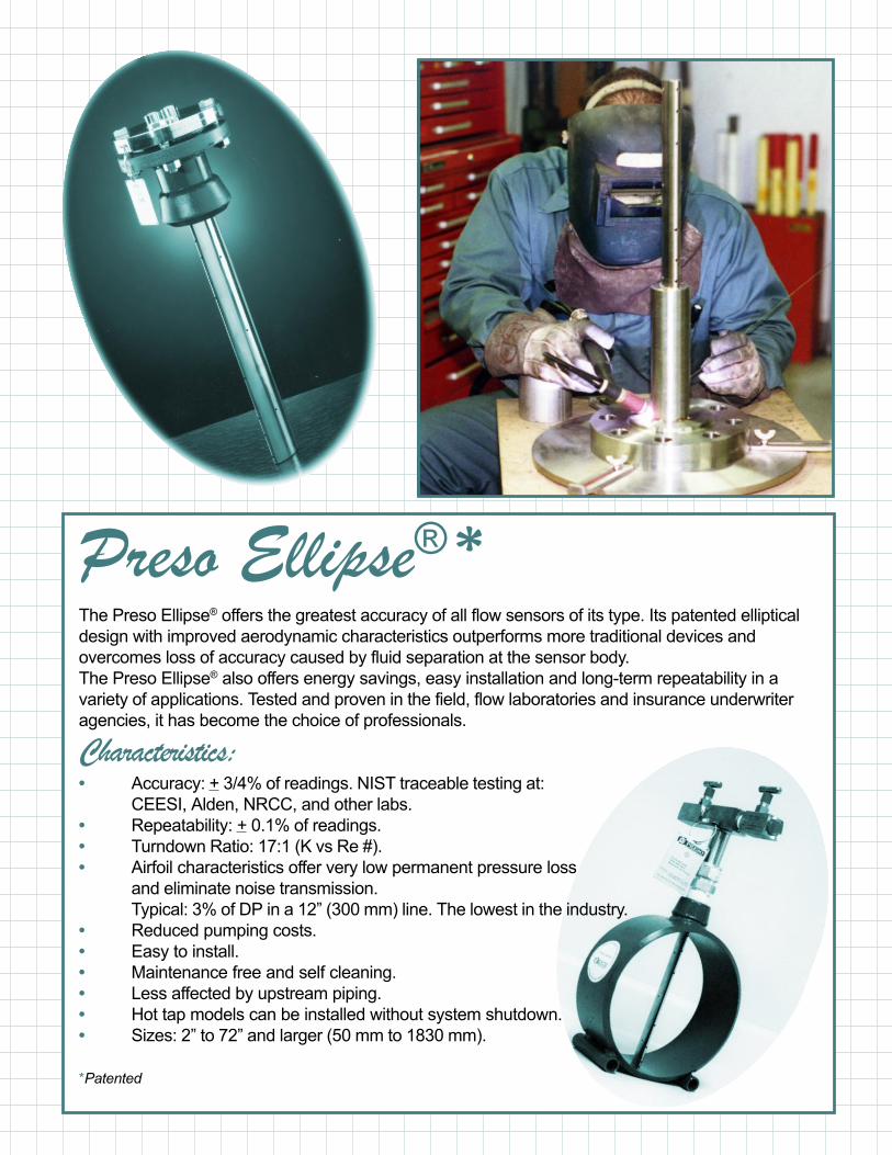
Preso Ellipse® *The Preso Ellipse® offers the greatest accuracy of all flow sensors of its type. Its patented elliptical
design with improved aerodynamic characteristics outperforms more traditional devices and
overcomes loss of accuracy caused by fluid separation at the sensor body.
The Preso Ellipse® also offers energy savings, easy installation and long-term repeatability in a
variety of applications. Tested and proven in the field, flow laboratories and insurance underwriter
agencies, it has become the choice of professionals.
Characteristics:• Accuracy: + 3/4% of readings. NIST traceable testing at:
CEESI, Alden, NRCC, and other labs.
• Repeatability: + 0.1% of readings.
• Turndown Ratio: 17:1 (K vs Re #).
• Airfoil characteristics offer very low permanent pressure loss
and eliminate noise transmission.
Typical: 3% of DP in a 12” (300 mm) line. The lowest in the industry.
• Reduced pumping costs.
• Easy to install.
• Maintenance free and self cleaning.
• Less affected by upstream piping.
• Hot tap models can be installed without system shutdown.
• Sizes: 2” to 72” and larger (50 mm to 1830 mm).
*Patented

Designed to Work BetterThe Preso Ellipse® flow meter is
designed with a series of ports
facing the upstream velocity pres-
sures and flow sensing ports stra-
tegically located ahead of the trail-
ing edge flow separation. As a re-
sult of this innovative design the
Ellipse® is capable of greater ac-
curacy than a conventional sen-
sor in measuring the actual DP
signal. With the Ellipse®, your
measurement is absolutely pre-
cise and proportional to the actual
flow rate.
Conventional
Flow Sensor
Preso Ellipse®
Flow Sensor
Proven SuperiorExtensive tests performed in rec-
ognized laboratories such as Alden
Research, CEESI, NRC, etc., have
demonstrated that the Preso El-
lipse® exhibits accuracies of +3/4%.
The Ellipse® also achieved an im-
pressive turndown ratio of 17:1.
These flow meters are even FM ap-
proved for use as fire pump flow
metering systems.
Incomparable AdvantagesWhen you look carefully at
Preso quality and performance
you can clearly see where your
advantage lies with the Ellipse®.
Ellipse® Outperforms Them AllCompare and see for yourself!
Round Shape
• Low (static) pressure signal
affected by separation.
• Turndown ratio of 4:1;
vacuum effects.
• Variable intensity vortices
generated behind (down
stream), leading the probe to
create signal amplifications,
vibrations and acoustic
problems.
• Accuracy of + 1.5% to 3%.
• High Drag coefficient inducing
high pressure loss.
Square Shape
• High vortices area resulting
from Large bluff body
obstructing the flow stream.
• Turndown ratio of 10:1;
vacuum effects.
• Highest drag coefficient of
exiting pitot type probes (i. e.
highest pressure loss).
• Claimed accuracy of + 1%.
• Vibration and acoustic
problems.
Ellipse® Shape
• Flow boundary layers
attached to the probe’s
surface, no separation
effects on the low (static)
pressure.
• Turndown ratio of 17:1; no
vacuum effects.
• Very high repeatability.
• Accuracy of + 3/4%.
• Lowest drag coefficient
(lowest pressure loss in the
industry).
Typical Cross Section. A : 1/2”
: 7/8”
: 1-1/4”
: 2-1/4”
Unstable
Vorticies
Stable
Attached
Flow

Very High Accuracywith the Ellipse®
The Preso Ellipse® offers NIST traceable accuracy
for each application of compensated mass flow
measurements and rate flow measurements.
The wide 17:1 turndown range offers a linearized
curve programmed into the multivariable transmitter
or the Preso MFC computer.
Characteristics:• Accuracy + 0.75% or better.
• NIST traceable calibration.
• Direct transmitter mount withmultivariable technology.
• True static pressuremeasurement.
• Single point pipe entry for:DP, temperature and staticpressure.
• No dampening softwarerequired.

Setup No.1: Ellipse® - SMVDirect mass flow metering with pressure and
temperature compensation. All features from one
sensor with one 4-20 mA output wired to your DCS.
A true insertion mass flowmeter which combines
the Ellipse® with the smart Multivariable Transmitter
Technology:
• Only the Ellipse® will provide true static pressure
measurement rather than a calculated value.
• Only the Ellipse® will provide the lowest perma-
nent pressure loss due to its aerodynamic profile,
• Only SMV uses one sensor technology to accu-
rately configure the 3 inputs.
Setup No.2: Ellipse® - STDFlow rate metering with 17 point linerization with one
4-20 mA output from the one sensor wired directly to
your DCS.
The Ellipse® with an uncalibrated accuracy of +0.75%
over a turndown (K vs. Re #) can improve accuracy
by calibration of the Ellipse-STD assembly in a NIST
traceable flowlaboratory. the 17 point linearization is
programmed into the transmitter to provide +0.5%
accuracy of reading
• Only the Ellipse® offers +0.75% uncalibrated
accuracy
• Only the Ellipse® offers a 17:1 turndown (K vs. Re #).
• Only the Ellipse® eliminates noise and dampening software.
Setup No.3: Ellipse® - P/TDirect mass flow metering with pressure and
temperature compensation. All features from one
sensor with one 4-20 mA output wired to your DCS.
A true insertion mass flowmeter which combines the
Ellipse® with the smart Transmitter Technology:
• Only the Ellipse® offers +0.75% uncalibrated
accuracy
• Only the Ellipse® offers a 17:1 turndown
(K vs. Re #).
• Only the Ellipse® will provide true static pressure
from either the static port or a dedicated pressure
port.

Preso... The Sensible
AR - Regular (2” to 72”)General purpose sensor used on air,gas and liquid.Pressure: 800 PSI (5,516 kPa) max.Temperature: 800 0F (427 0C) max.Standard Components:• T-Type head, 316-SS 1/4” or 1/2”
FNPT connection• CS compression f itting with SS
ferrule• CS 3000 lb. weld f itting - ASTM
A105• 316-SS ID tag with wire• 316-SS “Ellipse®” Sensor• Instrument valves (2 per sensor) -
1/4” or 1/2”, CSOptions:• Double support, CS or 316-SS• Weld f itting - 316-SS 150 lbs. or
3000 lbs.• Mounting saddle for PVC or FRP
pipes, CS or 316-SS• Temperature port with RTD output• Static pressure port with SS plug
AS - Steam (2” to 72”)Used on steam applicationPressure: 600 PSI (4,100 kPa) max.Temperature: 480 0F (250 0C) max.Standard Components:• T-Type head, 316-SS 1/2” FNPT
connection• CS Compression f itting with SS
ferrule• CS - OS & Y gate valves
(1/2” NPT)• CS 3000 lb. weld f itting, cross tees
and plugs - ASTM A105• 316-SS “Ellipse®” Sensor• 316-SS ID tag with wireOptions:• Double support, CS or 316-SS• Compression f itting - 316-SS
150 lbs. or 3000 lbs.• Temperature port with RTD output• Static pressure port with SS plug• 1/2” gate valves, OS & Y, 316-SS
Note: Specify pipe
AF - Flanged (2” to 120”)Flanged model used on air, gas andliquid.Pressure and temperature dependon flange ratings, ANSI B16.5 standards.Standard Components:• T-Type head, 316-SS 1/4” or 1/2”
FNPT connection• 150 lbs. 316-SS sensor flange• CS gasket with SS spiral wound
ring• CS mounting flange, 150 lbs.
ASTM A105 with nuts and bolts• CS 3000 lb. weld f itting - ASTM
A105• 316-SS “Ellipse®” Sensor• Instrument valves (2 per sensor) -
1/2”, CS• 316-SS ID tag with wireOptions:• Double support, CS or 316-SS• Spiral wound gasket, 316-SS• 300 lbs., 600 lbs., and higher
flange rating, CS or 316-SS ANSIB16.5
• Temperature port with RTD output• Static pressure port with SS plug

AHR - Wet Tap
(Low Pressure) (2” to 36”)Wet-tap model used on liquid, air, and
gas. For liquids without system shut-
down. Ratings:
i) Insertion/Removal:
Pressure: 75 PSI (500 kPa) max.
Temperature: 1200F (500C) max.
ii) Operating
Pressure: 150 PSI (1000 kPa) max.
Temperature: 2000F (1000C) max.
Standard Components:• T-Type head, 316-SS 1/4” or 1/2”
FNPT connection
• CS compression Fitting with SS ferule
• 316-SS isolation ball valve, NPT
• CS reducer coupling
• CS 3000 lb. weld fitting - ASTM A105
• CS nipples, schedule 40
• 316-SS “Ellipse®” Sensor
• 316-SS ID tag with wire
• Instrument valves (2 per sensor) -
1/4” or 1/2”, CS
Options:• Double support, CS or 316-SS
(only with system shutdown)
• Compression Fitting - All 316-SS
• Weld fitting - 316-SS 150 lbs. or 3000
lbs.
• 316-SS cage nipple
AHL - Hot Tap
(High Pressure) (2” to 72”)Hot-tap model used on liquid, air, and
gas without system shutdown
Pressure: 800 PSI (5,500 kPa) max.
Temperature: 8000F (4250C) max.
Standard Components:• T-Type head, 316-SS 1/4” or 1/2”
FNPT connection
• CS packing chamber with molythane
or graphite packing gland
• 316-SS sensor flange, 150 lbs.
• CS packing chamber flange, 150 lbs.
with SS cap
• 316-SS isolation ball valve, NPT
• CS threaded nuts and bolts
• CS nipples, schedule 40
• CS 3000 lb. weld fitting - ASTM A105
• 316-SS “Ellipse®” Sensor
• 316-SS ID tag with wire
• Instrument valves (2 per sensor) -
1/4” or 1/2”, CS
Options:• Double support, CS or 316-SS
(only with system shutdown)
• Weld fitting - 316-SS 150 lbs. or 3000
lbs.
• 316-SS rods, bolts and nuts
• 316-SS packing chamber and flange
AHL - GD
- Hot Tap
(High Pressure) (2” to 72”)Hot-tap model used on liquid, air, and gas
without system shutdown
Pressure: 800 PSI (5,500 kPa) max.
Temperature: 8000F (4250C) max.
Standard Components:• T-Type head, 316-SS 1/4” or 1/2”
FNPT connection
• CS packing chamber with molythane
or graphite packing gland
• 316-SS sensor flange, 150 lbs.
• CS packing chamber flange, 150 lbs.
with SS cap
• 316-SS isolation ball valve, NPT
• CS threaded nuts and bolts
• CS nipples, schedule 40
• CS 3000 lb. weld fitting - ASTM A105
• 316-SS “Ellipse®” Sensor
• 316-SS ID tag with wire
• Instrument valves (2 per sensor) -
1/4” or 1/2”, CS
Options:• Double support, CS or 316-SS
(only with system shutdown)
• Weld fitting - 316-SS 150 lbs. or 3000
lbs.
• 316-SS rods, bolts and nuts
• 316-SS gear drive enclosure with
handle
• 316-SS packing chamber and flange
Choice in Flow Sensors

Air Flow Measuring StationThis series utilizes the
unique “Ellipse®” design
and is available in multi-point
averaging insertion sensors
and complete duct section flow
stations with averaging arrays.
The stations are available with
or without flow straighteners
and offer an ASHRAE design
pitot-static array.
• AYR: Insertion style sensor
available for circular,
rectangular and oval ducts.
• SYR-RYR: ASHRAE
averaging array for square or
circular ducts.
• SYP-RYP: ASHRAE
averaging array for square or
circular ducts with built-in
flow straighteners.
Engineering DataDifferential Pressure CalculationBasic Flow Equation
For square or rectangular ducts use equiva-lent diameter formula:
D (equivalent) =
Design Features• The PRESO “ELLIPSE®” offers the greatest
accuracy of all flow sensors of its type.
• Its patented elliptical design with improvedaerodynamic characteristics outperforms moretraditional devices, and overcomes loss of accuracycaused by fluid separation at the sensor body.
• Energy savings, easy installation and long-termrepeatability makes it the first choice ofprofessionals.
For complete glossary of terms, K-Factors andEngineering Details, consult your local representativeor the factory.
C = 128.8 x K x D2 x Fa
0FSCFM = ACFM x xPF.(psia) 520
14.73 T + 460
( )0.54 x W x Hπ
SCFM SGS(T + 460) C1 PF.(psia)
( )2 0F∆P = X

Preso FlowCalc ProgramPreso Flow Calculation Program is made for Windows. It is a unique tool for sizing
Preso products and choosing the right flow element. It allows the user to enter
data pertinent to a customer’s unique application, figure the differential pressure
based on flow conditions and choose the proper flow meter.
The program is a menu driven, pull down type. It covers all of Preso’s primary
elements including:
• Multi-Port Self Averaging Pitot Tubes (Annular “Ellipse®” and round sensors)
• Venturis (Low Loss, Classical and Modified)
• Coin, Segmented-Wedge Meters (NPT, flanged or chemical seals)
• Air Flow Products (Air sensors, square, round or rectangular stations)
FlowCalcs Program
Program Features• Sizes Flow Element bores for Venturis
(Low Loss, Classical or Modified).
• Performs Liquid, Steam and Gas
(Volume or Mass) calculations.
• Calculations are done in English or Metric
(SI) units.
• Calculations are done to Miller/Spinks,
ASME, AGA and ISO Standards
• It calculates the maximum allowable DP,
resonance and pressure losses for Multiport
Self Averaging Pitot Tubes “Ellipse®” or Round.
• Flow calculation reports are generated
for each tag number with
messages, warnings and
recommendations.
• It has a unique feature in
calculating Reynolds Numbers
and DP at minimum, normal and
maximum flow conditions.
While Preso have invested considerable time and money to create a high
quality product, the user must assume the risk of using this product. In
no event will Preso be liable for direct, indirect, special, incidental or
consequential damages arising out of the use of or inability to use this
software or documentation.

Water TestCalibration of an 8” single support probe “Elliptical” shapeModel AR-800, 8” sch. 40 pipe D = 7.9810”Alden Research Laboratory Inc., April 1987 APL No. 35-87/C549
Reynolds Number (based on pipe diameter) x 100,000Flow Coefficient (K) + 3/4 %
Air TestCalibration of a 3” and a 10” single support probe “Elliptical“ shape3” sch. 40 pipe, D = 3.068” and 10” sch. 40 pipe D = 10.149”Colorado Engineering Experiment Station Inc.3” test date: May 16, 1988; serial no. 88PRI110” test date: Aug. 5, 1987; serial no. 87PRI1
Reynolds Number Rd x 100,000Flow Coefficient + 3/4 % 10” sch. 40 + 3/4 % 3” sch. 40
Engineering DataDifferential Pressure CalculationThe basic flow equations for the self-averaging pitot-tube or (Annular Flow-meter) are derived from the Bernoulli’s Theorem (Energy Balance), andthe Continuity Equation.The most common equations used by the industry, where different unitsare employed according to the flowing conditions of each type of fluid areas follows:
(i) Liquid
(ii) Gas / Air
(iii) Steam
Where∆P - Differential Pressure; Inches of water column at 600FGPM - US Gallons per MinuteSCFM - Standard Cubic Feet per Minute at 600F and 14.73 psiaACFM - Actual Cubic Feet per MinuteLbs/Hr - Pounds Mass per HourC1 - Flow ConstantK - Flow CoefficientDi - Inside Pipe Diameter, InchesFa - Thermal Expansion of the Pipe; 1 up to 1000F/1.001-1.005
(100-5000F)Tf - Flowing Temperature, 0FPf - Flowing Pressure, psiaSGf - Specific Gravity at Flowing ConditionsSGS - Specific Gravity at Standard Conditions (700F, 14.73 psia)ρf - Flowing Density, lbs/ft3
Resonance CalculationsResonance occurs when the natural frequency of the “Ellipse®” sensorcoincides with the natural frequency of the travelling fluid (StrouhalFrequency). Vibration checks should be done only on gas and steamapplications.Vibration ratio “R” should be less than 0.8 or greater than 1.2 i.e.0.8 < R < 1.2, R should be outside this region.
L: Critical Probe Lenght, InchesModel AR AF AS AHR AHL
Single Support ID+W+ 1.30 2.5 1.30 6 6Double Support ID+2W+ 1.35 2.8 1.35 ~ ~
C1 = 5.6660*K*Di2*Fa
C1 = 128.8*K*Di2*Fa
( )2∆P = * SGFGPM
C1
Note: SCFM = ACFM* *Pf
14.73520
Tf + 460
( )2∆P = ** SGF
SCFM SGS(Tf + 460) C1 Pf
R = VmaxVC
Vmax = 3.05577 * ACFM(ID)2
Vc = SL2
S = 16927 for (7/8)” probeS = 36608 for (1 1/4)” probeS = 119798 for (2 1/4)” probe
Vmax: Maximum fluid velocity, ft/secVc: Critical velocity, ft/sec
S = probe factorL = probe length, see tableW = pipe wall, inchesID = inside pipe diameter, inches
Lbs/HrC1
C1 = 359*K*Di2*Fa*√ρf ( )2∆P =
*
Flow Coefficient (K)Pipe Size K K K(Inches) Probe Size Probe Size Probe Sizesch. 40* 7/8” 1 1/4” 2 1/4”
2 0.6295 ~ ~2 1/2 0.6304 ~ ~
3 0.6364 ~ ~3 1/2 0.6523 ~ ~
4 0.7180 ~ ~5 0.7288 ~ ~6 0.7377 ~ ~8 0.8088 0.7633 ~10 0.7829 0.7515 ~12 0.7446 0.7375 ~14 0.7333 0.7457 0.721216 0.7281 0.7144 0.713318 0.7201 0.7125 0.711520 0.7196 0.7105 0.710024 0.7187 0.7050 0.665526 0.7169 0.7042 0.688830 0.7155 0.7025 0.701536 0.7111 0.7017 0.698542 0.7100 0.6995 0.6979
Note - for different pipe schedule - consult factory.*14” & up - sch. STD.

Typical SpecificationsFurnish and install as shown on the drawings a flow elementof the multi-ported, self averaging differential pressure typeELLIPSE® as manufactured by Preso Meters Corporation.The flow element shall be of maximum two (2) piececonstruction, of an elliptical shape with two (2) 100%independent flow sensing chambers to prevent signaldegradation and mixing or that require dampening hardwareor software. The impact velocity sensing holes shall belocated along the leading edge and the true static sensingholes shall be on the exterior probe side. The quantity andposition shall be as determined by the manufacturer. Theprobe must not generate any vortices or vacuum effects thatimpinge on the static pressure measurement sensing areaand have a drag coefficient of 0.32 or less. Each flow sensorshall be complete with instrument shut-off valves withprovisions to accept a transmitter or direct indicating metersupplied by the same manufacturer as the primary element.An identification tag shall be supplied with specific flow stationmeasurement information as required.
Installation Requirements1. Orientation: The “Ellipse®” flow sensor can be installed vertically
or horizontally. The probe should be mounted in the pipe 900
relative to the flow direction.2. Straight pipe requirement: Accuracy is affected by the piping
configurations due to the disturbances of the flow profile. A fullydeveloped symmetrical flow is kept with the minimum upstreamand downstream recommended lengths.
Distances are Expressed inNominal Pipe Diameters
Pressure LossPreso “Ellipse®” sensor offers the lowest pressureloss of all types and shapes of its kind.
• Very low permanent pressure lossThe low drag coefficient of the Preso “Ellipse®”flow sensor allows the measurement to be takenwith high accuracy, and hardly any pressure loss.
Sensor Shape* CD Drag Coefficient
Circular (Round) 1.2Square 2.0Diamond 1.6Semitubular 2.3“Elliptical” 0.32
Maximum Allowable DP(Inches of Water Column)
Single Support Double SupportPipe Size Probe Size ProbeSize(Inches) 7/8” 1 1/4” 2 1/4” 7/8” 1 1/4” 2 1/4”
2 880 ~ ~ 2380 ~ ~2 1/2 525 ~ ~ 1568 ~ ~
3 396 ~ ~ 1283 ~ ~3 1/2 283 ~ ~ 1117 ~ ~
4 197 ~ ~ 980 ~ ~5 153 ~ ~ 757 ~ ~6 126 ~ ~ 689 ~ ~8 114 360 ~ 512 ~ ~
10 100 240 779 315 960 ~12 87 175 660 250 700 ~14 53 147 610 195 585 ~16 ~ 113 495 ~ 450 ~18 ~ 90 410 ~ 360 ~20 ~ 74 346 ~ 295 ~24 ~ 68 315 ~ 270 95226 ~ 50 218 ~ 215 87830 ~ 34 187 ~ 155 78032 ~ ~ 136 ~ ~ 55036 ~ ~ 105 ~ ~ 41042 ~ ~ 85 ~ ~ 350

Rev. Ellipse 4-2008
Preso“COIN” MeterThe “COIN” is a segmented wedge primary �ow elementspeci�cally designed for the most di�cult �owapplications.It e�ectively measures any �uid, even those with verylow Reynolds numbers.
Characteristics:• Accuracy ±3% uncalibrated to ±0.5% calibrated• Bidirectional• Sizes - 1/2” to 48” and larger• Butt weld or �anged ends• NPT, �anged or chem tee instrument connections• Available in many materials• ISO 9001 certi�ed design and fabrication
• • • • •• •• • •
•• •• • •• ••
• • • • •• •• • •
•• •• • •• ••
• • • • •••• • •
•••• • ••••
Other Preso Products to Meet Your Needs...
Preso manufactures a complete line of annular and Venturi style �ow meters to measure liquid,gas and steam �ow applications.A full line of gages and �ow computers to read in direct engineering units are also available.
8635 Washington Avenue • Racine, WI 53406Tel: 262-639-6770 • Fax: 262-639-2267
Toll Free: 800-632-7337www.preso.com • [email protected]