derex ac140 140 ton truck crane
DESCRIPTION
When fully retracted, the main boom is 12.5 m long, when fully extended it is 60 m. All telescopic sections must always be pin-ned at these and all other working lengths. This means that each boom section is locked to the next largest boom section by a spring-loaded pin or bolt (3) on the left-hand and right-hand sideTRANSCRIPT
FAILURE MODED EFFECT ANALYSIS
NIS TECHNOLOGY SERVICE GROUP
Date April 16, 2008
Developed By: Crane Safety Associates of America, Inc.
Phillip S. Ezzell

TEREX I DEMAG
AC 140
1/1
INTRODUCTION
This analysis is based on the subject equipment being properly assembled and in the correct configuration to perform the work, set up according to manufacturer's specification including level state, proper cribbing, lubrication, fluids levels, and adjustments.
Since the specification for this analysis did not describe the crane configuration, the weight, radius, or height of the lift, several options will be analyzed.
Some illustrations will not be an exact match; however, they will contain the same components as described by the manufacturer.

HOOK BLOCK

INDEX
Pages
1 ................................... Item Description
2. . . . . . . . . . . . . . . . . . . . . . . . . . . . . . . . . .. Pictorial Diagram
3 . . . . . . . . . . . . . . . . . . . . . . . . . . . . . . . . . .. Itemization
Component Identification
1 ................................ , Bearing and Spacers
2 ................................. Sheave
3 ................................. Trunnion
4 ................................. Becket Connection Point and Dead End Pressed End Socket
5 .................................. Cheek Plate
6 .................................. Through Shaft
7 .................................. Shank Nut
8 .................................. Bearing

SYSTEM DESCRIPTION
HOOK BLOCK
Hook blocks are used to increase hoisting efficiency on crane and hoisting systems by means of increasing the number of running wire ropes thought encase sheaves. Attached to the encasement or block is a single or multiple barb hooks. The hook provides a means to attach loads usually using suspension gear such as slings.
This crane comes with a variety of hook options that can be used based on the weight of the loads to be hoisted and the hoisting speeds desired. The description given for the analysis and inspection will apply to all hook block options. The only differences being the number of sheave and possibly a double hook verse a single hook.
The hook block will have a wedge socket connect located either on top or to one side of the block for the purpose of securing or dead ending the wire on the block when odd number of parts is required.
1
MANF ACTURER:
TERREX - DEMAG
HOOK BLOOK OPTIONS:
TYPE 200-9/21-D 9 SHEAVES DOUBLE HOOK WEIGHT 1750 KG 1 OR 2 HD ATTACHMENTS (MAX 16 PARTS)
TYPE 100-7/21-D 7-HEAVES, MAX 13 FALLS, DOUBLE HOOK WEIGHT 1000 KG
TYPE 80-5/21-E 5-SHEA VES, MAX 11, SINGLE HOOK, WEIGHT 945 KG
TYPE 80-3/21-D 5- SHEA YES, MAX 11 FALLS, DOUBLE HOOK, WEIGHT 945 KG
TYPE 63-3/21-E 3-SHEAYES, MAX 7 FALLS, SINGLE HOOK, WEIGHT 700 KG
TYPE 63-3/21-D 3-SHEA VE, MAX 7 FALLS, DOUBLE HOOKS, WEIGHT 700 KG
TYPE 32-1I21-E 1- SHEAVE, MAX 3 FALLS. SINGLE HOOK, WEIGHT 550 KG
TYPE 32-1/21-D 1 SHEAVE, MAX 3FALLS, DOUBLE HOOK, WEIGHT 550 KG
TYPE 8-0/21-E HOOK SUPENSION GEAR, WEIGHT 250 KG
2
Component Identification
1 ................................. Bearing Spacers and Sheaves
2 ................................. Trunnion
3&4 ............................. Becket Connection Point and Dead End and Pressed End Socket
5 .................................. Through Shaft
6 .................................. Shank Nut
7 .................................. Hook
8 ................................. Hook Safety Latch
9 ................................. Wedged Socket (Becket)
10 ................................. Press End Socket
3

U)
""'" I I I
-2-
, , " ,
co "ll:
I I I
, , , I ,
-, ~ ,
A
o

17.2.2 Hook blocks (Z 50 696)
17.2.2.1 Definition
Reeving 17
In DIN 15002 the hook block is defined as the "multiple line suspension of carrying equipment with a hook".
A single-line suspension would be referred to as a hook suspension gear. As this differentiation is not relevant for the following general contexts, only the description "hook block" is used.
17.2.2.2 Markings
The following details must be permanently and legibly marked on hook blocks:
Warning marking
- Manufacturer or supplier - Year of construction
- Type, if type designation applies
- Factory or serial number - Permitted load
- Rope diameter - Drive group
- Dead weight.
25/35
17
E1
13
Z 52 200 K
Z 53 402
18/35 c

Reeving 17
Rope end connection "without press fitting"
(Z 41 377, Z 200 177, Z 41 379, similar depiction)
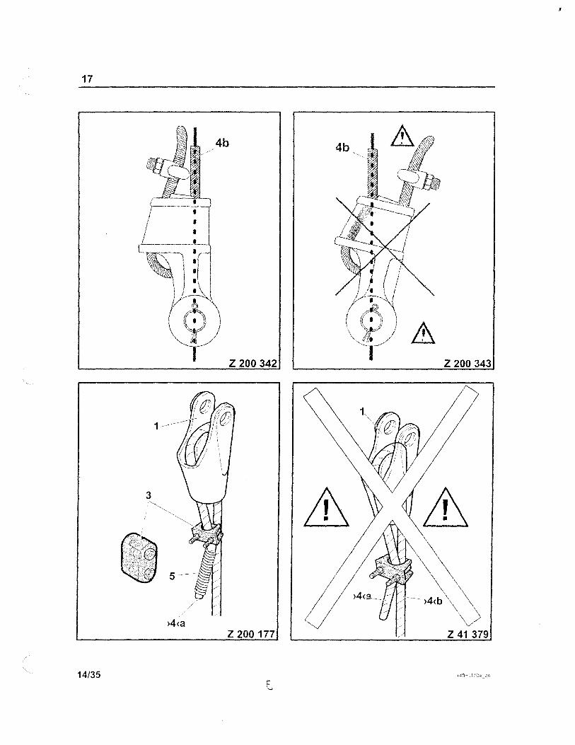
The illustrations ofthe rope socket (1) and the cable clip (3) are principle drawings and do not correspond exactly with the components supplied by the crane manufacturer. Use only original parts supplied by the crane manufacturer.
In order to fit the rope socket (1), first the free rope end is pulled through the conical rope pocket, laid in a loop and then pulled out of the rope pocket again. The rope key (2) is laid into the rope loop and the hoist rope"is pulled through the rope socket (1), so that the free end juts out by approx. 8 times the width of the rope diameter. The free end must be secured against pulling using a cable clip (3) of the correct size.
Danger of the load and I or the hook block falling down!
13/35
D
I
17
4b
Z 200 342 Z 200 343
1
3
Z 200177 Z 41 379
14/35

Reeving 17
Rope end connection "with press fitting"
(Z 41 375, Z 41 383, Z 41 384, similar depiction)
The rope end connector of the rope "hoist 1" comprises the forlowing components (Z 41 375):
- th e rope socket (1)
- the flap (2) with mushroom grip (4)
- the rope sleeve (3)
The rope sleeve (3) is a component of the hoist rope and is firmly fitted to it.
- To secure the rope end, it is inserted in the rope socket (1) with the help of the fitted rope sleeve (3) and secured with flap (2).
- Before fitting the rope sleeve (3), fold up flap (2) with the help of mushroom grip (4) (Z 41 383).
- After fitting the rope sleeve (3), fold flap (2) into the "lock" position and insert the locking pin using the mushroom grip (4) (Z 41 384).
Before reeving the rope "hoist 1" on the main boom, on the fly jib and on the main boom extension, all rope protection arrangements such as roUers or bolts on the reeved deflection and rope idlers must be removed or opened. If this is not done, the hoist rope with the attached rope sleeve cannot be drawn through, when reeving the hoist rope using the auxiliary reeving winch there is a risk of damage for the winch, the sheaves and the hoist and auxiliary reeving rope.
11/35
I

I.:.
17
1
Z 41 375
(1 2 4
3 3
1 Z 41 383 Z 41 384
10/35

17
1
Z 53 401
\-\ 2/35
I
17
Z 55 368 Z 55 369
8/35
INSPECTION AND ANALYSIS (SINGLE POINT ANALYSIS)
BEARINGS SPACERS AND SHEEVES
Hoist Block Sheaves operate within the block and boom point with the assistance of spacers. Spacers separate the sheaves in order to provide a necessary even load on the boom head. The hook block maintained a like distance to allow for eccentric reeving as to not cause the boom head to twist which in the extreme could cause the boom to fail with loss of load.
Bearings allow sheaves to rotate with a minimum of friction or lateral movement or wobble. Defective sheave bearings may cause the sheaves to freeze causing eventual failure of the wire rope causing loss of load.
A visual inspection should be conducted by the crane operator, lift coordinator, or designated N.S.I. staff during the pre-lift meeting on the job site.
The inspection should consist of insuring that all sheaves are operating properly and no damage or excessive wear is present.
1
INSPECTION AND ANALYSIS (Single Point Failures)
ITEM # 2 - TRUNNION
Trunnion failure would cause the upper portion of the hook block (containing the sheaves and through shaft) to separate from the lower portion of the hook block.
Complete failure of the trunnion portion of the hook block will result in total loss of load.
The trunnion should undergo a visual inspection by the crane operator, lift coordinator, or other designated personnel at the lift site, this portion of the block is difficult to effectively perform a visual inspection of the wear areas. Look for signs of looseness, freezing or sticking and wear. It is recommended to have the block disassembled for a NDT prior to the lift if it has not been done within the past 12 months. This item should be deemed passive before the lift is made.
2

sockets, proper length preparation of dead end on wedge sockets, on pressed end sockets check socket connector on rope for any signs of slippage, check the mushroom grip, flap, and sleeve for proper operation or damage.
This item will be deemed passive before proceeding with the lift. Inspection does not require disassembly.
4
INSPECTION AND ANAL YSIS (SINGLE POINT F AlLURES)
ITEM # 5 - THROUGH SHAFT
The sheaves are held in place by a shaft that passes through the sheaves and attaches to the inner plates of the block housing. If the through shaft breaks the sheaves and the wire rope may fail or detach causing loss of load.
The hook block should be disassembled and inspected by the crane operator or mechanic in the absence of a recent NDT report or certification. If the inspection is to be visual, after the inspection by the crane operator and the authorize field representative and the lift coordinator, if deemed passive the block should be reassembled and documentation of the inspection provided to N.S.l.
5
INSPECTION AND ANALYSIS (SINGLE POINT FAILURES)
ITEM # 7 - SHANK NUT
The Shank Nut holds the hook in the block assembly. Should the Shank Nut completely fail, the hook would separate from the hook block, resulting in loss of load.
A visual inspection of the Shank Nut will be performed by the crane operator, lift coordinator, and designated persons on the N.S.I. staff during the pre-lift meeting at the job site. Inspection should insure there are no distortion of the nut, cracks, and proper tightness to not prevent rotation of the hook. This item shall be deemed passive before the lift is made.
6

INSPECTION AND ANALYSIS (SINGLE POINT FAILURE)
HOOK
The hook is the load bearing point of the hook block. Structural failure of the hook will result in loss of load.
The hook should undergo a visual inspection during the pre-lift meeting by the crane operator, lift coordinator and designated persons on the N.S.I. staff. The inspection can be perfonned on site and does not require disassembly.
The hook inspection should consist of looking for hairline cracks, spreading of the hook by more than 15% of the original throat opening, loss of 10% or more of the original hook material, twisting, evidence of heat damage such as welding.
7

WIRE ROPE
INDEX
Pages
1 ................................... Item Description
2 ................................... Pictorial
3 .................................... Wire Rope Options
4 & 5 ............................. Failure Analysis & Inspection

ITEM DISCRIPTION
WIRE ROPE
The load line on this crane is designed specifically to be used as running wire rope. This means the rope is designed to travel through and around sheaves located within the hook block and the boom-point head to the hoist drums located on the superstructure.
The wire rope is designed to perform to the necessary bending, wear, and fatigue factors common in hoisting operations. It is made up of three main components, wires, strands, and a core rope usually IWRC. In order to meet U.S. standards the ropes must only be loaded to a fraction of the breaking strength or ultimate strength. Six and eight strand ropes shall work with a factor of safety of no less than 3: 1. Rotation resistant rope shall work with no less than a fact or of safety of 5: 1.
1
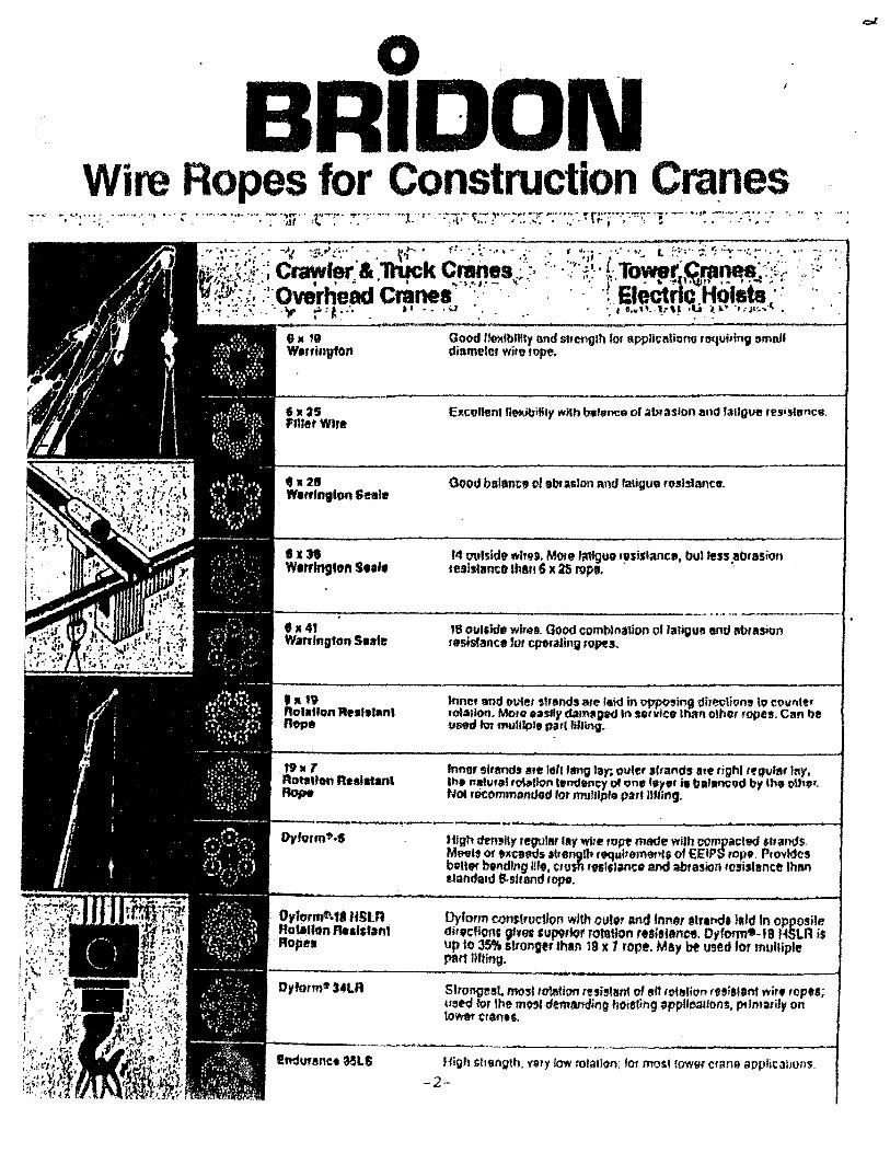
o . BRIDON
Wire Ropes for Construction Cra.nes
fh '9 W."ington
,.28 W."lnglon Seale
8X38 W,,.,lngton S.tl.
Good 1Ie?<lblHty Illld slnmglh fOf appli~l\lion' re-qlljrln9 &mall diameter wi'e ,ope.
Excelenl f~ibi!ily with b,dance) of abtaslon alld fallgue re,i,'ance.
0000 balanc, of e'" aslon "I'!d laligu9 rosistance.
14 ~'sidt w,,~ •. Mote 'allguo "s;slance, bul fess ,abraSion reSI,Utm::ft Ihan 6 X as 1'01'1, .
----."...--------------------.. -.. -- -------1 'x41 Wa,dngton Seale
'Jt 19 Rolatlon Fle.l.tanl Rope
O,form&.t'ItSLR hotallon ..... 'fan1 Ropes
I!ndUf8net MlS
18 oul,ldo wlr ••. Good combina1ion 01 fatigue and abrasion sesistance 'or operallow ropes.
Inne, and outer ,bands are 'aid in 9ppo,jng dj,~tione \0 coville, ,ot~!IOn. 11.10'0 o;tllly dQm2l01d In "rvlce Ulan other topes. Can be U69d lor mull"". pa,t "'ling.
'nne, ,I,ands llle '0'1 fang lay; olleer strands ale righl '('guill' lay, In. n~Uf.1 'o\~lon '.mlen!:), of 011' ."", i. ballflC9d by th9 o\h",. Not rocomm9ndod f01 mulllp'o par' IIfling.
Dyform con$truclfOfl wIth ovl" and fnno, e'r.tid. la'd In opposire di"tfioIlC 9'ves cUPf,tor rotation , •• iSlance. Orform'l-1B HSLR is up to 35'Pt stronger than 19 x 7 rope. May be U!ed 'or multiple paM JiJling.
Sirongest. mosl rolation "n;~'!Sm of Itlt 'olarion ,..,iSUlnf wir. lOP"; lIst<j for Ihe most demanding hOle(ifl9 ~pp"oaIlon'. prltmui'v on to'hOf ~ran.'.
mgh shength. very low rotalion; for moS! lower crane appliC3l1oflS.
-2-
"
-
Ol.m, I". 1\ K, %
ti.
" ~
}\ , lYe 1%
-3-
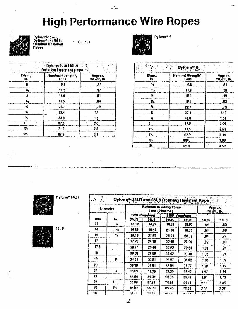
High Performance Wire Ropes Dtfotmi!'·1e .Jm" Dy'o,m~.l1 nOln nollllgn A",te1.nl Rt)PU
* S.P.F
----~-.
.' . Dv'ormfJ.'8 USU1 . " ':;' . . ,
R'1'IIIIori'''rits'.nt nope"';' "
... _.- ._" Nomln" Slftngtb·, A,n~Jt.
Tom, WU I., •• , . ~ 8.3 .21
tI:! :Jl 14.0 .In
".5 • 64
'''.7 .79 32 •• U
43,' '.$ ~1." 2.0 7Ui 2.' --81.0 3.1
.. ; I . .•
t:
.
. '; r! :~. ~ Dr'om1~.1 : .. : ': ~~ . ,
t •. " ... , ..... : ," "' .. ,. ,!t",.H· ". O'-m., Hennlm .. "renuth-,
ht. - ~ ..... , ... , T,vrt. --n 0.8
1',. fU K IG.3
~ . 1\1.3
" ~2.7 -~ 32.4
,* "".8 1 51.5 . . 1K 11.5
1Y. ~ '* 'ottO US '2$.0
-------.---. -..... .
I\~ro". WI. ",111. , .. ,
.31
.:19 ~
.-19
.GJ -..--.... ------
.70
'-'3
~J~ 2.00 t.G1 . 3.14
3.80 ..... . 4.50
• T
~::: .' , ., . ..' '... ,- .. '. " ',' .. ,~ .. ) ,.: ,.' .. OY'o,n'l'''~~.~~~\.~'-''' .. S .. ,,~~~~ ~~~ta;~~I.,,\~~? '!./
DIM,.," Minimum ..... Ing Fome Arp,oll. TOM_~"'.' WI.!,.. • .,.
1110 "'m""..". ItHnlmm'g ,
mm In. Mlll hU ~41.R 'SLI --HJ!...... 3SlS 13 ~ 1$'" 14.27 11.2' 1$.'" .51 ,00
38LS '4 ~. ",88 tfU2 2t.13 18.55 .''1 ,58 . .. ----16 ~ 15. tlJ 21.69 28.21 24.39 .01 .11 II 21.20 l4.29 30.46 ---21.20 .02 ,00 11.5
. 28.11 20 ... ' 32.12 29CH tOt .ttl --- . .....
'9 30,90 27,09 34.81 30.-10 1.05 .97 .. . ,. » 3Un 30.9. 38.61 ~.62 UI'S UJ!J - .. ro 31.39 ~3.f" 42.94 31.17 t.20 1.111 ~
~ . ~\ 48.m 4t.33 52.38 4r.."2 ,-Sf 9,4"
t4 ~5.tw 49.:M 623B _.-
55.'" 1.01 1.13 -~ ~~ --26 t ()fW 57," 74.1. SU4 2.'6 20!)
~e ---- ---m 1~.9U 66.99 8~,20 12.tH 2,53 ~3' . - ~--. - .. -111 nil H "I" All ., I "'I " 1 .... J . , , ,
2

TYJ>E: ONE OP TIlE POLL 0 WING
6 X 19 IlYRc Ps 3.5:1 6X 25 IWgCPS 35'1 8 X25 IWgC Ps 35:1 8 X 19 IWgc Ps 3.5:'1
DY-P
ORlvl-18-lISLR Ps 5: 1 SPECfPICA nONs:
DIAMETER UN-iovOWN
WEIGlIT fJNJ(NOWN LENGTJi ..
BREAKING ST'T~BNGTlI KNoWN
3
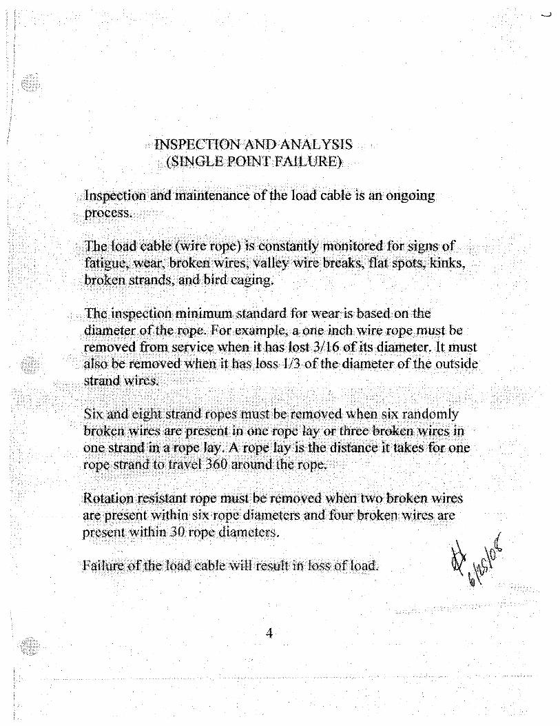
INSPECTI()NAND ANALYSIS (SINGLE POINT FAILURE)
Ingpectionand maintenance of the load cable is an ongoing prQ~~~S~
n~loadcable«wirerope)··is·c()nstandy·m6nitored for sigQs of f~~~gtte~.~~ar;'Prokenwires,<valleywite breaks,tlatspois, . kinks, b~gk~n··~tr~ds;~and'Pirdcaging~
tb~<.ins:p~.~tiQl1minimunlstandard for wear is 'Pasedon the qi~~t~rQftbe.rQPe~ FOl" eX aIl}pl¢,aone inch wire rope must be re~(>~ed fr()~s~ry:ice whenithas lost3/16ofitsdia,meter. It must also be removed when ithas loss 1/3 of the diall}etcr of the outside
~.~.~ •.•..• ~.~ .•• · .• ~i~.~ .•. · .••. §~r~tia •. ·ro~es .. ml:tst.··b~rem(Jv~d ... ~b¢l1. six .. randomly bf:Q~¢l1 ...• ~~e~ ...• ~~ •. ··p~es¢~t. in.o~~ .. ~ope.··l~{ .• or··~llre~ ..•• ~r~k.~n ..•. ~iJ;~sip ql1~~tf:~l1d<~i~i.~~~~lay .. .t\.···~~~~.·l~r.·.is .the distanc~ it·.takesfQrone r(}p~s ~g·tf:~v~l3QO.(.lr()qntitb¢. rope.
Rgt(.ltjgll resis\anttope must be removed when two broken ~if:es ar¢present within·· six· rope diametersand·fourbrokenwires< are pl"~sent withinJQ. rope diameters.
4

A visual inspection by operator, lift coordinator, and designated persons of the N.S.!. staff is paramount. The load cable will be deemed passive before the lift is made. No disassembly is necessary however the rope (load block) may need to be lowered to check the underlying wraps on the hoist drums.
5

BOOM LIFT GROUP
INDEX
Pages
1 ................................... Item Description
2 ................................... Specifications &Pictorial
3 &4 ............................... Failure Analysis & Inspection
ITEM DESCRIPTION
BOOM
The Hydraulic Boom component of a mobile hydraulic truck crane serves several purposes. The boom is cantilever type which consists of several telescoping boom sections. The sections are moved inward and outward in a designated sequence by means of hydraulic linear actuators (cylinders). The boom provides the means to support the load line and hook block over the load to be lifted. It also allows the tip height and working radius to be adjusted as desired.
1
MANUFACTURER: DEMAG
TYPE:
HYDRAULIC
TELESCOPIC
TWO WAYS
SPECIFICATION:
CAPACITY: 140 ton
12
8/73
2
4
3
2
4
3
3
3
Z 200 036

Telescoping 12
12 Telescoping
12.1 General (Z 54 716, Z 54717)
"Telescoping" means retracting or extending the main boom.
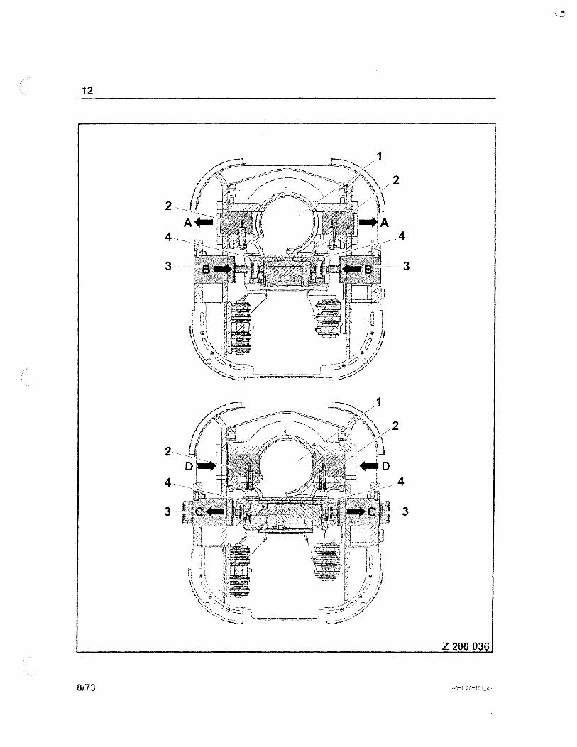
The main boom consists of a basic case and five telescopic sections. When fully retracted, the main boom is 12.5 m long, when fully extended it is 60 m. All telescopic sections must always be pinned at these and all other working lengths. This means that each boom section is locked to the next largest boom section by a spring-loaded pin or bolt (3) on the left-hand and right-hand side at the rear.
There are also load capacities in the unpinned condition. Refer to section 12.4.1 "Lifting Capacity at Intermediate Conditions", starting at page 63.
All five telescopic sections are retracted and extended using the following elements:
- - a telescoping cylinder (1), which is fastened to the back of the basic case.
- a safety and locking unit "LPU" (5) attached to the cylinder pipe. It is connected with the top of the piston rod of the telescoping cylinder via a pulling frame (6) and is therefore moved as soon as the telescoping cylinder is moved.
- - the LPU is activated via two hydraulic cylinders.
3/73

12
5
Z 54 716
3 3
5 Z 54 717
2/73
INSPECTION AND ANALYSIS (SINGLE POINT F AlLURE)
BOOM LIFT CYLINDER ASSEMBLY MAIN BOOM ASSEMBLY
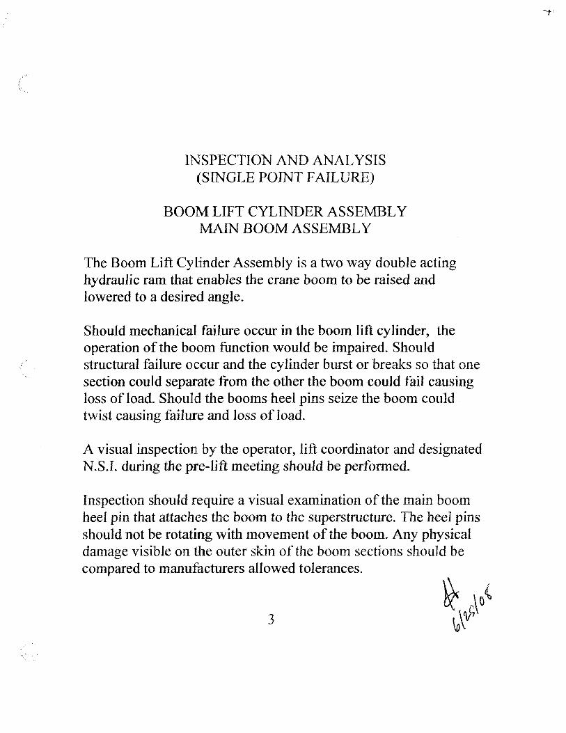
The Boom Lift Cylinder Assembly is a two way double acting hydraulic ram that enables the crane boom to be raised and lowered to a desired angle.
Should mechanical failure occur in the boom lift cylinder, the operation of the boom function would be impaired. Should structural failure occur and the cylinder burst or breaks so that one section could separate from the other the boom could fail causing loss of load. Should the booms heel pins seize the boom could twist causing failure and loss of load.
A visual inspection by the operator, lift coordinator and designated N.S.!. during the pre-lift meeting should be performed.
Inspection should require a visual examination of the main boom heel pin that attaches the boom to the superstructure. The heel pins should not be rotating with movement of the boom. Any physical damage visible on the outer skin of the boom sections should be compared to manufacturers allowed tolerances.
3

INSPECTION AND ANALYSIS (SINGLE POINT FAILURE)
This Crane has multiple telescoping sections for the purpose of extending or retracting the boom. Structural failure of any boom section will cause loss of load. The boom is extended hydraulically and should the hydraulic system fail the boom would remain unchanged, except for the unlikely event of a hydraulic cylinder structural failure.
The boom section should be visually inspected at the pre-lift meeting by the crane operator, lift coordinator, and designated persons on the N. S.1. staff.
The inspection should consist of visually checking to insure all sections are telescoping in the manufacturers required sequence, there is no physical deterioration to the sections. The boom is straight when deployed at working length (twisting, leaning act.)
4
I I

BOOM NOSE GROUP

INDEX
Pages
1 ................................... Item Description
2 ................................... Specifications &Pictorial
3 &4 ............................... Failure Analysis & Inspection
ITEM DESCRIPTION
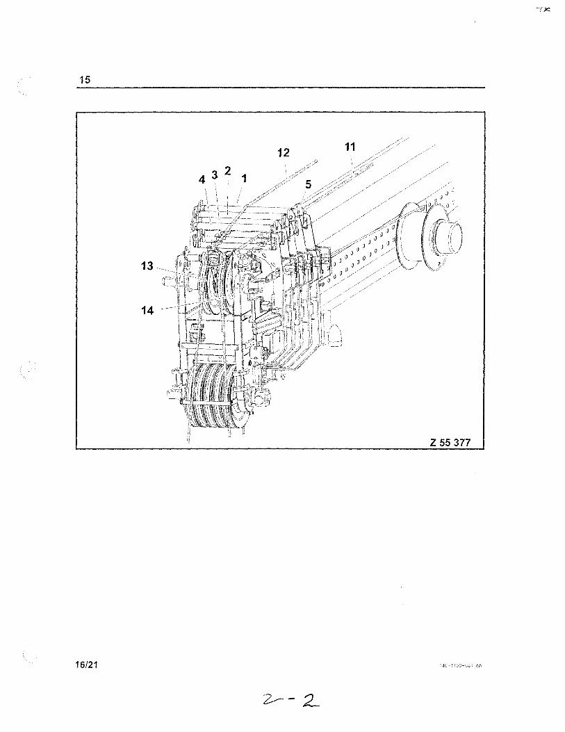
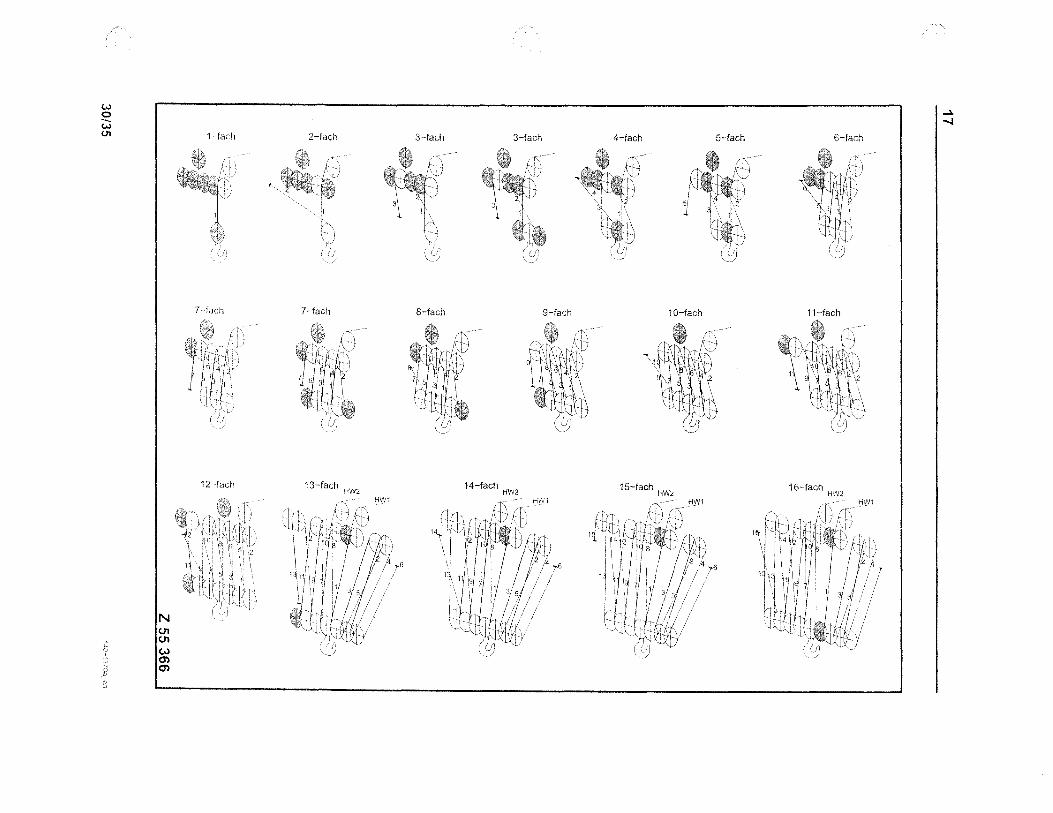
The Boom Nose is located at the outer most end of the telescopic boom. The standard boom point contains 5 sheaves that can be used for up to 10 parts of line. For heavy lifting requiring more than 10 parts additional sheave assemblies can be attached beneath the standard Boom Nose.
The boom nose is also equipped to accept a lattice boom extension.
I

MANUF ACTURER;
TYPE:
CAPACITY
TERREX - DEMAG
FIXED
MULTIPART
LATTICE EXTENSION COMPATABLE
TWO HOIST LINES
16 PARTS
15
12 11
13~1
14 ~-,
Z 55 377
16/21

21
E2 E1
\
1 ,
Ir:t"--' -I
I
2
4
Z 200183
12/13

21
8
~-"C"
"0" 1b
"C"
Z 200185
6/13
17
Z 55 367
32/35 '4C
w <:) -W <J1
N <J1 <J1 W CJ') CJ')
l~fach
12 "fach
2-fach 3-fach
7-fach 8-fach
13-fach HW2
3-fach 4-fach
9-fach 10-fach
14-fach HW2 15-fach HW2
5~·fach 6-fach
11-fach
16-fach HW2
.... ~
INSPECTION AND ANALYSIS
tJPPER SHAFT
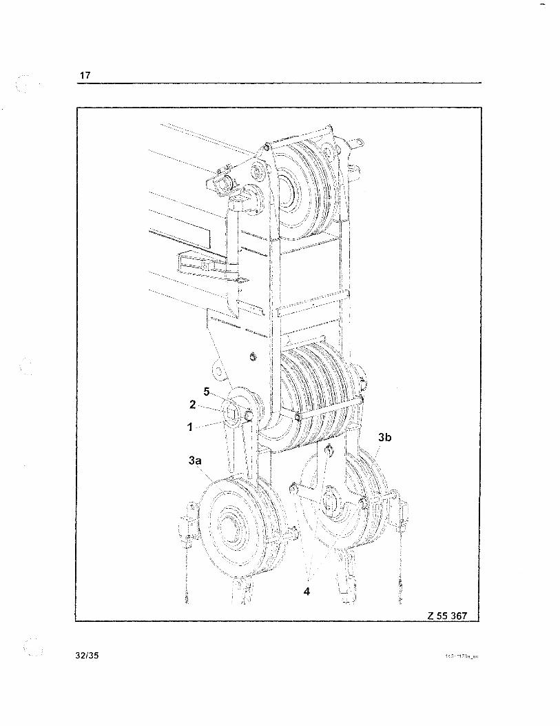
The Upper Shaft holds the upper sheave assembly in the Boom Nose. Failure of this shaft will not cause loss of load but will allow the load to drop one to two feet.
This shaft should be visibly inspected by the crane operator, lift coordinator and designated person on the N.S.I. staff.
The inspection should include examination of all guards and pins, checking sheaves for vibration or wobble, insuring no unauthorized repair has been conducted. Disassembly is not required for this inspection.
3
INSPECTION AND ANALYSIS
LOWER SHAFT
The lower shaft holds the lower (main) sheave assembly in the Boom Nose. Lifts involving mUltiple falls Up to 10 parts can be used with the sheave assembly mounted on the lower shaft. Failure of the lower shaft will cause loss of load by allowing the lower sheaves to escape the Boom Nose and the load cable to unreeve itself.
The inspection of this shaft should insure that all pins and cable guides are in place. Sheaves should turn freely and not exhibit vibration or wobble. The Boom Nose should be free from distortions and not exhibit signs of welding modifications or unauthorized repairs.
This item should be inspected by the operator, the lift coordinator, and the designated N.S.I. person at the pre lift meeting. Disassembly is not required.
4
HOIST GROUP

INDEX
Pages
1 ................................. ,. Item Description
2 &3 .............................. Specifications &PictoriaI
4 &5 ............................... Failure Analysis & Inspection

TEREX-DE~1AG HOISTING SYSTEM
The Terex-Demag crane utilizes a hydraulically controlled hoist system. Failure of anyone single internal component can not cause loss of load. Power to the winch is supplied by an attached hydraulic motor. A combination of hydraulic and electrical power must be present or the load will remain stationary. The winch uses a disc-type brake that is pressure released.
The 'winch engages a sprag clutch to cause a planetary gear system to operate the winch in the up or down direction. The spag clutch can not engage in the absence of pressure. Should engine, pump, piping, valve, or electrical failure occur, the sprag clutch vvill not be engaged, the brake will not release, and the hoist and or load will be held stationary.
The planetary system consists of a single gear ( sun gear) that po\vers the hoist and drum in the up\vard direction. In order to lower the load, the sprag clutch is engaged to hold a series of free floating or rotating gears (planetary gears) in a stationary position. This causes the planetary gears to drive the vvinch drum in the down direction.
Should the disc-brake fail the load will not move due to the above system. The brake provides a holding function and is not intended to provide a controlling function. Load control and speed is provided by control valves that regulate pressure and flow of the hydraulic fluid. With brake failure in the stationary position the load could not move without the control valves failure and then due to restricted flo\v ports or detents, the load would lo\ver slowly. While in motion the load is controlled by hydraulic
pressure in both the up and down positions and the load will remain stationary when the operator returned the control lever to the neutral position closing the control valve.
If electrical failure should occur the system will not operate due to the cranes load moment indicator. The LMI controls all crane actions and ,NiH not allow electrically operated pilot valves to open.
Should hydraulic lines or piping or pumps fail the loss of pressure and flow \-viII render the hoist inoperative.
Modem hydraulic mobile cranes do not have redundant braking systems such as those found on overhead traveling cranes or gantry cranes. The design of hydraulic hoist makes them unnecessary.

04/30/2008 07:52 4107422587 AERIAL CRANE CUSTOM
27572812
I B 7292
05
18
09
EM HW1 1=54 MIT 0211770 P14100
MOUNTING HOIST GEAR 1
~07 17
~ (~
06 ? I"-B-793-1--'11
13 02
978
PAGE 03 57
WTEREX DE MAG
03

AI::J<l AL Ct<ANt:. CU~ I ur.,
27572812 EM HW11=54 MIT 0211770 P14100
MOUNTING HOIST GEAR 1
Pos Ident Idx Menge Text Amount
01 27572912 - 1 VM HW 1=54 MIT SEll 021 1770 305M U Fin
PRE ASSEMBLY HOIST GEAR WITH ROPElFlnlN
02 27572712 - 1 VERSTElLMOTOR ABVM 140 HD2D/63W.vZB 0108 ,
AElVM 140 HD2D/63W-VZB 0109
03 27434012 - 1 SENKBREMSVENTIL CINDY 258
LOWERING BRAKE VALVE CINDY
05 64596240 - 1 SCHLEIFRINGKOERPER GEKAPSEL T
ROTARY JOINT HOIST
06 0022Q012 A 1 INOUKl'IONSSCHAL TER
INDUCTION SWITCH
07 61294940 - 1 LAGERUNG
SUPPORT
06 59105140 C 1 TRAGROLLE
TOP ROLLER
09 30202412 - 1 LAGERHAl TERUNG
BEARING SUSPENSION
10 30202512 - 1 LAGERHAl TERUNG
BEARING SUSPENSION
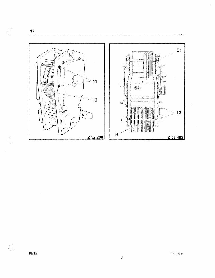
11 66936840 3 SEILROLLENSCHUTZ -ROPE PROTECTION
12 58853340 A 1 ;rr HW-SEILBEFESTIGUNG FUER SElL D21
ROPE FIXING HOIST GEAR
13 51007098 11 SECHSKANTSCHRAU8E -HEXAGON SCREW
14 50063498 - 4 SECHSKANTSCHRAUBE
HEXAGON SCREW
15 1252()4S9 6 SECHSKANTSCHRAUBE
HEXAGON SCREW
16 55105240 2 KLAPPSTECKER -
FORE LOCK ~-
979
PAGE 1214
!;jITERet DEMAG

04/30/2008 07:52 4107422587 AERIAL CRANE CUSTOM
27572812 EM HW1 1=54 MIT 0211770 P14100
MOUNTING HOIST GEAR 1
Pas Ident Idx Menge
Text Amount
17 51043298 ~
14 ZVUNDERKOPFSCHRAUBE
CYLINDER HEAD BOLT
18 34050799 - 14 SCHEIBE
DISC
19 50986296 - 2 SECHSKANTMUTTER
HEXAGON NUT
20 51068596 4 SECHSKANTSCHRAUBE -HEXAGON SCREW
21 50990898 - 4 SECHSKANTMUTTER
HEXAGON NUT
22 34047099 4 SCHEIBE -DISC
23 31913699 4 ZVUNOERKOPFSCHRAUBE -CYLINDER HEAD BOLT
24 50986998 - 4 SECHSKANTMUTTER
HEXAGON NUT !
25 34050099 - 4 SCHEIBE
DISC
26 141374912 - 1 SEfLTASCHE FUEA SElL 021
ROPETASCHE FOR ROPE 021
27 24073312 1 HALTER HY ROHRE -BRACKET HYO TUBES
28 J
12502199 2 SECHSKANTMUTTER -I HEXAGON NUT
PAGE 05
gJTEREX DEMAQ

A~~lAL C~ANE CUSTOM PAGE 05 G::><
27572912 ... VM HW 1=54 MIT SElL 021 1770 305M U FITT ~ TEREX PRE ASSEMBLY HOIST GEAR WITH DEMAG ROPEIFITTIN
981
i
411::1/422587 AERIAL CRANE CUSTOM PAGE 137 ~
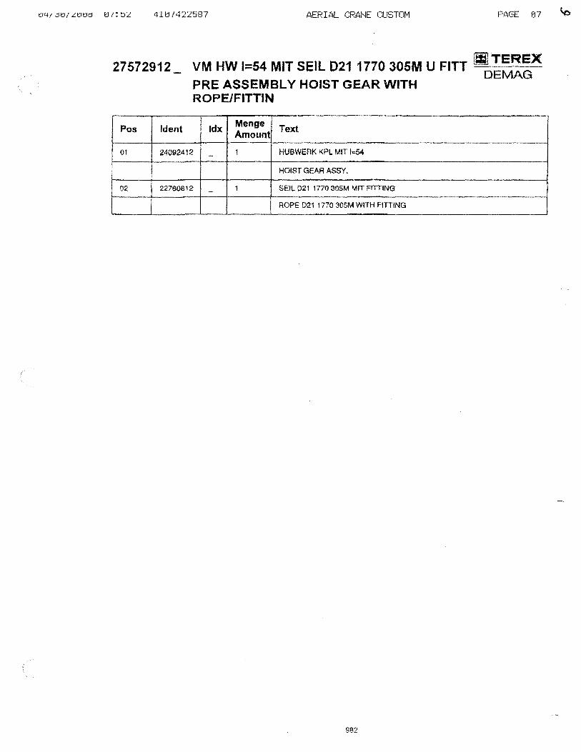
27572912 VM HW 1=54 MIT SElL 021 1770 305M U FITT !ilD~=~X PRE ASSEMBLY HOIST GEAR WITH ROPEJFITTIN
Pos Ident Idx Menge Text Amount
01 24092412 - 1 HUBWERK KPL MIT 1=54
HOIST GEAR ASSY.
02 22760812 - 1 SEll D21 1770 305M MIT FmlNG
ROPE D21 1770 305M WITH FITTING
982
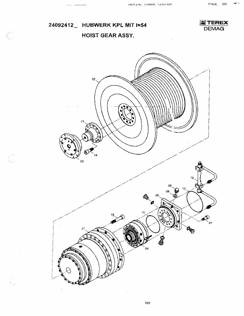
24092412 HUBWERK KPl MIT 1=54
HOIST GEAR ASSY.
03
983
~TEREX DEMAG
//1 / I , I
I j
I , I I
I I
I I
I I
I I
,) ,/

4107422587 AERIAL CRANE CUSTOM
24092412 HUBWERK KPL MIT 1=54
HOIST GEAR ASSY.
Pos Ident Idx Menge Text Amount
01 45207B12 - 1 EINBAUGETRIEBE
"BUILT-IN GEAR
02 45207612 - 1 SEll TROMMEL
ROPE DRUM
03 42061912 A 1 LAGERBUCHSE
BEARING aUSH
. __ ,0.4 .. _._,_ _.45250912 ..J.. M~.
..•. 1. •. ___ • ....J-A..MElLENBflEMSL
DISC BRAKE
05 45251012 - 1 FLANSCH
FLANGE
06 31339599 - 3 SCHRAUBSTOPFEN
SCREW PLUG
07 31915699 - 12 ZYLiNOERKOPFSCHRAUBE
CYLINDER HEAO 80L T
08 33987799 - 3 DICHTRING
SEAL RING
09 43152912 - 1 ENTLOFTER
BREATHER
10 45251112 - 1 O·RING
O-RING
11 45251212 - 1 O-RING
O-RING
12 45251312 1 OlSTANDSANZEIGE -OIL LEVEL GAUGE
13 45086812 1 I FLANSCH -
~ FLANGE
14 31929799 - 12 2YUNDERKOPFSCHRAUBE
CYLINDER HEAD BOLT
I i5 31929199 24 2YUNDERKOPFSCHRAUBE -CYLINDER HEAD SOL T
984
PAGE 0'3 '=:,2
fIjlTEAEX DEMAG
04/30/2008 07:52 4107422587
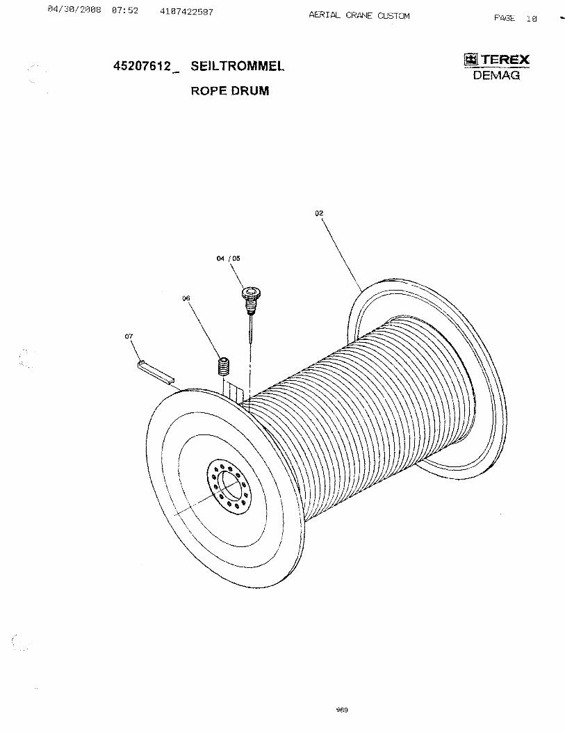
45207612_ SEILTROMMEL
ROPE DRUM
04/05
07
AERIAL CRANE CUSTOM
02
989
PAGE Hl
~TEREX DEMAG

04/30/2008 07:52 4107422587 AERIAL CRANE CUSTOM
45207612 SElL TROMMEl
ROPE DRUM
Pas Jdent Idx Menge
Text Amount
02 45251512 1 SEll TROMMEl -ROPE DRUM
04 45086612 - 1 INITIATOR
PROXIMITY SWiTCH
05 45086712 , KABELDOSE -JOINT BOX
06 32516199 - 4 GWD·STIFT M16X 35
07 420139512 1 KlEMMSCHIENE -
CLAMPING RAIL
990
PAGE 11 c.S
II1ITEREX DEMAG

4LtcJ{4LL:Jt:lf
42061912A LAGERBUCHSE
BEARING BUSH
04
991
WTEREX DEMAG
10

42061912A LAGERBUCHSE
BEARING BUSH
Pos Ident Idx Menge
Text Amount
02 31891489 6 ZYUNDERKOPFSCHRAUBE -CYLINDER HEAD BOLT
03 45086912 - 1 ~INSCHRAUBNIPPEL
NIPPLE
04 45081012 - 1 DUACHGANGSDECKEL
THROUGH LID
05 45087112 - 1 WELLENDICHTRING
AOT ARY SHAFT SEAL
00 45087212 - 1 l.,AGERBUCHSE
BEARING BUSH
07 45087312 1 RILLLENKUGELLAGER -
ROLLER BEARING
08 34267599 - 1 SICHERUNGSRING
CIRCLIP
09 45087412 1 WELlENDlCHTRING
ROTARV SHAFT SEAL
10 78064813 - 1 STECKER
PLUG
99:2
rH<.:lI:: • .L-:l b
fWITEREX DEMAG

45250912 LAMELLENBREMSE
DISC BRAKE
09
08
993
WTEREX DEMAG
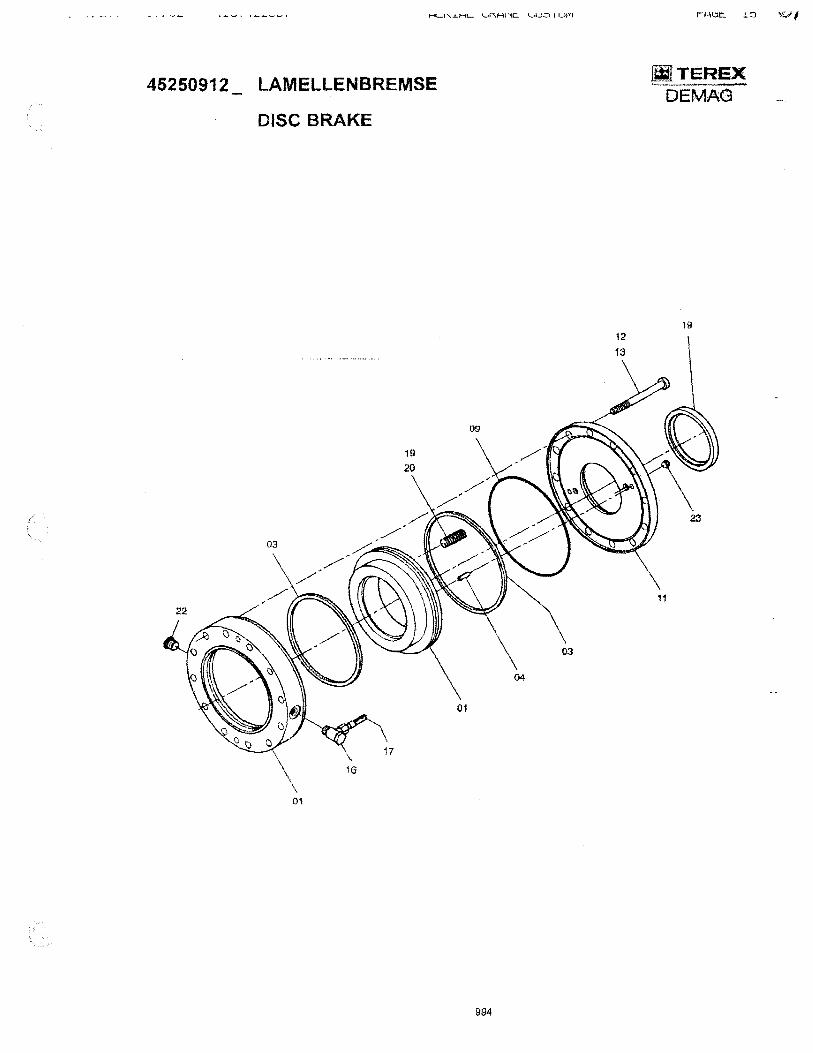
45250912 LAMELLENBREMSE
DISC BRAKE
01
994
~T~EX DEMAG
19

45250912 _ LAMELLENBREMSE
DISC BRAKE
PO! Ident !,dX I ~:O~~t! Text
995
rH<.:lc:. 1.D ,V
]jjTEREX DE MAG

45251312
09
03
09
AERIAL CRANE CUSTOM
OLSTANDSANZEIGE
OIL LEVEL GAUGE
~
/'
12
13
10~-10
02 /~ 09
07
08
06
03
04
996
10 11
5
06
PAGE 17
~TEREX DEMAG
I
4107422587 AERIAL CRANE CUSTOM
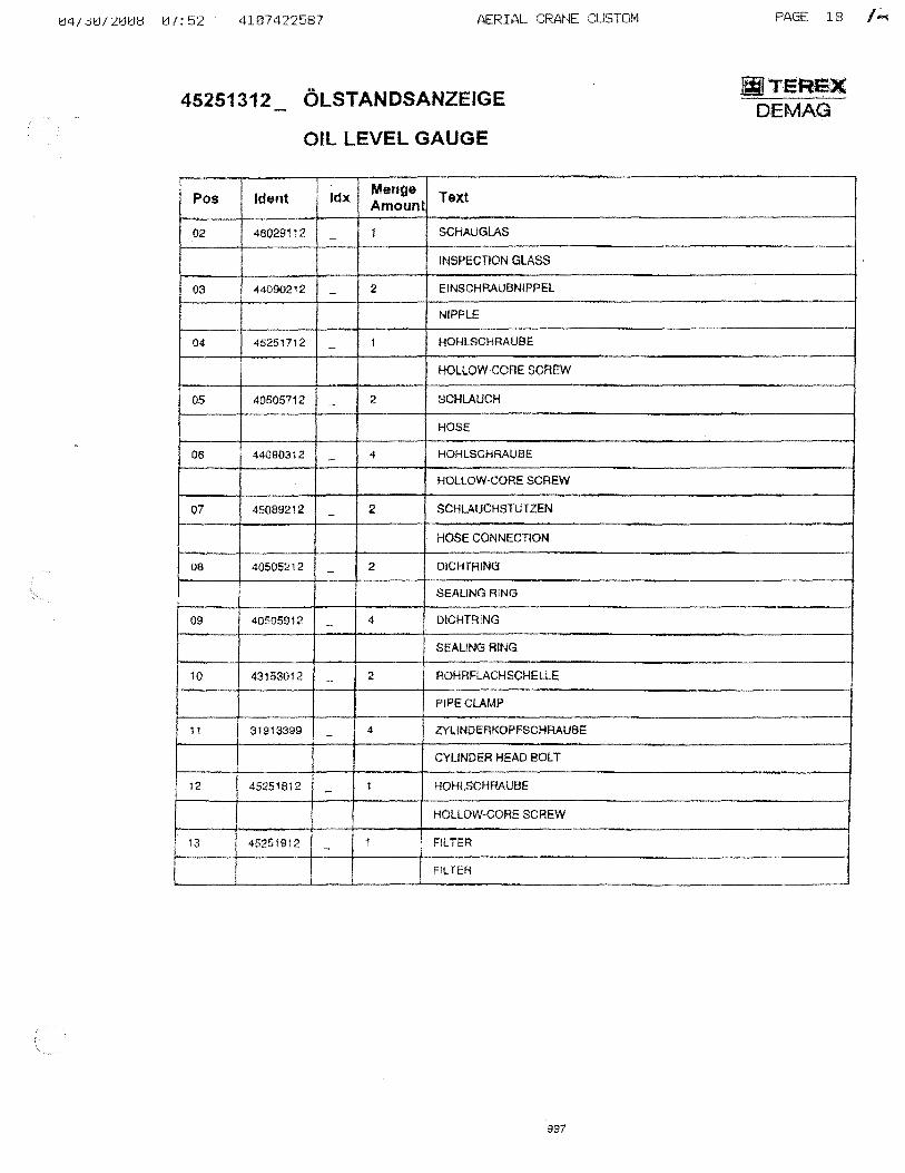
45251312 OlSTANDSANZEIGE
Oil lEVEL GAUGE
Pos Ident Idx Menge Text Amount
02 48029112 - 1 SCHAUGLAS
INSPECTION GLASS
03 44090212 - 2 EINSCHRAUBNIPPEL
NIPPLE
04 45251712 1 HOHlSCHRAUBE -
HOLLOW-CORE SCREW
05 40505712 - 2 SCHLAUCH
HOSE
06 44090312 - 4 HOHlSGHRAUBE
HOllOW-CORE SCREW
07 45OB9212 2 SCHLAUCHSTUTZEN -
HOSE CONNECTION
08 40505212 - 2 DICHTRING
StALING RING
09 40505912 4 DICHTRING -SEALING RING
10 43153012 2 ROHRFlACHSCHEll-E -
PIPE CLAMP
11 31913399 - 4 ZYLINDERKOPFSCHRAUBE
CYLINDER HEAD BOLT
12 45251812 - 1 HOHlSCHRAUBE
HOLLOW-CORE SCREW
i 13 45251912 '1 FilTER -
I FiLTER
997
PAGE 18 I"""
~TEREX DE MAG
04/30/2008 07:52 4107422587 AERIAL CRANE CUSTOM PAGE 19 1:
27572712 VERSTELLMOTOR A6VM 140 HD2D/63W-VZElljJTEREX - 0108 DEMAG
ASVM 140 HD2D/63W-VZB 0108
09
04
~ I
1-10
06
01
02
998

I
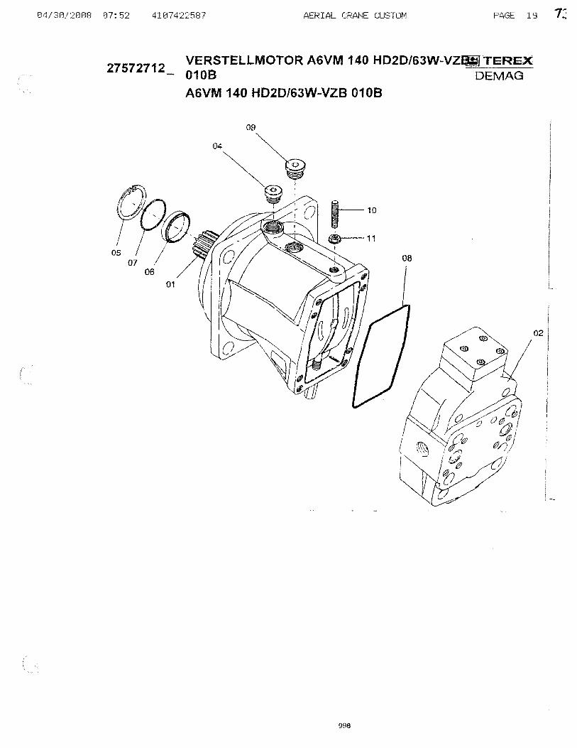
27572712 VERSTEllMOTOR A6VM 140 HD2D/63W-VZaliTEREX 0108 DEMAG·
A6VM 140 HD2D/63W-VZB 0108
Pas Ident Idx Menge Text Amount
01 41543912 - 1 TRIEBWERK
POWER UNIT
02 4100361;2 - 1 VERSTELI..UNG. KPL.
ADJUSTMENT ASSY.
04 08766740 - 1 Vf,;RSCHLSHR M22X1,5
05 34266599 1 SICHERUNGSRING -CIRCllP
06 75808273 1 WELLENDICHTRING -SHAFrSEAL
07 75453300 - 1 SCHEIBE
DISC
08 51491598 - 1 O-RING
O·RING
09 31329699 - 1 VERSCHLSHR M26X1 ,5
SCREW PLUG M26Xl.5
10 41 307812 - 1 GEWINOJ;STIFT
THREADED PIN
11 96476700 - 1 BUNDMUTTER
FLANGED NUT
999

4.LtJf4LL:Jts{
41543612 TRIEBWERK
POWER UNIT
l". . "
"
03
02
A~~lAL C~AN~ CU~IUM
1000
'1 I
• J
PAGE 21 7~
IjiTEREX DEMAG ~- ,
I
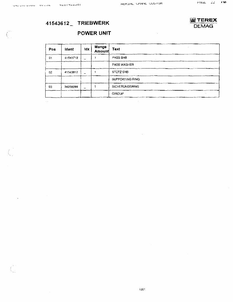
41543612 TRIEBWERK
POWER UNIT
Pos Ident Idx Menge Amount
01 41543712 1 -
02 41543812 1 -
03 34250099 1 -
Text
PASSSHB
PASS WASHER
STOTZSHB
SUPPORTING RING
SICHERUNGSRtNG
CIRCUP
1001
[ijITEREX DEMAG

AERIAL CRANE CUSTOM
41603612 VERSTELLUNG, KPL.
ADJUSTMENT ASSY.
02
07~'
~ f I
05 ~ "---()
03----<!>
I
/
I ,
/' /' /
I / I
1002
01
06
PAGE 23 I I
lWlTEREX DEMAO"
09
~08
4107422587 AERIAL CRANE CUSTOM PAGE 24
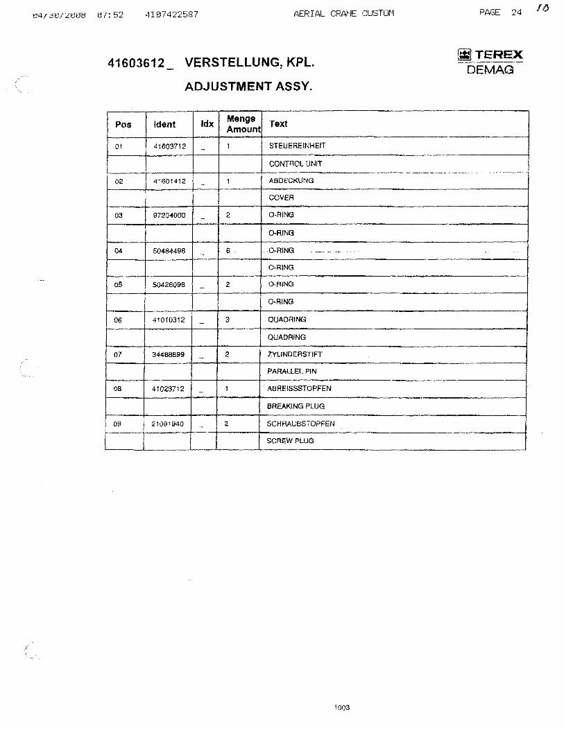
41603612 VERSTELLUNG,KPl.
ADJUSTMENT ASSY.
~TEREX DEMAG
Pos Ident Idx Menge Text Amoun1
01 41603712 - 1 STEUEREINHEIT
CONTROL UNIT ,,_~, _w ____ ._~,.~ _. __ ._, . . ~'-'----
02 41601412 1 ABOECKUNG
COVER
03 97204000 - 2 O-RING
Q..RING
04 50484498 6 - . a-RING .. -,- .-~ .. -O-RING
05 50426098 - 2 O-RING
O·RING
06 41010312 - 3 QUADRING
QUADRING
07 34488899 2 Z'YLINDERSTIFT -
PAAALLI::L PIN
08 41023712 1 . ABREISSSTOPFEN -BREAKING PLUG
09 I 210911140 - 2 SCHRAUBSTOPFEN
I SCREW PLUG
1003
16

04/30/2008 07:52 4107422587 AERIAL CRANE CUSTOM
41603712 STEUEREINHEIT
CONTROL UNIT
I
1004
PAGE 25
_TEREX DEMAG
1
~ 4
1'/

,....,'-I,\..I.H'- ...... I"H' '1'- VW-.I I WI'I
41603712 STEUEREINHEIT
CONTROL UNIT
Pos Ident Idx M&nge Text Amount
01 50138098 1 O-RING
O-RING
02 25598540 - 1 SCHRAUBSTOPFEN
SCREW PLUG
03 96466300 1 BtJNOMljTTEA -FLANGED NUT
04 43103173 5 STECKER -PLUG
05 50137998 - 1 O·RING
O,AING
06 41801612 - 1 BUNDMtJTTER
FLANGED NUT
1005
!WITEREX DEMAG

04/30/2008 07:52 4H17422587
41601412 ABDECKUNG
COVER
I
1
AERIAL CRANE CUSTOM
1006
PAGE 27
~TEREX DEMAG
2

04/30/2008 07:52 4107422587
41601412 ABDECKUNG
COVER
Pas Ident Idx Menge Amount
01 5059489B 1 -
02 25598540 - 1
AERIAL CRANE CUSTOM
Text
O-RING
O·RING
SCHRAUBSTOPFEN
SCREW PLUG
1007
PAGE 28
alTERE)[ DE MAG

04/30/2008 07:52 4107422587
59105140C TRAGROLLE
TOP ROLLER
03
AERIAL CRANE CUSTOM
1008
PAGE:L':l 0 ....
~TEREX DEMAG
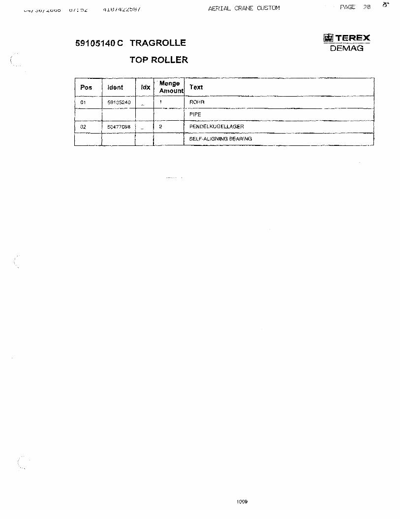
59105140 C TRAGROLLE
TOP ROLLER
Pos Ident Idx . Menge Amount
01 59105240 1 -
02 50477098 - 2
AERIAL CRANE CUSTOM
Text
ROHR
PIPE
P~NDELKUGELLAGER
SELF-ALIGNING BEARING
1009
PAGE 313 l5"
/WITEREX DEMAS

RcKiRL ~KRNc ~U~IUM
58853340 A ZT HW .. SEILBEFESTIGUNG FUER SElL 021 Jill TEREX DEMAG
ROPE FIXING HOIST GEAR
02
1010

DRUMS AND WINCHES
ITEM DESCRIPTION
The Hoist Mechanism consists of a winch or drum, hydraulic motor, and load breaking system to slow or stop the movement of the load.
The hydraulic motor rotates the drum either raising or lowering the load with the installed wire rope and hook block assembly.
I

HOIST MOTOR COMPONENTS
The Hoist Motor provides the means of moving the drum in order to raise and lower loads.
This motor has restricted flow valves and internal planetary gears to control the lowering and hoisting. There are no single failures in this system.
Both the hydraulic and electrical systems have circuit breakers and check valves that will prevent accidental loss of load should electric or hydraulic pressure is lost.
The component illustrations in this report, while not exact, are similar in their make up and have been submitted to clarifY how the hoist motor functions.
4

INSPECTION AND ANALYSIS SINGLE POINT FAILURE ANALYSIS
Each hoist located on the rear upper superstructure is secured by high strength screw caps. Not a single point failure but a visual inspection of the screw caps should be done by the crane operator or some other qualified person on the lift team during the pre-lift meeting.
5

OUTRIGGER GROUP
INDEX
Pages
1 ................................... Item Description
2 & 2A ........................... Specifications &Pictorial
3 &4 ............................... Failure Analysis & Inspection

ITEM DESCRIPTION
OUTRIGGERS
The Outrigger System uses two stage horizontal beams and vertical jacks to level the crane and stabilize the crane by increasing the tipping axis for all quadrant of operation. The outrigger system also provides a means to limit the ground pressure at each tipping aXIS.
The outrigger system on this crane is hydraulically powered.
1
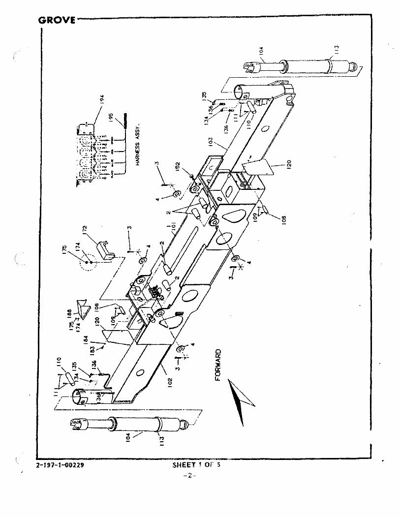
GROVE-----------------------------------------
-,ro-'
1-. ---..
2-197-1-00229 SHEET 1 Of 5
-2-

__ --------------------------------------GROVE
I
SHEET 2 OF 5 -3-
2-197-1-00229
'.

INSPECTION AND ANALYSIS
CYLINDER ASSEMBLY
The cylinder assembly is the vertical jacking portion of the Outrigger System. It provides the operator with the means to level and therefore stabilize the crane.
If there is a total structural failure of the cylinder assembly, loss of load would occur.
The inspection should consist of a visual examination of the vertical jacking cylinders for defects such as leak down. Outriggers employ a holding valve to prevent the jacks from leaking, however if the valve should become contaminated the valve could slowly leak down possibly causing a tipping condition and loss of load would occur. lacks should be centered and pin on the outrigger pads. Insure that all pads are supported over 100 % of the pad area or span loading could occur causing the pads to fail at 50% capacity.
The cylinder should be inspected at the pre-lift meeting by the crane operator, lift coordinator and designated persons on N.S.I. staff.
3

INSPECTION ANALYSIS
BEAM ASSEMBLY
The beam assembly is hydraulically powered and extends out away from the crane carrier. This provides greater stability while lifting loads.
If there is a total failure in the beam assembly, loss of load will occur.
The inspection should consist of insuring that there are no structural defects to the beams such as cracked welds, bending or twisting of the beams. Close attention should be paid to the beam housing for diagonal cracks due to structural overloading.
The beam assembly should be inspected during the pre-lift meeting by the crane operator, lift coordinator and qualified persons on the N.S.I. Staff
4

7
ENGINE GROUP

INDEX
Pages
1 ................................... Item Description
2 .................................... Specifications
3 .................................... Pictorial

ITEM DESCRIPTION
ENGINE
Hydraulic Pressure and Electrical Power are provided through hydraulic pumps and electrical generators which are driven by the cranes diesel engine.
Should total engine failure occur all action will be stopped and the load will remain stationary until engine power is restored?
No loss of load will occur should engine power be lost.
1
MANUF ACTURER:
TYPE:
DaimlerChrysler OM 904 LA
KW,1800Nm
Diesel
Internal Combustion
2

~ I I N'" I N
C) -N
't --CD jI
X o :t U)
·t~ ... _ .... _
( -) -29 30 31 38
19 -1-"""-.: ' .. ~,
". 1", ~ :. ~
~'i II " ~ )1fti:,,·1Jj
US7
- "tEw SMOwtl\lo An rAl« HOO< ......
123 110 UI. 160 IUS
til
a
f 13 3
29
¥J~ 37
I .' . I.' , . . .' '\ I i 10 \ II :
il-. """. .... }
"IEW I,",,' -.. ..
[
" =::='~~~ .-----• "'9 ~:r:::1 \ J ,
• ".... I' I t:tJ ~:: --/-I-l--CIII~. ':'"] 11 !j · J_m~ · (
IOC_-r : I 131 I I I 138 l 1···_
[-_. '" -
I .--. t-·,-12
1-20 21
113
• . . ,L •. __ .•• __ _
~ 22 23
ItO III
104 124
161 156 116 105
175
166 167 164 165
l09
, ~ 4C
c

ELECTRICAL SYSTEM

INDEX
Pages
I ................................... Item Description
2 .................................... Specifications
SYSTEM ANALYSIS
ELECTRICAL SYSTEM
The Electrical System of the crane ·works in conjunction with the hydraulic system. Each action requires both hydraulic and electrical activation. No single item will cause loss of load.
If a particular electrical component should fail, that particular function \vould be repaired.
1
IU