educational content management system for math-logical e-learning
TRANSCRIPT
Ahmad Hadi
Educational Content Management System for math-logical e-Learning
Helsinki Metropolia University of Applied Sciences
Bachelor’s Degree
Degree Program in Information Technology
Thesis
3 October 2013
Contents
1 Introduction 1
1.1 Objectives 1
1.2 Requirements 2
2 Theoretical Background 4
3 Methods and Materials 7
3.1 Content Management System 7
3.2 Dynamic-link Library 8
3.3 Database System ADO 9
3.4 COM Technology and ActiveX 11
3.5 Programming Environment 12
4 Results 16
4.1 Overview of the System 18
4.2 Math Tools 24
4.3 Description of the Games 28
5 Discussion 32
5.1 Description of the IDE 32
5.2 The Coding Requirements 34
5.3 The Coding 35
6 Conclusions 40
References 42
Appendices
Appendix 1. Listing of unit DisableWinKeys.
Appendix 2. Listing of unit QuizeSystem.
Appendix 3. Structure of the software system.
Appendix 4. Listing of unit CalcExpress.

1
1 Introduction
The primary objective of this project is to design and develop a software system for math-
ematics and logic education. The software is aimed to improve math and logic skills of
users. Moreover, the software should allow teachers or any math or logic experts to
change or add tasks. Additionally the objectives of this project are the practical imple-
mentation of my theoretical knowledge and to develop my programing skills. During the
work on the project it is possible to gain experience in the software development field
and to improve writing and presentation skills.
In general the Content Management System (CMS) is a software platform. The purpose
of a CMS is to manage and to process the content. The content is very often defined as
specific data. In this project the content consists of logic and math tasks and correspond-
ing solutions. An Educational Content Management System for math-logic e-learning
which can operate on Windows platform is the target of this software project.
Embarcadero Rapid Application Development Studio (RAD Studio) allows fast and very
efficient development of native Windows applications. The RAD Studio includes the Del-
phi computer language which is convenient for math and logic operations. Therefore the
RAD Studio was chosen as an integrated development environment for this project.
1.1 Objectives
This software project should have an installer for a desktop or a laptop Windows platform.
Additionally it should be manageable, which means that tasks or the content of the sys-
tem should be defined by teachers because it is a Content Management Systems (CMS)
for math-logical e-learning. The web development CMS became popular in the last dec-
ade due to the exponential growth of demand for websites. A majority of the CMS are
dedicated to simplify web application development. An example of a popular Web CMS
is the Joomla. Big companies and organizations such as eBay, IKEA, MacDonald’s, UN
are using the Joomla CMS for their websites according to the home page of the Joomla
foundation www.Joomla.org. [7, 2]

2
The definition of the Content Management System in this project is different from the
conventional definition. The first difference is that, this software project is not for web
development but it is for simplifying development of the educational e-learning software.
The second important difference is that the CMS for e-learning can be installed stand-
alone on a computer and it is able to operate without the Internet. The Internet connection
is used to fetch updates or to upgrade the software. One of the most important parts of
any software project is planning. The purpose of this project is to learn how to develop a
software system, to learn how to plan, to manage and to solve all kind of related problems
concerning project development.
1.2 Requirements
The software should consist of quizzes, educational and brain developing games. The
deployment of this project via a website was a part of the requirements.
The basic requirements to this software project were:
portability
reusability
user-friendly interface
modern UI design
Internet connection.
The first requirement means that the software should be able to run on different operating
systems. In this project the base platform was Microsoft Windows. For the Linux-like
platforms the software can be recompiled in the Lazarus IDE. Also it is possible to de-
velop a Web-based application which would improve the portability of this software sys-
tem.
The second requirement states that this software should be reusable. The purpose of
this software depends on its content. For example, with the math content it can be used
as math educational software or with the physics content it can be used as physics edu-
cational software. However, the best use of this software will be achieved if the content
is related to math or logic, for instance math, algebra, discrete math, geometry, logic
contents will be more suitable for this CMS than other type of contents.
3
The user-friendly interface item in the list refers to the type of an interface which is simple
and intuitively understandable for any user. Also the colors and order of elements are
convenient and reasonable. A modern UI should have modern features. It should be
suitable for the recent trends and demands of the UI design. For example, it would be
sensible to implement the Microsoft Metropolis (Windows 8) style for the UI in this project
because it is new and popular. The Internet connection is one of the most important and
initial features of the contemporary software applications. Often the Internet connection
is used to fetch updates or to send data to the server. Another use of the Internet for
modern software systems is remote database systems.
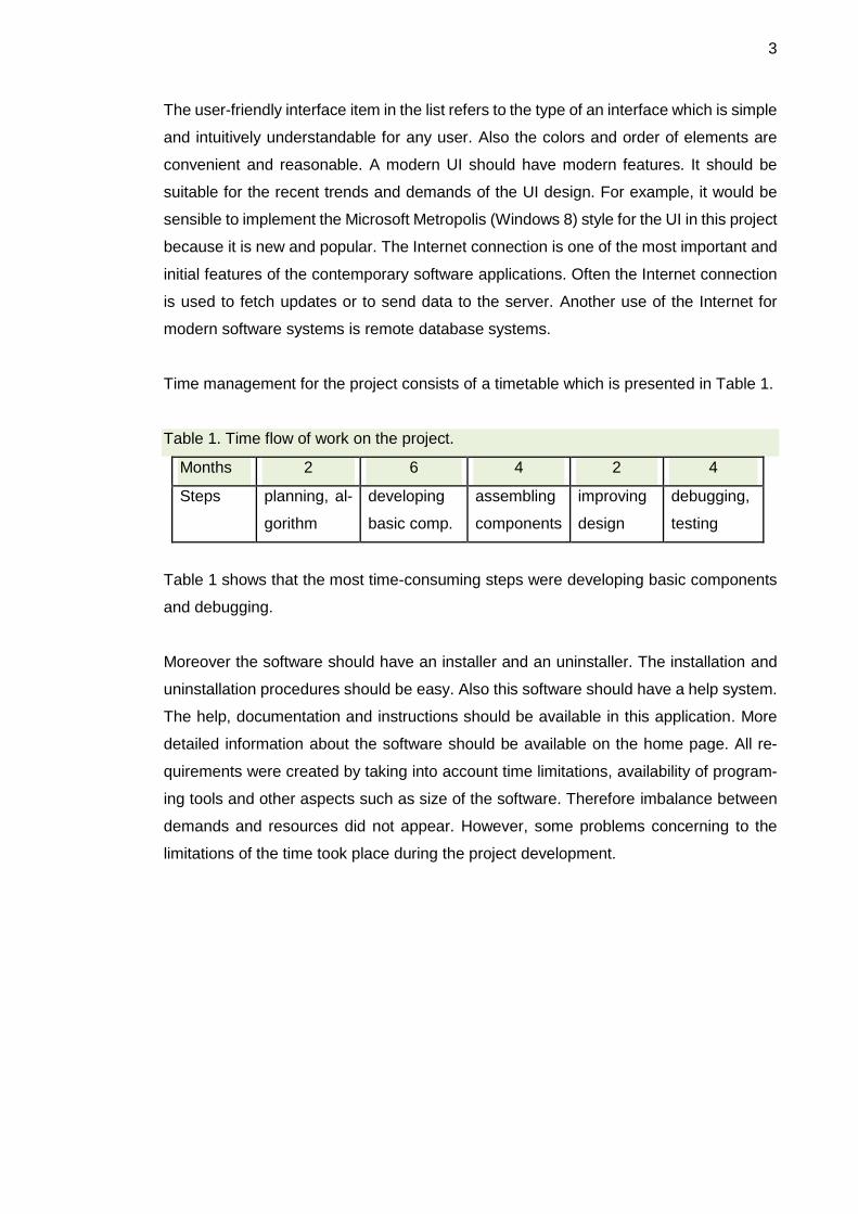
Time management for the project consists of a timetable which is presented in Table 1.
Table 1. Time flow of work on the project.
Months 2 6 4 2 4
Steps planning, al-
gorithm
developing
basic comp.
assembling
components
improving
design
debugging,
testing
Table 1 shows that the most time-consuming steps were developing basic components
and debugging.
Moreover the software should have an installer and an uninstaller. The installation and
uninstallation procedures should be easy. Also this software should have a help system.
The help, documentation and instructions should be available in this application. More
detailed information about the software should be available on the home page. All re-
quirements were created by taking into account time limitations, availability of program-
ing tools and other aspects such as size of the software. Therefore imbalance between
demands and resources did not appear. However, some problems concerning to the
limitations of the time took place during the project development.
4
2 Theoretical Background
The IDE is an abbreviation for Integrated Development Environment. In some sources it
is also called as Integrated Design Environment or Integrated Debugging Environment.
In this report the initial meaning of this term is adopted. The IDE is an enhanced and
featured editor for software development. The IDE Embarcadero RAD Studio is used for
development of this project. [8, 1]
The UML is an abbreviation for Unified Modeling Language. UML is a multi-purpose
modeling language for software engineering. It can be used for software design and data
modeling. There are possibilities (software tools) which allow to translate an UML dia-
gram directly into a ready software product and vice versa. [8, 1]
The Rapid Application Development (RAD) is a software development methodology. The
RAD is a methodology of programming that uses minimal planning in favor of rapid pro-
totyping. The RAD approach significantly increases the speed of software development.
The RAD method was implemented in this software project [8, 1].
RAD methodology consists of the following phases:
business modelling
data modelling
process modelling
application generation and testing
turnover. [5, 1]
The business modeling phase consists of following steps:
to define the business-field and the goals
to collect and classify all related data
to create the first outline and a sketch of the project plan
to create a plan for development and deployment of the software project. [5 ,1]
Data modeling includes a definition of data-types and the creation of tables. The next
step is to create connections between tables and a definition of key-fields. In this project
the Unified Model Language (UML) was used for data modeling. The data modeling is
the initial phase of the creation of a database [8, 1].
5
The application generation and testing consists of:
fast prototyping
coding
implementation
collection of data related to the bugs and further development
returning back to fast prototyping. [5 ,1]
The fast prototyping is replacing the planning phase of software development. At the
same time prototyping is a coding process. Eventually this will save time and effort be-
cause it is a combination of two processes ongoing in parallel. Also fast prototyping is
helpful for finding bugs before the final phase of coding. The RAD method is periodic and
iterative. It allows to deploy fast and then periodically update, upgrade and improve the
application. It is one of the most efficient ways of software development [5,152]. The
RAD method increases the speed of software development and reduces costs.
The CMS is an abbreviation for Content Management System. The term CMS itself is
relatively new and often refers to web software development. In terms of web develop-
ment it is a ready website with an open source and a complete admin-side. However the
use of the CMS is not limited only to web applications. Different types of CMS are widely
used in various types of software. The common functionality for any type of the CMS is
the management of stored data. The use of the CMS will increase code reusability. This
will save time and effort during software development.
The focus of this project is development of an e-learning CMS or briefly, e-CMS. E-learn-
ing is a type of learning process where the letter “E” or “e” refers to electronic origin.
Usually it is about educational software systems or simply, about electronic books. In
general the e-learning method is becoming more popular due to a set of advantages over
the classic methods.
Component Object Model (COM) is an interface and a software technology which was
introduced by Microsoft in the late 1993. The COM interfaces are implemented in the
several computer languages such as C++ and Delphi [3, 1]. The main idea in this tech-
nology is that programmers can use COM - objects without knowledge of their internal
structure or even computer language. COM presents a binary interface for dynamical
communication between components. It offers reusable methods (procedures and func-
tions) for programmers. [2, 46]
6
The Object Linking and Embedding (OLE) is a technology developed by Microsoft. It
allows an editing application to export part of a document to another editing application
and then import it with an additional content. For example, a table from the Excel can be
embedded into a Word document.
ActiveX Data Objects (ADO) is a software technology for data-access which was intro-
duced by Microsoft in 1996. Basically ADO consists of COM objects for a manipulation
of data in a database. It includes data manipulations such as to update, to delete, to add
new data etc. Additionally it is possible to run a SQL script directly via an ADO-instance.
[2, 6]
Dynamic-link Library (DLL) is Microsoft's implementation of the shared library concept in
the operating system Microsoft Windows. It allows to create fast, lightweight applications
and to use data safely. More details about DLL, ADO and COM are given in subsections
3.3, 3.4 and 3.5.
Object-orientated Programming (OOP) is a programming paradigm (a fundamental style)
that represents concepts as "objects". The objects have data fields (variables, constants,
properties) and associated procedures or functions known as methods. In the Object-
orientated Programming (OOP) the prototypes are abstract presentation of the classes,
methods and fields. An object is usually an instance of a class. A class is an abstract
data-type. Usually it includes templates and descriptions for the methods and fields. The
fields consist of different type of data such as numeric, string or characters. The objects
are used to interact with one another. They are used to design applications and computer
programs. The data fields are attributes (properties) that describe an object. They can
be presented as a constant, variable or any other type of data. The methods are used to
process the fields of an object. Therefore the methods define behavior of an object. C++,
Object Pascal and Java are examples of object-oriented programming languages. Some
computer languages such as Java and C# are pure object-oriented. All variables in the
pure OOP languages are presented as objects. In this case the fields of an object also
are objects with the corresponding methods and behavior. Therefore the processing of
the fields is easy. [8, 1]
7
The main software developing environment for this software project is the Embarcadero
RAD Studio and the database system ADO. The RAD Studio allows to utilize all ad-
vantages of the OOP. The software technologies such as DLL and COM are used in this
project. Additionally the Microsoft Access and Office are used to create the database
and help-system for this project.
3 Methods and Materials
The objective of this chapter is to explain the technical terms which have been used in
this project. Other goals of this chapter are to describe the software developing environ-
ment and the main concepts and additionally to show how this project was carried out in
practice.
3.1 Content Management System
The name of the product is “eCMS”. The letter “e” refers to the first letter of the word
“educational”. For example, the eCMS can be used for the math-logic training, exams
and tests. A web CMS allows, for example to change articles, images, banners, to delete
posts, to change design and rules or site map. The purpose of a website which is based
on a CMS totally depends on the content and the settings of that CMS. Therefore the
purpose of a website can be defined via its CMS settings.
In the same way a purpose of an eCMS depends on the settings and the content. There-
fore the goal of this software system can be set through the content management sys-
tem. The content and settings of an eCMS can be redefined. For example, the math
eCMS can be redefined as educational software for physics or vice versa.
Usually an administrator of website has access to the all options and content of the cor-
responding CMS. Therefore the administrator can change and update the system. For
example, an e-learning website can be transform into a web shop or vice versa. In the
same way the settings of an eCMS are open for teachers or any math-logic experts. They
have full access to the content and settings of the system. An eCMS is desktop software
8
and therefore it contains features which cannot be implemented by using only web tech-
nologies. On the other hand it can use an Internet connection, for example to update the
content or to fetch new tasks.
3.2 Dynamic-link Library
Microsoft technology, which is called Dynamic-link Libraries (DLL) plays an important
role in the development of this project. DLL is Microsoft's implementation of the shared
library concept in the Microsoft Windows. These libraries usually have the file extension
“dll” or “ocx” or “drv” for legacy- system drivers. The ActiveX-controls use the shared
library concept.
Embarcadero Delphi does not need LIB files such as the computer language C++ to
import functions from DLLs and to bind them to an application in runtime. In Delphi the
keyword “external” is used in the function declaration. For example, this is a declaration
of a function which is located in an external DLL file “Funcom.dll”:
function GetResourceAsJpeg(const resname: string): TJpegImage;
external 'Funcom.dll';
The keyword “external” is used before the path to the Funcom.dll. This DLL-file is located
in the same folder as the application itself. Therefore the relative path 'Funcom.dll' is
enough to access and there is no need for an absolute path. However, an absolute path
might work without any problem. In the same way it is possible to have access to any
method or field of the Funcom.dll.
The file formats for DLL are the same as for the Windows EXE files. A DLL file can
contain code, data and resources in any combinations. They provide a mechanism for
the shared code and data. This allows developers of the shared code to upgrade func-
tionality of an application fast and easily without requiring to be re-linked or recompiled.
The code of a DLL module is usually shared among all the processes that use it. There-
fore they occupy a single place in a physical memory and do not take space in the page
file (virtual memory). If the physical memory occupied by a code section is to be re-
claimed, its contents are discarded. Later-on it can be reloaded directly from the DLL file
if it is necessary. In contrast to the public code sections, the data sections of a DLL are
usually private. Therefore each process which uses a DLL has its own copy of all the
9
DLL data. Optionally, the data sections can be made shared, allowing inter-process com-
munication via that shared memory area. However, this may cause problems in the ac-
cess process.
3.3 Database System ADO
Microsoft's ActiveX Data Objects (ADO) is a set of Component Object Model (COM)
objects for accessing data sources. The ADO allows a developer to write programs that
access data without the knowledge of how the database is implemented. In most cases
this will increase the speed of the programming and save time. The use of ADO does
not require knowledge of SQL. However, it is possible to execute SQL commands directly
via ADO procedures. Microsoft ADO contains almost any kind of functions and proce-
dures for manipulating and accessing a database. For example, there are functions for
finding fields, records, updating, deleting, counting and showing size (value) of data field
or record.
Some basic steps are required to access and manipulate data by using the Microsoft
ADO. The first step is to create a connection between an ADO object and database and
a record-set object to receive data [5, 387]. After this it is possible to open the connection.
An open connection allows passing the desired table name or an SQL statement as a
parameter to an ADO method and to do all the planned searching/processing on the
fetched data. Committing any changes to the data can be done by using the following
commands:
Update();
//or
UpdateBatch();
End of working with Microsoft ADO include the closing record-set and current connection:
free();
Close();
Compatibility with many modern database systems is a very important advantage of the
Microsoft ADO. For example, it is possible to use the Oracle Call Interface (OCI) in the
C# after declaration of this:
10
using System.Data.OracleClient;
After this it is possible to work with an Oracle database.
The benefits of the ADO technology particularly in this project or in software projects in
general include the following:
● Easy to use
● High performance
● Control of cursor position
● Complex cursor types
● Synchronous, asynchronous or event-driven query execution
● Ability to return multiple result sets from a single query
● Re-usable, property-changeable objects.
Indeed the main advantage of this technology is that for the use of ADO, the knowledge
of SQL is not needed. After establishing a connection to a DB, all related procedures
(methods) are automatically available for accessing and manipulating data. Therefore it
is easy to use. Another important advantage of ADO is high performance. The perfor-
mance remains high although there is no direct connection to DB but it is via ActiveX-
controls. The cursor in the context of Data Base as the field of computer science means
the position of an active record in the DB system. The ADO system enables to control
the position of a cursor via corresponding procedures. It includes several types of cursors
such as batch, server and client-side cursors.
In the ADO technologies the execution of a query can be event-driven. Therefore the
order of data-exchange can be controlled. It is possible synchronously or asynchronously
to exchange data between an application and a DB system. All objects of the ADO sys-
tem are reusable because they are derived from AciveX-objects. The properties of the
ADO objects can be changed via code. Therefore there is access to read or write the
properties (fields) of an ADO object. The Microsoft ADO has an advanced record set,
cash management and flexibility because it works with existing database technologies
and all OLE DB providers. Information about Object Linking and Embedding (OLE) tech-
nology is provided in the section 3.1. The ADO technology has an excellent error trapping
of the system, so the use of this technology is beneficial. The disadvantages of ADO
technology refer to portability issues. The implementation of the ADO technology can be
11
only on the Windows platform. The new version of ADO is ADO.NET which can operate
only if .NET framework is installed. This framework makes ADO more portable among
the different versions of Windows platforms.
3.4 COM Technology and ActiveX
The Microsoft Component Object Model (COM) technology and ActiveX are widely used
in this project. The main purpose of these technologies is to increase the code-reusability
and speed up the software development process. The COM technology in the Microsoft
Windows-family of operating systems enables software components to communicate be-
tween each other. The COM is used by developers to create re-usable software compo-
nents. Also it allows to link components together and to build applications. The Microsoft
COM technology enables the use of Windows services. The COM objects can be created
with a variety of programming languages. Object-oriented languages such as C++ and
Delphi provide programming mechanisms that simplify the implementation of COM ob-
jects. The family of COM technologies includes COM+, Distributed COM (DCOM) and
ActiveX® Controls. [1, 1]
Microsoft provides the COM interface for majority of Windows applications and program-
ming interfaces such as Direct Show, Media Foundation, Packaging API, Windows Ani-
mation Manager, Windows Portable Devices and Microsoft Active Directory (AD). The
COM is used in Microsoft applications such as Microsoft Office family of products. For
example, COM OLE technology allows the Microsoft Word documents to be dynamically
linked to data in Microsoft Excel spreadsheets. Furthermore the COM Automation tech-
nology allows users to build scripts in their applications to perform repetitive tasks or to
control one application from another. [1, 4]
The ActiveX is a framework for defining re-usable software components. It is not
bounded to a certain computer language. ActiveX controls are mini program-building
blocks. They can be used to create distributed applications working over the Internet
through web browsers [3, 65]. Examples include customized applications for gathering
data, viewing certain kinds of files and displaying animation. For example, the Internet
Explorer allows to embed its own ActiveX-controls on web pages. Software applications
can be composed of one or more of those components in order to provide their function-
ality [2, 20]. The Microsoft Windows applications, including those from the Microsoft itself
such as Internet Explorer, Microsoft Office, Microsoft Visual Studio and Windows Media
12
Player use ActiveX controls to build their feature-set [5, 87]. The Majority of Microsoft
applications are encapsulating their own functionality as an ActiveX-control, which can
be embedded into other applications.
The IE ActiveX-controls have been used in this project to provide interactivity and possi-
bility to work with different types of files. Programmers can write ActiveX-controls in any
language which supports the COM technology. For example, the following languages/en-
vironments are supporting the Microsoft COM technology:
C++
Delphi (Object Pascal)
Visual Basic
.NET Framework (C#, ASP etc.). [1, 5]
In this project the ActiveX-controls were used for HTML processing and other function-
alities. Moreover the ActiveX-controls were implemented as visual components in the
help system of this software project [4, 198]. A very important implementation of the
ActiveX-controls in this project was the database connection.
3.5 Programming Environment
Programming environments in general and specifically to the Integrated Development
Environment (IDE) for this project are discussed in this section. An integrated develop-
ment environment or interactive development environment is a software application for
software development. It provides facilities to computer programmers.
An IDE normally consists of a source code editor, build automation tools and a debugger.
The choice of the computer language and IDE for this project was based on the following
requirements:
Reliability, correctness
Possibility to develop cross-platform
Use of the RAD methods.
It is possible to achieve reliability and correctness by using a computer language without
any “hidden” error. The “hidden” errors are not totally hidden in practice but the main
issue is that for programmers it is difficult to identify them. For example, in some cases
13
the computer language C++ have arithmetic procedures, when the results are rounded
automatically without notification. In order to avoid this type of error the Object Pascal
was chosen as a main program language for this project, because the Object Pascal is
a strong-typed computer language where the type of results for math operation must be
predefined.
The use of RAD methods will save time and increase the efficiency of programming.
Moreover, this project does not need system level programming. Therefore the most
effective way of the development is implementation of the RAD methods. This will help
to debug the software fast and apply the changes without serious problems.
Additionally the IDE should have the following features:
● Support for database and network
● Use of technologies (components) such as ActiveX, DLL and ADO
● Ready, drag and drop components
● Possibility to use advantages of Object Orientated Programming (OOP)
● Error check system, which can identify errors and suggest solutions.
The Microsoft Visual Studio or the Embarcadero Rapid Application Development Studio
could provide the best solution for this software project. They are highly featured and
enhanced programming environments. The Microsoft Visual Studio has some problems
with other platform [5, 2]. For example, it does not have the capability to create software
based on Linux platform. In order to compile an application for Linux-like platforms it is
necessary to install the third-party commercial software such as MonoTools on top of the
Microsoft Visual Studio. In this case the advantage of the Embarcadero Delphi is the
presence of a cross platform compiler. Also it is possible to use the free Lazarus class
library. The Lazarus has class-libraries for the Free Pascal that emulates Delphi. The
Lazarus allows to build software for Linux-like operating systems. Recently a new version
of the Lazarus has been made, and it can operate on the Windows platform.
Another problem is that the Microsoft Visual Studio does not include IDE for the Object
Pascal. However, the Object Pascal is a more centralized and well-defined computer
language than the C++ or many other computer languages. The Object Pascal is a very
efficient and reliable computer language for math and arithmetic operations. In the C++
some issues come from an automatic rounding of results of certain type of arithmetic
operations such as division or calculating the square root of a number. In the Object

14
Pascal any sort of math operation should be predefined and the results of math opera-
tions can be rounded only by specific procedures.
The C++ is a case-sensitive language. The case-sensitive characters might cause diffi-
culties for coding. To identify the letter’s case is more time-consuming and harder than
to identify the letter or the word itself. Therefore it can lead to some mistakes during fast
coding. In Object Pascal, pointer handling is much more effective and simpler than in C.
In C, since arrays and pointers have a close equivalence, the following are the same:
a = b[5];
a = *(b+5);
a = *(5+b);
a = 5[b];
Pointers in Pascal are type-safe. For instance, a pointer to one data-type can only be
assigned to a pointer of the same data-type. Also pointers can never be assigned to non-
pointer variables. Pointer-arithmetic is not permitted in Pascal. This is a common source
of programming errors in C, especially when combined with endianness issues and plat-
form-independent type sizes [9, 1]. All of these restrictions reduce the possibility of
pointer-related errors in Pascal compared to C. However it will not prevent invalid pointer
references in Pascal altogether. For example, a runtime error will occur if a pointer is
referenced before it has been initialized or after it has been disposed.
Also the size of data-types are precisely defined. In the C++ the size of an array is not
hard-defined. Therefore the access to the “elements” out of the range of an array is pos-
sible and usually this can lead to errors. Because the values of those “elements” are not
defined and they can contain any random number. Eventually the result of arithmetic
operations will be wrong. During the coding in the Object Pascal errors like this automat-
ically will be recognized. There are examples of code in the C/C++ which potentially can
cause errors in the program. However, the C/C++ compiler will not find them. The Pascal
version of the same code will cause multiple errors. For instance:
int ar[50]; //This declaration of array ar[50] which
//has 50 elements
ar[51]=45; //But here the “51st” element of ar
//is accessed without any problem
15
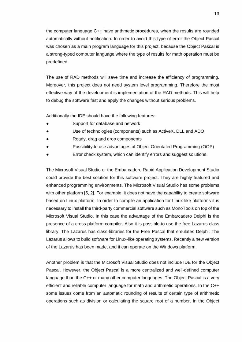
int i=5.7/4; //The result of this
//operation is 1, because
//it will be rounded
for(); //This a forever loop in C/C++.
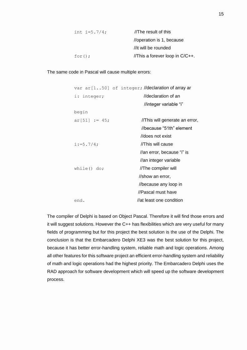
The same code in Pascal will cause multiple errors:
var ar[1..50] of integer; //declaration of array ar
i: integer; //declaration of an
//integer variable “i”
begin
ar[51] := 45; //This will generate an error,
//because “51th” element
//does not exist
i:=5.7/4; //This will cause
//an error, because “i” is
//an integer variable
while() do; //The compiler will
//show an error,
//because any loop in
//Pascal must have
end. //at least one condition
The compiler of Delphi is based on Object Pascal. Therefore it will find those errors and
it will suggest solutions. However the C++ has flexibilities which are very useful for many
fields of programming but for this project the best solution is the use of the Delphi. The
conclusion is that the Embarcadero Delphi XE3 was the best solution for this project,
because it has better error-handling system, reliable math and logic operations. Among
all other features for this software project an efficient error-handling system and reliability
of math and logic operations had the highest priority. The Embarcadero Delphi uses the
RAD approach for software development which will speed up the software development
process.

16
4 Results
The initial goal was to create a release version of the Educational Content Management
System for math-logical e-Learning. This goal was achieved on time and the software
has been deployed via a website. However, for this project the achievement in some
points is only a beginning of the next development cycle, because there is space for
further optimization of the code, improvement of the user-interface and development of
new features.
In the beginning the first plan and a UML diagram of this project were created. The algo-
rithmic-level optimization of this software project was carried out before the coding pro-
cess was started. The most time-consuming part of this project were the coding and
debugging procedures. Planning is one the most important part of any software project.
A clear, correct and reasonable plan can simplify and speed up the software project
development. It also can help to avoid re-building and fixing problems in a software pro-
ject later on.
The first rough plan was created at the beginning of this project. This plan showed dif-
ferent sides of this project and the connections between them. The diagram of the plan
is presented in Appendix 3. The design of the software included creation of a UML dia-
gram and a Graphical User Interface (GUI). A UML diagram visually describes an entire
software project, classes, methods, objects, data types, variables, constants without im-
plementation and coding.
The use of a UML diagram simplifies software development process and enables a pro-
grammer to find bugs or to optimize and improve a software project before implementa-
tion. Appendix 5 shows the UML diagram for this project. In this diagram the names of
modules, classes and methods are presented. In the design stage the optimization on
the algorithmic level for this software project was done. For example, each module of
this project had its own, separate connection to the database. Therefore, the same set
of the database connection methods (functions and procedures) were used many times
in the software. In order to optimize the software the database connection methods were
implemented once in the main module MainUnit.pas. This module is connected to the
other modules of this software. The database connection methods were declared as
public methods in the main module. Therefore they became accessible for all other mod-
ules (units). Consequently, more than two hundred lines of code were removed from the

17
code of this project. The optimization on the algorithmic level was useful for further de-
velopment of the project because it were simplified and reduced the program code.
After creation of a UML diagram for the project the next step was implementation of the
modules, classes and components. This step included fast prototyping of the methods,
coding and testing. In the testing phase of development a few issues of portability were
considered. For example, installing in a different version of a Linux-based OS had rela-
tively unexpected results. However, more feature development could eliminate those is-
sues.
The deployment of the software system was implemented via the Internet. For this pur-
pose a webpage was created. Embarcadero HTML5 Builder was used for design and
coding of the webpage. The HTML5 is the latest version of the markup language HTML.
It is the fifth revision of the HTML standard, which was created in 1990. It is simpler than
previous versions but at the same time it has more functionalities. All popular and modern
Internet browsers such as Google Chrome, Firefox and Internet Explorer are supporting
the HTML5. [10, 1]
The Embarcadero HTML5 Builder is a new member of the Embarcadero RAD Studio. It
uses the same RAD methods as Delphi in the RAD Studio. For example, hundreds of
ready drag-and-drop components are available in the IDE of the HTML5 Builder. It is
making prototyping process fast and easy. Additionally there is a possibility to type the
code and simultaneously to see the results without use of an Internet browser. [5, 2]
The Internet address of the webpage is www.alexeum.com where this project will be
available for download. The design of the webpage was based on the modern concepts
of web development. A modern webpage must be accessible via different devices such
as smartphones, tablets and netbooks. The main concept of Web Design is to highlight
the most important elements of a webpage concerning its content.
During this project I have learned more about software design, development and imple-
mentation of the RAD method and I got a rational and realistic picture of a full software
development cycle. Moreover, I learned more about web design, development and soft-
ware deployment and database design. Also I improved my writing skills.
18
4.1 Overview of the System
This software system is an application which can be installed and run on the Windows
platform. The interface of this program by default is full-screen, which helps a user to
focus on a given task. The design of this application’s Graphic User Interface (GUI) was
based on three following fundamental concepts:
I. Organize
II. Optimize
III. Communicate. [6, 1]
The first concept aims to provide the user with an interface with a clear and consistent
conceptual structure. All elements of an interface must have a clear order, well defined
positions and they should be visible. The second assumption states that the use of soft-
ware and hardware resources must be optimal. In this project the optimal use of the
resources can be achieved by keeping a balance between demands of the UI and avail-
ability of resources. For example, a three-dimensional user-interface might be useful but
it will require more hardware resources than an average computer has. On the other
hand the use of a command-line type of interface might save hardware resources but it
is not convenient and it is too “poor” for a modern computer. Therefore the best solution
for this project is to create a regular and two dimensional modern graphic user interface.
The last assumption says that the UI must keep legibility, readability, typography, sym-
bolism, multiple views and color or texture in balance in order to communicate success-
fully. An example of a modern, balanced interface is the Windows Metropolis UI. How-
ever, it has functionality issues. [6, 1]
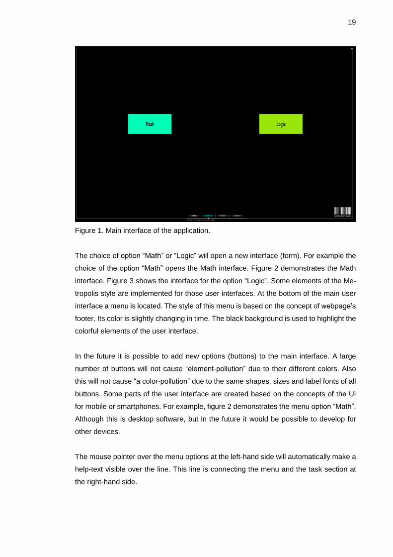
Figure 1 illustrates the user interface of this software project.
19
Figure 1. Main interface of the application.
The choice of option “Math” or “Logic” will open a new interface (form). For example the
choice of the option “Math” opens the Math interface. Figure 2 demonstrates the Math
interface. Figure 3 shows the interface for the option “Logic”. Some elements of the Me-
tropolis style are implemented for those user interfaces. At the bottom of the main user
interface a menu is located. The style of this menu is based on the concept of webpage’s
footer. Its color is slightly changing in time. The black background is used to highlight the
colorful elements of the user interface.
In the future it is possible to add new options (buttons) to the main interface. A large
number of buttons will not cause “element-pollution” due to their different colors. Also
this will not cause “a color-pollution” due to the same shapes, sizes and label fonts of all
buttons. Some parts of the user interface are created based on the concepts of the UI
for mobile or smartphones. For example, figure 2 demonstrates the menu option “Math”.
Although this is desktop software, but in the future it would be possible to develop for
other devices.
The mouse pointer over the menu options at the left-hand side will automatically make a
help-text visible over the line. This line is connecting the menu and the task section at
the right-hand side.
20
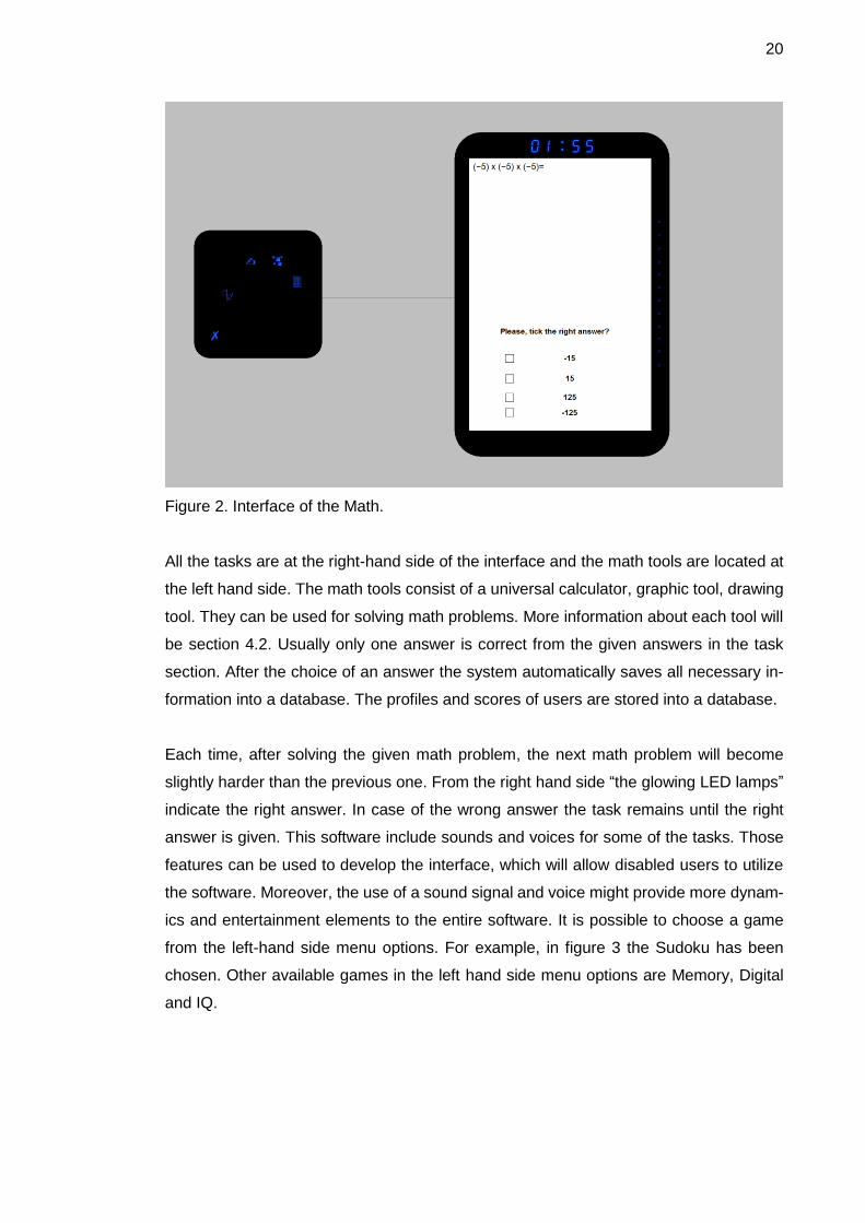
Figure 2. Interface of the Math.
All the tasks are at the right-hand side of the interface and the math tools are located at
the left hand side. The math tools consist of a universal calculator, graphic tool, drawing
tool. They can be used for solving math problems. More information about each tool will
be section 4.2. Usually only one answer is correct from the given answers in the task
section. After the choice of an answer the system automatically saves all necessary in-
formation into a database. The profiles and scores of users are stored into a database.
Each time, after solving the given math problem, the next math problem will become
slightly harder than the previous one. From the right hand side “the glowing LED lamps”
indicate the right answer. In case of the wrong answer the task remains until the right
answer is given. This software include sounds and voices for some of the tasks. Those
features can be used to develop the interface, which will allow disabled users to utilize
the software. Moreover, the use of a sound signal and voice might provide more dynam-
ics and entertainment elements to the entire software. It is possible to choose a game
from the left-hand side menu options. For example, in figure 3 the Sudoku has been
chosen. Other available games in the left hand side menu options are Memory, Digital
and IQ.

21
Figure 3. Logic games. Sudoku.
Figure 3 shows the case when a user clicks button “Logic” in the main interface and then
chooses the “Sudoku” option from the left-hand side menu. The timer automatically sets
for 10 minutes. During this time the user should fill all empty cells. After this software will
automatically check the Sudoku. If it is correct, then a new Sudoku will appear. Except
for the main interface where the buttons “Math” and “Logic” are located all other inter-
faces (forms) have three buttons in the right-bottom corner. Table 2 shows the function-
alities of those buttons.
22
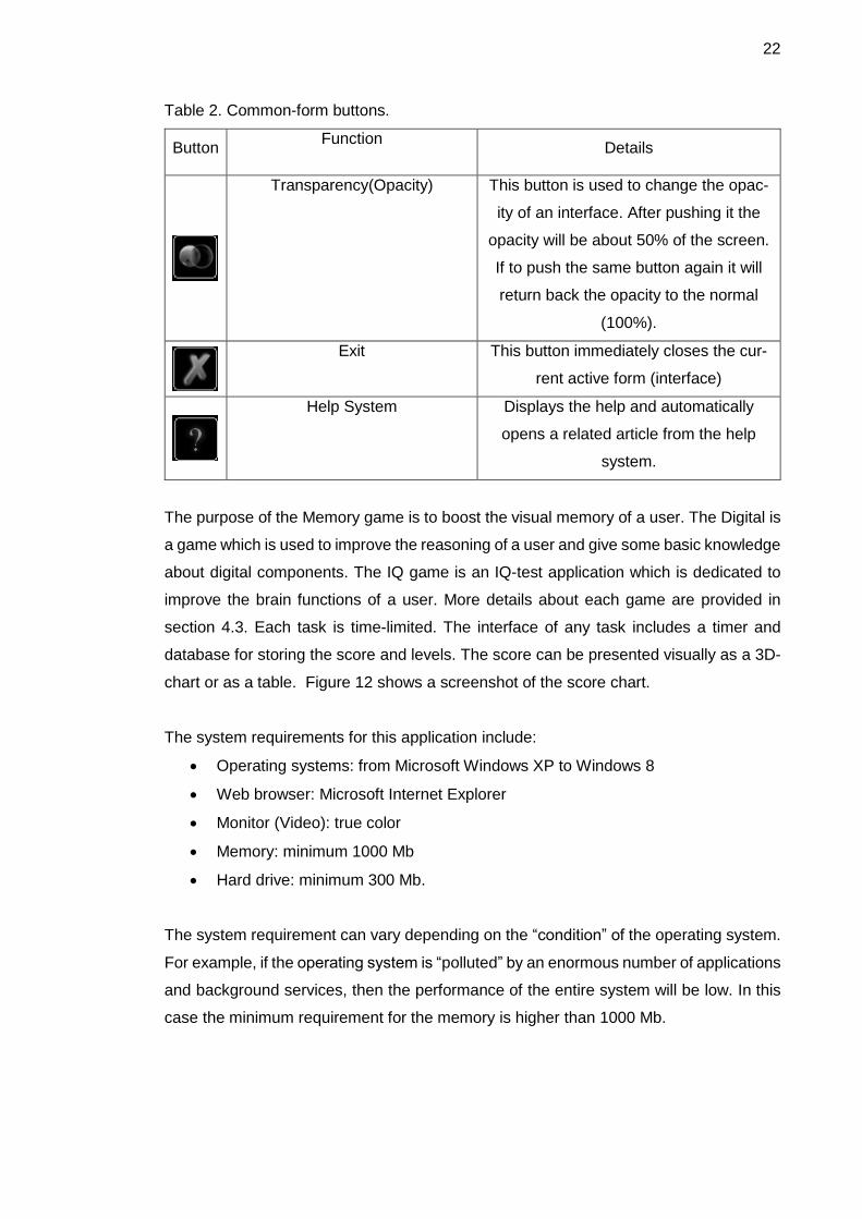
Table 2. Common-form buttons.
Button Function
Details
Transparency(Opacity) This button is used to change the opac-
ity of an interface. After pushing it the
opacity will be about 50% of the screen.
If to push the same button again it will
return back the opacity to the normal
(100%).
Exit This button immediately closes the cur-
rent active form (interface)
Help System Displays the help and automatically
opens a related article from the help
system.
The purpose of the Memory game is to boost the visual memory of a user. The Digital is
a game which is used to improve the reasoning of a user and give some basic knowledge
about digital components. The IQ game is an IQ-test application which is dedicated to
improve the brain functions of a user. More details about each game are provided in
section 4.3. Each task is time-limited. The interface of any task includes a timer and
database for storing the score and levels. The score can be presented visually as a 3D-
chart or as a table. Figure 12 shows a screenshot of the score chart.
The system requirements for this application include:
Operating systems: from Microsoft Windows XP to Windows 8
Web browser: Microsoft Internet Explorer
Monitor (Video): true color
Memory: minimum 1000 Mb
Hard drive: minimum 300 Mb.
The system requirement can vary depending on the “condition” of the operating system.
For example, if the operating system is “polluted” by an enormous number of applications
and background services, then the performance of the entire system will be low. In this
case the minimum requirement for the memory is higher than 1000 Mb.
23
This software project utilized the ActiveX-components from the Microsoft Internet Ex-
plorer (IE). Usually IE is embedded into the operating system Windows. Therefore there
should not appear any problems concerning this requirement. Figure 14 shows the da-
tabase of the Math game. The Microsoft Access is used to open the DB. There is a field
“Math Word Problems” where are located math tasks. The field “Variants” contains a list
of all answers. In this list only one answer is correct. The letter which indicates the correct
answer is located in the field “Answers”.
This DB can be edited by teachers. The format of DB file is in the MDB. Therefore for
editing the content of this database it is possible to use the MS Access. There are other
programs which can be used for editing the DB, for example, the PremiumSoft Navicat.
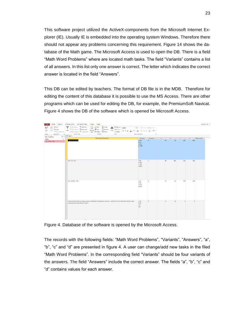
Figure 4 shows the DB of the software which is opened be Microsoft Access.
Figure 4. Database of the software is opened by the Microsoft Access.
The records with the following fields: “Math Word Problems”, “Variants”, “Answers”, “a”,
“b”, “c” and “d” are presented in figure 4. A user can change/add new tasks in the filed
“Math Word Problems”. In the corresponding field “Variants” should be four variants of
the answers. The field “Answers” include the correct answer. The fields “a”, “b”, “c” and
“d” contains values for each answer.
24
4.2 Math Tools
The menu Math tools is in the left hand side of the interface of Math. As mentioned in
section 4.1 it includes the universal calculator, graphic tool and drawing tools. The math
tools can be used to solve math problems which appear in the right-hand side of the
interface of “Math”.
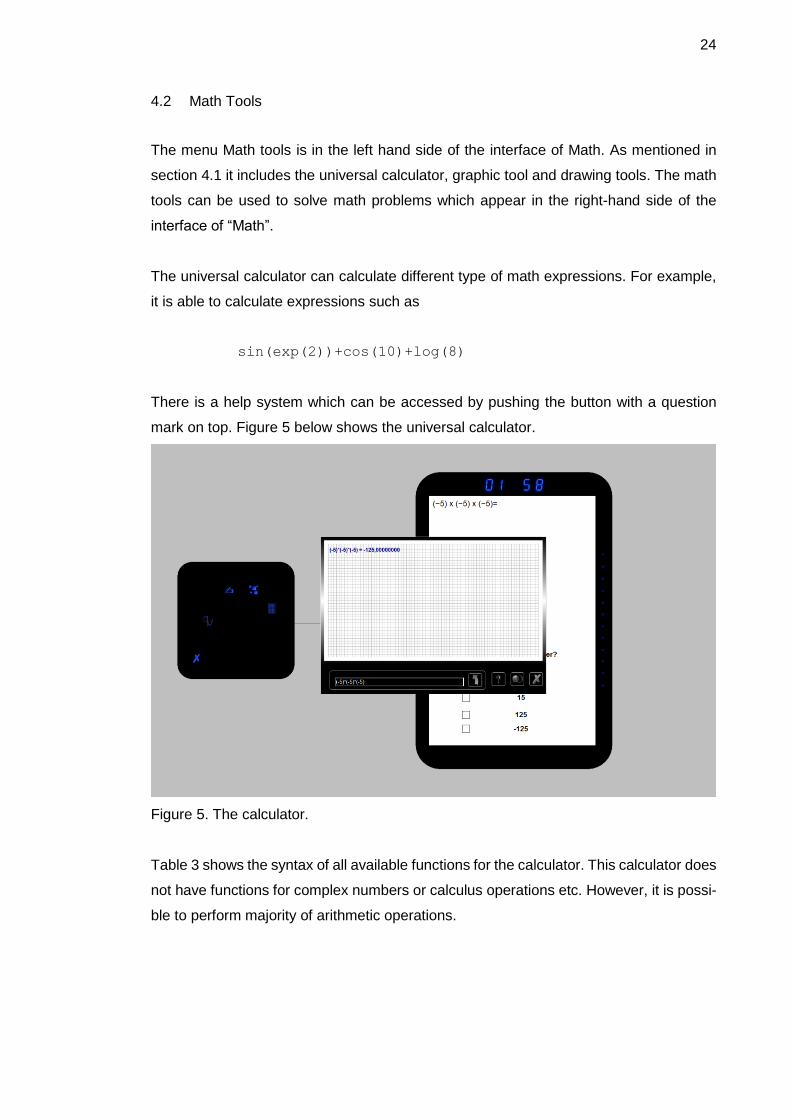
The universal calculator can calculate different type of math expressions. For example,
it is able to calculate expressions such as
sin(exp(2))+cos(10)+log(8)
There is a help system which can be accessed by pushing the button with a question
mark on top. Figure 5 below shows the universal calculator.
Figure 5. The calculator.
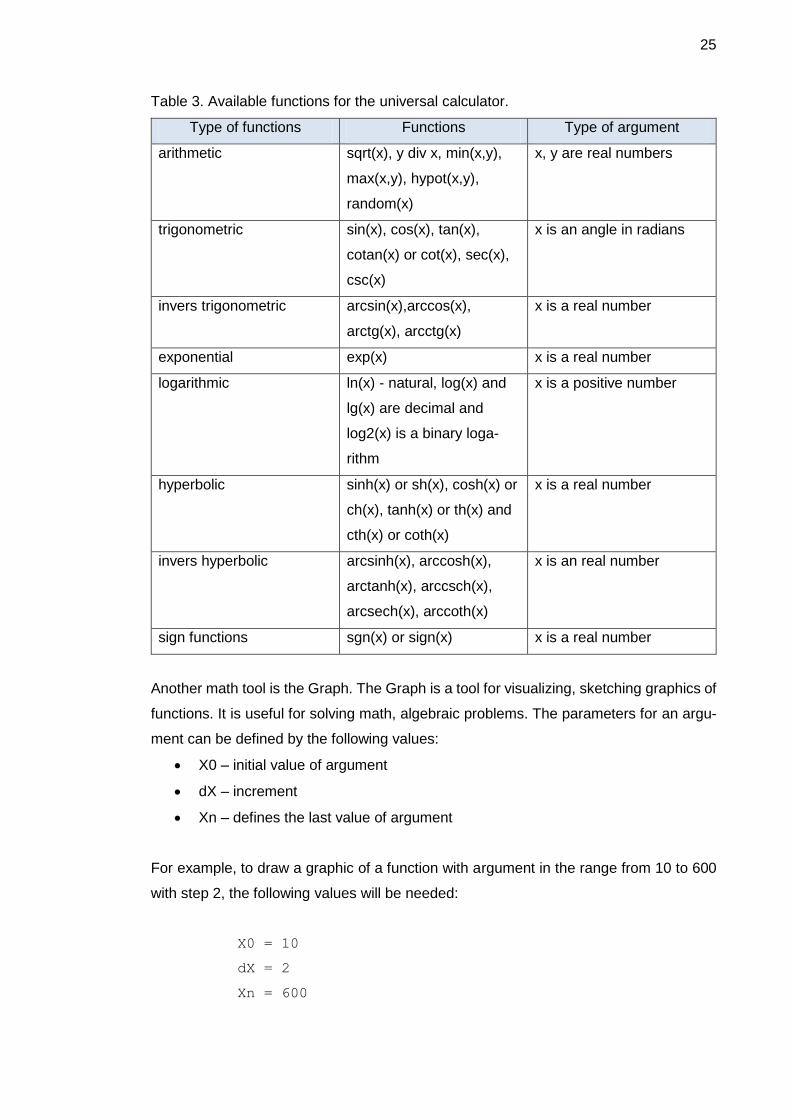
Table 3 shows the syntax of all available functions for the calculator. This calculator does
not have functions for complex numbers or calculus operations etc. However, it is possi-
ble to perform majority of arithmetic operations.
25
Table 3. Available functions for the universal calculator.
Type of functions Functions Type of argument
arithmetic sqrt(x), y div x, min(x,y),
max(x,y), hypot(x,y),
random(x)
x, y are real numbers
trigonometric sin(x), cos(x), tan(x),
cotan(x) or cot(x), sec(x),
csc(x)
x is an angle in radians
invers trigonometric arcsin(x),arccos(x),
arctg(x), arcctg(x)
x is a real number
exponential exp(x) x is a real number
logarithmic ln(x) - natural, log(x) and
lg(x) are decimal and
log2(x) is a binary loga-
rithm
x is a positive number
hyperbolic sinh(x) or sh(x), cosh(x) or
ch(x), tanh(x) or th(x) and
cth(x) or coth(x)
x is a real number
invers hyperbolic arcsinh(x), arccosh(x),
arctanh(x), arccsch(x),
arcsech(x), arccoth(x)
x is an real number
sign functions sgn(x) or sign(x) x is a real number
Another math tool is the Graph. The Graph is a tool for visualizing, sketching graphics of
functions. It is useful for solving math, algebraic problems. The parameters for an argu-
ment can be defined by the following values:
X0 – initial value of argument
dX – increment
Xn – defines the last value of argument
For example, to draw a graphic of a function with argument in the range from 10 to 600
with step 2, the following values will be needed:
X0 = 10
dX = 2
Xn = 600

26
In this case the new values for X till Xn will be defined as:
X = X + dX
The same operation in the MATLAB will require the following sequence of commands:
x = 10:2:600;
y = some_function(x);
plot(x,y);
The same module (unit) which has been used for the universal calculator is used for the
Graph. Therefore Table 3 presents all available functions for universal calculator and
also shows all available functions for the Graph, except for the double-argument func-
tions. In order to use the Graph to draw a graphic of a function it is necessary to use the
letter “x” as an argument. The function should be from the table of available functions.
Otherwise the Graphic will display an error message. There is a possibility for a compo-
sition of functions. For example, the composition of functions can be defined as the fol-
lowing expression:
sin(log(x)*cos(x/23))
Usually in the Object Pascal recursive functions are used for this type of calculations.
The recursive functions are utilizing the stack memory. The stack memory of a computers
has a high speed compared with other types of memory. At the same time the size of the
stack memory is relatively small. Therefore the number of recursion steps are limited by
the size of the stack memory.
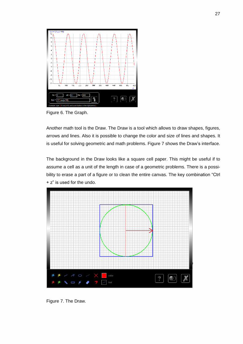
Figure 6 shows the Graph. In this screen-shot the Graph is used to sketch the function:
f(x) = 12*cos(x/18)
27
Figure 6. The Graph.
Another math tool is the Draw. The Draw is a tool which allows to draw shapes, figures,
arrows and lines. Also it is possible to change the color and size of lines and shapes. It
is useful for solving geometric and math problems. Figure 7 shows the Draw’s interface.
The background in the Draw looks like a square cell paper. This might be useful if to
assume a cell as a unit of the length in case of a geometric problems. There is a possi-
bility to erase a part of a figure or to clean the entire canvas. The key combination “Ctrl
+ z” is used for the undo.
Figure 7. The Draw.

28
The Block is a tool which helps to solve math or logic text problems. Figure 8 represents
the Block. The position, size and color of any block can be changed. Also it is possible
to add a new block, to delete a block or to type a symbol on top of a block. Moreover the
Block can be used for drawing a chart. All those features will allow a user to create a
visual model for a math or logic text problem. This software is very useful for text prob-
lems which contain comparison tasks.
Figure 8. The Block.
4.3 Description of the Games
Sudoku it is one of the most popular puzzle-games worldwide. Figure 3 in section 4.1
illustrate the screen-shot for Sudoku. Sudoku is played over a 9x9 grid, divided into 3x3
subgrids called "regions" or blocks. Figure 9 shows the subgrids of a Sudoku. The rules
for Sudoku are easy: a digit can appear only once on each row, column and region
(sugrids).

29
Figure 9. The subgrids of a Sudoku.
The purpose of the Memory game is to improve a user’s memory by making him or her
to memorize different figures and shapes. During the game the figures (shapes) will ap-
pear and disappear from the screen. The user’s task is to reproduce them by clicking on
the corresponding cells. Pushing the correct cell is more important. Pushing the wrong
cell leads to starting the game again. The order of pushing cells does not matter. Figure
10 is a screenshot of the Memory game.
Figure 10. Screenshot of the Memory game.
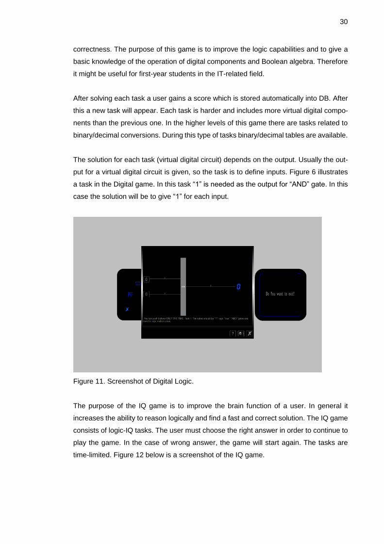
The screenshot of the Digital game is presented in figure 11. The Digital game is based
on the digital logic and discrete math. There are the virtual logic components such as
AND, OR, XOR. The order of clicking on the correct button is important as well as the
30
correctness. The purpose of this game is to improve the logic capabilities and to give a
basic knowledge of the operation of digital components and Boolean algebra. Therefore
it might be useful for first-year students in the IT-related field.
After solving each task a user gains a score which is stored automatically into DB. After
this a new task will appear. Each task is harder and includes more virtual digital compo-
nents than the previous one. In the higher levels of this game there are tasks related to
binary/decimal conversions. During this type of tasks binary/decimal tables are available.
The solution for each task (virtual digital circuit) depends on the output. Usually the out-
put for a virtual digital circuit is given, so the task is to define inputs. Figure 6 illustrates
a task in the Digital game. In this task “1” is needed as the output for “AND” gate. In this
case the solution will be to give “1” for each input.
Figure 11. Screenshot of Digital Logic.
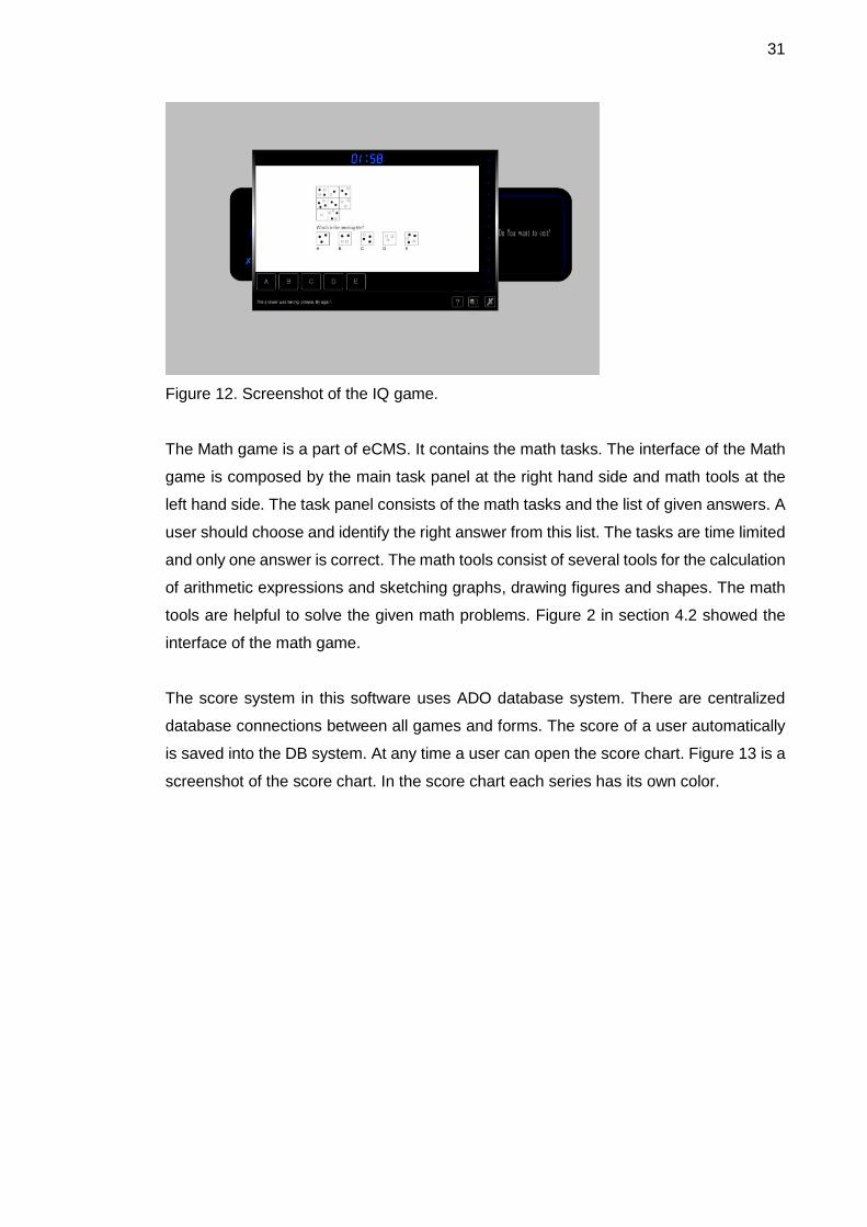
The purpose of the IQ game is to improve the brain function of a user. In general it
increases the ability to reason logically and find a fast and correct solution. The IQ game
consists of logic-IQ tasks. The user must choose the right answer in order to continue to
play the game. In the case of wrong answer, the game will start again. The tasks are
time-limited. Figure 12 below is a screenshot of the IQ game.
31
Figure 12. Screenshot of the IQ game.
The Math game is a part of eCMS. It contains the math tasks. The interface of the Math
game is composed by the main task panel at the right hand side and math tools at the
left hand side. The task panel consists of the math tasks and the list of given answers. A
user should choose and identify the right answer from this list. The tasks are time limited
and only one answer is correct. The math tools consist of several tools for the calculation
of arithmetic expressions and sketching graphs, drawing figures and shapes. The math
tools are helpful to solve the given math problems. Figure 2 in section 4.2 showed the
interface of the math game.
The score system in this software uses ADO database system. There are centralized
database connections between all games and forms. The score of a user automatically
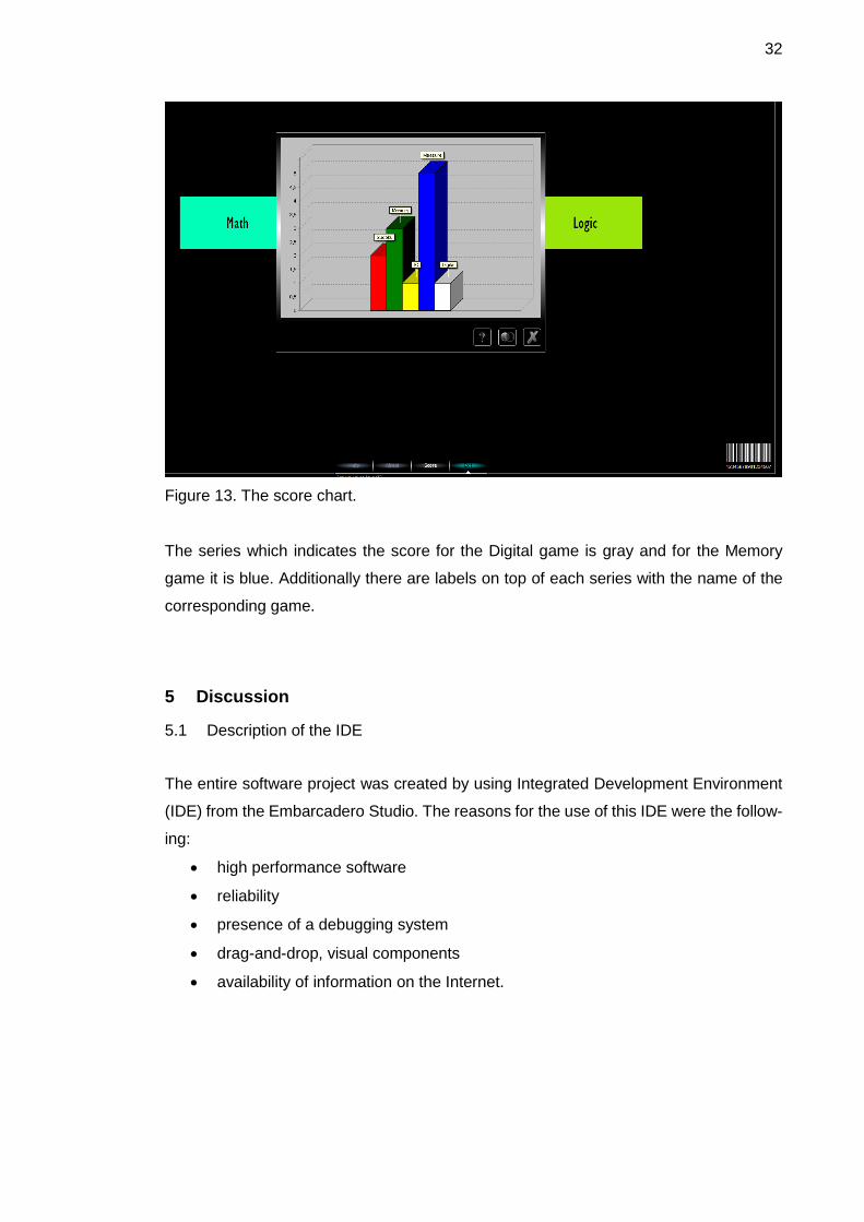
is saved into the DB system. At any time a user can open the score chart. Figure 13 is a
screenshot of the score chart. In the score chart each series has its own color.
32
Figure 13. The score chart.
The series which indicates the score for the Digital game is gray and for the Memory
game it is blue. Additionally there are labels on top of each series with the name of the
corresponding game.
5 Discussion
5.1 Description of the IDE
The entire software project was created by using Integrated Development Environment
(IDE) from the Embarcadero Studio. The reasons for the use of this IDE were the follow-
ing:
high performance software
reliability
presence of a debugging system
drag-and-drop, visual components
availability of information on the Internet.
33
The RAD studio allows to build rapidly and efficiently high performance software products
for Windows and other platforms. One important part of any software project is to make
a correct implementation plan. The plan for this project consisted of the following steps:
to install programming tools
to check functionality of the IDE and components
to start coding the main unit of the project
to compile and test the code.
The first step included installations of the following software:
The main IDE Embarcadero RAD Studio XE3 with Delphi
Additional plugins and components for the RAD Studio
Software tools for image processing
Installer/uninstaller maker
Microsoft Access 2003.
The second important step was to check functionality of the IDE, because any problem
in the IDE's functionality might cause an unexpected result in the later stages of a soft-
ware development process. In the case of a functionality problem in the IDE's it was
necessary to change the IDE and start the project from the beginning. This will be waste
of time and efforts.
The third and the fourth steps were possible to implement only if the IDE and all addi-
tional components were working properly. Testing is an important and time consuming
part of any software development process. The RAD software development cycle shortly
can be described as following: testing -> debugging -> implementing -> back to testing.
Therefore the RAD method is periodical software development process. In this project
the RAD method was used.
In addition in this project DLL modules and Microsoft ADO system were widely used. The
use of a DLL module is beneficial for this project. The main advantage is an optimal
utilization of memory by reusing the same copy of a method (function or procedure) for
different processes in the system. This eventually increases performance of an entire
application [1, 4]. Also the simultaneous access and use of a DLL file by different pro-
cesses is possible. DLL –files have relatively small size. Therefore it easy and fast to
transfer a DLL-file via the Internet. This simplifies the software updating and upgrading
processes.

34
Furthermore an important advantage of the DLL technology is high security. For exam-
ple, it is possible to store any kind of data, codes inside of a DLL file. The DLL files are
coded and encrypted in the same way as EXE files. The “funcom.dll” is a DLL module
which is created in this project to re-use the methods and to store the data. More infor-
mation about this file (module) is in the next section. In this project the important reasons
for implementation of DLL technology were to increase program performance and to im-
prove security of software. The security-sensitive data of this project were stored into
DLL files. Additionally the often-used functions were dispatched into DLL files. This will
save efficiently the use of operational memory in runtime.
Other technology which was used in this project was the Microsoft ADO system. The use
of ADO technology allows to establish a connection, to access and to manipulate a da-
tabase through a program. The important benefits of an ADO system are easy to pro-
gram and it has high performance. Moreover, it requires only the connection and
knowledge of SQL for programmers is not mandatory [5, 60].
A secondary advantage is a possibility to control the cursor’s position. This includes com-
plex cursor types such as batch and server and client-side cursors [2, 4]. Other important
benefits of the Microsoft ADO system are the ability to return multiple result sets from a
single query as well as synchronous, asynchronous, or event-driven query execution.
Reusability, property-changeable objects, advanced record-set cache management and
flexibility, which work with the existing database technologies, and all OLE DB providers
are useful properties of the Microsoft ADO system. [4, 121].
5.2 The Coding Requirements
This section discusses important aspects of the program code. Before description of the
coding it is necessary to emphasize the main requirements for the software project. The
requirements depend on the coding as well as on the programing environment. Main
requirements are:
portability
reusability
user-friendly interface.
35
Portability was an important requirement for this project but it was part of the further
development plan. In general the Embarcadero RAD Studio is able to compile and to
make an EXE-file for the Windows OS platform. Also it can generate an executable file
for the Mac OS. Those features partly were solved the portability issues. Other important
requirement was reusability which was achieved by adding functionalities such as Data-
base Control through interface. So, from the beginning of the coding it was taken into
account. In the context of this project reusability means:
I. to create reusable classes and components for the further development
II. to build a software which can be re-used for different purposes
For instance, in this project the software can be changed manually. In order to have an
educational software for another subject than Math or Logic it is enough to change only
the content of corresponding database. User-friendly interface must be easy and under-
standable for anybody. A modern user-friendly interface should have modern features
and be adequate to the recent trends in this field.
A coding process included the following steps:
to classify units based on functionality
to code prototypes
to implement methods
to debug
Classification of units was the first step for the coding process. For example, the unit for
database functions was defined separately from the unit, which contains constants or
functions for the user interface. The name of a unit was very important in the coding. For
instance, the unit which includes the math functions was named correspondingly. In this
project each unit has defined a name such as MathUnit or LogicUnit. They have made it
easy to test and debug the software.
5.3 The Coding
Coding was the next step after design of a software project. The coding was based on
the UML diagram of this software project. The name of classes, methods, fields and
connections between them are presented in the UML diagram. In this step it was needed
36
to define data types, variables and to create prototype of methods and classes according
to the UML diagram Appendix 5.
The next step was an implementation of the methods (functions and procedures). With-
out implementation, the methods were “empty” procedures and functions. Therefore the
corresponding classes were abstract. The implementation was included defining behav-
ior of the classes and values for the fields. For example, if there was a class “Math” and
it had method “Sum(a, b : real):real” then its implementation in Object Pascal had to be
like in listing 1.
function Math.Sum(a,b :real):real;
begin
result:= a + b;
end;
Listing 1. An example of method implementation.
The debugging process was the most time-consuming process. Therefore it was very
important to avoid “bugs” during the coding. This software was a standalone application
which means that it has well defined location in the hard disc. There was also an Internet
connection which provides data-exchange with the main Internet server.
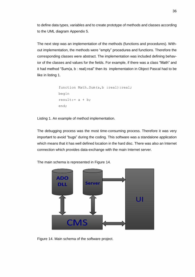
The main schema is represented in Figure 14.
Figure 14. Main schema of the software project.
37
Figure 14 shows connections between different parts of this software project. The server
part is connected via Internet to the other parts of the software. The UI has a connection
to the CMS and a connection to server. Also it is implicitly connected to the all other parts
of the system through CMS.
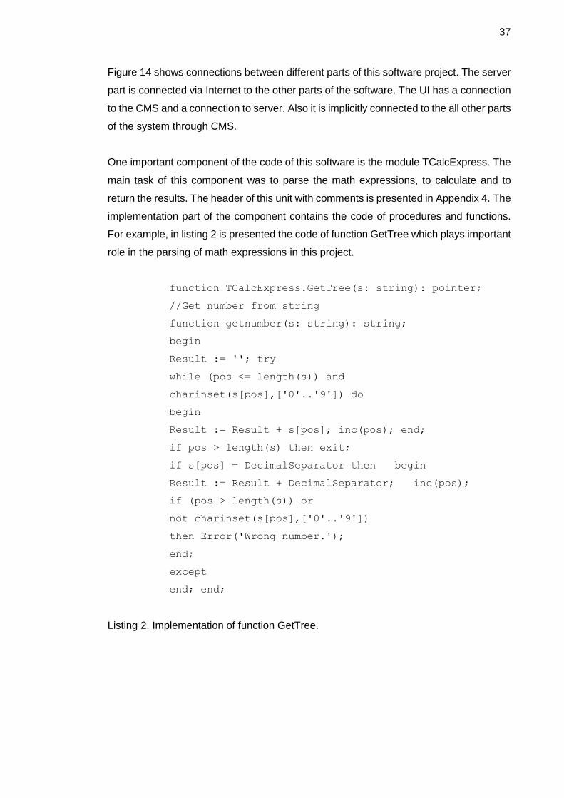
One important component of the code of this software is the module TCalcExpress. The
main task of this component was to parse the math expressions, to calculate and to
return the results. The header of this unit with comments is presented in Appendix 4. The
implementation part of the component contains the code of procedures and functions.
For example, in listing 2 is presented the code of function GetTree which plays important
role in the parsing of math expressions in this project.
function TCalcExpress.GetTree(s: string): pointer;
//Get number from string
function getnumber(s: string): string;
begin
Result := ''; try
while (pos <= length(s)) and
charinset(s[pos],['0'..'9']) do
begin
Result := Result + s[pos]; inc(pos); end;
if pos > length(s) then exit;
if s[pos] = DecimalSeparator then begin
Result := Result + DecimalSeparator; inc(pos);
if (pos > length(s)) or
not charinset(s[pos],['0'..'9'])
then Error('Wrong number.');
end;
except
end; end;
Listing 2. Implementation of function GetTree.
38
A full listing of this code is available in Appendix 4. Also the comments and some expla-
nations for this code are presented. Other important component/unit was the QuizeSys-
tem.pas. The full listing of this unit is available in the appendix 2. In this section are
explanation for some of important procedures and functions from the QuizeSystem.pas.
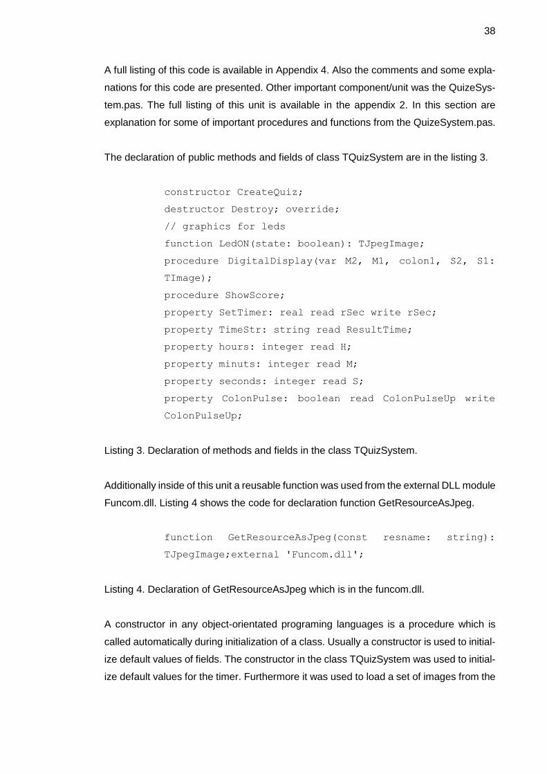
The declaration of public methods and fields of class TQuizSystem are in the listing 3.
constructor CreateQuiz;
destructor Destroy; override;
// graphics for leds
function LedON(state: boolean): TJpegImage;
procedure DigitalDisplay(var M2, M1, colon1, S2, S1:
TImage);
procedure ShowScore;
property SetTimer: real read rSec write rSec;
property TimeStr: string read ResultTime;
property hours: integer read H;
property minuts: integer read M;
property seconds: integer read S;
property ColonPulse: boolean read ColonPulseUp write
ColonPulseUp;
Listing 3. Declaration of methods and fields in the class TQuizSystem.
Additionally inside of this unit a reusable function was used from the external DLL module
Funcom.dll. Listing 4 shows the code for declaration function GetResourceAsJpeg.
function GetResourceAsJpeg(const resname: string):
TJpegImage;external 'Funcom.dll';
Listing 4. Declaration of GetResourceAsJpeg which is in the funcom.dll.
A constructor in any object-orientated programing languages is a procedure which is
called automatically during initialization of a class. Usually a constructor is used to initial-
ize default values of fields. The constructor in the class TQuizSystem was used to initial-
ize default values for the timer. Furthermore it was used to load a set of images from the
39
resource file and from the funcom.dll. In Delphi other automatic procedure is destructor
as well as in other OOP computer languages. Often a destructor is used to return the
occupied memory back to the operating system. Therefore it is called automatically at
the end of an application. In the unit TQuizSystem the destructor was cleaning memory
space which was used by all image objects. The image objects were the fields of the
class TQuizSystem.
The procedure DigitalDisplay was playing very important role in this project. It was re-
sponsible for the timer for all tasks in the system. Any task in the system is time limited.
Therefore an adjustable and visible timer was needed. The procedure LedON(state:
Boolean) was used to turn on or off the “LED” lamps in the score bar of the games. The
parameter “state” was a Boolean variable. It could have the values false or true corre-
sponding to a lamp’s off or on state.
In Delphi the properties are the fields of a class. For example, in the class TQuizSystem
the property SetTimer was used to set current state of the timer. It was possible to write
and to read the value of this property. Declaration of SetTimer in the class TQuizSystem
was
property SetTimer: real read rSec write rSec;
This declaration defines connection between SetTimer and private variable rSec.
The variable rSec was private in the class TQuizSystem, which means that it was visible
only inside of the class.
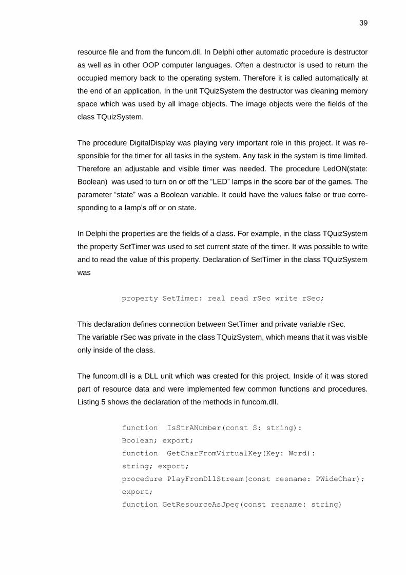
The funcom.dll is a DLL unit which was created for this project. Inside of it was stored
part of resource data and were implemented few common functions and procedures.
Listing 5 shows the declaration of the methods in funcom.dll.
function IsStrANumber(const S: string):
Boolean; export;
function GetCharFromVirtualKey(Key: Word):
string; export;
procedure PlayFromDllStream(const resname: PWideChar);
export;
function GetResourceAsJpeg(const resname: string)
40
:TJPEGImage; export;
procedure Delay(Milliseconds: Integer);
export;
function Find_Max(Arr: array of real): byte;
export;
function Find_Min(Arr: array of real): byte;
export;
Listing 5. Declaration of the methods inside of funcom.dll.
The function IsStrANumber defines either the parameter S was a string variable or not.
The GetResourceAsJpeg was used to fetch images from the funcom.DLL as JPEG-for-
mat objects. It was widely used in this project. The GetCharFromVirtualKey was a func-
tion which returns a character correspondingly to a pushed key on the keyboard. The
PlayFromDllStream was a procedure in funcom.dll which was dedicated to play WAVE-
files from funcom.dll. It was using the Windows API procedure sndPlaySound. The pro-
cedure Delay was used to generate pause during the runtime. The length of a pause was
given in milliseconds. The functions Find_Max and Find_Min were used to find corre-
spondingly the largest and smallest element of a given array.
6 Conclusions
The goal of project was to develop the math-logic educational CMS which would allow
the user to change the content of the software. It contains certain games for educational-
entertainment purposes. The main result of the software project is a software system
and a content management system for improving math-logic skills.
The strength of the project was a fully functional and user-friendly interface which corre-
sponds to the objectives set in the beginning of the project and it was successfully ac-
complished in the given time-frame. The goal of this project was successfully met as
described in the introduction. The important achievement of this final project was gaining
knowledge and skills about the full cycle of software development from design to the final
testing. During the work on the project my programming, coding skills as well as produc-
tivity, project and time management skills were improved.
41
The limitations appeared when the software was tested on the Linux platform, but this
problem will be solved in the future development of the software. The project’s results
could be useful for secondary schools. The age of users could vary from 12 to 16 years.
Some of logic games could be useful for IT students.
The content of the math games can be changed by teachers in a very simple manner.
The Microsoft Access can be used to edit the databases of this software, and therefore
teachers could define the tasks depending on the required level or demands of the school
program. In the same way a user can to edit other databases of this software, for exam-
ple the database of logic games or the Sudoku.
42
References
1 Microsoft Corporation. What is DLL? [Online]. USA, Microsoft; December
2007.
URL: http://support.microsoft.com/kb/815065
Accessed 26 January 2012.
2 Microsoft Corporation. Data Access Using ActiveX Data Objects (ADO)
[Online]. USA, Microsoft; December 2010.
URL: http://msdn.microsoft.com/en-us/library/aa266541(v=vs.60).aspx
Accessed 26 January 2012.
3 Microsoft Corporation. .NET Framework Conceptual Overview [online]. USA,
Microsoft; September 2010.
URL: http://msdn.microsoft.com/en-us/library/zw4w595w.aspx
Accessed 26 January 2012.
4 Box Don and Sells Chris. Essential .NET: The Common Language Runtime.
Canada, Pearson Education Inc; 2004.
5 Martin James. Rapid Application Development. UK, Macmillan Coll Div;
1991.
6 Martin Suzanne. Effective Visual Communication for Graphical User Interfaces
[online].USA, Colors-UI; April 2013.
URL: http://web.cs.wpi.edu/~matt/courses/cs563/talks/smartin/int_design.html
Accessed 16 April 2013.
7 Joomla Website [online]. USA, Joomla Foundation; August 17.
URL: http://www.joomla.org/
Accessed 19 September 2013
8 About.com Website [online]. USA, David Bolton; September 23.
URL: http://cplus.about.com/od/glossar1/Glossary_of_Programming_Terms.htm
Accessed 23 September 2013

43
9 Harsha S. Hadiga. Writing endian-independent code in C [online]. IBM Software Group;
April 2007.
URL: http://www.ibm.com/developerworks/aix/library/au-endianc/index.html?ca=drs-
Accessed 23 September 2013
10 World Wide Web Consortium. HTML5 [online].
URL: http://www.w3.org/TR/html5/
Accessed 23 September 2013
Appendix 1
1 (3)
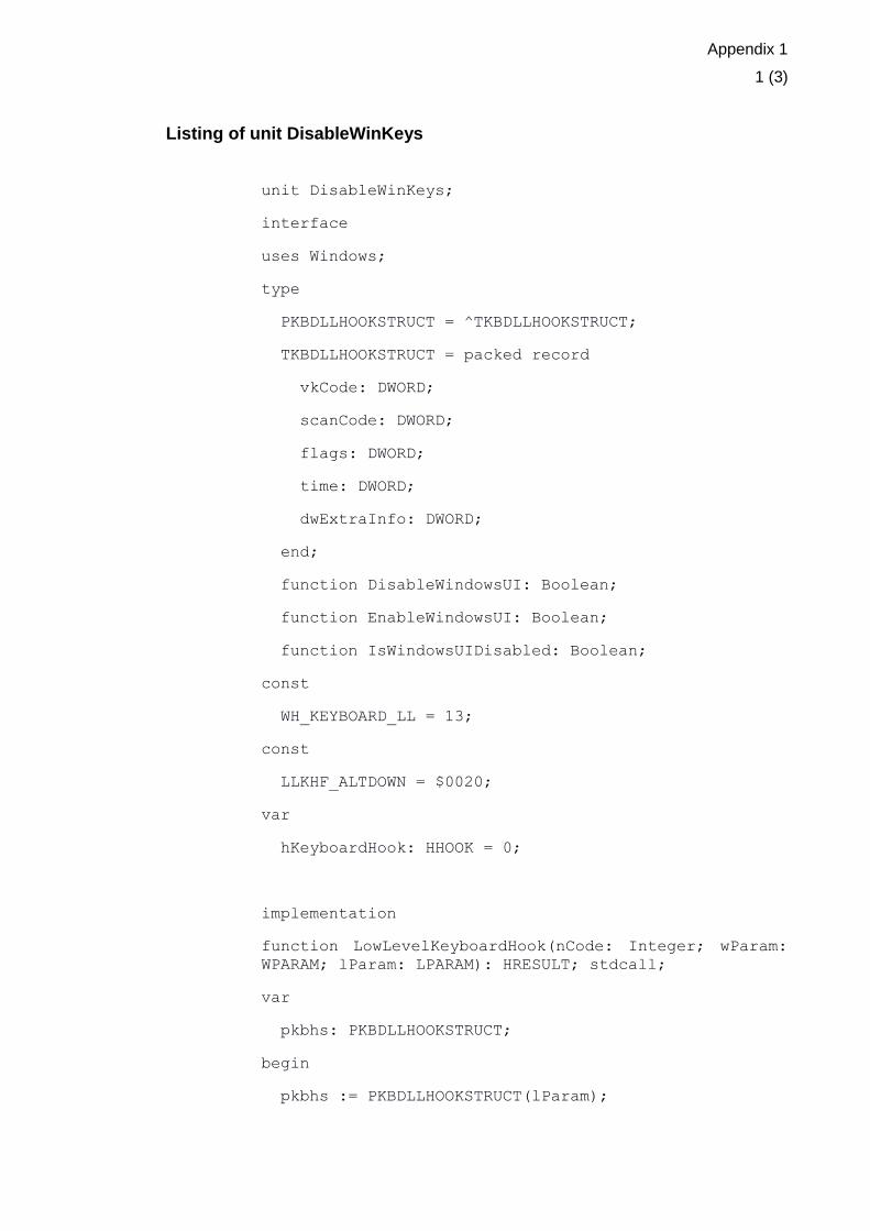
Listing of unit DisableWinKeys
unit DisableWinKeys;
interface
uses Windows;
type
PKBDLLHOOKSTRUCT = ^TKBDLLHOOKSTRUCT;
TKBDLLHOOKSTRUCT = packed record
vkCode: DWORD;
scanCode: DWORD;
flags: DWORD;
time: DWORD;
dwExtraInfo: DWORD;
end;
function DisableWindowsUI: Boolean;
function EnableWindowsUI: Boolean;
function IsWindowsUIDisabled: Boolean;
const
WH_KEYBOARD_LL = 13;
const
LLKHF_ALTDOWN = $0020;
var
hKeyboardHook: HHOOK = 0;
implementation
function LowLevelKeyboardHook(nCode: Integer; wParam:
WPARAM; lParam: LPARAM): HRESULT; stdcall;
var
pkbhs: PKBDLLHOOKSTRUCT;
begin
pkbhs := PKBDLLHOOKSTRUCT(lParam);

Appendix 1
2 (3)
if nCode = HC_ACTION then
begin
// Disable CTRL+ESC
if(pkbhs^.vkCode=VK_ESCAPE)and
WordBool(GetAsyncKeyState(VK_CONTROL) and $8000) then
begin
Result := 1;
Exit;
end;
// Disable ALT+TAB
if (pkbhs^.vkCode = VK_TAB) and
LongBool(pkbhs^.flags and LLKHF_ALTDOWN) then
begin
Result := 1;
Exit;
end;
// Disable ALT+ESC
if (pkbhs^.vkCode = VK_ESCAPE) and
LongBool(pkbhs^.flags and LLKHF_ALTDOWN) then
begin
Result := 1;
Exit;
end;
// Disable ALT+F4
if (pkbhs^.vkCode = VK_F4) and
LongBool(pkbhs^.flags and LLKHF_ALTDOWN) then
begin
Result := 1;
Exit;
end;
end;

Appendix 1
3 (3)
Result := CallNextHookEx(hKeyboardHook, nCode,
wParam, lParam);
end;
function DisableWindowsUI: Boolean;
begin
if hKeyboardHook = 0 then
hKeyboardHook := SetWindowsHookEx(WH_KEYBOARD_LL,
@LowLevelKeyboardHook, HInstance, 0);
Result := (hKeyboardHook <> 0)
end;
function EnableWindowsUI: Boolean;
begin
Result := False;
if (hKeyboardHook <> 0) and
UnhookWindowsHookEx(hKeyboardHook) then
begin
hKeyboardHook := 0;
Result := True;
end;
end;
function IsWindowsUIDisabled: Boolean;
begin
Result := (hKeyboardHook <> 0)
end;
end.
Appendix 2
1 (5)
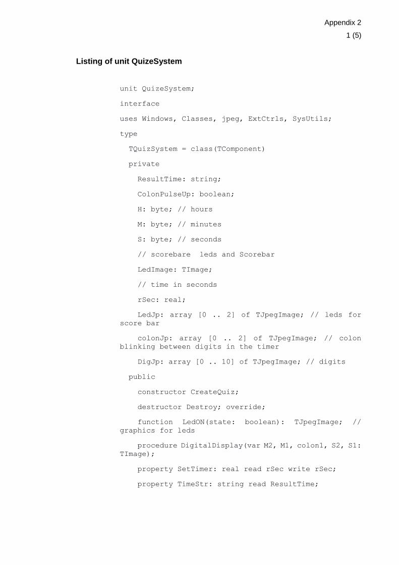
Listing of unit QuizeSystem
unit QuizeSystem;
interface
uses Windows, Classes, jpeg, ExtCtrls, SysUtils;
type
TQuizSystem = class(TComponent)
private
ResultTime: string;
ColonPulseUp: boolean;
H: byte; // hours
M: byte; // minutes
S: byte; // seconds
// scorebare leds and Scorebar
LedImage: TImage;
// time in seconds
rSec: real;
LedJp: array [0 .. 2] of TJpegImage; // leds for
score bar
colonJp: array [0 .. 2] of TJpegImage; // colon
blinking between digits in the timer
DigJp: array [0 .. 10] of TJpegImage; // digits
public
constructor CreateQuiz;
destructor Destroy; override;
function LedON(state: boolean): TJpegImage; //
graphics for leds
procedure DigitalDisplay(var M2, M1, colon1, S2, S1:
TImage);
property SetTimer: real read rSec write rSec;
property TimeStr: string read ResultTime;

Appendix 2
2 (5)
property ColonPulse: boolean read ColonPulseUp
write ColonPulseUp;
end;
var
Quizzes: array [0 .. 12] of TJpegImage;
function GetResourceAsJpeg(const resname: string):
TJpegImage;
external 'Funcom.dll';
implementation
constructor TQuizSystem.CreateQuiz;
var
i: byte;
const
ROWNUMBER = 12;
begin
H := 0;
M := 0;
S := 0;
rSec := 0;
ColonPulseUp := true;
ResultTime := inttostr(H) + ':' + inttostr(M) + ':' +
inttostr(S);
try
// loading from resourcefile lpg - digits, colon,
leds
LedJp[0] := TJpegImage.Create;
if LedJp[0] <> nil then
LedJp[0] := GetResourceAsJpeg('JpgLedsOFF');
LedJp[1] := TJpegImage.Create;
if LedJp[1] <> nil then
LedJp[1] := GetResourceAsJpeg('JpgLedsON');
Appendix 2
3 (5)
colonJp[0] := TJpegImage.Create;
if colonJp[0] <> nil then
colonJp[0] := GetResourceAsJpeg('JpgColonOFF');
colonJp[1] := TJpegImage.Create;
if colonJp[1] <> nil then
colonJp[1] := GetResourceAsJpeg('JpgColonON');
for i := 0 to 9 do
begin
DigJp[i] := TJpegImage.Create;
if DigJp[i] <> nil then
DigJp[i] := GetResourceAsJpeg('jpg' +
inttostr(i));
end;
for i := 0 to 11 do
begin
Quizzes[i] := TJpegImage.Create;
if Quizzes[i] <> nil then
Quizzes[i] := GetResourceAsJpeg('quiz' +
inttostr(i));
end;
except exit; end; end;
destructor TQuizSystem.Destroy;
var
i: byte;
begin
inherited Destroy;
if LedJp[0] <> nil then
LedJp[0].Free;
if LedJp[1] <> nil then
LedJp[1].Free;
Appendix 2
4 (5)
if colonJp[0] <> nil then
colonJp[0].Free;
if colonJp[1] <> nil then
colonJp[1].Free;
for i := 0 to 9 do
begin
if DigJp[i] <> nil then
DigJp[i].Free;
end;
LedImage.Free;
end;
function TQuizSystem.LedON(state: boolean):
TJpegImage;
begin
if state then
Result := LedJp[1]
else
Result := LedJp[0];
end;
procedure TQuizSystem.DigitalDisplay(var M2, M1,
colon1, S2, S1: TImage);
var
Sec: byte;
begin
Sec := trunc(rSec);
H := Sec div 3600;
M := Sec div 60 - H * 60;
S := Sec - (H * 3600 + M * 60);
if (M <= 99) and (S <= 99) then
begin
if not DigJp[M div 10].Empty then
Appendix 2
5 (5)
M1.Picture.Graphic := DigJp[M mod 10];
if not DigJp[M mod 10].Empty then
M2.Picture.Graphic := DigJp[M div 10];
if not DigJp[S div 10].Empty then
S1.Picture.Graphic := DigJp[S mod 10];
if not DigJp[S mod 10].Empty then
S2.Picture.Graphic := DigJp[S div 10];
end;
if ColonPulseUp then
begin
colon1.Picture.Graphic := colonJp[1];
ColonPulseUp := False;
end
else
begin
colon1.Picture.Graphic := colonJp[0];
ColonPulseUp := true;
end;
if rSec > 0 then
rSec := rSec - 0.5;
ResultTime := inttostr(H) + ':' + inttostr(M) + ':'
+ inttostr(S);
end; end.
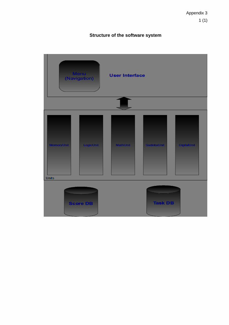
Appendix 3
1 (1)
Structure of the software system
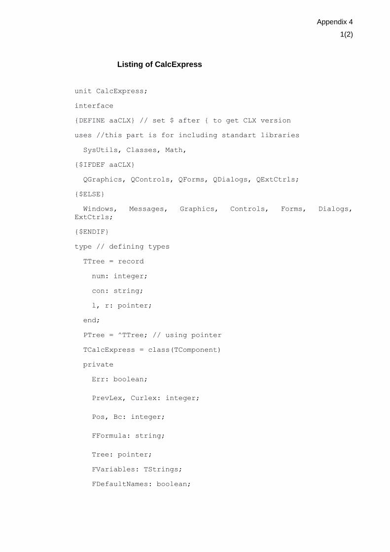
Appendix 4
1(2)
Listing of CalcExpress
unit CalcExpress;
interface
{DEFINE aaCLX} // set $ after { to get CLX version
uses //this part is for including standart libraries
SysUtils, Classes, Math,
{$IFDEF aaCLX}
QGraphics, QControls, QForms, QDialogs, QExtCtrls;
{$ELSE}
Windows, Messages, Graphics, Controls, Forms, Dialogs,
ExtCtrls;
{$ENDIF}
type // defining types
TTree = record
num: integer;
con: string;
l, r: pointer;
end;
PTree = ^TTree; // using pointer
TCalcExpress = class(TComponent)
private
Err: boolean;
PrevLex, Curlex: integer;
Pos, Bc: integer;
FFormula: string;
Tree: pointer;
FVariables: TStrings;
FDefaultNames: boolean;
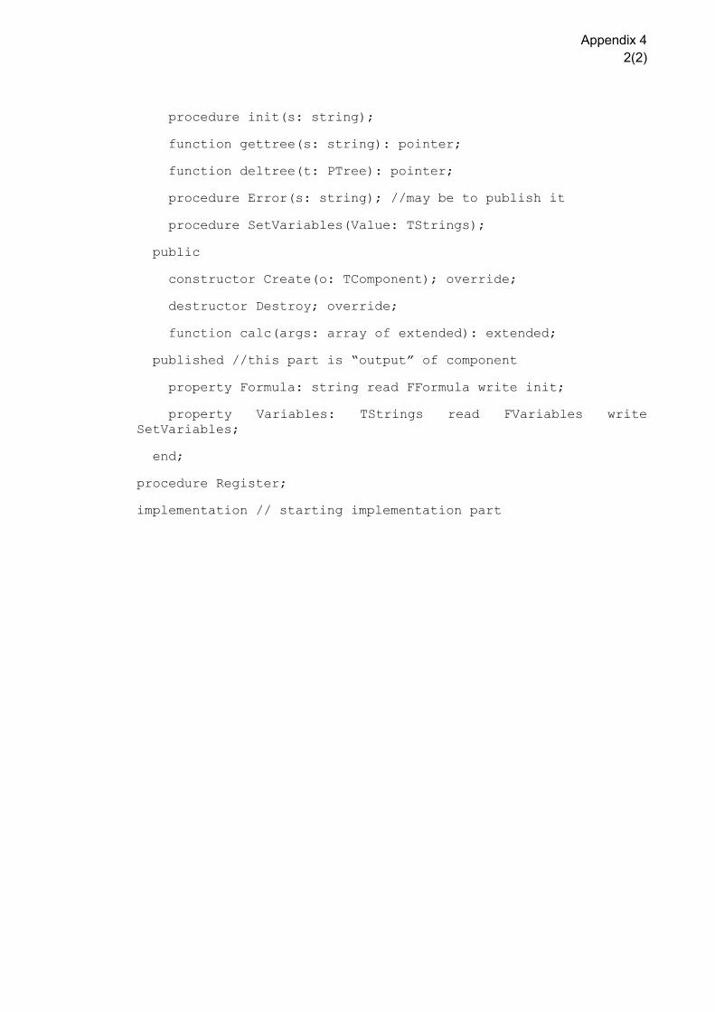
Appendix 4
2(2)
procedure init(s: string);
function gettree(s: string): pointer;
function deltree(t: PTree): pointer;
procedure Error(s: string); //may be to publish it
procedure SetVariables(Value: TStrings);
public
constructor Create(o: TComponent); override;
destructor Destroy; override;
function calc(args: array of extended): extended;
published //this part is “output” of component
property Formula: string read FFormula write init;
property Variables: TStrings read FVariables write
SetVariables;
end;
procedure Register;
implementation // starting implementation part
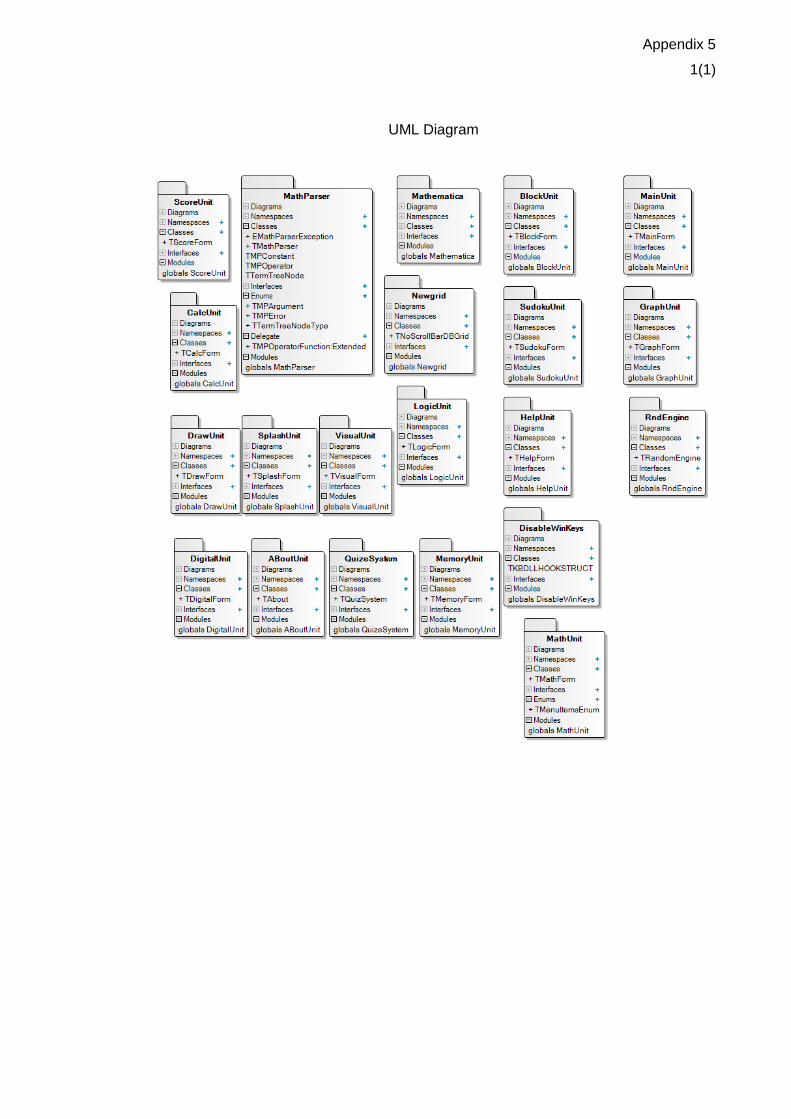
Appendix 5
1(1)
UML Diagram