eclipse705heavyduty be57-102 - rom devicesromdevices.com/pdf/traductoare_nivel/eclipse3h.pdf ·...
TRANSCRIPT

Heavy Duty Guided Wave RadarLevel Transmitter
Overfill safe for clean and dirty liquids
www.eclipse.magnetrol.com
D E S C R I P T I O NThe Eclipse 705 Transmitter is a loop-powered, 24 V DCliquid-level transmitter based on the revolutionary GuidedWave Radar (GWR) technology. Encompassing a numberof significant engineering accomplishments, this leadingedge level transmitter is designed to provide measurementperformance well beyond that of many traditional technolo-gies, as well as “through-air” radars.The innovative enclosure is a first in the industry, orientingdual compartments (wiring and electronics) in the sameplane, and angled to maximize ease of wiring, configuration,set-up and data display.This single transmitter can be used with all probe types andoffers enhanced reliability, for use in SIL 2 / SIL 3 loops.
F E AT U R E S* “REAL LEVEL”, measurement not affected by media vari-
ables eg. dielectrics, pressure, density, pH, viscosity, ...* Easy bench configuration - no need for level simulation.* Two-wire, intrinsically safe loop powered level transmitter.* 20-point custom strapping table for volumetric output.* 360° rotatable housing can be dismantled without depres-
surising the vessel via “Quick connect/disconnect” probecoupling.
* Two-line, 8-character LCD and 3-button keypad.* Probe designs: up to +425 °C / 431 bar (+800 °F / 6250 psi).* Saturated steam applications up to 155 bar @ +345 °C
(2250 psi @ +650 °F).* Cryogenic applications down to -196 °C (-320 °F).* Integral or remote electronics.* Suited for SIL 2 / SIL 3 Loops (full FMEDA report avail-
able).
A P P L I C AT I O N SMEDIA: Liquids or slurries; hydrocarbons to water-basedmedia (dielectric 1,4 - 100).VESSELS: Most process or storage vessels.CONDITIONS: All level measurement and control applicationsincluding process conditions exhibiting visible vapours, foam,surface agitation, bubbling or boiling, high fill/empty rates, lowlevel and varying dielectric media or specific gravity.
Ask for your free copy of the Eclipse® 705 performance reportby WIB/Evaluation International (SIREP)/EXERA.
Worldwide level and flow solutions
A G E N C Y A P P R O VA L S
� Probe is intrinsically safe to ATEX II 1 G EEx ia IIC T6 and can be usedin zone 0, on flammable liquids.
� Foundation Fieldbus™ and Profibus PA™ units.� Consult factory for proper model numbers and classifications.
® 705
Eclipse withlarge coaxialGWR probe
Agency ApprovalsATEX II 3 (1) G EEx nA [ia] IIC T6, non sparking �
II 3 (1) G EEx nA [nL] [ia] IIC T6, FNICO – non incendive ��
II 1 G Ex ia IIC T4 Ga, intrinsically safeII 1 G Ex ia IIC T4 Ga, FISCO – intrinsically safe�
II 1/2 G Ex d[ia Ga] IIC T6 GbII 1/2 D Ex t[ia Da] IIIC T85°C Db IP66
Lloyds Primary level safety device for steamdrumsconform to- EN 12952-11 (water tube boilers)- EN 12953-9 (shell boilers)
TÜV WHG § 63, overfill preventionAIB VLAREM II – 5.17.7LRS Lloyds Register of Shipping (marine applications)FM/CSA�
IEC� Ex d[ia Ga] IIC T6 GbEx t[ia Da] IIIC T85°C Db IP66
Russian Authorisation Standards�
Other approvals are available, consult factory for more details

2
T E C H N O L O G YLevelEclipse® Guided Wave Radar is based upon the technologyof TDR (Time Domain Reflectometry). TDR utilises pulsesof electromagnetic energy transmitted down a wave guide(probe). When a pulse reaches a liquid surface that has ahigher dielectric constant than the air (εr of 1) in which it istraveling, the pulse is reflected. The travelling time of thepulse is measured via ultra high speed timing circuitry thatprovides an accurate measure of the liquid level. Even afterthe pulse is reflected from the upper surface, some of theenergy continues down the GWR probe through the upperliquid. The pulse is again reflected when it reaches the high-er dielectric lower liquid, as shown in the illustration.
InterfaceThe Eclipse® 705, is capable of measuring both an upperliquid level and an interface liquid level. It is required that theupper liquid has a dielectric constant between 1,4 and 5,and the lower liquid has a dielectric constant greater than15. A typical application would be oil over water, with theupper layer of oil being non-conductive (εr ± 2,0), and thelower layer of water being very conductive (εr ± 80). Thethickness of the upper layer must be > 50 mm (2"). Themaximum upper layer is limited to the length of the 7MTGWR probe, which is available in lengths up to 6,1 m (240").
Air εεr = 1
Reference signal
Time
Upper levelsignal > 50 mm
(2")
< 50 mm (2")
Interface level signal
Low dielectric medium(eg. oil, εεr = 2)
high dielectric medium(eg. water, εεr = 80)
FDT technology provides an open communication inter-face between field instruments of various communicationprotocols and the host/ DCS system. The DTM driver istypical for one type of instrument and delivers the full func-tionality of the device added with graphical user interfacevia a laptop or PC. Magnetrol transmitters use the freeshareware PACTware™ software to support DTM driversand the FDT functionality. Via PACTware™ it becomeseasy to configure, monitor and diagnose a Magnetroltransmitter from distance or even to call for factory assis-tance over the internet via the supply of screenshots ofecho curves and trending graphs. Magnetrol DTM libraryHART® has passed the dtmINSPECTOR, the official FDTinteroperability test and certification tool. The MagnetrolDTMʼs are free of charge and can be downloaded fromwww.magnetrol.com or obtained via CD Rom from yournearest Magnetrol contact.
PA C T w a r e ™ P C S O F T WA R E P R O G R A M
ReflectedPulse
InitialPulse
Air εεr = 1
Liquid εεr > 1,4
TransmittedPulse
PACTware™ CD withDTM drivers
Magnetrol recom-mends the VIATOR®
USB HART® Interfacefrom MACTek®
Corporation.
Emulsion layersAs emulsion layers can decrease the strength of the reflect-ed signal, the Eclipse® 705 should only be utilised in thoseinterface applications that have clean, distinct layers. TheEclipse® 705 will tend to detect the top of the emulsion layer.Contact the factory for application assistance.
Emulsion layer

3
In order to match the proper Eclipse transmitter with the proper external cage, consider the following:- Type of application – use the applicable GWR probe, see selection guide.- Overfill proof: Overfilling occurs when the level rises above the max level – radar based equipment may provide erro-
neous output in this zone unless an adapted design is used. GWR probes without top transition zone (e.g. 7MR, 7MD,7MT) are always safe to use – only in cases where the application demands for a different probe type, other selectionsshould be considered and the recommended precautions followed.
- Min cage size: Refer to individual probe info.
Measuring range:min 300 mm (11.81")max 5700 mm (224")
E
Probe Insertion Length =+ measuring range + FE
20 mA / 100 %
4 mA / 0 %min 25 mm (1")
Body connection
DisplacerLength
F
PH
Eclipse® has proven to be the perfect replacement for exist-ing torque tube transmitters. In hundreds of applicationsaround the globe, customers have found Eclipse® GuidedWave Radar superior to torque tube transmitters:• Cost:
A new Eclipse® costs only slightly more than rebuilding anaging torque tube.
• Installation:No field calibration is necessary; it can be configured inminutes with no level movement. Pre-configuration fromfactory is free of charge.
• Performance:Eclipse® is not affected by changes in specific gravity ordielectric.
• Ease of replacement:Proprietary flanges are offered so existing chamber/cages can be used.
Before After
R E P L A C E M E N T O F D I S P L A C E R T R A N S M I T T E R
Manufacturer Type Process connection Displacer lengthinches (mm)
Probe length�
mm (inches)Magnetrol® EZ & PN
Modulevel® ANSI/DIN flange ≥ 14" (356) Displacer + 178 (7)
Masoneilan® Series 1200Proprietary flange ≥ 14" (356) Displacer + 203 (8)ANSI/DIN flange ≥ 16" (406) Displacer + 203 (8)
Fisher® series2300 & 2500
249B, 259B,249C cages Proprietary flange ≥ 14" (356) Displacer + 254 (10)
other cages ANSI flange ≥ 14" (356) consult factoryEckhardt® Series 134,144 ANSI/DIN flange ≥ 14" (356) consult factory
Tokyo Keiso® FST-3000ANSI/DIN flange H = 11.8" (300) Displacer + 229 (9)ANSI/DIN flange ≥ H = 19.7" (500) Displacer + 229 (9)
Indicative probe length for replacing displacer transmittersBelow table helps to define the GWR probe length based upon the length of the most common displacer transmitters. Consultthe flange selection guide on the next page.
� Round down resulting calculation to the nearest cm.

The maintenance of coaxial GWR probes in applicationssuffering from buildup, crystallization or condensation cansignificantly be improved by using aflushing connection. A flushing connec-tion is a metal extension with a vent,welded above the process connection.Via the vent it is possible to purge theinside of the coaxial GWR probe duringa maintenance routine. The bestapproach to defeat the effects of con-densation or crystallization is to installadequate insulation or heattracing (steam or electrical).A flushing connection is nosubstitute for proper mainte-nance but will help toreduce/optimize the fre-quency of the maintenanceroutines.
4
Figure 1 Figure 2 Figure 3
In addition to Magnetrolʼs Torque Tube Cage Flangeoptions, the Eclipse® 705 transmitter and 7EK GWRprobe/cage can also be used in replacing existingTop/Bottom and Top/Side torque tube installations.After removal of the existing torque tube cage assembly(controller, displacer and cage), Eclipse Guided WaveRadar may then be installed directly in its place. Severalmodels are available for some of the major torque tube dis-placer transmitter manufacturers. Because the Model 7EKprobe/cage mounting dimensions and measuring rangesmatch the original manufacturerʼs specification, no re-pip-ing is necessary.
Before After
A U R O R A ™Aurora® is the innovative combination of the Eclipse®
Guided Wave Radar and a Magnetic Level Indicator(MLI). The MLI indicator rail offers the Eclipse ahighly visible level indication that may obsolete theneed for local indicators. The integration of thesetwo independent technologies provides an excellentredundancy in one integrated design. With Aurora® itis even possible to plan maintenance ahead.Maintenance becomes needed when build up in aninstallation has surpassed the allowable limit. Buildup on the float inside the MLI cage will force it to sinkdeeper in the liquid while the measurement of theEclipse will not see any build up until its both leadelements are completely clugged. In this way, thefloat will indicate a lower level versus the real levelmeasured by the Eclipse. The degree of deviationbetween both read outs is a worthwhile tool to deter-mine the real need for maintenance. For more details – consult bulletin BE 57-138.
C A G E SEclipse can be built into cages as small asDN 50 / 2", depending on probe type. When anew cage is needed, it can be ordered togetherwith the Eclipse. Magnetrol has a long traditionin offering cost effective cages. Magnetrol cagescomply with PED regulations and are availablewith a wide variety of options.
Measuring span 30-610 cm (12-240") �
Materials of constructionCarbon steel or 316/316L (1.4401/1.4404)stainless steel
Process connection sizes 1", 1 1/2", 2"Process connection ratings 150#-2500# ANSIConfigurations Side-Side and Side-BottomProcess pressures Up to 431 bar (6250 psi) �Process temperatures Up to +425 °C (+800 °F) �
� Limitations are defined per selected GWR probe. For more details – consult bulletin BE 57-140.
P R O P R I E TA R Y F L A N G E S
Ø 229(9.0)
32(1.25)
Fisher 249B/259B (600 lbs), carbon steel
133(5.23) 6
(.22)
Ø 184(7.25)
Ø 22(.875)
45°
Ø 143(5.625)
29(1.125)
Fisher 249C (600 lbs), 316 stainless steel
86(3.375) 5
(.188)
Ø 121(4.750)
Ø 11(.438)
45°
Ø 191(7.50)
32(1.25)
Masoneilan (600 lbs), 316 carbon steel
102(4.00) 6
(.25)
Ø 149(5.875)
Ø 22(.875)
45°
R E P L A C E M E N T O F T O P / B O T T O MC A G E S
F L U S H I N G C O N N E C T I O N

S E L E C T I O N G U I D E
5
Dielectric limit
Coaxial GWR probes - max viscosity 2000 mPa.s (cP) (except 7MS: max 500 mPa.s (cP))
GWR ProbeTemperature limitsApplication
εr 1,4 - 100 7MR/7MM-40 °C up to +200 °C max 70 bar Yes Yes NoLevel
εr 1,4 - 100 7MG-40 °C up to +200 °C max 70 bar Yes Yes YesLevel/Interface
Cage GWR probe - max viscosity 10.000 mPa.s (cP)
εr 1,4 - 100� 7MD/7ML-196 °C up to +425 °C max 431 bar Full Yes NoHigh temp / High pressureInterface
εr 10 - 100 7MSup to +345 °C max 155 bar Yes No� NoSaturated steam
εr 1,4 - 100 7MT/7MN-40 °C up to +200 °C max 70 bar Yes Yes NoInterface
ApplicationsPressure Vacuum Overfill Foam
� safe �
� Each Eclipse probe can be used for vacuum service (negative pressure) but only the Borosilicate GWR probes (7MD/7ML) are suited for full vacuum condi-tions (Helium leak < 10-8 cc/s @ 1 bar abs.)
� Eclipse is ideally suited to be used on foaming applications but in specific conditions where dense foam can enter/hydrate in the stilling well, coaxial GWRprobes are not recommended.
� Depending spacer. See model selection 7MD/7ML GWR probe.� Consult factory for overfill applications.
Cage GWR probe for dirty liquidsThe cage GWR probe is a single rod GWR probe whichuses an existing or new cage, bridle or schedule pipe still-well to re-create the same propagation of signal of a coaxi-al GWR probe. Cage GWR probes are suited for 2", 3" or 4"size diam. and use an impedance matching part that alignsin the same way with the characteristic impedance of a stan-dard coaxial style GWR probe. Cage GWR probes are over-fill safe and offer the same performance of coaxial GWRprobes.
Large coaxial GWR probes for clean liquidsThe large diam. GWR probes can be generally used formost applications. They can be installed directly in the tankas well as in by-pass cages, schedule pipe stillwells or bri-dles. Its more rugged construction allows eliminating spac-ers in applications where higher risk of build exists.

6
E X P E D I T E S H I P P L A N ( E S P )Several models are available for quick shipment, within max. 4 weeks after factory receipt of purchase order, through theExpedite Ship Plan (ESP).Models covered by ESP service are conveniently colour coded in the selection data charts.To take advantage of ESP, simply match the colour coded model number codes (standard dimensions apply).ESP service may not apply to orders of ten units or more. Contact your local representative for lead times on larger volumeorders, as well as other products and options.
S E L E C T I O N D ATAA complete measuring system consists of:1.Eclipse transmitter head/electronics2.Eclipse 705 GWR probe3.Free of charge: Magnetrol master C.D. with Eclipse 705 DTM (PACTware™). Order code: 090-BE59-200 (included in each
order).4.Option: MACTek Viator USB HART® interface: order code: 070-3004-002
D I M E N S I O N S i n m m ( i n c h e s )
83(3.28)
105(4.12)
108(4.25)
95(3.75)102
(4.00)
89(3.50)
70(2.75)
2 holesØ 9,5 (0.37)
2 cableentries
19(0.75) 840 or 3660
(33 or 144)
102(4.00)
214 (8.43)
126 (4.94)
111(4.38)
45° View
45°
Eclipse Housing,(45° View)
Remote ElectronicsIntegral Electronics
E L E C T R I C A L W I R I N G
0 % 100 %
Standard shielded twisted cable(recommendedbut not neededwhen wired as perNAMUR NE 21 forfield strenghts upto 10 V/m).
Ex Non Ex
83(3.28)
105(4.12)
256(10.08)
102(4.00)
2 cableentries
45°
HART® key
Galvanic Barrier (only needed for intrinsically safe units):HART®: max. 28,4 V DC @ 94 mAFoundation Fieldbus™ / Profibus PA™: max. 17,5 V DC @ 380 mA

7
1. Order code for ECLIPSE 705 transmitter head/electronics
7 50 5
POWER
complete order code for ECLIPSE 705 transmitter head/electronics
5 24 V DC, two wire loop powered
BASIC MODEL NUMBER7 0 5 Eclipse 705 guided wave radar transmitter
OUTPUT AND ELECTRONICS
CABLE ENTRY1 M20 x 1,5 (2 entries - 1 plugged)0 3/4" NPT (2 entries - 1 plugged)
ACCESSORIESA Digital display and keypad0 Blind transmitter (no display/keypad)
1 0 4-20 mA with HART® – standard electronics (SFF of 85.4%)1 A 4-20 mA with HART® – SIL enhanced electronics (SFF of 91%) - certified2 0 Foundation Fieldbus™ communication3 0 Profibus PA™ communication
MOUNTING / HOUSING MATERIAL / APPROVAL�
1 1 WeatherproofA 1 ATEX intrinsically safe (digit 5 = 1) / ATEX FISCO (digit 5 = 2 or 3)C 1 ATEX flameproof enclosureE 1 ATEX non sparking (digit 5 =1) / ATEX FNICO (digit 5 = 2 or 3)
Integral mount electronicsCast aluminium
1 2 WeatherproofA 2 ATEX intrinsically safe (digit 5 = 1) / ATEX FISCO (digit 5 = 2 or 3)C 2 ATEX flameproof enclosureE 2 ATEX non sparking (digit 5 =1) / ATEX FNICO (digit 5 = 2 or 3)
Cast SST
2 1 WeatherproofB 1 ATEX intrinsically safe (digit 5 = 1) / ATEX FISCO (digit 5 = 2 or 3)D 1 ATEX flameproof enclosureF 1 ATEX non sparking (digit 5 =1) / ATEX FNICO (digit 5 = 2 or 3)
84 cm (33") remote mount electronicsCast aluminium
2 2 WeatherproofB 2 ATEX intrinsically safe (digit 5 = 1) / ATEX FISCO (digit 5 = 2 or 3)D 2 ATEX flameproof enclosureF 2 ATEX non sparking (digit 5 =1) / ATEX FNICO (digit 5 = 2 or 3)
Cast SST
2 7 WeatherproofB 7 ATEX intrinsically safe (digit 5 = 1) / ATEX FISCO (digit 5 = 2 or 3)D 7 ATEX flameproof enclosureF 7 ATEX non sparking (digit 5 =1) / ATEX FNICO (digit 5 = 2 or 3)
3,66 m (144") remote mount electronics (consult factory for applications with εεr < 10)Cast aluminium
2 8 WeatherproofB 8 ATEX intrinsically safe (digit 5 = 1) / ATEX FISCO (digit 5 = 2 or 3)D 8 ATEX flameproof enclosureF 8 ATEX non sparking (digit 5 =1) / ATEX FNICO (digit 5 = 2 or 3)
Cast SST
X = product with a specific customer requirement
� For IEC approval, use ATEX approval and clearly request IEC nameplate.

8
M O U N T I N G – 7 M R / 7 M M / 7 M T / 7 M N
D I M E N S I O N S i n m m ( i n c h e s )
256(10.08)
102(4.00)
168 (6.61)
Large 7MR / 7MTwith flanged connection
83(3.28)
105(4.12)
2 cableentries
45°
ProbeInsertionLength
256(10.08)
102(4.00)
206 (8.11)1/4" NPTplugged
Large 7MM / 7MNwith flanged connection
83(3.28)
105(4.12)
2 cableentries
45°
ProbeInsertionLength
Coaxial GWR Probe,End View
Overfill safe and Overfill proofEclipse 7MR, 7MM, 7MT and 7MN coaxial type GWRprobes are “Overfill safe” in use and “Overfill proof”certified. Overfill safe means that the unit is capable to measure upto the process connection. Units with “non overfill safe”probes use software to ignore level readings in the block-ing distance or transitioning zone. When level rises toohigh in this zone, the unit may consider the end of probereflection as the real level and may report an empty vesselinstead of an overfilling vessel. Overfill proof protection (such as WHG or VLAREM) cer-tifies reliable operation when the transmitter is used asoverfill alarm but assumes that the installation is designedin such way that the vessel/ cage cannot overfill.
Venting holesfor 7MR/7MM
AB C
D
E
Venting holesfor 7MT/7MN
Dim. mm (inch)A 305 (12)B Ø 12,7 (0.5)C 25,4 (1)
D45 (1.75) - SST49 (1.93) - Hast. Cand Monel
E 16 (0.63)
B
9
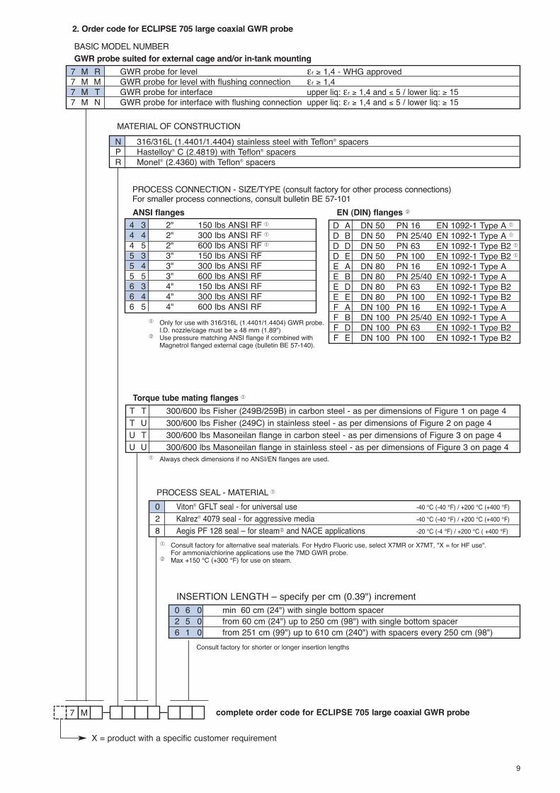
2. Order code for ECLIPSE 705 large coaxial GWR probe
7 M
MATERIAL OF CONSTRUCTION
complete order code for ECLIPSE 705 large coaxial GWR probe
N 316/316L (1.4401/1.4404) stainless steel with Teflon® spacersP Hastelloy® C (2.4819) with Teflon® spacersR Monel® (2.4360) with Teflon® spacers
BASIC MODEL NUMBERGWR probe suited for external cage and/or in-tank mounting
7 M R GWR probe for level εr ≥ 1,4 - WHG approved7 M M GWR probe for level with flushing connection εr ≥ 1,47 M T GWR probe for interface upper liq: εr ≥ 1,4 and ≤ 5 / lower liq: ≥ 157 M N GWR probe for interface with flushing connection upper liq: εr ≥ 1,4 and ≤ 5 / lower liq: ≥ 15
PROCESS CONNECTION - SIZE/TYPE (consult factory for other process connections)For smaller process connections, consult bulletin BE 57-101
4 3 2" 150 lbs ANSI RF �
4 4 2" 300 lbs ANSI RF �
4 5 2" 600 lbs ANSI RF �
5 3 3" 150 lbs ANSI RF5 4 3" 300 lbs ANSI RF5 5 3" 600 lbs ANSI RF6 3 4" 150 lbs ANSI RF6 4 4" 300 lbs ANSI RF6 5 4" 600 lbs ANSI RF
ANSI flangesD A DN 50 PN 16 EN 1092-1 Type A �
D B DN 50 PN 25/40 EN 1092-1 Type A �
D D DN 50 PN 63 EN 1092-1 Type B2 �
D E DN 50 PN 100 EN 1092-1 Type B2 �
E A DN 80 PN 16 EN 1092-1 Type AE B DN 80 PN 25/40 EN 1092-1 Type AE D DN 80 PN 63 EN 1092-1 Type B2E E DN 80 PN 100 EN 1092-1 Type B2F A DN 100 PN 16 EN 1092-1 Type AF B DN 100 PN 25/40 EN 1092-1 Type AF D DN 100 PN 63 EN 1092-1 Type B2F E DN 100 PN 100 EN 1092-1 Type B2
EN (DIN) flanges �
T T 300/600 lbs Fisher (249B/259B) in carbon steel - as per dimensions of Figure 1 on page 4T U 300/600 lbs Fisher (249C) in stainless steel - as per dimensions of Figure 2 on page 4U T 300/600 lbs Masoneilan flange in carbon steel - as per dimensions of Figure 3 on page 4U U 300/600 lbs Masoneilan flange in stainless steel - as per dimensions of Figure 3 on page 4
Torque tube mating flanges �
INSERTION LENGTH – specify per cm (0.39") increment
PROCESS SEAL - MATERIAL �0 Viton® GFLT seal - for universal use -40 °C (-40 °F) / +200 °C (+400 °F)2 Kalrez® 4079 seal - for aggressive media -40 °C (-40 °F) / +200 °C (+400 °F)8 Aegis PF 128 seal – for steam� and NACE applications -20 °C (-4 °F) / +200 °C ( +400 °F)
� Consult factory for alternative seal materials. For Hydro Fluoric use, select X7MR or X7MT, "X = for HF use".For ammonia/chlorine applications use the 7MD GWR probe.
� Max +150 °C (+300 °F) for use on steam.
� Always check dimensions if no ANSI/EN flanges are used.
� Only for use with 316/316L (1.4401/1.4404) GWR probe.I.D. nozzle/cage must be ≥ 48 mm (1.89")
� Use pressure matching ANSI flange if combined withMagnetrol flanged external cage (bulletin BE 57-140).
Consult factory for shorter or longer insertion lengths
X = product with a specific customer requirement
0 6 0 min 60 cm (24") with single bottom spacer2 5 0 from 60 cm (24") up to 250 cm (98") with single bottom spacer6 1 0 from 251 cm (99") up to 610 cm (240") with spacers every 250 cm (98")

10
D I M E N S I O N S i n m m ( i n c h e s )
Overfill safe and Overfill protectionEclipse 7MD and 7ML coaxial type GWR probes are“Overfill safe” in use and “Overfill proof” certified.Overfill safe means that the unit is capable to measure upto the process connection. Units with “non overfill safe”probes use software to ignore level readings in the block-ing distance or transitioning zone. When level rises too highin this zone, the unit may consider the end of probe reflec-tion as the real level and may report an empty vesselinstead of an overfilling vessel. Overfill proof protection (such as WHG or VLAREM) cer-tifies reliable operation when the transmitter is used asoverfill alarm but assumes that the installation is designedin such way that the vessel/ cage cannot overfill.
Large 7MD with flanged connection
277 (10.90)
83(3.28)
105(4.12)
256(10.08)
102(4.00)
2 cableentries
45°
ProbeInsertionLength
M O U N T I N G – 7 M D / 7 M L
Large 7ML with flanged connection
375(14.76)
83(3.28)
105(4.12)
256(10.08)
102(4.00)
2 cableentries
45°
ProbeInsertionLength
1/4" NPTplugged
Coaxial GWR Probe,End View
Venting holesfor 7MD/7ML - level
AC
D
E
Venting holesfor 7MD/7ML - interface
(order per "X" description)
BB Dim. mm (inch)
A 305 (12)B Ø 12,7 (0.5)C 25,4 (1)
D45 (1.75) - SST49 (1.93) - Hast. Cand Monel
E 16 (0.63)

11
2. Order code for ECLIPSE 705 large High Temperature / High Pressure coaxial GWR probe
7 NM complete order code for ECLIPSE 705 large High Temperature / High Pressure coaxial GWR probe
PROCESS SEAL MATERIALN Borosilicate / Inconel® X-750 seal – for non steam applications -196 °C (-320 °F) / +345 °C (+650 °F)
PROCESS CONNECTION - SIZE/TYPE (consult factory for other process connections)For smaller process connections, consult bulletin BE 57-101
4 3 2" 150 lbs ANSI RF �
4 4 2" 300 lbs ANSI RF �
4 5 2" 600 lbs ANSI RF �
4 K 2" 600 lbs ANSI RJ �
5 3 3" 150 lbs ANSI RF5 4 3" 300 lbs ANSI RF5 5 3" 600 lbs ANSI RF5 K 3" 600 lbs ANSI RJ5 L 3" 900 lbs ANSI RJ5 M 3" 1500 lbs ANSI RJ5 N 3" 2500 lbs ANSI RJ6 3 4" 150 lbs ANSI RF6 4 4" 300 lbs ANSI RF6 5 4" 600 lbs ANSI RF6 K 4" 600 lbs ANSI RJ6 L 4" 900 lbs ANSI RJ6 M 4" 1500 lbs ANSI RJ6 N 4" 2500 lbs ANSI RJ
ANSI flangesD A DN 50 PN 16 EN 1092-1 Type A �
D B DN 50 PN 25/40 EN 1092-1 Type A �
D D DN 50 PN 63 EN 1092-1 Type B2 �
D E DN 50 PN 100 EN 1092-1 Type B2 �
E A DN 80 PN 16 EN 1092-1 Type AE B DN 80 PN 25/40 EN 1092-1 Type AE D DN 80 PN 63 EN 1092-1 Type B2E E DN 80 PN 100 EN 1092-1 Type B2E F DN 80 PN 160 EN 1092-1 Type B2E G DN 80 PN 250 EN 1092-1 Type B2E H DN 80 PN 320 EN 1092-1 Type B2E J DN 80 PN 400 EN 1092-1 Type B2F A DN 100 PN 16 EN 1092-1 Type AF B DN 100 PN 25/40 EN 1092-1 Type AF D DN 100 PN 63 EN 1092-1 Type B2F E DN 100 PN 100 EN 1092-1 Type B2F F DN 100 PN 160 EN 1092-1 Type B2F G DN 100 PN 250 EN 1092-1 Type B2F H DN 100 PN 320 EN 1092-1 Type B2F J DN 100 PN 400 EN 1092-1 Type B2
EN (DIN) flanges �
T T 300/600 lbs Fisher (249B/259B) in carbon steel - as per dimensions of Figure 1 on page 4T U 300/600 lbs Fisher (249C) in stainless steel - as per dimensions of Figure 2 on page 4U T 300/600 lbs Masoneilan flange in carbon steel - as per dimensions of Figure 3 on page 4U U 300/600 lbs Masoneilan flange in stainless steel - as per dimensions of Figure 3 on page 4
Torque tube mating flanges �
X = product with a specific customer requirement
� Always check dimensions if no ANSI/EN flanges are used.
7 M D Large HTHP GWR probe for level/interface - max +345 °C εr ≥ 1,7�
7 M L Large HTHP GWR probe for level/interface with flushing connection - max +345 °C εr ≥ 1,7�
� Consult bulletin BE 57-101 for lower εr and higher temp. up to +430 °C.εr ≥ 1,4 for GWR probes with single bottom spacer.For interface measurement: order per "X" description; upper liquid: εr ≥ 1,4 or 1,7 and ≤ 5 / lower liquid: εr ≥ 15
MATERIAL OF CONSTRUCTIONN 316/316L (1.4401/1.4404) stainless steel with PEEK spacersP Hastelloy® C (2.4819) with PEEK spacersR Monel® (2.4360) with PEEK spacers
� Only for use with 316/316L (1.4401/1.4404) GWR probe.I.D. nozzle/cage must be ≥ 48 mm (1.89")
� Use pressure matching ANSI flange if combined withMagnetrol flanged external cage (bulletin BE 57-140).
INSERTION LENGTH – specify per cm (0.39") increment
Consult factory for shorter or longer insertion lengths
0 6 0 min 60 cm (24") with single bottom spacer2 5 0 from 60 cm (24") up to 250 cm (98") with single bottom spacer6 1 0 from 251 cm (99") up to 610 cm (240") with spacers every 250 cm (98")

12
D I M E N S I O N S i n m m ( i n c h e s )
ProbeInsertionLength
187(7.37)
Washer
Teflon spacer
Ø 13 (0.50) rodProbe
InsertionLength
PEEK spacer
Ø 19 (0.75) rod
Ø 71 (2.80) Ø 95 (3.77)
ProbeInsertionLength
PEEK spacer
Ø 25 (1) rod
7MG - 2" cagemax 6,1 m (240")
Spacer (end view)
For ordering of a new cage, consult bulletin BE 57-140
Sectionized
7MG - 3" cagemax 6,1 m (240")
7MG - 4" cagemax 6,1 m (240")
187(7.37)
187(7.37)
49(1.90)
Spacer (end view)
71 (2.80)
Spacer (end view)94 (3.70)
13
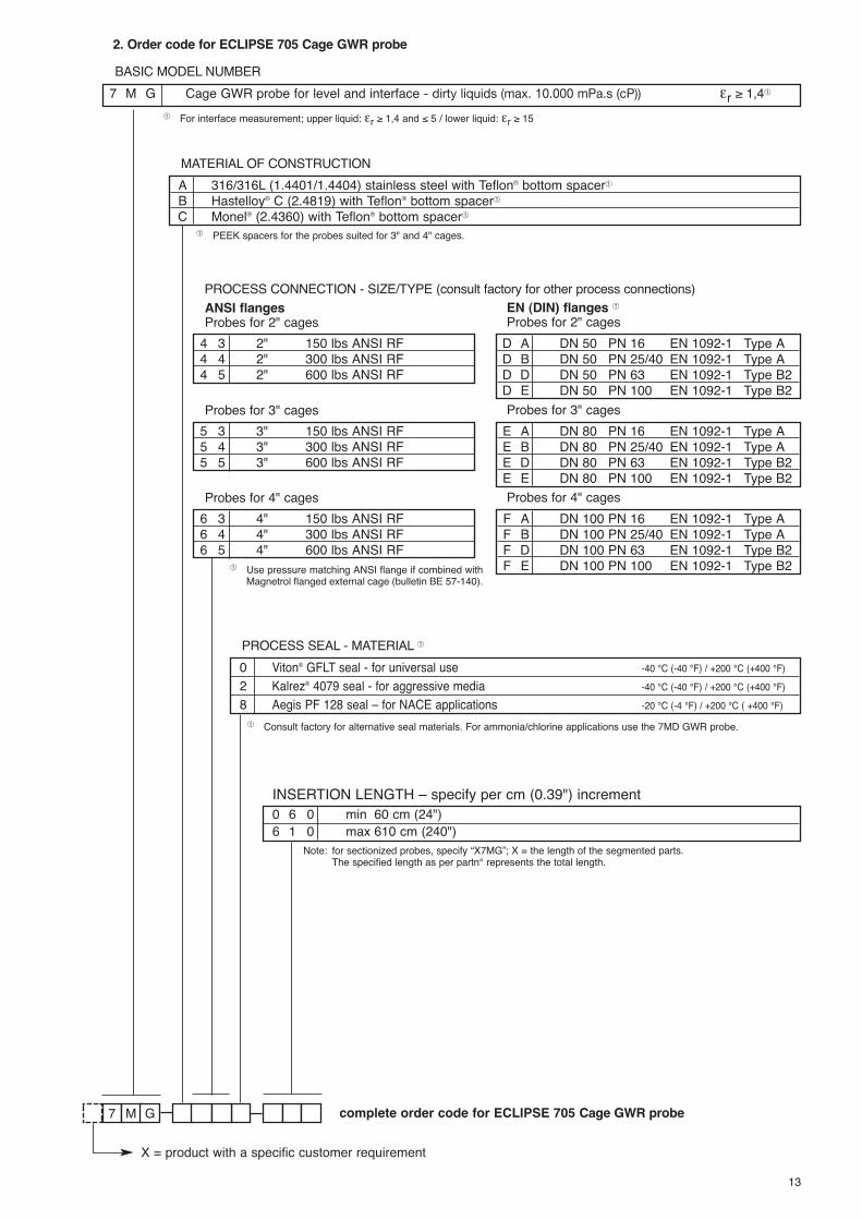
2. Order code for ECLIPSE 705 Cage GWR probe
7 M G
MATERIAL OF CONSTRUCTION
complete order code for ECLIPSE 705 Cage GWR probe
A 316/316L (1.4401/1.4404) stainless steel with Teflon® bottom spacer�
B Hastelloy® C (2.4819) with Teflon® bottom spacer�
C Monel® (2.4360) with Teflon® bottom spacer�
BASIC MODEL NUMBER7 M G Cage GWR probe for level and interface - dirty liquids (max. 10.000 mPa.s (cP)) εr ≥ 1,4�
PROCESS CONNECTION - SIZE/TYPE (consult factory for other process connections)
4 3 2" 150 lbs ANSI RF4 4 2" 300 lbs ANSI RF4 5 2" 600 lbs ANSI RF
D A DN 50 PN 16 EN 1092-1 Type AD B DN 50 PN 25/40 EN 1092-1 Type AD D DN 50 PN 63 EN 1092-1 Type B2D E DN 50 PN 100 EN 1092-1 Type B2
ANSI flangesProbes for 2" cages
EN (DIN) flanges �Probes for 2" cages
5 3 3" 150 lbs ANSI RF5 4 3" 300 lbs ANSI RF5 5 3" 600 lbs ANSI RF
E A DN 80 PN 16 EN 1092-1 Type AE B DN 80 PN 25/40 EN 1092-1 Type AE D DN 80 PN 63 EN 1092-1 Type B2E E DN 80 PN 100 EN 1092-1 Type B2
Probes for 3" cages Probes for 3" cages
6 3 4" 150 lbs ANSI RF6 4 4" 300 lbs ANSI RF6 5 4" 600 lbs ANSI RF
F A DN 100 PN 16 EN 1092-1 Type AF B DN 100 PN 25/40 EN 1092-1 Type AF D DN 100 PN 63 EN 1092-1 Type B2F E DN 100 PN 100 EN 1092-1 Type B2
Probes for 4" cages Probes for 4" cages
INSERTION LENGTH – specify per cm (0.39") increment0 6 0 min 60 cm (24")6 1 0 max 610 cm (240")
PROCESS SEAL - MATERIAL �0 Viton® GFLT seal - for universal use -40 °C (-40 °F) / +200 °C (+400 °F)2 Kalrez® 4079 seal - for aggressive media -40 °C (-40 °F) / +200 °C (+400 °F)8 Aegis PF 128 seal – for NACE applications -20 °C (-4 °F) / +200 °C ( +400 °F)
� Consult factory for alternative seal materials. For ammonia/chlorine applications use the 7MD GWR probe.
Note: for sectionized probes, specify “X7MG”; X = the length of the segmented parts.The specified length as per partn° represents the total length.
� For interface measurement; upper liquid: εr ≥ 1,4 and ≤ 5 / lower liquid: εr ≥ 15
� Use pressure matching ANSI flange if combined withMagnetrol flanged external cage (bulletin BE 57-140).
� PEEK spacers for the probes suited for 3" and 4" cages.
X = product with a specific customer requirement

14
D I M E N S I O N S i n m m ( i n c h e s )
7MSwith threaded connection
7MS with flanged connection
240 (9.45)
83(3.28)
105(4.12)
256(10.08)
102(4.00)
2 cableentries
45°
ProbeInsertionLength
156 (6.14)177 (6.97)
83(3.28)
105(4.12)
256(10.08)
102(4.00)
2 cableentries
45°
Probe InsertionLength
BSP
Probe InsertionLength NPT
Coaxial GWR Probe,End View
C
DDim. mm (inch)A 305 (12)B Ø 6,4 (0.25)C 22,5 (0.88)D 8 (0.315)Venting holes
for 7MS
AB

15
2. Order code for ECLIPSE 705 Coaxial GWR probe for saturated steam
7 8AM S
MATERIAL OF CONSTRUCTION
complete order code for ECLIPSE 705 Coaxial GWR probe for saturated steam
A 316/316L (1.4401/1.4404) stainless steel with high temperature PEEK spacers
7 M S Coaxial GWR probe for saturated steam applications, incl. steam compensation / reference target
PROCESS SEAL MATERIAL8 Steam seal (Aegis PF 128 / PEEK)
PROCESS CONNECTION - SIZE/TYPE (consult factory for other process connections)
T T 300/600 lbs Fisher (249B/259B) in carbon steel - as per dimensions of Figure 1 on page 4T U 300/600 lbs Fisher (249C) in stainless steel - as per dimensions of Figure 2 on page 4U T 300/600 lbs Masoneilan flange in carbon steel - as per dimensions of Figure 3 on page 4U U 300/600 lbs Masoneilan flange in stainless steel - as per dimensions of Figure 3 on page 4
Torque tube mating flanges �
� Always check dimensions if no ANSI/EN flanges are used.
INSERTION LENGTH – specify per cm (0.39") increment0 6 0 min 60 cm (24") with single bottom spacer4 5 0 max 450 cm (177") with spacers every 60 cm (24")
2 3 1" 150 lbs ANSI RF2 4 1" 300 lbs ANSI RF2 5 1" 600 lbs ANSI RF2 K 1" 600 lbs ANSI RJ2 L 1" 900 lbs ANSI RJ3 3 1 1/2" 150 lbs ANSI RF3 4 1 1/2" 300 lbs ANSI RF3 5 1 1/2" 600 lbs ANSI RF3 K 1 1/2" 600 lbs ANSI RJ3 M 1 1/2" 900/1500 lbs ANSI RJ3 N 1 1/2" 2500 lbs ANSI RJ4 3 2" 150 lbs ANSI RF4 4 2" 300 lbs ANSI RF4 5 2" 600 lbs ANSI RF4 K 2" 600 lbs ANSI RJ4 M 2" 900/1500 lbs ANSI RJ
4 N 2" 2500 lbs ANSI RJ5 3 3" 150 lbs ANSI RF5 4 3" 300 lbs ANSI RF5 5 3" 600 lbs ANSI RF5 K 3" 600 lbs ANSI RJ5 L 3" 900 lbs ANSI RJ5 M 3" 1500 lbs ANSI RJ5 N 3" 2500 lbs ANSI RJ6 3 4" 150 lbs ANSI RF6 4 4" 300 lbs ANSI RF6 5 4" 600 lbs ANSI RF6 K 4" 600 lbs ANSI RJ6 L 4" 900 lbs ANSI RJ6 M 4" 1500 lbs ANSI RJ6 N 4" 2500 lbs ANSI RJ
ANSI flanges
B B DN 25 PN 16/25/40 EN 1092-1 Type AB C DN 25 PN 63/100 EN 1092-1 Type B2B F DN 25 PN 160 EN 1092-1 Type B2C B DN 40 PN 16/25/40 EN 1092-1 Type AC C DN 40 PN 63/100 EN 1092-1 Type B2C F DN 40 PN 160 EN 1092-1 Type B2C G DN 40 PN 250 EN 1092-1 Type B2C H DN 40 PN 320 EN 1092-1 Type B2C J DN 40 PN 400 EN 1092-1 Type B2D A DN 50 PN 16 EN 1092-1 Type AD B DN 50 PN 25/40 EN 1092-1 Type AD D DN 50 PN 63 EN 1092-1 Type B2D E DN 50 PN 100 EN 1092-1 Type B2D F DN 50 PN 160 EN 1092-1 Type B2D G DN 50 PN 250 EN 1092-1 Type B2D H DN 50 PN 320 EN 1092-1 Type B2
D J DN 50 PN 400 EN 1092-1 Type B2E A DN 80 PN 16 EN 1092-1 Type AE B DN 80 PN 25/40 EN 1092-1 Type AE D DN 80 PN 63 EN 1092-1 Type B2E E DN 80 PN 100 EN 1092-1 Type B2E F DN 80 PN 160 EN 1092-1 Type B2E G DN 80 PN 250 EN 1092-1 Type B2E H DN 80 PN 320 EN 1092-1 Type B2E J DN 80 PN 400 EN 1092-1 Type B2F A DN 100 PN 16 EN 1092-1 Type AF B DN 100 PN 25/40 EN 1092-1 Type AF D DN 100 PN 63 EN 1092-1 Type B2F E DN 100 PN 100 EN 1092-1 Type B2F F DN 100 PN 160 EN 1092-1 Type B2F G DN 100 PN 250 EN 1092-1 Type B2F H DN 100 PN 320 EN 1092-1 Type B2F J DN 100 PN 400 EN 1092-1 Type B2
EN (DIN) flanges�
1 1 3/4" NPT 2 2 1" BSP (G 1")Threaded
X = product with a specific customer requirement
� Use pressure matching ANSI flange if combined with Magnetrol flanged external cage (bulletin BE 57-140).

16
2. Order code for Eclipse® 705 Top/Bottom GWR probe and cageIn order to re-assure that no incorrect dimensions are provided, please specify with your order the following dimensions(see drawings at bottom of page):- dimension A: top of process connection up to 20 mA range- dimension B: bottom of process connection up to 4 mA range- level range, if different from 356 mm (14").
7 AE K 0
MATERIAL OF CONSTRUCTION - wetted parts (including process connection flange when applicable)
complete order code for ECLIPSE 705 Top/Bottom GWR probe and cage
Cage and Flanges GWR probeK 316/316L (1.4401/1.4404) stainless steel 316/316L (1.4401/1.4404) stainless steelM Carbon steel
LEVEL RANGE
LIQUID TYPE / OPERATING TEMPERATURE
A 356 mm (14")
PROCESS CONNECTION - SIZE/TYPE
3 3 1 1/2" 150 lbs ANSI RF3 4 1 1/2" 300 lbs ANSI RF3 5 1 1/2" 600 lbs ANSI RF4 3 2" 150 lbs ANSI RF4 4 2" 300 lbs ANSI RF4 5 2" 600 lbs ANSI RF
ANSI flanges
BASIC MODEL NUMBERGWR probe suited for in-line external cage mounting
7 E K Top/Bottom GWR probe and cage - Overfill safe
3 1 1 1/2" NPT4 1 2" NPT
1 0 Conductive liquids (εr ≥ 10) max +315 °C (+600 °F)2 0 All liquids (εr ≥ 1,4) max +260 °C (+500 °F)
Threaded Welded
OPTIONS0 None2 Sight glass connections (sight glass not included)
DIMENSIONS in mm (inches)
Flanged 7EK
Threaded 7EK
Welded 7EK
Optional sight glassconnections
midrange
midrange
3/4" NPT-Fmidrange
midrange
A min 11/2": 102 (4.03)2": 110 (4.34)
A min 11/2": 64 (2.50)2": 86 (3.37)
A min 94 (3.69) A min. 156 (6.12)
B min 76 mm (3") B min 76 mm (3") B min 76 mm (3") B min 76 mm (3")
Max level rangein mm or inchesmin 356 (14)
max 6,1 m (240)
Max level range inmm or inchesmin 356 (14)
max 6,1 m (240)
Max level range inmm or inchesmin 356 (14)
max 6,1 m (240)
100 %
0 %
100 %
0 %
100 %
0 %
100 %
0 %
3 9 1 1/2" socket weld4 9 2" socket weld
X = product with a specific customer requirement

17
T R A N S M I T T E R S P E C I F I C AT I O N S
FUNCTIONAL/PHYSICAL
� Foundation Fieldbus™ and Profibus PA™ units.� For ATEX flameproof enclosure units use Ex d bushing material STYCAST 2057 FR.� Not applicable for Foundation Fieldbus™ and Profibus PA™ units.
Description SpecificationPower (at terminals) HART®:
- Weatherproof / ATEX flameproof enclosure / ATEX non sparking: 11 to 36 V DC- ATEX Intrinsically Safe: 11 to 28,4 V DCFoundation Fieldbus™ / Profibus PA™:- Weatherproof / ATEX flameproof enclosure / ATEX FNICO: 9 to 32 V DC- ATEX FISCO: 9 to 17,5 V DC
Output 4-20 mA with HART®, 3,8 mA to 20,5 mA useable (meets NAMUR NE 43),Foundation Fieldbus™ H1 or Profibus PA™ H1
Span 15 cm to 610 cm (6" to 240") depending on selected probeResolution Analog: 0,01 mA
Display: 0,1 (cm or inch)Loop Resistance 630 Ω @ 20,5 mA - 24 V DCDamping Adjustable 0-10 sDiagnostic Alarm Adjustable 3,6 mA, 22 mA, HOLD last outputUser Interface HART® communicator, AMS® or PACTware™, Foundation Fieldbus™, Profibus PA™
and/or 3-button keypad Display 2-line x 8-character LCDMenu Language English/Spanish/French/German (Foundation Fieldbus™, Profibus PA™: English)Housing Material IP 66/Aluminium A356T6 (< 0.20 % copper) or stainless steelApprovals ATEX II 3 (1) G EEx nA [ia] IIC T6, non sparking (probe can be used in flammable liquids)
ATEX II 3 (1) G EEx nA [nL][ia] IIC T6, FNICO – non incendive� (probe can be used inflammable liquids)ATEX II 1 G Ex ia IIC T4 Ga, intrinsically safeATEX II 1 G Ex ia IIC T4 Ga, FISCO – intrinsically safe�
ATEX II 1/2 G Ex d[ia Ga] IIC T6 Gb�
ATEX II 1/2 D Ex t[ia Da] IIIC T85°C Db IP66�
IEC Ex d[ia Ga] IIC T6 GbIEC Ex t[ia Da] IIIC T85°C Db IP66EN 12952-11 and EN 12953-9 CE approved for steam drums as primary level safetydeviceTÜV – WHG § 63, VLAREM II 5.17-7LRS – Lloyds Register of Shipping (marine applications)Other approvals are available, consult factory for more details
SIL�
(Safety Integrity Level)Standard electronics
Functional safety to SIL 1 as 1oo1 / SIL 2 as 1oo2 in accordance to IEC 61508 – SFF of85,4 % – full FMEDA reports and declaration sheets available at request
Enhanced electronics
Functional safety to SIL 2 as 1oo1 in accordance to IEC 61508 – SFF of 91 %– full FMEDA reports and declaration sheets available at request. Certified for use in SIL 3 loops.
Electrical Data Ui = 28,4 V, li = 120 mA, Pi = 0,84 W (HART®)Ui = 17,5 V, li = 380 mA, Pi = 5,32 W (Foundation Fieldbus™ / Profibus PA™)
Equivalent Data Ci = 2,2 nF, Li = 3 µH (HART®)Ci = 3 nF, Li = 3 µH (Foundation Fieldbus™ / Profibus PA™)
Shock/Vibration Class ANSI/ISA-S71.03 Class SA1 (Shock), ANSI/ISA-S71.03 Class VC2 (Vibration)Net weight Cast aluminium 2,7 kg (6.0 lbs) – transmitter head / electronics only
Stainless steel 5,7 kg (12.6 lbs) – transmitter head / electronics onlyOverall Dimensions H 214 mm (8.43") x W 111 mm (4.38") x D 188 mm (7.40")Foundation Fieldbus™specifications
ITK Version 5.0H1 Device Class Link Master (LAS) – selectable ON/OFFH1 Profile Class 31PS, 32LFunction Blocks 1 x RB, 4 x AI, 1 x TB and 1 x PIDQuiescent current draw 15 mAExecution time AI = 15 ms, PID = 40 msCFF files Downloads available from Host system supplier or www.fieldbus.org
Profibus PA specifications
Device revision 0x01Digital communicationprotocols
Version 3.0 MBP (31.25 kbits/sec)
Function Blocks 1 x PB, 4 x Al blocks, 1 x TBQuiescent current draw 15 mAExecution time 15 msGSD files Dowloads available from www.profibus.com or Magnetrol.com

PERFORMANCE
� May degrade for 7MD/7ML probe or with fixed threshold.� Accuracy may degrade slightly < 2,5 m (8')� Transition Zone (zone with reduced accuracy) is dielectric dependent; εr = dielectric permitivity. It is recommended to set 4-20 mA signal outside transition
zones.� See graphs at page 21 and 22.
Description SpecificationReference Conditions with a 1,8 m (72")coaxial type GWR probe
Reflection from liquid, with dielectric in center of selected range, at +20 °C (70 °F) withCFD threshold�
Linearity < 0,1 % of probe length or 2,5 mm (0.1"), whichever is greaterAccuracy Level measurement < 0,1 % of probe length or 2,5 mm (0.1"), whichever is greater
Interface measurement ± 25 mm (1")Resolution ± 2,5 mm (0.1")Repeatability < 2,5 mm (0.1")Hysteresis < 2,5 mm (0.1")Response Time < 1 secondWarm-up Time < 5 secondsAmbient Temp. -40 °C to +80 °C (-40 °F to +175 °F) – blind transmitter
-20 °C to +70 °C (-5 °F to +160 °F) – with digital display-40 °C to +70 °C (-40 °F to +160 °F) – for Ex ia and Ex d[ia] with blind transmitter-20 °C to +70 °C (-5 °F to +160 °F) – for Ex ia and Ex d[ia] with digital display
Process Dielectric Effect < 7,5 mm (0.3") within selected rangeOperating Temp. Effect Approx. +0,02 % of probe length/°C for probes ≥ 2,5 m (8')�Humidity 0-99 %, non-condensingElectromagnetic Compatibility Meets CE requirements (EN 61326: 1997 + A1 + A2) and NAMUR NE 21
P R O B E S P E C I F I C AT I O N SDescription 7MR/7MM: overfill protection coaxial probeMaterials Probe 316/316L (1.4401/1.4404), Hastelloy® C (2.4819) or Monel® (2.4360)
Process seal Teflon® with Viton® GFLT, Aegis PF 128 or Kalrez® 4079 (consult factory for alternatives)Spacers Teflon®
Probe diameter Stainless steel Inside rod 16 mm (0.63") – outer tube 45 mm (1.75")Hast. C / Monel® Inside rod 16 mm (0.63") – outer tube 49 mm (1.93")
Mounting External cage and/or in-tank mountingProcess Connection Flanged: various ANSI, EN (DIN) or torque tube mating flangesProbe length From 60 cm to 610 cm (24" to 240")Transition Zone� Top 0 mm (0")
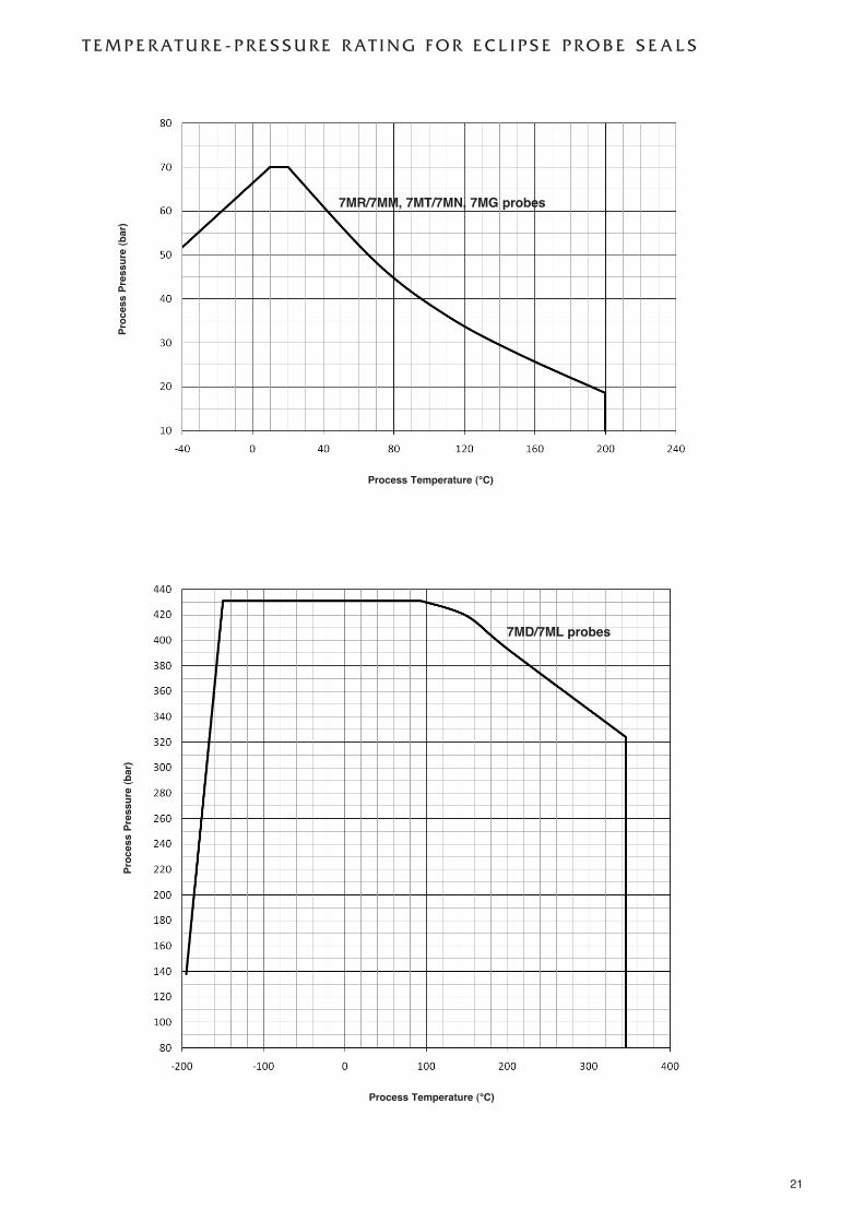
Bottom εr: 1,4 = 150 mm (6")/εr: 80 = 25 mm (1")Process Temp.� Max +200 °C @ 18,6 bar (+400 °F @ 270 psi)
Min -40 °C @ 51,7 bar (-40 °F @ 750 psi)Max. Process Pressure� 70 bar @ +20 °C (1000 psi @ +70 °F)Max. Viscosity 2000 mPa.s (cP)Dielectric Range 1,4 to 100Vacuum Service Negative pressure but not hermetic sealMedia coating In case of media coating, select 7MM probe
Description 7MD/7ML: high pressure / high temperature GWR probeMaterials Probe 316/316L (1.4401/1.4404), Hastelloy® C (2.4819) or Monel® (2.4360)
Process seal Borosilicate / Inconel® X-750Spacers PEEK
Probe diameter Stainless steel Inside rod 16 mm (0.63") – outer tube 45 mm (1.75")Hast. C / Monel® Inside rod 16 mm (0.63") – outer tube 49 mm (1.93")
Mounting External cage and/or in-tank mountingProcess Connection Flanged: various ANSI, EN (DIN) or torque tube mating flangesProbe length From 60 cm to 610 cm (24" to 240")Transition Zone� Top 0 mm (0")
Bottom εr: 1,4 = 150 mm (6") / εr: 80 = 25 mm (1")Process Temp.� Max +345 °C @ 324 bar (+650 °F @ 4700 psi)
Min -196 °C @ 138 bar (-320 °F @ 2000 psi)Max. Process Pressure� 431 bar @ +20 °C (6250 psi @ +70 °F)Max. Viscosity 2000 mPa.s (cP)Dielectric Range Level Probes ≤ 2,5 m: εr ≥ 1,4 with single bottom spacer
Probes > 2,5 m: εr ≥ 1,7Interface Upper liquid: εr ≥ 1,4 or 1,7 (see above) and ≤ 5
Lower liquid: εr ≥ 15Vacuum service Full vacuum (Helium leak < 10-8 cc/s @ 1 atmosphere vacuum)Media coating In case of media coating, select 7ML probe
18

19
Description 7MT/7MN: interface GWR probeMaterials Probe 316/316L (1.4401/1.4404), Hastelloy® C (2.4819) or Monel® (2.4360)
Process seal Teflon® with Viton® GFLT, Aegis PF 128 or Kalrez® 4079 (consult factory for alternatives)Spacers Teflon®
Probe diameter Stainless steel Inside rod 16 mm (0.63") – outer tube 45 mm (1.75")Hast. C / Monel® Inside rod 16 mm (0.63") – outer tube 49 mm (1.93")
Mounting External cage and/or in-tank mountingProcess Connection Flanged: various ANSI, EN (DIN) or torque tube mating flangesProbe length From 60 cm to 610 cm (24" to 240")Transition Zone� Top 0 mm (0")
Bottom εr: 1,4 = 150 mm (6")/εr: 80 = 50 mm (2")Process Temp.� Max +200 °C @ 18,6 bar (+400 °F @ 270 psi)
Min -40 °C @ 51,7 bar (-40 °F @ 750 psi)Max. Process Pressure� 70 bar @ +20 °C (1000 psi @ +70 °F)Max. Viscosity 2000 mPa.s (cP)Dielectric Range Upper liquid: εr ≥ 1,4 and ≤ 5
Lower liquid: εr ≥ 15Vacuum service Negative pressure but not hermetic sealMedia coating In case of media coating, select 7MN probe
Description 7MS: saturated steam GWR probeMaterials Probe 316/316L (1.4401/1.4404)
Process seal High Temp PEEK with Aegis PF 128Spacers High Temp PEEK
Probe diameter Inside rod 8 mm (0.315) – outer tube 22,5 mm (0,88")Mounting External cage and/or in-tank mountingProcess Connection Threaded: 3/4" NPT or 1" BSP (G 1")
Flanged: various ANSI, EN (DIN) or torque tube mating flangesProbe length From 60 cm to 450 cm (24" to 177")Transition Zone� Top 200 mm (8"); consult factory for overfill applications
Bottom εr ≥ 10 = 25 mm (1")Process Temp.� Max +345 °C @ 155 bar (+650 °F @ 2250 psi)
Min -15 °C @ 207 bar (0 °F @ 3000 psi)Max. Process Pressure� 155 bar @ +345 °C (2250 psi @ +650 °F)Max. Viscosity 500 mPa.s (cP)Dielectric Range 10 to 100Vacuum service Negative pressure but not hermetic sealMedia coating Not applicable
� Transition Zone (zone with reduced accuracy) is dielectric dependent; εr = dielectric permitivity. It is recommended to set 4-20 mA signal outside transition zones.
� See graphs at page 21 and 22.

20
Description 7EK: Top/Bottom GWR probeεεr ≥ 1,4 - max +260 °C
7EK: Top/Bottom GWR probeεεr ≥ 10 - max +315 °C
Materials Probe 316/316L (1.4401/1.4404)Process seal PEEK and TFE with Aegis PF 128 PEEK and Alumina with Aegis PF 128Bottom spacer TFE PEEK
Probe diameter Inside tube: max 22,5 mm (0.88")Cage 2" - Sch 80 Top/Bottom cageProcess Connection Threaded: 1 1/2" NPT or 2" NPT
Welded: 1 1/2" or 2" socket weldFlanged: Various ANSI, EN (DIN) or torque tube mating flanges
Measuring range min 356 mm (14") Std. – max 6,1 m (240")Process Temp.� Max +260 °C @ 117 bar (+500 °F @ 1700 psi) +315 °C @ 109 bar (+600 °F @ 1585 psi)
Min -15 °C @ 117 bar (0 °F @ 1700 psi)Max. Process Pressure� 117 bar @ -15 °C (1700 psi @ +0 °F)Max. Viscosity 10.000 mPa.s (cP)Dielectric Range (level only) 1,4 to 100 - Non conductive and conductive
media10 to 100 - Conductive media
Vacuum service Negative pressure but not hermetic seal
Description 7MG: cage GWR probeMaterials Probe 316/316L (1.4401/1.4404), Hastelloy® C (2.4819) or Monel® (2.4360)
Process seal Teflon® with Viton® GFLT, Aegis PF 128 or Kalrez® 4079 (consult factory for alternatives)Bottom spacer 2" cage: Teflon®; 3" and 4" cage: PEEK
Probe diameter 2" cage 13 mm (0.50")3" cage 19 mm (0.75")4" cage 25 mm (1")
Mounting In a 2", 3" or 4" cage / schedule pipe stillwell or bridleProcess Connection Flanged: various ANSI or EN (DIN) flangesProbe length From 60 cm to 610 cm (24" to 240")Transition Zone� Top 0 mm (0")
Bottom εr: 1,4 = 150 mm (6")/εr: 80 = 50 mm (2")Process Temp.� Max +200 °C @ 18,6 bar (+400 °F @ 270 psi)
Min -40 °C @ 51,7 bar (-40 °F @ 750 psi)Max. Process Pressure� 70 bar @ +20 °C (1000 psi @ +70 °F)Max. Viscosity 10.000 mPa.s (cP)Dielectric Range Level εr ≥ 1,4
Interface Upper liquid: εr ≥ 1,4 and ≤ 5Lower liquid: εr ≥ 15
Vacuum Service Negative pressure but not hermetic sealMedia coating Max error of 10 % of coated length. % Error is related to dielectric of medium, thickness of
coating and coated probe length above level.
� Transition Zone (zone with reduced accuracy) is dielectric dependent; εr = dielectric permitivity. It is recommended to set 4-20 mA signal outside transition zones.
� See graphs at page 21 and 22.
21
T E M P E R AT U R E - P R E S S U R E R AT I N G F O R E C L I P S E P R O B E S E A L S
Process Temperature (°C)
Process Pressure (b
ar)
Process Temperature (°C)
Process Pressure (b
ar)
7MR/7MM, 7MT/7MN, 7MG probes
7MD/7ML probes

22
Process Temperature (°C)
Process Pressure (b
ar)
Process Temperature (°C)
Process Pressure (b
ar)
7MS probes
7EK probes for max +260 °C7EK probes for max +315 °C and conductive liquids only

23
QUALITY ASSURANCE - ISO 9001:2008THE QUALITY ASSURANCE SYSTEM IN PLACE AT MAGNETROL GUARANTEES THE HIGHEST LEVEL OF QUALITY DURING THE DESIGN,THE CONSTRUCTION AND THE SERVICE OF CONTROLS.OUR QUALITY ASSURANCE SYSTEM IS APPROVED AND CERTIFIED TO ISO 9001:2008 AND OUR TOTAL COMPANY IS COMMITTED TOPROVIDING FULL CUSTOMER SATISFACTION BOTH IN QUALITY PRODUCTS AND QUALITY SERVICE.
PRODUCT WARRANTYALL MAGNETROL ELECTRONIC AND ULTRASONIC LEVEL CONTROLS ARE WARRANTED FREE OF DEFECTS IN MATERIALS AND WORK-
MANSHIP FOR ONE FULL YEAR FROM THE DATE OF ORIGINAL FACTORY SHIPMENT. IF RETURNED WITHIN THE WARRANTY PERIOD; AND, UPON FACTORY INSPEC-TION OF THE CONTROL, THE CAUSE OF THE CLAIM IS DETERMINED TO BE COVERED UNDER THE WARRANTY; THEN, MAGNETROL INTERNATIONAL WILL REPAIR ORREPLACE THE CONTROL AT NO COST TO THE PURCHASER (OR OWNER) OTHER THAN TRANSPORTATION. MAGNETROL SHALL NOT BE LIABLE FOR MISAPPLICATION, LABOR CLAIMS, DIRECT OR CONSEQUENTIAL DAMAGE OR EXPENSE ARISING FROM THE INSTALLATIONOR USE OF THE EQUIPMENT. THERE ARE NO OTHER WARRANTIES EXPRESSED OR IMPLIED, EXCEPT, SPECIAL WRITTEN WARRANTIES COVERING SOME MAGNETROLPRODUCTS.
:2008
BENELUX Heikensstraat 6, 9240 Zele, België -BelgiqueFRANCE Tel. +32 (0)52.45.11.11 • Fax. +32 (0)52.45.09.93 • E-Mail: [email protected] Alte Ziegelei 2-4, D-51491 Overath
Tel. +49 (0)2204 / 9536-0 • Fax. +49 (0)2204 / 9536-53 • E-Mail: [email protected] C-20 Community Centre, Janakpuri, New Delhi - 110 058
Tel. +91 (11) 41661840 • Fax +91 (11) 41661843 • E-Mail: [email protected] Via Arese 12, I-20159 Milano
Tel. +39 02 607.22.98 • Fax. +39 02 668.66.52 • E-Mail: [email protected]
U.A.E. DAFZA Office 5EA 722 • PO Box 293671 • DubaiTel. +971-4-6091735 • Fax +971-4-6091736 • E-Mail: [email protected]
RUSSIA 198095 Saint-Petersburg, Marshala Govorova street, house 35A, office 532Tel. +7-812.702.70.87 • E-Mail: [email protected]
UNITED Unit 1 Regent Business Centre, Jubilee Road Burgess Hill West Sussex RH 15 9TLKINGDOM Tel. +44 (0)1444 871313 • Fax +44 (0)1444 871317 • E-Mail: [email protected]
www.magnetrol.com
BULLETIN N°: BE 57-102.2EFFECTIVE: JULY 2012SUPERSEDES: November 2011UNDER RESERVE OF MODIFICATIONS
OUR NEAREST REPRESENTATIVE