eclipse enhanced 705 sales literature be57-101 · 3 in order to match the proper eclipse...
TRANSCRIPT

Guided Wave RadarLevel Transmitter
Measures real «LEVEL, VOLUME, INTERFACE»
www.eclipse.magnetrol.com
D E S C R I P T I O NThe Eclipse 705 Transmitter is a loop-powered, 24 V DCliquid-level transmitter based on the revolutionary GuidedWave Radar (GWR) technology. Encompassing a numberof significant engineering accomplishments, this leadingedge level transmitter is designed to provide measurementperformance well beyond that of many traditional technolo-gies, as well as “through-air” radars.The innovative enclosure is a first in the industry, orientingdual compartments (wiring and electronics) in the sameplane, and angled to maximize ease of wiring, configuration,set-up and data display.This single transmitter can be used with all probe types andoffers enhanced reliability, for use in SIL 2 loops as 1oo1.
F E AT U R E S* “REAL LEVEL”, measurement not affected by media vari-
ables eg. dielectrics, pressure, density, pH, viscosity, ...* Easy bench configuration - no need for level simulation.* Two-wire, intrinsically safe loop powered level transmitter.* 20-point custom strapping table for volumetric output.* 360° rotatable housing can be dismantled without depres-
surizing the vessel via “Quick connect/disconnect” probecoupling.
* Two-line, 8-character LCD and 3-button keypad.* Probe designs: up to +430 °C / 430 bar (+800 °F / 6250 psi).* Saturated steam applications up to 155 bar @ +345 °C
(2250 psi @ +650 °F).* Cryogenic applications down to -196 °C (-320 °F).* Integral or remote electronics.* Suited for SIL 1 or SIL 2 Loops (full FMEDA report avail-
able).
A P P L I C AT I O N SMEDIA: Liquids or slurries; hydrocarbons to water-basedmedia (dielectric 1,4 - 100) and solids (dielectric 1,9 - 100).VESSELS: Most process or storage vessels up to ratedprobe temperature and pressure.CONDITIONS: All level measurement and control applicationsincluding process conditions exhibiting visible vapors, foam,surface agitation, bubbling or boiling, high fill/empty rates, lowlevel and varying dielectric media or specific gravity.
Ask for your free copy of the Eclipse® 705 performance reportby WIB/Evaluation International (SIREP)/EXERA.
Worldwide level and flow solutions
A G E N C Y A P P R O VA L S
Agency ApprovalsATEX II 3 (1) G EEx nA [ia] IIC T6, non sparking �
II 3 (1) G EEx nA [nL] [ia] IIC T6, FNICO – non incendive ��
II 1 G EEx ia IIC T4, intrinsically safeII 1 G EEx ia IIC T4, FISCO – intrinsically safe�
II 1 / 2 G D EEx d[ia] IIC T6, explosion proofLloyds Primary level safety device for steamdrums
conform to- EN 12952-11 (water tube boilers)- EN 12953-9 (shell boilers)
TÜV WHG § 19, overfill preventionAIB VLAREM II – 5.17.7FM/CSA� Non Incendive / Intrinsically safe / Explosion proofLRS Lloyds Register of Shipping (marine applications)RosTECH/FSTS Russian Authorisation StandardsGOST-K/GGTN-K
� Probe is intrinsically safe to ATEX II 1 G EEx ia IIC T6 and can be usedin zone 0, on flammable liquids.
� Foundation Fieldbus™ and Profibus PA units are FNICO (non sparking),FISCO (intrinsically safe) and ATEX – FM/CSA explosion proof approved.
® 705
SAFETY INTEGRITYLEVEL
Eclipse withtwin rodGWR probeup to 6,1 m
Eclipse withsingle cableGWR probeup to 22 m
Eclipse withcoaxial typeGWR probeup to 6,1 m
2
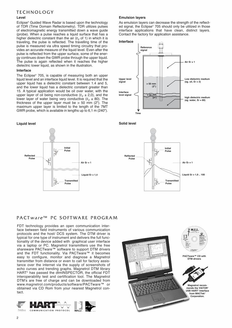
T E C H N O L O G YLevelEclipse® Guided Wave Radar is based upon the technologyof TDR (Time Domain Reflectometry). TDR utilizes pulsesof electromagnetic energy transmitted down a wave guide(probe). When a pulse reaches a liquid surface that has ahigher dielectric constant than the air (εr of 1) in which it istraveling, the pulse is reflected. The travelling time of thepulse is measured via ultra speed timing circuitry that pro-vides an accurate measure of the liquid level. Even after thepulse is reflected from the upper surface, some of the ener-gy continues down the GWR probe through the upper liquid.The pulse is again reflected when it reaches the higherdielectric lower liquid, as shown in the illustration.InterfaceThe Eclipse® 705, is capable of measuring both an upperliquid level and an interface liquid level. It is required that theupper liquid has a dielectric constant between 1.4 and 5,and the lower liquid has a dielectric constant greater than15. A typical application would be oil over water, with theupper layer of oil being non-conductive (εr ± 2,0), and thelower layer of water being very conductive (εr ± 80). Thethickness of the upper layer must be > 50 mm (2"). Themaximum upper layer is limited to the length of the 7MTGWR probe, which is available in lengths up to 6,1 m (240").
Emulsion layersAs emulsion layers can decrease the strength of the reflect-ed signal, the Eclipse® 705 should only be utilized in thoseinterface applications that have clean, distinct layers.Contact the factory for application assistance.
Air εεr = 1
Reference signal
Time
Upper levelsignal
> 50 mm (2")
< 50 mm (2")
Interface level signal
Interface
Liquid level Solid level
Low dielectric medium(eg. oil, εεr = 2)
high dielectric medium(eg. water, εεr = 80)
FDT technology provides an open communication inter-face between field instruments of various communicationprotocols and the host/ DCS system. The DTM driver istypical for one type of instrument and delivers the full func-tionality of the device added with graphical user interfacevia a laptop or PC. Magnetrol transmitters use the freeshareware PACTware™ software to support DTM driversand the FDT functionality. Via PACTware™ it becomeseasy to configure, monitor and diagnose a Magnetroltransmitter from distance or even to call for factory assis-tance over the internet via the supply of screenshots ofecho curves and trending graphs. Magnetrol DTM libraryHART® has passed the dtmINSPECTOR, the official FDTinteroperability test and certification tool. The MagnetrolDTMʼs are free of charge and can be downloaded fromwww.magnetrol.com/products/software/PACTware™ orobtained via CD Rom from your nearest Magnetrol con-tact.
PA C T w a r e ™ P C S O F T WA R E P R O G R A M
ReflectedPulse
InitialPulse
Air εεr = 1
Liquid εεr > 1,4
TransmittedPulse
ReflectedPulse
InitialPulse
Air εεr = 1
Liquid εεr > 1,9 .. 100
TransmittedPulse
PACTware™ CD withDTM drivers
Magnetrol recom-mends the VIATOR®
USB HART® Interfacefrom MACTek®Corporation.

3
In order to match the proper Eclipse transmitter with the proper external cage, consider the following:- Type of application – use the applicable GWR probe, see page 5.- Overfill proof: Overfilling occurs when the level rises above the max level – radar based equipment may provide erro-
neous output in this zone unless an adapted design is used. GWR probes without top transition zone (e.g. 7MR, 7MD,7MT) are always safe to use – only in cases where the application demands for a different probe type, other selectionsshould be considered and the recommended precautions followed.
- Min cage size:- coaxial type: min 2"/DN 50- twin rod type: min 3"/DN 80- single rod type: consult factory.
Measuring range:min 300 mm (11.81")max 5700 mm (224")
E
Probe Insertion Length =+ measuring range + FE
20 mA / 100 %
4 mA / 0 %min 25 mm (1")
Body connection
F
P
Eclipse® has proven to be the perfect replacement for exist-ing torque tube transmitters. In hundreds of applicationsaround the globe, customers have found Eclipse® GuidedWave Radar superior to torque tube transmitters:• Cost:
A new Eclipse® costs only slightly more than rebuilding anaging torque tube.
• Installation:No field calibration is necessary; it can be configured inminutes with no level movement. Pre-configuration fromfactory is free of charge.
• Performance:Eclipse® is not affected by changes in specific gravity ordielectric.
• Ease of replacement:Proprietary flanges are offered so existing chamber/cages can be used.
Before After
R E P L A C E M E N T O F D I S P L A C E R T R A N S M I T T E R
Manufacturer Type Process connection Displacer lengthinches (mm)
Probe length�
mm (inches)
Magnetrol® EZ & PNModulevel® ANSI/DIN flange ≥ 14" (356) Displacer + 178 (7)
Masoneilan® Series 1200Proprietary flange ≥ 14" (356) Displacer + 203 (8)ANSI/DIN flange ≥ 16" (406) Displacer + 203 (8)
Fisher® series2300 & 2500
249B, 259B,249C cages Proprietary flange ≥ 14" (356) Displacer + 254 (10)
other cages ANSI flange ≥ 14" (356) consult factoryEckhardt® Series 134,144 ANSI/DIN flange ≥ 14" (356) consult factory
Tokyo Keiso® FST-3000ANSI/DIN flange H = 11.8" (300) Displacer + 229 (9)ANSI/DIN flange ≥ H = 19.7" (500) Displacer + 229 (9)
Indicative probe length for replacing displacer transmittersBelow table helps to define the GWR probe length based upon the length of the most common displacer transmitters. Consultthe selection guide on the next page.
� Round down resulting calculation to the nearest cm.

4
Figure 1 Figure 2 Figure 3
In addition to Magnetrolʼs Torque Tube Cage Flangeoptions, the Eclipse® 705 transmitter and 7EK GWRprobe/cage can also be used in replacing existingTop/Bottom and Top/Side torque tube installations.After removal of the existing torque tube cage assembly(controller, displacer and cage), Eclipse Guided WaveRadar may then be installed directly in its place. Severalmodels are available for some of the major torque tube dis-placer transmitter manufacturers. Because the Model 7EKprobe/cage mounting dimensions and measuring rangesmatch the original manufacturerʼs specification, no re-pip-ing is necessary.
Before After
A U R O R A ™Aurora® is the innovative combination of the Eclipse®
Guided Wave Radar and a Magnetic Level Indicator(MLI). The MLI indicator rail offers the Eclipse ahighly visible level indication that may obsolete theneed for local indicators. The integration of thesetwo independent technologies provides an excellentredundancy in one integrated design. With Aurora® itis even possible to plan maintenance ahead.Maintenance becomes needed when build up in aninstallation has surpassed the allowable limit. Buildup on the float inside the MLI cage will force it to sinkdeeper in the liquid while the measurement of theEclipse will not see any build up until its both leadelements are completely clugged. In this way, thefloat will indicate a lower level versus the real levelmeasured by the Eclipse. The degree of deviationbetween both read outs is a worthwhile tool to deter-mine the real need for maintenance. For more details – consult bulletin 57-138.
C A G E SEclipse can be built into cages as small asDN 50 / 2". When a new cage is needed, it canbe ordered together with the Eclipse. Magnetrolhas a long tradition in offering cost effectivecages. Magnetrol cages comply with PED regu-lations and are available with a wide variety ofoptions.
Measuring span 30-610 cm (12-240") �
Materials of construction Carbon steel or 316 (1.4401) stainless steel
Process connection sizes 3/4", 1", 1 1/2", 2"Process connection ratings 150#-2500# ANSIConfigurations Side-Side and Side-BottomProcess pressures Up to 430 bar (6250 psig) �
Process temperatures Up to +430 °C (+800 °F) �
� Limitations are defined per selected GWR probe.
For more details – consult bulletin 57-140.
P R O P R I E TA R Y F L A N G E S
Ø 229(9.0)
32(1.125)
Fisher 249B/259B (600 lbs), carbon steel
133(5.23) 6
(.22)
Ø 184(7.25)
Ø 22(.875)
45°
Ø 143(5.625)
29(1.125)
Fisher 249C (600 lbs), 316 stainless steel
86(3.375) 5
(.188)
Ø 121(4.750)
Ø 11(.438)
45°
Ø 191(7.50)
29(1.125)
Masoneilan (600 lbs), 316 carbon steel
102(4.00) 6
(.25)
Ø 149(5.875)
Ø 22(.875)
45°
R E P L A C E M E N T O F T O P / B O T T O MC A G E S
H Y G I E N I C E C L I P S E 7 0 5Eclipse 705 is available with a deep drawnhousing and a 0,4 µm (RA 15) finished singlerod GWR probe for use in ultra clean environ-ments.For more details – consult bulletin 57-110

S E L E C T I O N G U I D E
5
COAXIAL TYPE GWR PROBE
signal propagation
TWIN ROD/CABLE TYPE GWR PROBE
signal propagation
Dielectric limit
COAXIAL TYPE GWR probes - max viscosity 500 cP (I.D. 3/4") – 2000 cP (I.D. 1 3/4"). Consult bulletin 57-102
GWR ProbeTemperature limitsApplication
εr 1,4 - 100 7MR/7MM-40 °C up to +200 °C max 70 bar Yes Yes NoLevel
Twin rod/cable GWR probes - max 1500 cP
εr 1,9 - 100 7MB-40 °C up to +200 °C max 50 bar Yes No YesLiquids - rod
Single rod/cable GWR probes - max 10.000 cP
εr 1,9 - 100� 7MF-40 °C up to +150 °C max 70 bar Yes No YesLiquids - rod
εr 1,9 - 100� 7M1-40 °C up to +150 °C max 70 bar Yes No YesLiquids - cable
εr 4 - 100 7M2Ambient Atmospheric Yes No NASolids - cable
εr 1,9 - 100� 7MJ-40 °C up to +315 °C max 207 bar Yes No YesHigh temp / high pressure
εr 1,9 - 100 7M7-40 °C up to +200 °C max 50 bar Yes No NoLiquids: level / interface - cable
εr 1,9 - 100 7M5Ambient Atmospheric Yes No NASolids - cable
εr 1,4 - 100� 7MD/7ML-196 °C up to +430 °C max 430 bar Full Yes NoHigh temp / High pressureInterface
εr 10 - 100 7MSup to +345 °C max 155 bar Yes No NoSaturated steam
εr 1,4 - 100 7MT/7MN-40 °C up to +200 °C max 70 bar Yes Yes NoLevel / Interface
ApplicationsPressure Vacuum Overfill Foam
� safe �
� Each Eclipse probe can be used for vacuum service (negative pressure) but only the Borosilicate GWR probes (7MD/7ML) are suited for full vacuum condi-tions (Helium leak < 10-8 cc/s @ 1 bar abs.)
� Eclipse is ideally suited to be used on foaming applications but in specific conditions where dense foam can enter/hydrate in the stilling well, coaxial GWRprobes are not recommended.
� Depending spacer material. See model selection 7MD/7ML GWR probe.� For media with εr 1.9 up to 10, GWR probe must be mounted in between 75 mm and 150 mm (3"-6") away from the metal tank wall or in a metal cage /
stillwell.
end viewend view
SINGLE ROD/CABLE TYPE
signal propagation
6
E X P E D I T E S H I P P L A N ( E S P )Several Eclipse Guided Wave Radar Transmitters are available for quick shipment, within max. 4 weeks after factory receiptof purchase order, through the Expedite Ship Plan (ESP).Models covered by ESP service are conveniently colour coded in the selection data charts.To take advantage of ESP, simply match the colour coded model number codes (standard dimensions apply).ESP service may not apply to orders of ten units or more. Contact your local representative for lead times on larger volumeorders, as well as other products and options.
S E L E C T I O N D ATAA complete measuring system consists of:1.Eclipse transmitter head/electronics2.Eclipse 705 GWR probe3.Free of charge: Magnetrol master C.D. with Eclipse 705 DTM (PACTware™). Order code: 090-BE59-200 (included in each
order).4.OPTION: - TFE spacer for single rod metal GWR probes; order code: 089-9114-001 (7MF-A), 089-9114-002 (7MF-B),
- 089-9114-003 (7MF-C)- PEEK spacer for single rod 7MJ GWR probe; order code: 089-9114-005 (7MJ-A), 089-9114-006 (7MJ-B), - 089-9114-007 (7MJ-C)- Additional weight for 7M1 GWR probe; order code: 089-9120-001- Additional weight for 7M7 GWR probe; order code: 089-9121-001- Additional weight for 7M2 GWR probe; order code: 004-8778-001 (requires 2 x 010-1731-001: cable clamps)- Additional weight for 7M5 GWR probe; order code: 004-8778-002 (requires 2 x 010-1731-001: cable clamps)
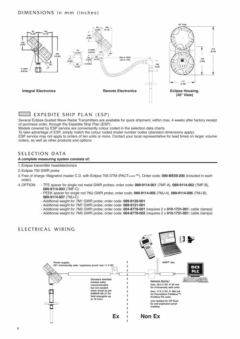
D I M E N S I O N S i n m m ( i n c h e s )
83(3.28)
105(4.12)
108(4.25)
95(3.75)76
(3.00)
89(3.50)
70(2.75)
2 holes
2 cableentries
51(2.00)
840 or 3650(33 or 144)
102(4.00)
214 (8.43)
126 (4.94)
111(4.38)
45° View
45°
Eclipse Housing,(45° View)
Remote ElectronicsIntegral Electronics
E L E C T R I C A L W I R I N G
0 % 100 %
Power supply: GP / intrinsically safe / explosion proof: min 11 V DC
Standard shielded twisted cable(recommendedbut not neededwhen wired as perNAMUR NE 21 forfield strenghts upto 10 V/m).
Galvanic Barrier:max: 28,4 V DC @ 94 mAfor intrinsically safe unitsmax: 17,5 V DC @ 380 mAfor Foundation Fieldbus™/Profibus PA units (not needed for GP DustEx and explosion proofmodels).
Ex Non Ex
83(3.28)
105(4.12)
256(10.08)
102(4.00)
2 cableentries
45°
HART® key

7
1. Order code for ECLIPSE 705 transmitter head/electronics
7 50 5
POWER
complete order code for ECLIPSE 705 transmitter head/electronics
5 24 V DC, two wire loop powered
BASIC MODEL NUMBER7 0 5 Eclipse 705 guided wave radar transmitter
SIGNAL OUTPUT AND ELECTRONICS
CABLE ENTRY1 M20 x 1.5 (2 entries - one plugged)0 3/4" NPT (2 entries - one plugged)
ACCESSORIESA Digital display and keypad0 Blind transmitter (no display/keypad)
1 0 4-20 mA with Hart – standard electronics (SFF of 85.4%)1 A 4-20 mA with Hart – SIL enhanced electronics (SFF of 91%)2 0 Foundation Fieldbus™ communication3 0 Profibus PA™ communication
MOUNTING / HOUSING MATERIAL / CLASSIFICATION (Consult factory for FM/CSA approvals)
1 1 Weatherproof area (& I.S. FM/CSA)A 1 ATEX intrinsically safe and ATEX FISCO areaC 1 ATEX and Foundation Fieldbus explosion proof areaE 1 ATEX non sparking and ATEX FNICO area
Integral mount amplifiersCast aluminium
1 2 Weatherproof area (& I.S. FM/CSA)A 2 ATEX intrinsically safe and ATEX FISCO areaC 2 ATEX and Foundation Fieldbus explosion proof areaE 2 ATEX non sparking and ATEX FNICO area
Cast SST
2 1 Weatherproof area (& I.S. FM/CSA)B 1 ATEX intrinsically safe and ATEX FISCO areaD 1 ATEX and Foundation Fieldbus explosion proof areaF 1 ATEX non sparking and ATEX FNICO area
85 cm (33") remote mount amplifiers. Consult factory for remote mount units up to 3,6 m (12 ft)Cast aluminium
2 2 Weatherproof area (& I.S. FM/CSA)B 2 ATEX intrinsically safe and ATEX FISCO areaD 2 ATEX and Foundation Fieldbus explosion proof areaF 2 ATEX non sparking and ATEX FNICO area
Cast SST
8
� Consult bulletin 57-102
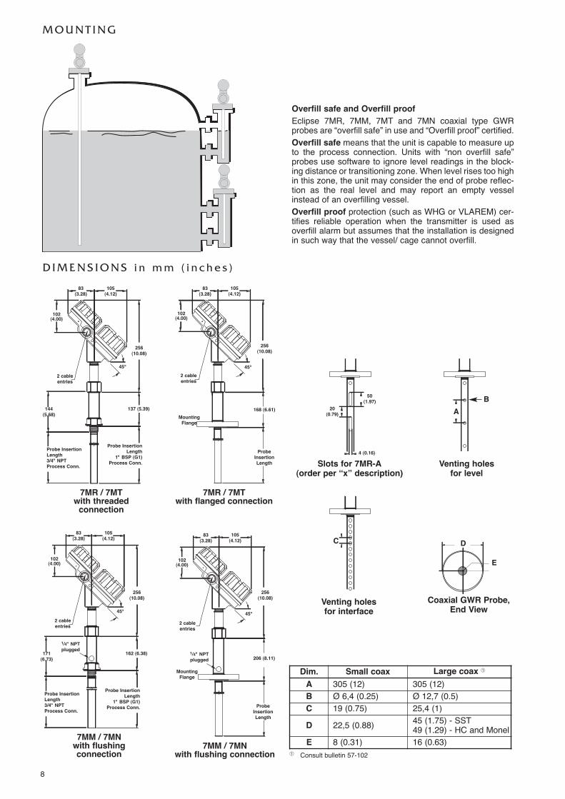
M O U N T I N G
D I M E N S I O N S i n m m ( i n c h e s )
137 (5.39)144(5.68)
83(3.28)
105(4.12)
256(10.08)
256(10.08)
102(4.00)
102(4.00)
2 cableentries
45°
7MR / 7MT with threadedconnection
Probe InsertionLength
1" BSP (G1)Process Conn.
Probe InsertionLength 3/4" NPTProcess Conn.
162 (6.38)171(6.73)
83(3.28)
105(4.12)
256(10.08)
102(4.00)
2 cableentries
45°
7MM / 7MN with flushingconnection
Probe InsertionLength
1" BSP (G1)Process Conn.
Probe InsertionLength 3/4" NPTProcess Conn.
168 (6.61)MountingFlange
7MR / 7MTwith flanged connection
83(3.28)
105(4.12)
2 cableentries
45°
ProbeInsertionLength
256(10.08)
102(4.00)
206 (8.11)
MountingFlange
1/4" NPTplugged
1/4" NPTplugged
7MM / 7MNwith flushing connection
83(3.28)
105(4.12)
2 cableentries
45°
ProbeInsertionLength
Coaxial GWR Probe,End View
Overfill safe and Overfill proofEclipse 7MR, 7MM, 7MT and 7MN coaxial type GWRprobes are “overfill safe” in use and “Overfill proof” certified. Overfill safe means that the unit is capable to measure upto the process connection. Units with “non overfill safe”probes use software to ignore level readings in the block-ing distance or transitioning zone. When level rises too highin this zone, the unit may consider the end of probe reflec-tion as the real level and may report an empty vesselinstead of an overfilling vessel. Overfill proof protection (such as WHG or VLAREM) cer-tifies reliable operation when the transmitter is used asoverfill alarm but assumes that the installation is designedin such way that the vessel/ cage cannot overfill.
Venting holesfor level
AB
C D
E
Venting holesfor interface
Slots for 7MR-A(order per “x” description)
50 (1.97)
20 (0.79)
4 (0.16)
Dim. Small coax Large coax �
A 305 (12) 305 (12)B Ø 6,4 (0.25) Ø 12,7 (0.5)C 19 (0.75) 25,4 (1)D 22,5 (0.88) 45 (1.75) - SST
49 (1.29) - HC and MonelE 8 (0.31) 16 (0.63)
9
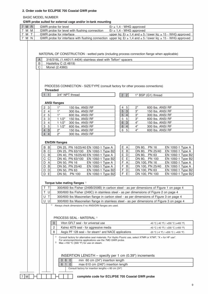
2. Order code for ECLIPSE 705 Coaxial GWR probe
7 M
MATERIAL OF CONSTRUCTION - wetted parts (including process connection flange when applicable)
complete code for ECLIPSE 705 Coaxial GWR probe
A 316/316L (1.4401/1.4404) stainless steel with Teflon® spacersB Hastelloy C (2.4819)C Monel (2.4360)
BASIC MODEL NUMBERGWR probe suited for external cage and/or in-tank mounting
7 M R GWR probe for level Er ≥ 1,4 - WHG approved7 M M GWR probe for level with flushing connection Er ≥ 1,4 - WHG approved7 M T GWR probe for interface upper liq: Er ≥ 1,4 and ≤ 5 / lower liq: ≥ 15 - WHG approved7 M N GWR probe for interface with flushing connection upper liq: Er ≥ 1,4 and ≤ 5 / lower liq: ≥ 15 - WHG approved
PROCESS CONNECTION - SIZE/TYPE (consult factory for other process connections)
1 1 3/4" NPT thread 2 2 1" BSP (G1) threadThreaded
2 3 1" 150 lbs. ANSI RF2 4 1" 300 lbs. ANSI RF2 5 1" 600 lbs. ANSI RF3 3 1 1/2" 150 lbs. ANSI RF3 4 1 1/2" 300 lbs. ANSI RF3 5 1 1/2" 600 lbs. ANSI RF4 3 2" 150 lbs. ANSI RF4 4 2" 300 lbs. ANSI RF
4 5 2" 600 lbs. ANSI RF5 3 3" 150 lbs. ANSI RF5 4 3" 300 lbs. ANSI RF5 5 3" 600 lbs. ANSI RF6 3 4" 150 lbs. ANSI RF6 4 4" 300 lbs. ANSI RF6 5 4" 600 lbs. ANSI RF
ANSI flanges
B B DN 25, PN 16/25/40 EN 1092-1 Type AB C DN 25, PN 63/100 EN 1092-1 Type B2C B DN 40, PN 16/25/40 EN 1092-1 Type AC C DN 40, PN 63/100 EN 1092-1 Type B2D A DN 50, PN 16 EN 1092-1 Type AD B DN 50, PN 25/40 EN 1092-1 Type AD D DN 50, PN 63 EN 1092-1 Type B2D E DN 50, PN 100 EN 1092-1 Type B2
E A DN 80, PN 16 EN 1092-1 Type AE B DN 80, PN 25/40 EN 1092-1 Type AE D DN 80, PN 63 EN 1092-1 Type B2E E DN 80, PN 100 EN 1092-1 Type B2F A DN 100, PN 16 EN 1092-1 Type AF B DN 100, PN 25/40 EN 1092-1 Type AF D DN 100, PN 63 EN 1092-1 Type B2F E DN 100, PN 100 EN 1092-1 Type B2
EN/DIN flanges
T T 300/600 lbs Fisher (249B/259B) in carbon steel - as per dimensions of Figure 1 on page 4T U 300/600 lbs Fisher (249C) in stainless steel - as per dimensions of Figure 2 on page 4U T 300/600 lbs Masoneilan flange in carbon steel - as per dimensions of Figure 3 on page 4U U 300/600 lbs Masoneilan flange in stainless steel - as per dimensions of Figure 3 on page 4
Torque tube mating flanges �
INSERTION LENGTH – specify per 1 cm (0.39") increments0 6 0 min 60 cm (24") insertion length6 1 0 max 610 cm (240") insertion length
PROCESS SEAL - MATERIAL �0 Viton GFLT seal - for universal use -40 °C (-40 °F) / +200 °C (+400 °F)2 Kalrez 4079 seal - for aggressive media -40 °C (-40 °F) / +200 °C (+400 °F)8 Aegis PF 128 seal – for steam� and NACE applications -20 °C (-4 °F) / +200 °C ( +400 °F)
� Consult factory for alternative seal materials. For Hydro Fluoric use, select X7MR or X7MT, "X = for HF use".For ammonia/chlorine applications use the 7MD GWR probe.
� Max +150 °C (300 °F) for use on steam.
� Always check dimensions if no ANSI/DIN flanges are used.
Consult factory for insertion lengths < 60 cm (24")

10
M O U N T I N G
D I M E N S I O N S i n m m ( i n c h e s )
7MB with threaded
2" BSP (G2) connection
7MBwith threaded
2" NPT connection7MB
with flanged connection
Overfill safe and Overfill protectionEclipse twin rod GWR probes use software to ignore levelreadings in the transitioning zone at the top of the GWRprobe. The maximum level is a minimum of 150 mm (6")below the process connection. This may include utilizing anozzle or spool piece to raise the probe. Twin rod probesare overfill proof certified but not overfill safe in use.
83(3.28)
105(4.12)
256(10.08)
103 (4)126 (4.96) 129 (5.08)
256(10.08)
256(10.08)
102(4.00)
2" BSP (G2)Process Conn.
2 cableentries
ProbeInsertionLength
45°
83(3.28)
105(4.12)
2" NPTProcess Conn.
2 cableentries
ProbeInsertionLength
45°
83(3.28)
105(4.12)
MountingFlange
2 cableentries
ProbeInsertionLength
45°
22,2 (0.875)
6,3 (0.248)
min 25 (1)
Tank or cage wall
Ø 13 (0.50)Rods
Twin Rod GWR Probe,End View
102(4.00)
102(4.00)
min Ø 3"/DN 80
max level
maxlevel
signal propagation
end view
Nozzles:The nozzle should be min. Ø 3”/DN80.

11
2. Order code for ECLIPSE 705 Twin Rod GWR probe
7 M B
MATERIAL OF CONSTRUCTION - wetted parts (including process connection flange when applicable)
complete order code for ECLIPSE 705 Twin Rod GWR probe
A 316/316L (1.4401/1.4404) stainless steel with TFE spacersB Hastelloy C (2.4819) with TFE spacersC Monel (2.4360) with TFE spacers
BASIC MODEL NUMBERGWR probe for in-tank mounting only
7 M B Twin Rod GWR probe for liquid level (dielectric range: ≥ 1,9) - WHG approved
PROCESS CONNECTION - SIZE/TYPE
4 1 2" NPT thread4 2 2" BSP (G2) thread
Threaded
5 3 3" 150 lbs. ANSI raised face flange5 4 3" 300 lbs. ANSI raised face flange6 3 4" 150 lbs. ANSI raised face flange6 4 4" 300 lbs. ANSI raised face flange
ANSI flanges (consult factory for 2" process connections)
E A DN 80, PN 16 EN 1092-1 Type AE B DN 80, PN 25/40 EN 1092-1 Type AE D DN 80, PN 63 EN 1092-1 Type B2F A DN 100, PN 16 EN 1092-1 Type AF B DN 100, PN 25/40 EN 1092-1 Type AF D DN 100, PN 63 EN 1092-1 Type B2
EN/DIN flanges (consult factory for DN 50 process connections)
INSERTION LENGTH – specify per 1 cm (0.39") increments(up to 22 m (75') with twin cable GWR probe, see page 18 and 19) 0 6 0 min 60 cm (24") insertion length6 1 0 max 610 cm (240") insertion length
PROCESS SEAL - MATERIAL �0 Viton GFLT seal - for universal use -40 °C (-40 °F) / +200 °C (+400 °F)2 Kalrez 4079 seal - for aggressive media -40 °C (-40 °F) / +200 °C (+400 °F)8 Aegis PF 128 seal – for NACE applications -20 °C (-4 °F) / +200 °C ( +400 °F)
� Consult factory for alternative seal materials. For Hydro Fluoric use, select X7MR or X7MT, "X = for HF use".For ammonia/chlorine applications use the 7MD GWR probe.
T T 300/600 lbs Fisher (249B/259B) in carbon steel - as per dimensions of Figure 1 on page 4T U 300/600 lbs Fisher (249C) in stainless steel - as per dimensions of Figure 2 on page 4U T 300/600 lbs Masoneilan flange in carbon steel - as per dimensions of Figure 3 on page 4U U 300/600 lbs Masoneilan flange in stainless steel - as per dimensions of Figure 3 on page 4
Torque tube mating flanges �
� Always check dimensions if no ANSI/DIN flanges are used.

12
D I M E N S I O N S i n m m ( i n c h e s )
7MD/7MSwith threaded connection
Overfill safe and Overfill protectionEclipse 7ML and 7MD coaxial type GWR probes are “over-fill safe” in use and “Overfill proof” certified.Overfill safe means that the unit is capable to measure upto the process connection. Units with “non overfill safe”probes use software to ignore level readings in the block-ing distance or transitioning zone. When level rises too highin this zone, the unit may consider the end of probe reflec-tion as the real level and may report an empty vesselinstead of an overfilling vessel. Overfill proof protection (such as WHG or VLAREM) cer-tifies reliable operation when the transmitter is used asoverfill alarm but assumes that the installation is designedin such way that the vessel/ cage cannot overfill.
7MD/7MS with flanged connection
7MD: 277 (10.90).7MS: 240 (9.45)
MountingFlange
83(3.28)
105(4.12)
256(10.08)
102(4.00)
2 cableentries
45°
ProbeInsertionLength
M O U N T I N G
7MD: 199 (7.83)7MS: 156 (6.14)7MD: 218 (8.58)
7MS: 177 (6.97)
83(3.28)
105(4.12)
256(10.08)
102(4.00)
2 cableentries
45°
Probe InsertionLength
1" BSP (G1)Process Conn.
Probe InsertionLength 3/4" NPTProcess Conn.
7ML with flanged connection
375 (14.76)
MountingFlange
83(3.28)
105(4.12)
256(10.08)
102(4.00)
2 cableentries
45°
ProbeInsertionLength
1/4" NPTplugged
7ML with threaded connection
297 (11.69)
83(3.28)
105(4.12)
256(10.08)
102(4.00)
2 cableentries
45°
ProbeInsertionLength
1/4" NPTplugged
Coaxial GWR Probe,End View
Venting holesfor all
A
C D
E
Venting holesfor 7MD/7ML
(order per “x” description)
Slots for 7MD - A/V/W(order per “x” description)
50 (1.97)
20 (0.79)
4 (0.16)
Dim. Small coax Large coax �
A 305 (12) 305 (12)B Ø 6,4 (0.25) Ø 12,7 (0.5)C 19 (0.75) 25,4 (1)D 22,5 (0.88) 45 (1.75) - SST
49 (1.29) - HC and MonelE 8 (0.31) 16 (0.63)
B
� Consult bulletin 57-102

13
2. Order code for ECLIPSE 705 High Temperature / High Pressure Coaxial GWR probe
7 NM
MATERIAL OF CONSTRUCTION (all wetted parts) AND MIN. DIELECTRICS
complete order code for ECLIPSE 705 High Temperature / High PressureCoaxial GWR probe
W 316/316L (1.4401/1.4404) stainless steel with Teflon® spacers min. dielectrics: ≥ 1,4 / max +200 °CV 316/316L (1.4401/1.4404) SST with H. Temp PEEK® spacers min. dielectrics: ≥ 1,7 / max +345 °CA 316/316L (1.4401/1.4404) SST with ceramic spacers min. dielectrics: ≥ 2,0 / max +430 °CB Hastelloy C (2.4819) with ceramic spacers min. dielectrics: ≥ 2,0 / max +430 °CC Monel (2.4360) with ceramic spacers min. dielectrics: ≥ 2,0 / max +430 °C
PROCESS SEAL MATERIALN Borosilicate / Inconel® X-750 seal – for non steam applications -196 °C (-320 °F) / +400 °C (+750 °F)�
PROCESS CONNECTION - SIZE/TYPE (consult factory for other process connections)
2 3 1" 150 lbs. ANSI RF2 4 1" 300 lbs. ANSI RF2 5 1" 600 lbs. ANSI RF2 K 1" 600 lbs. ANSI RJ2 L 1" 900 lbs. ANSI RJ3 3 1 1/2" 150 lbs. ANSI RF3 4 1 1/2" 300 lbs. ANSI RF3 5 1 1/2" 600 lbs. ANSI RF3 K 1 1/2" 600 lbs. ANSI RJ3 M 1 1/2" 900/1500 lbs. ANSI RJ3 N 1 1/2" 2500 lbs. ANSI RJ4 3 2" 150 lbs. ANSI RF4 4 2" 300 lbs. ANSI RF4 5 2" 600 lbs. ANSI RF4 K 2" 600 lbs. ANSI RJ4 M 2" 900/1500 lbs. ANSI RJ
4 N 2" 2500 lbs. ANSI RJ5 3 3" 150 lbs. ANSI RF5 4 3" 300 lbs. ANSI RF5 5 3" 600 lbs. ANSI RF5 K 3" 600 lbs. ANSI RJ5 L 3" 900 lbs. ANSI RJ5 M 3" 1500 lbs. ANSI RJ5 N 3" 2500 lbs. ANSI RJ6 3 4" 150 lbs. ANSI RF6 4 4" 300 lbs. ANSI RF6 5 4" 600 lbs. ANSI RF6 K 4" 600 lbs. ANSI RJ6 L 4" 900 lbs. ANSI RJ6 M 4" 1500 lbs. ANSI RJ6 N 4" 2500 lbs. ANSI RJ
ANSI flanges
B B DN 25, PN 16/25/40 EN 1092-1 Type AB C DN 25, PN 63/100 EN 1092-1 Type B2B F DN 25, PN 160 EN 1092-1 Type B2C B DN 40, PN 16/25/40 EN 1092-1 Type AC C DN 40, PN 63/100 EN 1092-1 Type B2C F DN 40, PN 160 EN 1092-1 Type B2C G DN 40, PN 250 EN 1092-1 Type B2C H DN 40, PN 320 EN 1092-1 Type B2C J DN 40, PN 400 EN 1092-1 Type B2D A DN 50, PN 16 EN 1092-1 Type AD B DN 50, PN 25/40 EN 1092-1 Type AD D DN 50, PN 63 EN 1092-1 Type B2D E DN 50, PN 100 EN 1092-1 Type B2D F DN 50, PN 160 EN 1092-1 Type B2D G DN 50, PN 250 EN 1092-1 Type B2D H DN 50, PN 320 EN 1092-1 Type B2
D J DN 50, PN 400 EN 1092-1 Type B2E A DN 80, PN 16 EN 1092-1 Type AE B DN 80, PN 25/40 EN 1092-1 Type AE D DN 80, PN 63 EN 1092-1 Type B2E E DN 80, PN 100 EN 1092-1 Type B2E F DN 80, PN 160 EN 1092-1 Type B2E G DN 80, PN 250 EN 1092-1 Type B2E H DN 80, PN 320 EN 1092-1 Type B2E J DN 80, PN 400 EN 1092-1 Type B2F A DN 100, PN 16 EN 1092-1 Type AF B DN 100, PN 25/40 EN 1092-1 Type AF D DN 100, PN 63 EN 1092-1 Type B2F E DN 100, PN 100 EN 1092-1 Type B2F F DN 100, PN 160 EN 1092-1 Type B2F G DN 100, PN 250 EN 1092-1 Type B2F H DN 100, PN 320 EN 1092-1 Type B2F J DN 100, PN 400 EN 1092-1 Type B2
EN/DIN flanges
INSERTION LENGTH – specify per 1 cm (0.39") increments0 6 0 min 60 cm (24") insertion length6 1 0 max 610 cm (240") insertion length
7 M D HTHP GWR probe for level WHG approved7 M L HTHP GWR probe for level with flushing connection WHG approved
T T 300/600 lbs Fisher (249B/259B) in carbon steel - as per dimensions of Figure 1 on page 4T U 300/600 lbs Fisher (249C) in stainless steel - as per dimensions of Figure 2 on page 4U T 300/600 lbs Masoneilan flange in carbon steel - as per dimensions of Figure 3 on page 4U U 300/600 lbs Masoneilan flange in stainless steel - as per dimensions of Figure 3 on page 4
Torque tube mating flanges (always check dimensions if no ANSI / EN/DIN flanges are used)
1 1 3/4" NPT thread 2 2 1" BSP (G1) threadThreaded
� 7MD-W: max +200 °C (+400 °F) – 7MD-V: max +345 °C (+650 °F)
Consult factory for insertion lengths < 60 cm (24")
14
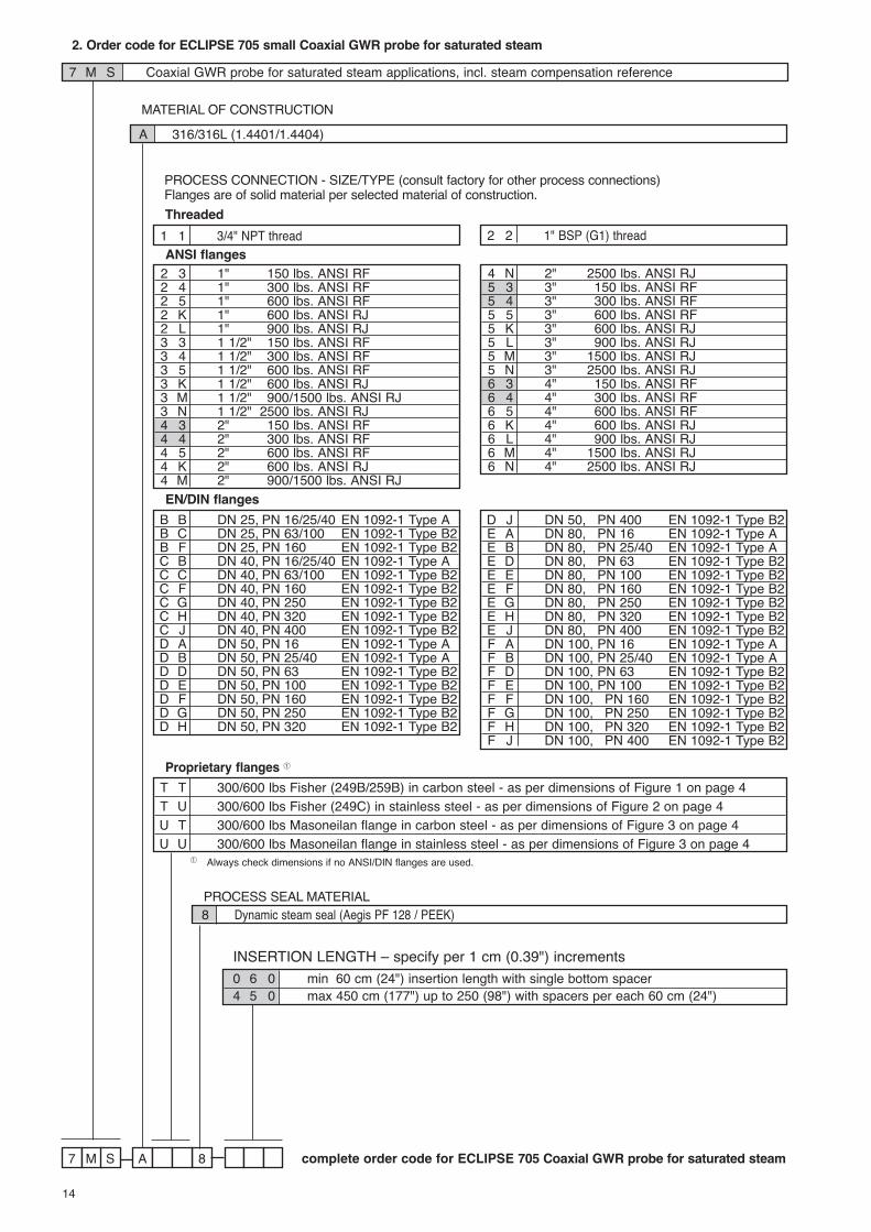
2. Order code for ECLIPSE 705 small Coaxial GWR probe for saturated steam
7 8AM S
MATERIAL OF CONSTRUCTION
complete order code for ECLIPSE 705 Coaxial GWR probe for saturated steam
A 316/316L (1.4401/1.4404)
7 M S Coaxial GWR probe for saturated steam applications, incl. steam compensation reference
PROCESS SEAL MATERIAL8 Dynamic steam seal (Aegis PF 128 / PEEK)
PROCESS CONNECTION - SIZE/TYPE (consult factory for other process connections)Flanges are of solid material per selected material of construction.
T T 300/600 lbs Fisher (249B/259B) in carbon steel - as per dimensions of Figure 1 on page 4T U 300/600 lbs Fisher (249C) in stainless steel - as per dimensions of Figure 2 on page 4U T 300/600 lbs Masoneilan flange in carbon steel - as per dimensions of Figure 3 on page 4U U 300/600 lbs Masoneilan flange in stainless steel - as per dimensions of Figure 3 on page 4
Proprietary flanges �
� Always check dimensions if no ANSI/DIN flanges are used.
INSERTION LENGTH – specify per 1 cm (0.39") increments0 6 0 min 60 cm (24") insertion length with single bottom spacer4 5 0 max 450 cm (177") up to 250 (98") with spacers per each 60 cm (24")
2 3 1" 150 lbs. ANSI RF2 4 1" 300 lbs. ANSI RF2 5 1" 600 lbs. ANSI RF2 K 1" 600 lbs. ANSI RJ2 L 1" 900 lbs. ANSI RJ3 3 1 1/2" 150 lbs. ANSI RF3 4 1 1/2" 300 lbs. ANSI RF3 5 1 1/2" 600 lbs. ANSI RF3 K 1 1/2" 600 lbs. ANSI RJ3 M 1 1/2" 900/1500 lbs. ANSI RJ3 N 1 1/2" 2500 lbs. ANSI RJ4 3 2" 150 lbs. ANSI RF4 4 2" 300 lbs. ANSI RF4 5 2" 600 lbs. ANSI RF4 K 2" 600 lbs. ANSI RJ4 M 2" 900/1500 lbs. ANSI RJ
4 N 2" 2500 lbs. ANSI RJ5 3 3" 150 lbs. ANSI RF5 4 3" 300 lbs. ANSI RF5 5 3" 600 lbs. ANSI RF5 K 3" 600 lbs. ANSI RJ5 L 3" 900 lbs. ANSI RJ5 M 3" 1500 lbs. ANSI RJ5 N 3" 2500 lbs. ANSI RJ6 3 4" 150 lbs. ANSI RF6 4 4" 300 lbs. ANSI RF6 5 4" 600 lbs. ANSI RF6 K 4" 600 lbs. ANSI RJ6 L 4" 900 lbs. ANSI RJ6 M 4" 1500 lbs. ANSI RJ6 N 4" 2500 lbs. ANSI RJ
ANSI flanges
B B DN 25, PN 16/25/40 EN 1092-1 Type AB C DN 25, PN 63/100 EN 1092-1 Type B2B F DN 25, PN 160 EN 1092-1 Type B2C B DN 40, PN 16/25/40 EN 1092-1 Type AC C DN 40, PN 63/100 EN 1092-1 Type B2C F DN 40, PN 160 EN 1092-1 Type B2C G DN 40, PN 250 EN 1092-1 Type B2C H DN 40, PN 320 EN 1092-1 Type B2C J DN 40, PN 400 EN 1092-1 Type B2D A DN 50, PN 16 EN 1092-1 Type AD B DN 50, PN 25/40 EN 1092-1 Type AD D DN 50, PN 63 EN 1092-1 Type B2D E DN 50, PN 100 EN 1092-1 Type B2D F DN 50, PN 160 EN 1092-1 Type B2D G DN 50, PN 250 EN 1092-1 Type B2D H DN 50, PN 320 EN 1092-1 Type B2
D J DN 50, PN 400 EN 1092-1 Type B2E A DN 80, PN 16 EN 1092-1 Type AE B DN 80, PN 25/40 EN 1092-1 Type AE D DN 80, PN 63 EN 1092-1 Type B2E E DN 80, PN 100 EN 1092-1 Type B2E F DN 80, PN 160 EN 1092-1 Type B2E G DN 80, PN 250 EN 1092-1 Type B2E H DN 80, PN 320 EN 1092-1 Type B2E J DN 80, PN 400 EN 1092-1 Type B2F A DN 100, PN 16 EN 1092-1 Type AF B DN 100, PN 25/40 EN 1092-1 Type AF D DN 100, PN 63 EN 1092-1 Type B2F E DN 100, PN 100 EN 1092-1 Type B2F F DN 100, PN 160 EN 1092-1 Type B2F G DN 100, PN 250 EN 1092-1 Type B2F H DN 100, PN 320 EN 1092-1 Type B2F J DN 100, PN 400 EN 1092-1 Type B2
EN/DIN flanges
1 1 3/4" NPT thread 2 2 1" BSP (G1) threadThreaded
15
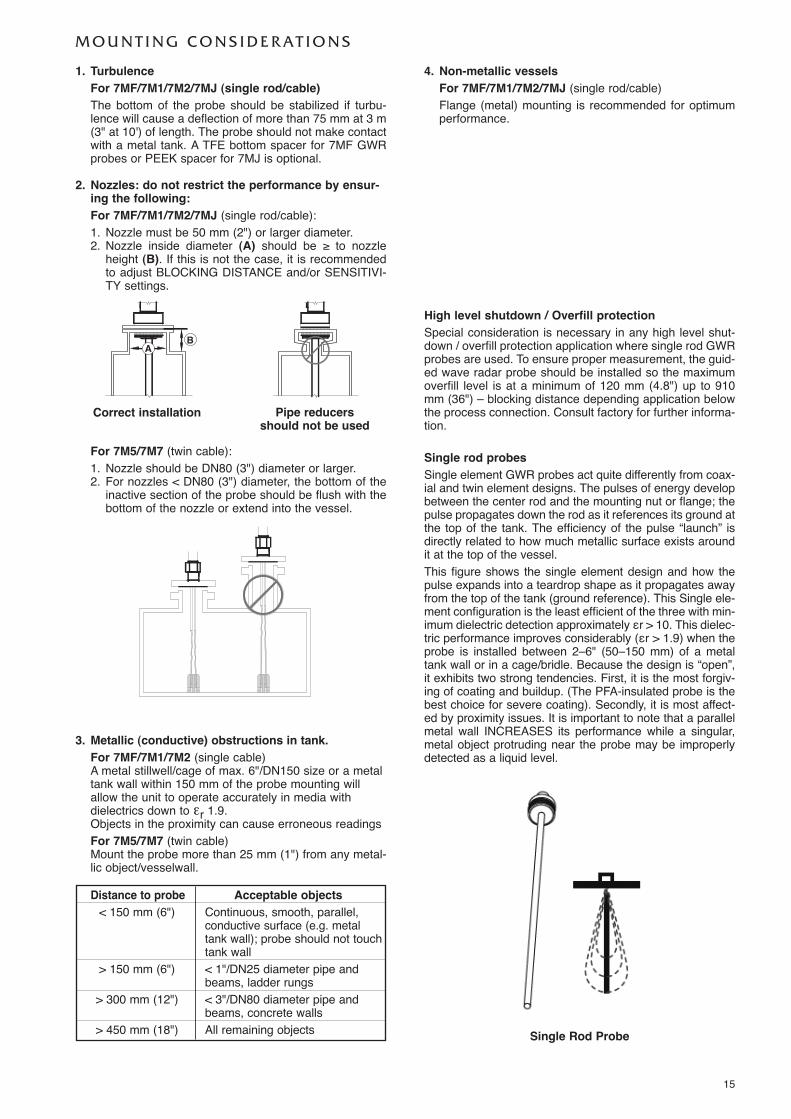
M O U N T I N G C O N S I D E R AT I O N S
High level shutdown / Overfill protectionSpecial consideration is necessary in any high level shut-down / overfill protection application where single rod GWRprobes are used. To ensure proper measurement, the guid-ed wave radar probe should be installed so the maximumoverfill level is at a minimum of 120 mm (4.8") up to 910mm (36") – blocking distance depending application belowthe process connection. Consult factory for further informa-tion.
1. TurbulenceFor 7MF/7M1/7M2/7MJ (single rod/cable)The bottom of the probe should be stabilized if turbu-lence will cause a deflection of more than 75 mm at 3 m(3" at 10') of length. The probe should not make contactwith a metal tank. A TFE bottom spacer for 7MF GWRprobes or PEEK spacer for 7MJ is optional.
2. Nozzles: do not restrict the performance by ensur-ing the following: For 7MF/7M1/7M2/7MJ (single rod/cable):1. Nozzle must be 50 mm (2") or larger diameter.2. Nozzle inside diameter (A) should be ≥ to nozzle
height (B). If this is not the case, it is recommendedto adjust BLOCKING DISTANCE and/or SENSITIVI-TY settings.
Pipe reducers should not be used
Distance to probe Acceptable objects< 150 mm (6") Continuous, smooth, parallel,
conductive surface (e.g. metaltank wall); probe should not touchtank wall
> 150 mm (6") < 1"/DN25 diameter pipe andbeams, ladder rungs
> 300 mm (12") < 3"/DN80 diameter pipe andbeams, concrete walls
> 450 mm (18") All remaining objects
3. Metallic (conductive) obstructions in tank.For 7MF/7M1/7M2 (single cable)A metal stillwell/cage of max. 6"/DN150 size or a metaltank wall within 150 mm of the probe mounting willallow the unit to operate accurately in media withdielectrics down to εr 1.9.Objects in the proximity can cause erroneous readingsFor 7M5/7M7 (twin cable)Mount the probe more than 25 mm (1") from any metal-lic object/vesselwall.
Correct installation
AB
4. Non-metallic vesselsFor 7MF/7M1/7M2/7MJ (single rod/cable)Flange (metal) mounting is recommended for optimumperformance.
For 7M5/7M7 (twin cable):1. Nozzle should be DN80 (3") diameter or larger.2. For nozzles < DN80 (3") diameter, the bottom of the
inactive section of the probe should be flush with thebottom of the nozzle or extend into the vessel.
Single rod probesSingle element GWR probes act quite differently from coax-ial and twin element designs. The pulses of energy developbetween the center rod and the mounting nut or flange; thepulse propagates down the rod as it references its ground atthe top of the tank. The efficiency of the pulse “launch” isdirectly related to how much metallic surface exists aroundit at the top of the vessel.This figure shows the single element design and how thepulse expands into a teardrop shape as it propagates awayfrom the top of the tank (ground reference). This Single ele-ment configuration is the least efficient of the three with min-imum dielectric detection approximately εr > 10. This dielec-tric performance improves considerably (εr > 1.9) when theprobe is installed between 2–6" (50–150 mm) of a metaltank wall or in a cage/bridle. Because the design is “open”,it exhibits two strong tendencies. First, it is the most forgiv-ing of coating and buildup. (The PFA-insulated probe is thebest choice for severe coating). Secondly, it is most affect-ed by proximity issues. It is important to note that a parallelmetal wall INCREASES its performance while a singular,metal object protruding near the probe may be improperlydetected as a liquid level.
Single Rod Probe

16
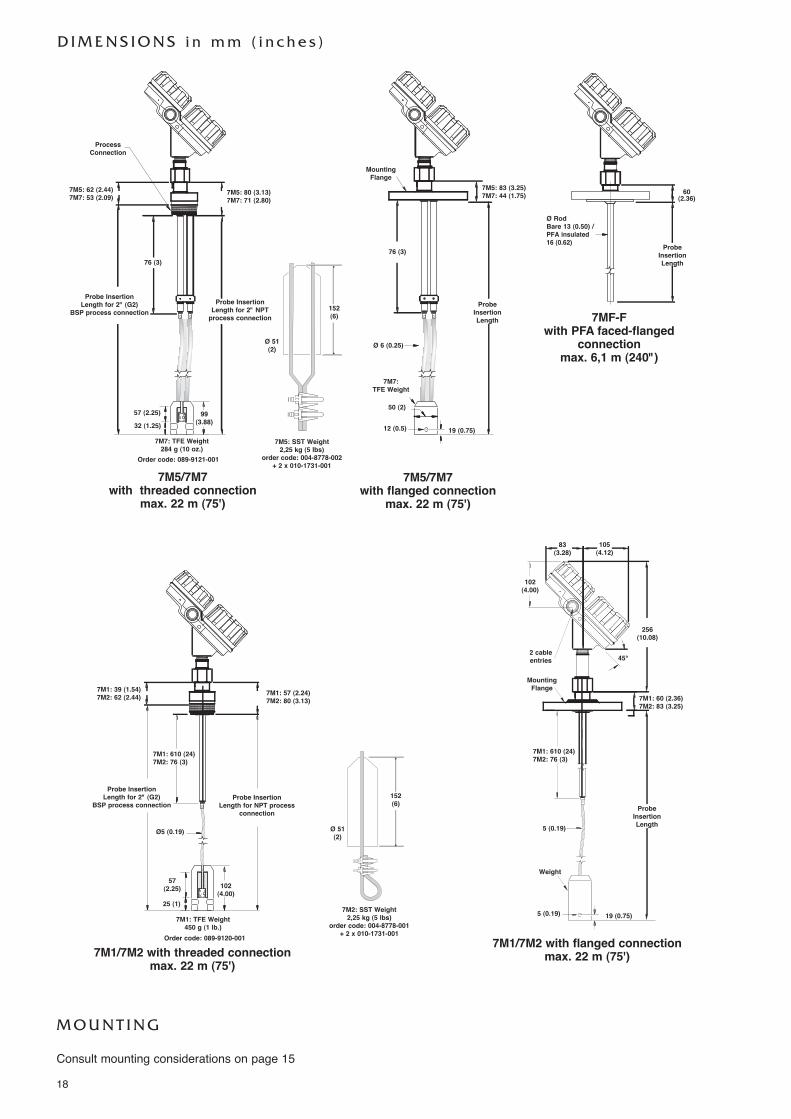
D I M E N S I O N S i n m m ( i n c h e s )
7MF/7MJ with threaded connection
max. 6,1 m (240")
7MF/7MJ with flanged connection
max. 6,1 m (240")
83(3.28)
105(4.12)
256(10.08)
36 (1.42)60 (2.36)
57 (2.24)
Optional Spacer Optional Spacer
102(4.00)
Ø RodBare 13 (0.50) /PFA insulated 16 (0.62)
Process Conn.
2 cableentries
Probe InsertionLength for 2" (G2)
BSP process connectionProbe InsertionLength for 2" NPT process connection
45°
13 (0.50) Ø Rod
ProbeInsertionLength
M O U N T I N G
Consult mounting considerations on page 15
Spacer (end view)
49(1.90)

17
2. Order code for ECLIPSE 705 GWR probe for liquids (for in-tank mounting only)- 316/316L (1.4401/1.4404) material for standard applications- Hastelloy C (2.4819) or Monel (2.4360) for extreme aggressive media- PFA insulated for applications with excessive coating / build up.
7 M
MATERIAL OF CONSTRUCTION
complete order code for ECLIPSE 705 - bare or PFA insulated GWR probe
A 316/316L (1.4401/1.4404) stainless steel for 7MF/7MJB Hastelloy C (2.4819) for 7MF/7MJC Monel (2.4360) for 7MF/7MJ4 PFA insulated 316/316L (1.4401/1.4404) SST for 7MF
BASIC MODEL NUMBER7 M F Standard single rod GWR probe (dielectric range: ≥ 1,9/10)�7 M J High temperature / high pressure single rod GWR probe (dielectric range: ≥ 1,9/10)�
PROCESS CONNECTION - SIZE/TYPE
4 1 2" NPT thread4 2 2" BSP (G2) thread
Threaded
4 3 2" 150 lbs. ANSI RF4 4 2" 300 lbs. ANSI RF4 5 2" 600 lbs. ANSI RF4 K 2" 600 lbs. ANSI RJ4 M 2" 900/1500 lbs. ANSI RJ5 3 3" 150 lbs. ANSI RF flange5 4 3" 300 lbs. ANSI RF flange5 5 3" 600 lbs. ANSI RF flange5 K 3" 600 lbs. ANSI RJ flange5 L 3" 900 lbs. ANSI RJ flange5 M 3" 1500 lbs. ANSI RJ flange6 3 4" 150 lbs. ANSI RF flange6 4 4" 300 lbs. ANSI RF flange6 5 4" 600 lbs. ANSI RF flange6 K 4" 600 lbs. ANSI RJ flange6 L 4" 900 lbs. ANSI RJ flange6 M 4" 1500 lbs. ANSI RJ flange
ANSI flanged �
D A DN 50, PN 16 EN 1092-1 Type AD B DN 50, PN 25/40 EN 1092-1 Type AD D DN 50, PN 63 EN 1092-1 Type B2D E DN 50, PN 100 EN 1092-1 Type B2D F DN 50, PN 160 EN 1092-1 Type B2D G DN 50, PN 250 EN 1092-1 Type B2E A DN 80, PN 16 EN 1092-1 Type AE B DN 80, PN 25/40 EN 1092-1 Type AE D DN 80, PN 63 EN 1092-1 Type B2E E DN 80, PN 100 EN 1092-1 Type B2E F DN 80, PN 160 EN 1092-1 Type B2E G DN 80, PN 250 EN 1092-1 Type B2F A DN 100, PN 16 EN 1092-1 Type AF B DN 100, PN 25/40 EN 1092-1 Type AF D DN 100, PN 63 EN 1092-1 Type B2F E DN 100, PN 100 EN 1092-1 Type B2F F DN 100, PN 160 EN 1092-1 Type B2F G DN 100, PN 250 EN 1092-1 Type B2
EN/DIN flanged �
INSERTION LENGTH – Specify insertion length per cm (0.39") increments0 6 0 minimum 60 cm (24") insertion length6 1 0 maximum 610 cm (240") insertion length
PROCESS SEAL - MATERIALFor 7MF0 Viton® GFLT seal - for universal use -40 °C (-40 °F) / +150 °C (+300 °F)2 Kalrez 4079 seal - for aggressive media -40 °C (-40 °F) / +150 °C (+300 °F)8 Aegis PF 128 seal - for NACE applications -20 °C (-4 °F) / +150 °C (+300 °F)
For 7MJ8 PEEK/Aegis PF 128 seal -15 °C (-0 °F) / +315 °C (+600 °F)
Consult factory for alternative seal materials. For Ammonia/Chlorine applications, use the 7MD GWR probe.Viton® is a registered trademark of DuPont Performance Elastomers.
� 7MF up to 600 lbs ANSI RF / PN 100 flanges
� For dielectric range ≥ 1,9 and < 10, probe must be mounted within 50 - 150 mm (2" - 6") distance from the tank wall or in a cage or bridle. Seemounting considerations on page 5
D I M E N S I O N S i n m m ( i n c h e s )
7MF-Fwith PFA faced-flanged
connectionmax. 6,1 m (240")
7M1/7M2 with flanged connectionmax. 22 m (75')7M1/7M2 with threaded connection
max. 22 m (75')
256(10.08)
7M1: 39 (1.54)7M2: 62 (2.44) 7M1: 57 (2.24)
7M2: 80 (3.13)
Ø RodBare 13 (0.50) /PFA insulated 16 (0.62)
Probe InsertionLength for 2" NPTprocess connection
Probe InsertionLength for 2" (G2)
BSP process connection
Probe InsertionLength for NPT process
connection
Probe InsertionLength for 2" (G2)
BSP process connection
60(2.36)
ProbeInsertionLength
83(3.28)
105(4.12)
7M1: 610 (24)7M2: 76 (3)
7M1: 60 (2.36)7M2: 83 (3.25)
7M1: 610 (24)7M2: 76 (3)
5 (0.19)
Ø 6 (0.25)
19 (0.75)
5 (0.19)Ø5 (0.19)
57(2.25) 102
(4.00)25 (1)
MountingFlange
Weight
2 cableentries
ProbeInsertionLength
45°
102(4.00)
7M5/7M7 with threaded connection
max. 22 m (75')
76 (3)76 (3)
7M5: 62 (2.44)7M7: 53 (2.09) 7M5: 80 (3.13)
7M7: 71 (2.80)7M5: 83 (3.25)7M7: 44 (1.75)
99(3.88)
57 (2.25)
7M7: TFE Weight284 g (10 oz.)
7M1: TFE Weight450 g (1 lb.)
7M2: SST Weight2,25 kg (5 lbs)
order code: 004-8778-001+ 2 x 010-1731-001
32 (1.25)
ProcessConnection
Order code: 089-9121-001
Order code: 089-9120-001
7M5/7M7 with flanged connection
max. 22 m (75')
19 (0.75)
7M7: TFE Weight
12 (0.5)
50 (2)
MountingFlange
ProbeInsertionLength
7M5: SST Weight2,25 kg (5 lbs)
order code: 004-8778-002+ 2 x 010-1731-001
Ø 51(2)
152 (6)
Ø 51(2)
152 (6)
M O U N T I N G
Consult mounting considerations on page 15
18
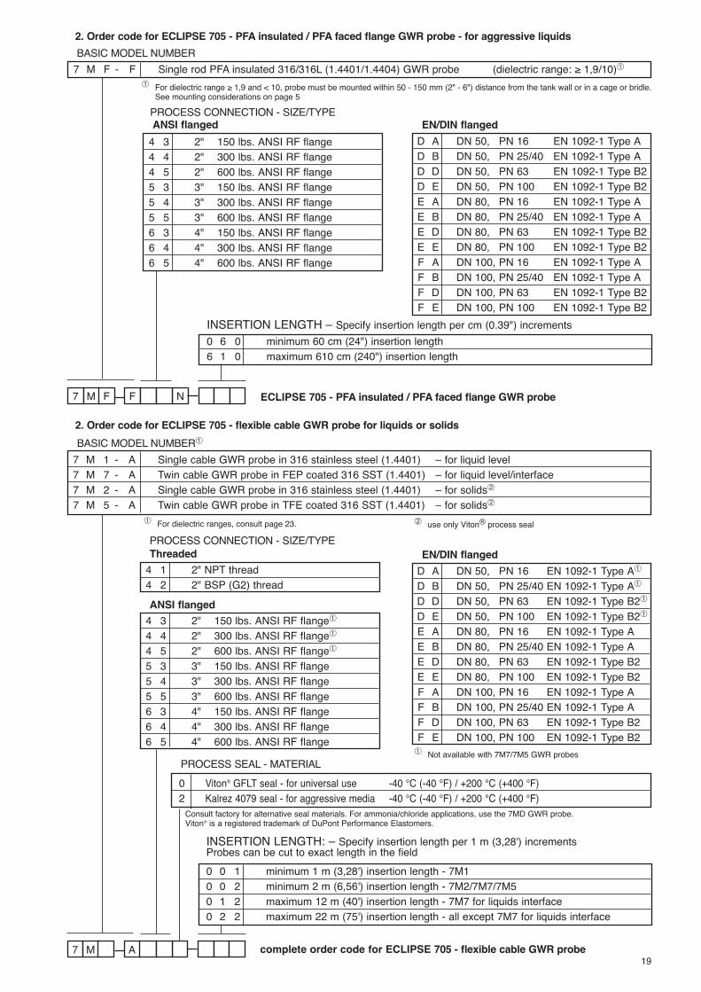
2. Order code for ECLIPSE 705 - PFA insulated / PFA faced flange GWR probe - for aggressive liquids
2. Order code for ECLIPSE 705 - flexible cable GWR probe for liquids or solids
7 AM complete order code for ECLIPSE 705 - flexible cable GWR probe
BASIC MODEL NUMBER�
PROCESS CONNECTION - SIZE/TYPE
4 1 2" NPT thread4 2 2" BSP (G2) thread
Threaded
4 3 2" 150 lbs. ANSI RF flange�
4 4 2" 300 lbs. ANSI RF flange�
4 5 2" 600 lbs. ANSI RF flange�
5 3 3" 150 lbs. ANSI RF flange5 4 3" 300 lbs. ANSI RF flange5 5 3" 600 lbs. ANSI RF flange6 3 4" 150 lbs. ANSI RF flange6 4 4" 300 lbs. ANSI RF flange6 5 4" 600 lbs. ANSI RF flange
ANSI flanged
INSERTION LENGTH: – Specify insertion length per 1 m (3,28') incrementsProbes can be cut to exact length in the field0 0 1 minimum 1 m (3,28') insertion length - 7M10 0 2 minimum 2 m (6,56') insertion length - 7M2/7M7/7M50 1 2 maximum 12 m (40') insertion length - 7M7 for liquids interface0 2 2 maximum 22 m (75') insertion length - all except 7M7 for liquids interface
PROCESS SEAL - MATERIAL0 Viton® GFLT seal - for universal use -40 °C (-40 °F) / +200 °C (+400 °F)2 Kalrez 4079 seal - for aggressive media -40 °C (-40 °F) / +200 °C (+400 °F)
7 M 1 - A Single cable GWR probe in 316 stainless steel (1.4401) – for liquid level7 M 7 - A Twin cable GWR probe in FEP coated 316 SST (1.4401) – for liquid level/interface7 M 2 - A Single cable GWR probe in 316 stainless steel (1.4401) – for solids�
7 M 5 - A Twin cable GWR probe in TFE coated 316 SST (1.4401) – for solids�
Consult factory for alternative seal materials. For ammonia/chloride applications, use the 7MD GWR probe.Viton® is a registered trademark of DuPont Performance Elastomers.
7 NFM F ECLIPSE 705 - PFA insulated / PFA faced flange GWR probe
BASIC MODEL NUMBER
PROCESS CONNECTION - SIZE/TYPE
4 3 2" 150 lbs. ANSI RF flange4 4 2" 300 lbs. ANSI RF flange4 5 2" 600 lbs. ANSI RF flange5 3 3" 150 lbs. ANSI RF flange5 4 3" 300 lbs. ANSI RF flange5 5 3" 600 lbs. ANSI RF flange6 3 4" 150 lbs. ANSI RF flange6 4 4" 300 lbs. ANSI RF flange6 5 4" 600 lbs. ANSI RF flange
ANSI flanged
INSERTION LENGTH – Specify insertion length per cm (0.39") increments0 6 0 minimum 60 cm (24") insertion length6 1 0 maximum 610 cm (240") insertion length
7 M F - F Single rod PFA insulated 316/316L (1.4401/1.4404) GWR probe (dielectric range: ≥ 1,9/10)�
D A DN 50, PN 16 EN 1092-1 Type AD B DN 50, PN 25/40 EN 1092-1 Type AD D DN 50, PN 63 EN 1092-1 Type B2D E DN 50, PN 100 EN 1092-1 Type B2E A DN 80, PN 16 EN 1092-1 Type AE B DN 80, PN 25/40 EN 1092-1 Type AE D DN 80, PN 63 EN 1092-1 Type B2E E DN 80, PN 100 EN 1092-1 Type B2F A DN 100, PN 16 EN 1092-1 Type AF B DN 100, PN 25/40 EN 1092-1 Type AF D DN 100, PN 63 EN 1092-1 Type B2F E DN 100, PN 100 EN 1092-1 Type B2
EN/DIN flanged
D A DN 50, PN 16 EN 1092-1 Type A�
D B DN 50, PN 25/40 EN 1092-1 Type A�
D D DN 50, PN 63 EN 1092-1 Type B2�
D E DN 50, PN 100 EN 1092-1 Type B2�
E A DN 80, PN 16 EN 1092-1 Type AE B DN 80, PN 25/40 EN 1092-1 Type AE D DN 80, PN 63 EN 1092-1 Type B2E E DN 80, PN 100 EN 1092-1 Type B2F A DN 100, PN 16 EN 1092-1 Type AF B DN 100, PN 25/40 EN 1092-1 Type AF D DN 100, PN 63 EN 1092-1 Type B2F E DN 100, PN 100 EN 1092-1 Type B2
EN/DIN flanged
19
� use only Viton® process seal
� Not available with 7M7/7M5 GWR probes
� For dielectric range ≥ 1,9 and < 10, probe must be mounted within 50 - 150 mm (2" - 6") distance from the tank wall or in a cage or bridle.See mounting considerations on page 5
� For dielectric ranges, consult page 23.
T R A N S M I T T E R S P E C I F I C AT I O N S
FUNCTIONAL/PHYSICAL
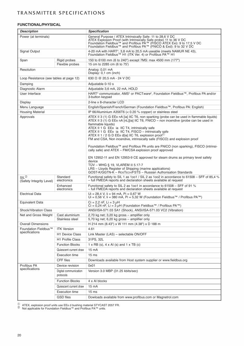
� ATEX, explosion proof units use EEx d bushing material STYCAST 2057 FR.� Not applicable for Foundation Fieldbus™ and Profibus PA™ units.
Description SpecificationPower (at terminals) General Purpose / ATEX Intrinsically Safe: 11 to 28,6 V DC
ATEX Explosion Proof (with Intrinsically Safe probe) 11 to 36 V DCFoundation Fieldbus™ and Profibus PA™ (FISCO ATEX Exi): 9 to 17,5 V DCFoundation Fieldbus™ and Profibus PA™ (FNICO & Exd): 9 to 32 V DC
Signal Output 4-20 mA with HART®, 3,8 mA to 20,5 mA useable (meets NAMUR NE 43),Foundation Fieldbus™ H1 (ITK Ver. 4) or Profibus PA™ H1
Span Rigid probes 150 to 6100 mm (6 to 240") except 7MS: max 4500 mm (177")Flexible probes 15 cm to 2285 cm (6 to 75')
Resolution Analog: 0,01 mADisplay: 0,1 cm (inch)
Loop Resistance (see tables at page 12) 630 Ω @ 20,5 mA - 24 V DCDamping Adjustable 0-10 sDiagnostic Alarm Adjustable 3,6 mA, 22 mA, HOLDUser Interface HART® communicator, AMS® or PACTware®, Foundation Fieldbus™, Profibus PA and/or
3-button keypad Display 2-line x 8-character LCDMenu Language English/Spanish/French/German (Foundation Fieldbus™, Profibus PA: English)Housing Material IP 66/Aluminium A356T6 (< 0.20 % copper) or stainless steelApprovals ATEX II 3 (1) G EEx nA [ia] IIC T6, non sparking (probe can be used in flammable liquids)
ATEX II 3 (1) G EEx nA [nL][ia] IIC T6, FNICO – non incendive (probe can be used inflammable liquids)ATEX II 1 G EEx ia IIC T4, intrinsically safeATEX II 1 G EEx ia IIC T4, FISCO – intrinsically safeATEX II 1 / 2 G D EEx d[ia] IIC T6, explosion proof�FM and CSA, Non incendive, intrinsically safe (FISCO) and explosion proof
Foundation Fieldbus™ and Profibus PA units are FNICO (non sparking), FISCO (intrinsi-cally safe) and ATEX – FM/CSA explosion proof approved
EN 12952-11 and EN 12953-9 CE approved for steam drums as primary level safetydeviceTÜV – WHG § 19, VLAREM II 5.17-7LRS – Lloyds Register of Shipping (marine applications)GOST-K/GGTN-K – ROSTECH/FSTS – Russian Authorisation Standards
SIL�
(Safety Integrity Level)Standard electronics
Functional safety to SIL 1 as 1oo1 / SIL 2 as 1oo2 in accordance to 61508 – SFF of 85,4 %– full FMEDA reports and declaration sheets available at request
Enhanced electronics
Functional safety to SIL 2 as 1oo1 in accordance to 61508 – SFF of 91 %– full FMEDA reports and declaration sheets available at request
Electrical Data Ui = 28,4 V, li = 94 mA, Pi = 0,67 WUi = 0,56 V, li = 380 mA, Pi = 5,32 W (Foundation Fieldbus™ / Profibus PA™)
Equivalent Data Ci = 2,2 nF, Li = 3 µHCi = 0,24 nF, Li = 3 µH (Foundation Fieldbus™ / Profibus PA™)
Shock/Vibration Class ANSI/ISA-571.03 SA1 (Shock), ANSI/ISA-571.03 VC2 (Vibration)Net and Gross Weight Cast aluminium 2,70 kg net; 3,20 kg gross – amplifier only
Stainless steel 5,70 kg net; 6,20 kg gross – amplifier onlyOverall Dimensions H 214 mm (8.43") x W 111 mm (4.38") x D 188 mFoundation Fieldbus™specifications
ITK Version 4.61H1 Device Class Link Master (LAS) – selectable ON/OFFH1 Profile Class 31PS, 32LFunction Blocks 1 x RB (s), 4 x AI (s) and 1 x TB (c)Quiescent current draw 15 mAExecution time 15 msCFF files Downloads available from Host system supplier or www.fieldbus.org
Profibus PA specifications
Device revision 0x01Digital communicationprotocols
Version 3.0 MBP (31.25 kbits/sec)
Function Blocks 4 x Al blocksQuiescent current draw 15 mAExecution time 15 msGSD files Dowloads available from www.profibus.com or Magnetrol.com
20
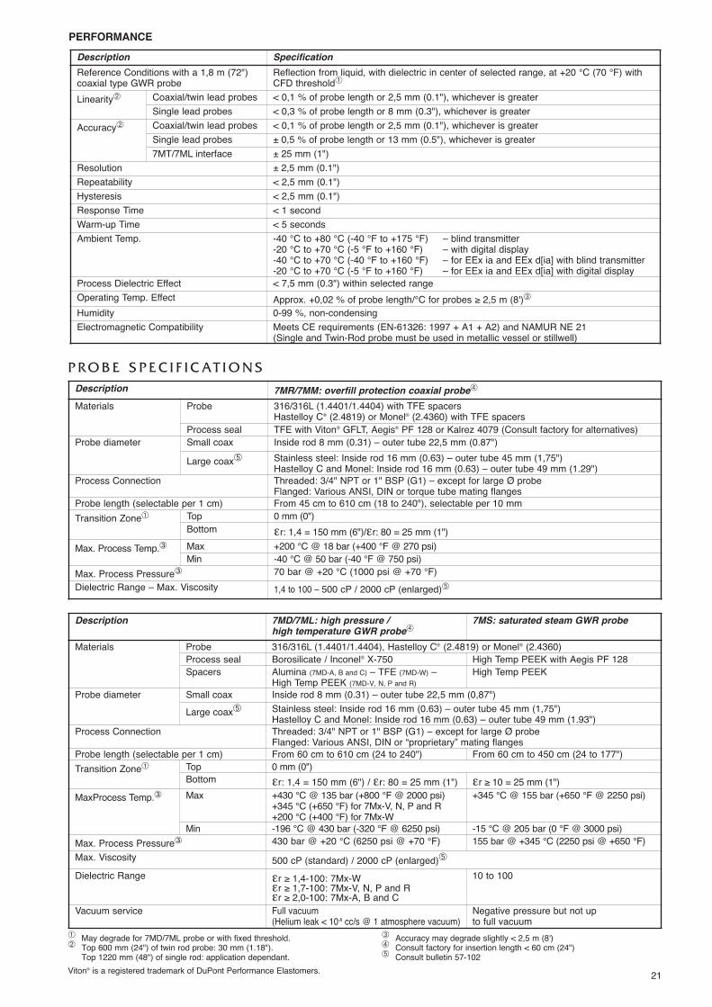
PERFORMANCE
� May degrade for 7MD/7ML probe or with fixed threshold.� Top 600 mm (24") of twin rod probe: 30 mm (1.18").
Top 1220 mm (48") of single rod: application dependant.
� Accuracy may degrade slightly < 2,5 m (8')� Consult factory for insertion length < 60 cm (24")� Consult bulletin 57-102
Description SpecificationReference Conditions with a 1,8 m (72")coaxial type GWR probe
Reflection from liquid, with dielectric in center of selected range, at +20 °C (70 °F) withCFD threshold�
Linearity� Coaxial/twin lead probes < 0,1 % of probe length or 2,5 mm (0.1"), whichever is greaterSingle lead probes < 0,3 % of probe length or 8 mm (0.3"), whichever is greater
Accuracy� Coaxial/twin lead probes < 0,1 % of probe length or 2,5 mm (0.1"), whichever is greaterSingle lead probes ± 0,5 % of probe length or 13 mm (0.5"), whichever is greater7MT/7ML interface ± 25 mm (1")
Resolution ± 2,5 mm (0.1")Repeatability < 2,5 mm (0.1")Hysteresis < 2,5 mm (0.1")Response Time < 1 secondWarm-up Time < 5 secondsAmbient Temp. -40 °C to +80 °C (-40 °F to +175 °F) – blind transmitter
-20 °C to +70 °C (-5 °F to +160 °F) – with digital display-40 °C to +70 °C (-40 °F to +160 °F) – for EEx ia and EEx d[ia] with blind transmitter-20 °C to +70 °C (-5 °F to +160 °F) – for EEx ia and EEx d[ia] with digital display
Process Dielectric Effect < 7,5 mm (0.3") within selected rangeOperating Temp. Effect Approx. +0,02 % of probe length/°C for probes ≥ 2,5 m (8')�Humidity 0-99 %, non-condensingElectromagnetic Compatibility Meets CE requirements (EN-61326: 1997 + A1 + A2) and NAMUR NE 21
(Single and Twin-Rod probe must be used in metallic vessel or stillwell)
P R O B E S P E C I F I C AT I O N SDescription 7MR/7MM: overfill protection coaxial probe�
Materials Probe 316/316L (1.4401/1.4404) with TFE spacersHastelloy C® (2.4819) or Monel® (2.4360) with TFE spacers
Process seal TFE with Viton® GFLT, Aegis® PF 128 or Kalrez 4079 (Consult factory for alternatives)Probe diameter Small coax Inside rod 8 mm (0.31) – outer tube 22,5 mm (0.87")
Large coax� Stainless steel: Inside rod 16 mm (0.63) – outer tube 45 mm (1,75")Hastelloy C and Monel: Inside rod 16 mm (0.63) – outer tube 49 mm (1.29")
Process Connection Threaded: 3/4" NPT or 1" BSP (G1) – except for large Ø probeFlanged: Various ANSI, DIN or torque tube mating flanges
Probe length (selectable per 1 cm) From 45 cm to 610 cm (18 to 240"), selectable per 10 mmTransition Zone� Top 0 mm (0")
Bottom εr: 1,4 = 150 mm (6")/εr: 80 = 25 mm (1")Max. Process Temp.� Max +200 °C @ 18 bar (+400 °F @ 270 psi)
Min -40 °C @ 50 bar (-40 °F @ 750 psi)Max. Process Pressure� 70 bar @ +20 °C (1000 psi @ +70 °F)Dielectric Range – Max. Viscosity 1,4 to 100 – 500 cP / 2000 cP (enlarged)�
Description 7MD/7ML: high pressure /high temperature GWR probe�
7MS: saturated steam GWR probe
Materials Probe 316/316L (1.4401/1.4404), Hastelloy C® (2.4819) or Monel® (2.4360)Process seal Borosilicate / Inconel® X-750 High Temp PEEK with Aegis PF 128Spacers Alumina (7MD-A, B and C) – TFE (7MD-W) –
High Temp PEEK (7MD-V, N, P and R)High Temp PEEK
Probe diameter Small coax Inside rod 8 mm (0.31) – outer tube 22,5 mm (0,87")Large coax� Stainless steel: Inside rod 16 mm (0.63) – outer tube 45 mm (1,75")
Hastelloy C and Monel: Inside rod 16 mm (0.63) – outer tube 49 mm (1.93")Process Connection Threaded: 3/4" NPT or 1" BSP (G1) – except for large Ø probe
Flanged: Various ANSI, DIN or “proprietary” mating flangesProbe length (selectable per 1 cm) From 60 cm to 610 cm (24 to 240") From 60 cm to 450 cm (24 to 177")Transition Zone� Top 0 mm (0")
Bottom εr: 1,4 = 150 mm (6") / εr: 80 = 25 mm (1") εr ≥ 10 = 25 mm (1")MaxProcess Temp.� Max +430 °C @ 135 bar (+800 °F @ 2000 psi)
+345 °C (+650 °F) for 7Mx-V, N, P and R+200 °C (+400 °F) for 7Mx-W
+345 °C @ 155 bar (+650 °F @ 2250 psi)
Min -196 °C @ 430 bar (-320 °F @ 6250 psi) -15 °C @ 205 bar (0 °F @ 3000 psi)Max. Process Pressure� 430 bar @ +20 °C (6250 psi @ +70 °F) 155 bar @ +345 °C (2250 psi @ +650 °F)Max. Viscosity 500 cP (standard) / 2000 cP (enlarged)�Dielectric Range εr ≥ 1,4-100: 7Mx-W
εr ≥ 1,7-100: 7Mx-V, N, P and Rεr ≥ 2,0-100: 7Mx-A, B and C
10 to 100
Vacuum service Full vacuum(Helium leak < 10-8 cc/s @ 1 atmosphere vacuum)
Negative pressure but not up to full vacuum
Viton® is a registered trademark of DuPont Performance Elastomers. 21
Description 7MF: standard single rod 7MJ: HTHP single rod
MaterialsProbe
316/316L (1.4401/1.4404), Monel® (2.4360),Hastelloy C® (2.4819) or PFA insulated 316/316L(1.4401/1.4404)
316/316L (1.4401/1.4404), Monel® (2.4360) orHastelloy C® (2.4819)
Process seal TFE with Viton® GFLT or Kalrez 4079 (Consult factory for alternatives) PEEK with Aegis PF 128
Probe diameter Bare: 13 mm (0.50") - PFA coated: 16 mm (0.625") Bare: 13 mm (0.50")
Mounting See mounting considerations on page 15Process Connection Threaded: 2" NPT or 2" BSP (G2) – Flanged: Various ANSI or EN/DINProbe length From 600 mm to 6100 mm (24" to 240") (selectable per 1 cm)Blocking distance (top) 120 mm up to 910 mm (4.8" up to 36") - depending probe length (adjustable)Transition Zone� (bottom) εr ≥ 10: 25 mm (1")
Process Temp. Max +150 °C @ 27 bar (+300 °F @ 400 psi) ambient +315 °C @ 110 bar (+600 °F @ 1600 psi)Min -40 °C @ 50 bar (-40 °F @ 750 psi) – 13,7 bar (200 psi) for 7MF-F
Max Process Pressure 70 bar @ +20 °C (1000 psi @ +70 °F) 207 bar @ +20 °C (3000 psi @ +70 °F)Max Viscosity 10.000 cP – consult factory in case of agitation/turbulenceDielectric Range εr 10-100 (depending installation conditions, down to εr ≥ 1,9) – liquidsMechanical load Not applicablePulldown force Not applicable
Media coating Max error of 10 % of coated length. % Error is related to dielectric of medium, thickness of coating andcoated probe length above level.
Viton® is a registered trademark of DuPont Performance Elastomers.
22
� Transition Zone (zone with reduced accuracy) is dielectric dependent; εr = dielectric permitivity. It is recommended to set 4-20 mA signal out-side transition zones.
� Bridging is defined as continuous accumulation of material between theprobe elements.
� See tables at page 23.� Consult factory for insertion length < 60 cm (24")� Consult bulletin 57-102
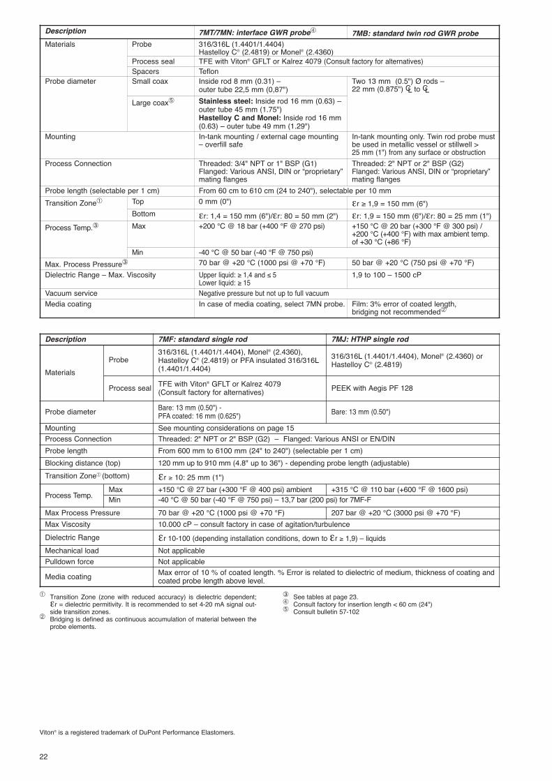
Description 7MT/7MN: interface GWR probe� 7MB: standard twin rod GWR probeMaterials Probe 316/316L (1.4401/1.4404)
Hastelloy C® (2.4819) or Monel® (2.4360)Process seal TFE with Viton® GFLT or Kalrez 4079 (Consult factory for alternatives)Spacers Teflon
Probe diameter Small coax Inside rod 8 mm (0.31) – outer tube 22,5 mm (0,87")
Two 13 mm (0.5") Ø rods –22 mm (0.875") CL to CL
Large coax� Stainless steel: Inside rod 16 mm (0.63) –outer tube 45 mm (1.75")Hastelloy C and Monel: Inside rod 16 mm(0.63) – outer tube 49 mm (1.29")
Mounting In-tank mounting / external cage mounting – overfill safe
In-tank mounting only. Twin rod probe mustbe used in metallic vessel or stillwell >25 mm (1") from any surface or obstruction
Process Connection Threaded: 3/4" NPT or 1" BSP (G1)Flanged: Various ANSI, DIN or “proprietary”mating flanges
Threaded: 2" NPT or 2" BSP (G2)Flanged: Various ANSI, DIN or “proprietary”mating flanges
Probe length (selectable per 1 cm) From 60 cm to 610 cm (24 to 240"), selectable per 10 mmTransition Zone� Top 0 mm (0") εr ≥ 1,9 = 150 mm (6")
Bottom εr: 1,4 = 150 mm (6")/εr: 80 = 50 mm (2") εr: 1,9 = 150 mm (6")/εr: 80 = 25 mm (1")Process Temp.� Max +200 °C @ 18 bar (+400 °F @ 270 psi) +150 °C @ 20 bar (+300 °F @ 300 psi) /
+200 °C (+400 °F) with max ambient temp.of +30 °C (+86 °F)
Min -40 °C @ 50 bar (-40 °F @ 750 psi)Max. Process Pressure� 70 bar @ +20 °C (1000 psi @ +70 °F) 50 bar @ +20 °C (750 psi @ +70 °F)Dielectric Range – Max. Viscosity Upper liquid: ≥ 1,4 and ≤ 5
Lower liquid: ≥ 151,9 to 100 – 1500 cP
Vacuum service Negative pressure but not up to full vacuumMedia coating In case of media coating, select 7MN probe. Film: 3% error of coated length,
bridging not recommended�
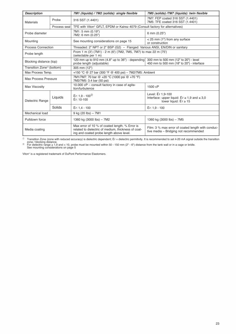
Description 7M1 (liquids) / 7M2 (solids): single flexible 7M5 (solids) /7M7 (liquids): twin flexible
Materials Probe 316 SST (1.4401) 7M7: FEP coated 316 SST (1.4401)7M5: TFE coated 316 SST (1.4401)
Process seal TFE with Viton® GFLT, EPDM or Kalrez 4079 (Consult factory for alternatives)
Probe diameter 7M1: 5 mm (0.19")7M2: 6 mm (0.25") 6 mm (0.25")
Mounting See mounting considerations on page 15 < 25 mm (1") from any surface or construction
Process Connection Threaded: 2" NPT or 2" BSP (G2) – Flanged: Various ANSI, EN/DIN or sanitaryProbe length From 1 m (3') (7M1) - 2 m (6') (7M2, 7M5, 7M7) to max 22 m (75')
(selectable per 1 m)Blocking distance (top) 120 mm up to 910 mm (4.8" up to 36") - depending
probe length (adjustable)300 mm to 500 mm (12" to 20") - level450 mm to 500 mm (18" to 20") - interface
Transition Zone� (bottom) 305 mm (12")Max Process Temp. +150 °C @ 27 bar (300 °F @ 400 psi) – 7M2/7M5: AmbientMax Process Pressure 7M1/7M7: 70 bar @ +20 °C (1000 psi @ +70 °F)
7M2/7M5: 3.4 bar (50 psi)Max Viscosity 10.000 cP – consult factory in case of agita-
tion/turbulence 1500 cP
Dielectric RangeLiquids εr: 1,9 - 100�
εr: 10-100Level: εr 1,9-100Interface: upper liquid: εr ≥ 1,9 and ≤ 3,0
lower liquid: εr ≥ 15Solids εr: 1,4 - 100 εr: 1,9 - 100
Mechanical load 9 kg (20 lbs) – 7M1Pulldown force 1360 kg (3000 lbs) – 7M2 1360 kg (3000 lbs) – 7M5
Media coatingMax error of 10 % of coated length. % Error isrelated to dielectric of medium, thickness of coat-ing and coated probe length above level.
Film: 3 % max error of coated length with conduc-tive media – Bridging not recommended
� Transition Zone (zone with reduced accuracy) is dielectric dependent; εr = dielectric permitivity. It is recommended to set 4-20 mA signal outside the transitionzone / blocking distance.
� For dielectric range ≥ 1,9 and < 10, probe must be mounted within 50 - 150 mm (2" - 6") distance from the tank wall or in a cage or bridle. See mounting considerations on page 5
Viton® is a registered trademark of DuPont Performance Elastomers.
23

QUALITY ASSURANCE - ISO 9001:2000THE QUALITY ASSURANCE SYSTEM IN PLACE AT MAGNETROL GUARANTEES THE HIGHEST LEVEL OF QUALITY DURING THE DESIGN,THE CONSTRUCTION AND THE SERVICE OF CONTROLS.OUR QUALITY ASSURANCE SYSTEM IS APPROVED AND CERTIFIED TO ISO 9001:2000 AND OUR TOTAL COMPANY IS COMMITTED TOPROVIDING FULL CUSTOMER SATISFACTION BOTH IN QUALITY PRODUCTS AND QUALITY SERVICE.
PRODUCT WARRANTYALL MAGNETROL ELECTRONIC AND ULTRASONIC LEVEL CONTROLS ARE WARRANTED FREE OF DEFECTS IN MATERIALS AND WORK-
MANSHIP FOR ONE FULL YEAR FROM THE DATE OF ORIGINAL FACTORY SHIPMENT. IF RETURNED WITHIN THE WARRANTY PERIOD; AND, UPON FACTORY INSPEC-TION OF THE CONTROL, THE CAUSE OF THE CLAIM IS DETERMINED TO BE COVERED UNDER THE WARRANTY; THEN, MAGNETROL INTERNATIONAL WILL REPAIR ORREPLACE THE CONTROL AT NO COST TO THE PURCHASER (OR OWNER) OTHER THAN TRANSPORTATION. MAGNETROL SHALL NOT BE LIABLE FOR MISAPPLICATION, LABOR CLAIMS, DIRECT OR CONSEQUENTIAL DAMAGE OR EXPENSE ARISING FROM THE INSTALLATIONOR USE OF THE EQUIPMENT. THERE ARE NO OTHER WARRANTIES EXPRESSED OR IMPLIED, EXCEPT, SPECIAL WRITTEN WARRANTIES COVERING SOME MAGNETROLPRODUCTS.
:2000
BENELUX Heikensstraat 6, 9240 Zele, België -BelgiqueFRANCE Tél. +32 (0)52.45.11.11 • Fax. +32 (0)52.45.09.93 • E-Mail: [email protected] Alte Ziegelei 2-4, D-51491 Overath
Tel. +49 (0)2204 / 9536-0 • Fax. +49 (0)2204 / 9536-53 • E-Mail: [email protected] C-20 Community Centre, Janakpuri, New Delhi - 110 0058
Tel. +91 (11) 41661840 • Fax +91 (11) 41661843 • E-Mail: [email protected] Via Arese 12, I-20159 Milano
Tel. +39 02 607.22.98 (R.A.) • Fax. +39 02 668.66.52 • E-Mail: [email protected]. DAFZA Office 5EA 722 • PO Box 293671 • Dubai
Tel. +971-4-6091735 • Fax +971-4-6091736 • E-Mail: [email protected] Unit 1 Regent Business Centre, Jubilee Road Burgess Hill West Sussex RH 15 9TLKINGDOM Tel. +44 (0)1444 871313 • Fax +44 (0)1444 871317 • E-Mail: [email protected]
www.magnetrol.com
BULLETIN N°: BE 57-101.17EFFECTIVE: MARCH 2009SUPERSEDES: April 2008UNDER RESERVE OF MODIFICATIONS
OUR NEAREST REPRESENTATIVE
T E M P E R AT U R E - P R E S S U R E R AT I N G F O R E C L I P S E P R O B E S E A L S
Process Temperature (°C)
Process Pressure (bar)
0 10 20 30 40 50
60 70
-40 -20 0 20 40 60 80 100 120 140 160 180 200
7M1/7M7/7MF GWR probes7MB GWR probes
Process Temperature (°C)
Process Pressure (bar)
0 50
100 150 200 250
-100 -50 0 50 100 150 200 250 300 350 400 450
300 350
400450500
-150
7MD/7ML GWR probe7MS/7MJ GWR probes (7MJ max +315 °C)
down to -196 °C @ 430 bar
Process Temperature (°C)
Process Pressure (bar)
0 10 20 30 40 50
60 70
-40 -20 0 20 40 60 80 100 120 140 160 180 200
7MR/7MT/7MM/7MN GWR probes
Process Temperature (°C)
Process Pressure (bar)
0 50
100 150 200 250
-100 -50 0 50 100 150 200 250 300 350 400 450
300 350
-150
7EK: top/bottom GWR probe: max +260 °C for con-ductive and non conductive liquids7EK: top/bottom GWR probe: max +320 °C for con-ductive liquids only