ece 440 lecture 37 :...
TRANSCRIPT

ECE 440Lecture 37 : MOS-II
Class Outline:
•Ideal MOS Capacitor – Quantitative•MOS Capacitance

• How can I describe the electrostatics of a MOS capacitor?
• How do I extract the important quantities from the C-V measurements?
M. J. Gilbert ECE 440 – Lecture 37 04/26/1 0
Things you should know when you leave…
Key Questions

M. J. Gilbert ECE 440 – Lecture 37 04/26/1 0
Ideal MOS Capacitor - QualitativeWhat happens if we change the doping of the substrate?

M. J. Gilbert ECE 440 – Lecture 37 04/26/1 0
Ideal MOS Capacitor - Qualitative
• Define a potential qφS which determines how much band bending there is at the surface.
• When qφS = 0 we are in flat band condition.
• When qφS < 0 we have hole accumulation at the surface.
• When qφS > 0 we have electron accumulation at the surface.
• When qφS > qφF we have inversion at the surface.
• Surface should be as strongly n-type as the body is p-type.
When VG is large enough, the surface is inverted.The n-type surface that forms as a result of the applied electric field is the key to transistor operation!
FbulkIF EEq −=φ
==
i
AbF
INVS n
NqTk ln22φφ
==
i
DbF
INVS n
NqTk ln22φφ

M. J. Gilbert ECE 440 – Lecture 37 04/26/1 0
Ideal MOS Capacitor - QuantitativeLet’s begin to put numbers to our analysis…We want to understand the variation of the potential as we move from the surface to the bulk of our semiconductor.
We know that it vanishes as we proceed deeper into the semiconductor…
That’s fine…but we are very interested in what is happening at the surface of our semiconductor-oxide interface.
The surface potential is related to the voltages we apply, but there is also a potential which is related to the semiconductor doping. p-type
n-type

M. J. Gilbert ECE 440 – Lecture 37 04/26/1 0
Ideal MOS Capacitor - QuantitativeLike we saw earlier, since there is no current, we can use simple relations for doping density…
We may now solve for the Fermi potential…
We will make lots of use of both the surface and Fermi potential.
Now we want to use them to determine the bias state…φs = 0 Flat band
Depletion inversion φs = 2φf
accumulated
depleted

M. J. Gilbert ECE 440 – Lecture 37 04/26/1 0
Ideal MOS Capacitor - QuantitativeAccumulation and depletion may be represented by delta functions, but what about other times?
Let’s assume that we are dealingwith a p-type semiconductor andwrite down the depletionapproximation solution to thecharge density…
Now we can reduce Poisson’s equation to something more tractable:Integrate
Electric fieldIntegrate
Potential

M. J. Gilbert ECE 440 – Lecture 37 04/26/1 0
Ideal MOS Capacitor - QuantitativeFor the most part thus far, we have been describing the biasing state in terms of the surface potential…
The problem is that we can’t control the surface potential, but we can control the gate voltage. So we must know the relationship between the gate voltage and the surface potential.
we can simplify
in bulkNow represent the voltage dropped across the oxide in terms of the surface potential…
Ideal oxide
Oxide thickness
M. J. Gilbert ECE 440 – Lecture 37 04/26/1 0
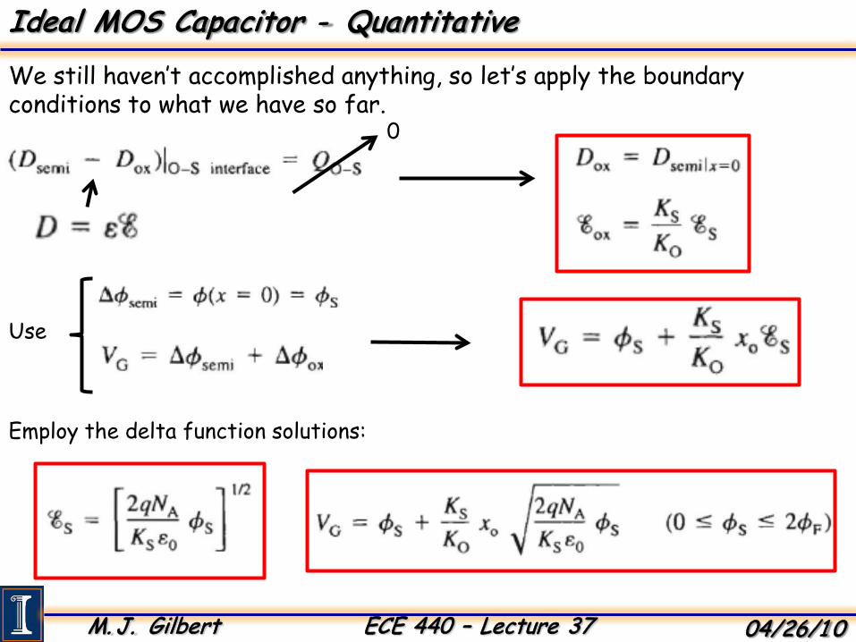
Ideal MOS Capacitor - QuantitativeWe still haven’t accomplished anything, so let’s apply the boundary conditions to what we have so far.
0
Use
Employ the delta function solutions:

M. J. Gilbert ECE 440 – Lecture 37 04/26/1 0
Ideal MOS Capacitor - QuantitativeIs there another way to obtain physical information from this structure?
Electron and hole concentrations are related to the potential…
Tkq
iTkEE
ib
F
b
IF
enennφ−−
==0
We then know the electron (hole) concentration at any x…
( )
Tkq
Tkq
Tkq
b
bb
F
epp
enennφ
φφφ
−
−−
=
==
0
00Electrons
Holes
But we still need the potential, how do we get it?
Poisson EquationTotal Charge Density

M. J. Gilbert ECE 440 – Lecture 37 04/26/1 0
Ideal MOS Capacitor - QuantitativeUse Poisson equation and total charge density to get the total charge…
Substitute in our knowledge of carrier concentrations and we get…
−−
−−=
∂∂
∂∂
=∂∂
−
11 002
2Tk
qTk
q
S
bb enepqxxx
φφ
εφφ
Electric Field
Integrate from the bulk (where the bands are flat, there are no electric fields, and the doping alone sets the carrier concentrations) towards the surface…
∫∫
−−
−−=
∂∂
∂∂
−φ φφφ
φε
φφ
000
0
11 denepqx
dx
Tkq
Tkq
S
dxd
bb
We now integrate and examine the result at the surface (x = 0) where the perpendicular electric field becomes…
Debye length – distance at which charge fluctuations are screened out to look like neutral entities.

M. J. Gilbert ECE 440 – Lecture 37 04/26/1 0
Ideal MOS Capacitor - QuantitativeSo what does the surface charge density look like?
• At φs = 0 there is no space charge.
• When φs is negative we accumulate majority holes at the surface.
• When φs is positive initially the linear term in the electric field solution dominates as a result of the exposed, immobile dopants.
• Depletion extends over several hundred nm until we reach strong inversion and the exponential field term dominates.
sssQ ξε−=Use Gauss’ Law to find the charge:

M. J. Gilbert ECE 440 – Lecture 37 04/26/1 0
MOS CapacitanceLet’s now examine how the capacitance changes with applied bias…
In accumulation:• The capacitance is huge.• Structure acts like a
parallel plate capacitor piling holes up at the surface.
The capacitance depends on the voltage…
MOS Capacitor is the series combination of the oxide and the voltage dependent semiconductor capacitances.

M. J. Gilbert ECE 440 – Lecture 37 04/26/1 0
And how the capacitance behaves as we vary the bias…
In depletion:• Capacitance decreases as W grows until inversion is reached.• Charge in depletion layer of MOS capacitor increases as ~ (φS)1/2 so depletion
capacitance decreases as the inverse.• If signal applied to make measurement is too fast, inversion layer carriers
can’t respond and do not contribute.• Slowly varying signals allow time for minority carriers to be generated, drift
across depletion region, or recombine.• Majority carriers in the accumulation region respond much faster.
The surface becomes depleted and the depletion layer capacitance needs to be added in…
Total capacitance:
MOS Capacitance

M. J. Gilbert ECE 440 – Lecture 37 04/26/1 0
So let’s summarize what should be happening in depletion…
MOS Capacitance
We have an oxide capacitance:
In series with the semiconductor capacitance:

M. J. Gilbert ECE 440 – Lecture 37 04/26/1 0
What happens when we bias the MOS capacitor into the inversion regime…
MOS Capacitance
We have two responses:
LF
HF
•R-G can follow signal. •Charge changes close to oxide.
•R-G can’t follow signal. •Charge doesn’t change from dc.

M. J. Gilbert ECE 440 – Lecture 37 04/26/1 0
Remember that we can keep things simple by using the delta depletion approximation.
MOS Capacitance
Charges close to oxideWrite down all capacitances:
•Given a set of parameters, we can find the oxide capacitance and the maximum depletion width.
•What about surface potential and it’s relation to gate voltage?

M. J. Gilbert ECE 440 – Lecture 37 04/26/1 0
• Workfunctiondifferences can significantly affect VT and other properties.
• The difference is always negative and is most negative for heavily p-type Si.
• This is reminiscent of the work on the metal-semiconductor contacts.
φms = φm - φsReal surfaces have workfunction differences…
Φms< 0
Tends to decrease the threshold voltage…
MOS Capacitance

M. J. Gilbert ECE 440 – Lecture 37 04/26/1 0
So what does this mean for our band diagrams…
•The negative workfunction difference causes the bands to be pulled down farther in equilibrium.•To achieve flatband conditions, we must apply a positive voltage to overcome the inherent bending in the bands,•Clearly, this behavior will lead to shifts in the threshold voltage.
MOS Capacitance

M. J. Gilbert ECE 440 – Lecture 37 04/26/1 0
Can’t we get more information from the capacitance-voltage data?
• Remember: that majority carriers respond faster to changes in VG and minority carriers respond more slowly
We can get a lot of information from the capacitance-voltage (C-V) data.
•Insulator thickness•Substrate doping•Threshold voltage
Shape of the C-V curve depends on the type of substrate doping.
•P-type:
•High frequency capacitance: large for negative gate bias and small for positive bias
•Low frequency C-V curve: as gate bias becomes more positive (or negative) C goes down slowly in depletion and raises quickly in inversion
MOS Capacitance

M. J. Gilbert ECE 440 – Lecture 37 04/26/1 0
Let’s find the insulator thickness and the depletion width…
• By using the capacitance (Ci = εi/d) in accumulation or strong inversion at low-frequency will give us the insulator thickness.
• The capacitance Cmin is the series combination of the capacitance Ci and the minimum depletion capacitance Cdmin = εs/Wm.
• This will give us the maximum depletion width. This is a transcendental equation
which requires a numerical solution. It’s solution gives NA in terms of Cdmin.
MOS Capacitance

M. J. Gilbert ECE 440 – Lecture 37 04/26/1 0
Once we know the substrate doping, we can find the flatbandcapacitance…
• The overall MOS FB capacitance CFB is the series combination of Cdebye and Ci. From these values we can determine VFBthe corresponds to CFB.
The flatband capacitance is determined from the Debye length capacitance…
The Debye length depends on the doping…
MOS Capacitance

M. J. Gilbert ECE 440 – Lecture 37 04/26/1 0
We now have all of the ingredients to calculate the threshold voltage…
VT does not correspond exactly to Cdmin but rather to point 4 which is located at Ci+ 2 Cdmin.
Why ??
Because change of charge in semiconductor is the sum of the change in the depletion charge and the mobile inversion charge which are equal at onset of strong inversion.
MOS Capacitance
M. J. Gilbert ECE 440 – Lecture 37 04/26/1 0
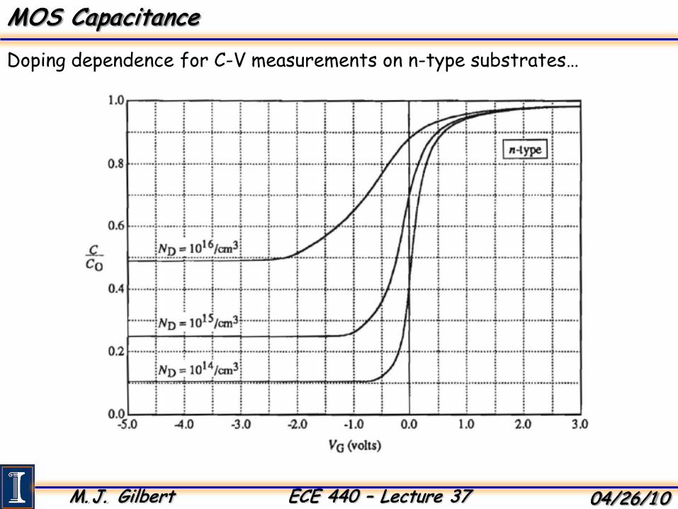
Doping dependence for C-V measurements on n-type substrates…
MOS Capacitance

M. J. Gilbert ECE 440 – Lecture 37 04/26/1 0
Doping dependence of C-V measurements on p-type substrates:
MOS Capacitance
M. J. Gilbert ECE 440 – Lecture 37 04/26/1 0
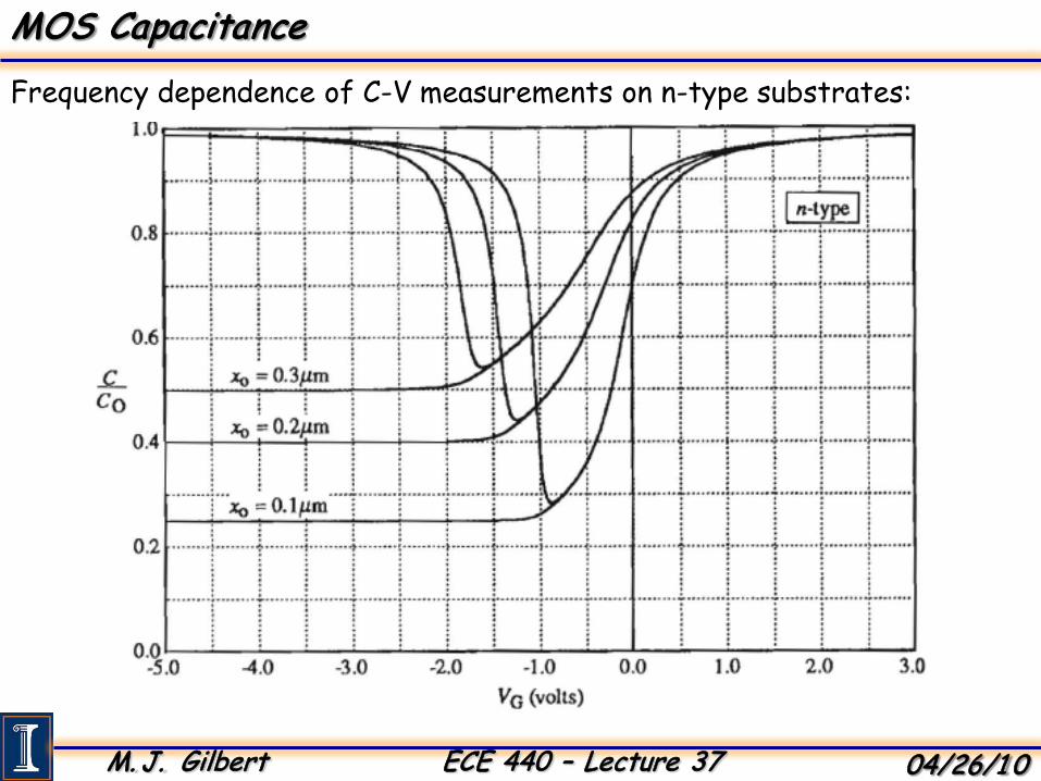
Frequency dependence of C-V measurements on n-type substrates:
MOS Capacitance