earthquakes - council on tall buildings and urban habitat · earthquakes and valuable records of...
TRANSCRIPT
Title: Control Effect of Hydraulic Dampers Installed in High-rise BuildingObserved during Earthquakes
Authors: Kan Shimizu, Senior Research Engineer, Kajima CorporationSatoshi Orui, Supervisory Research Engineer, Kajima CorporationHaruhiko Kurino, Supervisory Research Engineer, Kajima CorporationYukihiro Omika, Standing Advisor, Kajima CorporationNorihide Koshika, General Manager, Kajima Corporation
Subject: Structural Engineering
Keywords: DampingSeismicTuned Liquid Damper
Publication Date: 2008
Original Publication: CTBUH 2008 8th World Congress, Dubai
Paper Type: 1. Book chapter/Part chapter2. Journal paper3. Conference proceeding4. Unpublished conference paper5. Magazine article6. Unpublished
© Council on Tall Buildings and Urban Habitat / Kan Shimizu; Satoshi Orui; Haruhiko Kurino; Yukihiro Omika;Norihide Koshika
ctbuh.org/papers

CTBUH 8th World Congress 2008 �
Kan ShimizuKan Shimizu received the M. S. degree in civil engineering from Waseda University, Tokyo, Japan in 1997.He is currently a senior research engineer in Kobori Research Complex of Kajima Corporation. He has been involved with about twenty high rise-buildings in Japan, planning the structural control devises and conducting seismic response analyses.
Haruhiko KurinoHaruhiko Kurino received the M. S. and D.Eng. degree in structural engineering from University of Tokyo, Tokyo, Japan in 1991 and 2004, respectively.He is currently a supervisory research engineer in Kobori Research Complex of Kajima Corporation. He has studied structural control algorithms and developed hydraulic control devices, including a semi-active oil damper which has been widely used in high-rise buildings in Japan.
Control Effect of Hydraulic Dampers Installed in High-rise Building Observed during Earthquakes
Kan Shimizu1, Satoshi Orui2, Haruhiko Kurino2, Yukihiro Omika3 and Norihide Koshika4
1Senior Research Engineer, 2Supervisory Research Engineer, 3Standing Advisor, 4General Manager, Kajima Corporation KI Building 6-5-30, Akasaka, Minato-ku, Tokyo, Japan
Email: [email protected], [email protected], [email protected], [email protected], [email protected]
Abstract This paper estimates the dynamic characteristic, especially damping, of an actual high-rise building with two kinds of oil dampers, conventional passive oil dampers and semi-active switching oil dampers, from records of the building’s responses during large earthquakes. It also assesses the effect of the semi-active oil dampers by comparing the estimated damping with that predicted by a seismic design model. The building is located in Niigata prefecture, Japan, which has recently been subjected to three large earthquakes: the Mid Niigata prefecture Earthquake in 2004, the Noto Hanto Earthquake in 2007 and the Niigataken Chuetu-oki Earthquake in 2007. During these earthquakes, valuable records were obtained of the responses of the building and behavior of the semi-active oil damper. From the records, equivalent damping ratios are estimated at 6.4% to 6.7% in the transverse direction in which the semi-active oil dampers are applied and 4.3% to 4.8% in the longitudinal direction in which the passive oil dampers are applied. The high damping property of the structural controlled building is also verified. The damping provided by the semi-active oil dampers is estimated at about 5.5%, which was about 1.7 times that predicted by a seismic design model with passive oil dampers. Thus, the effect of the semi-active oil dampers is also verified.
Keywords: structural control, semi-active oil damper, damping, observed record, earthquake
Introduction In the last two decades a lot of research and
application has been carried out on structural control devices (Spencer, 2003, etc.). Recently many high-rise buildings in Japan are being equipped with some kind of structural control device. However, there are few seismic response records from buildings equipped with these device. Therefore, their effects in actual buildings in actual earthquakes have been insufficiently verified. A high-rise building with two kinds of oil dampers, semi-active and passive, recently experienced three large earthquakes and valuable records of its response and the behavior of the semi-active oil dampers were obtained. This paper reports the high damping characteristics of this building and the effects of the semi-active oil dampers.
Outline of high-rise building The building was constructed in 2003, in Niigata
prefecture. Figure 1 shows its exterior. It is 140m high and has 31 floors above ground and one underground. The lower floors are used as offices and the upper floors are used as hotel, as shown in Figure 2. Columns are concrete-filled steel tubes and the beams are steel. Oil dampers are mainly designed to reduce building responses under severe earthquakes. However, uncomfortable transverse vibrations were expected during strong winds because of its slender shape. Therefore, the
dampers in the transverse direction were upgraded to semi-active oil dampers, which also work for very small vibrations and absorb twice as much energy as conventional oil dampers.
Figure 2. Section Figure 1. Exterior of the building
Semi-active Oil DamperPassive Oil Damper
5F
46.4m
23m
1~5F 1~4F
1~8F1~8F
1~10F
1~19
F
1~19
F
Figure 3. Plan
Hotel
Office
Semi-active Oil Damper

CTBUH 8th World Congress 2008 �
Figure 3 shows the distribution of the dampers. 72 semi-active oil dampers are set in the transverse direction and 40 passive oil dampers are set in the longitudinal direction.
Outline of semi-active oil damper Figure 4 shows the semi-active oil damper installed
in the building. One of the features of this damper is that the whole system which consists of a controller and an oil damper equipped with sensors is closed as shown in Figure 4. This makes it as easy to use this semi-active oil damper as it is use to a conventional oil damper. Table 1shows its specifications.
Table 1. Specifications of semi-active oil damper Item Specification
Maximum design force Fmax 1,500kN Relief force FR 1,300kN
Maximum piston stroke 120mm Stiffness kd 500MN/m
Size 370mm,1435mm Power consumption Approximately 50W
Oil dampers are usually installed in the inter-story spaces of buildings with braces as shown in Figure 5.Their mechanical model is described as a Maxwell model. Under the constraint of the Maxwell model, a conventional passive oil damper with a linear damping coefficient behaves like a spring when the damping coefficient is too large and doesn’t generate any force when it is too small. Therefore, there is an optimum damping coefficient that produces the maximum energy absorption capacity for the passive oil damper. On the other hand, the semi-active oil damper’s control law maximizes the energy absorption capacity under the constraint of the Maxwell model by switching the damping coefficient, as described in Kurino et al. (2003). Figure 6 show the behavior of the Maxwell model and its elements under this control law. The damping coefficient (C(t)) is usually kept large (Cmax). When vibration starts C(t) is kept to Cmax from point A to B, so the dashpot doesn’t move and the spring accumulates energy. At point B, at which the velocity changes direction, C(t) is
changed to a very small value (Cmin) and the dashpot absorbs the energy accumulated in the spring. When the force decreases to point C, C(t) is changed to Cmax again and the damper continues this cycle. The force-displacement relation of a semi-active oil damper under this control law is shown in Figure 7. The force-displacement relation of a passive oil damper with an optimum damping coefficient is also shown in Figure 7. These areas show the energy absorption capacity of the damper. The semi-active oil damper can absorb twice as much energy as the passive oil damper.
Damper characteristics and performance have been verified through full-scale device tests (Kurino et al., 2003), and forced vibration tests (Tagami et al., 2002, Shimizu et al., 2004). It is now being applied or planned for more than 20 buildings and this number will increase.
Observed response during earthquake Acceleration sensors were set on the roof floor
mainly to observe the building’s response under strong winds such as typhoons. The 5th floor semi-active oil damper’s force and stroke were also observed to check its behavior. On October 23 2004, the building was subjected to the Mid-Niigata Prefecture Earthquake whose magnitude was 6.8 and epicentral distance was about 73km. In order to estimate the dynamic characteristics of the building from records of after
x
2k
k
-2k
F
Cmax Cmin
Cmin Cmax Passive oil damper with optimum C
Semi-active oil damper
Figure 7. Force-displacement relation of dampers under harmonic excitation
x
F
k
A
B
C
D
xk
F
A
B
C
D
Cm ax Cm in
Cm ax
F
-F0
F0A
B
C
D
Cm ax Cm in
Cm ax
FB
(a)Maxwell model (b)Spring element (c)Dashpot elementFigure 6. Behavior of semi-active oil damper
Figure 4. Installed semi-active oil damper
Column
Damper
Beam
Brace
Figure 5. Mechanical model of oil damper installed in a building
Controller
Oil Damper
Brace, Damper Damper

CTBUH 8th World Congress 2008 �
shocks, an acceleration sensor was quickly added to the first basement floor. Records of after shocks in November 8 were thus obtained. There were two more large earthquakes in 2007. The first was the Noto Hanto Earthquake, whose magnitude was 6.9 and epicentral distance was about 220 km. The next was the Niigataken Chuetu-oki Earthquake, whose magnitude was 6.8 and epicentral distance was 57 km. During this earthquake, the maximum damper force reached 640kN, which was the maximum force of this damper in an actual building.
These records are very valuable because such large responses of a structural controlled building and a
structural control device in an actual building are rare. Figure 8 shows the records during the Niigataken Chuetu-oki Earthquake. The force-displacement relation shown in Figure 8(e) shows the typical parallelogram shape produced by this control law.
Table 2 shows the maximum acceleration of the roof floor and the first basement floor and the maximum force of the semi-active oil damper. Figure 9 shows the location of the building and the epicenters.
Table 2. Maximum acceleration of records
Earthquake B1F
Long. (cm/s2)
B1FTran.
(cm/s2)
RF Long. (cm/s2)
RFTran.
(cm/s2)
Force(kN)
1 Mid Niigata (main) - - 50.8 74.4 262
2 Mid Niigata (after) 7.6 4.0 18.1 14.7 111
3 Noto Hanto 11.1 8.8 28.9 38.6 127 4 Chuetu-oki 24.0 20.0 46.8 99.6 640
Estimate of building’s dynamic characteristics In this section, dynamic characteristics such as
natural frequency and equivalent damping ratio are estimated. In particular, damping is discussed and the effect of dampers is verified. Only the first mode, which is the dominant vibration mode of the building, is considered.
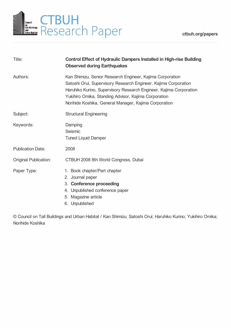
Before discussing damping during earthquakes, damping during microtremors is demonstrated, because the vibration level of microtremors is small enough to neglect the effect of dampers. Equivalent damping ratios of the building during microtremors were estimated by the Random Decrement (RD) technique (Tamura et al., 1993). Time histories of free vibrations obtained by the RD technique are shown in Figure 10. Estimated damping ratios were 0.97% in the transverse direction and 1.1% in the longitudinal direction.
Figure 9. Location of building and epicenters
0 100 200 300 400 500 600(sec)
-100
0
100
Acc
.(cm
/s2 )
(a) Roof floor acceleration (Longitudinal direction)
0 100 200 300 400 500 600(sec)
-100
0
100
Acc
.(cm
/s2 )
(b) Roof floor acceleration (Transverse direction)
0 100 200 300 400 500 600(sec)
-100
0
100
Acc
.(cm
/s2 )
(c) First basement floor acceleration (Longitudinal direction)
0 100 200 300 400 500 600(sec)
-100
0
100
Acc.
(cm
/s2 )
(d) First basement floor acceleration (Transverse direction)
(e) Force-stroke relation of 5th floor semi-active oil damper Figure 8. Records of the Niigataken Chuetu-oki earthquake in 2007
Building
3 14
CTBUH 8th World Congress 2008 �
On the basis of damping of conventional steel structures shown in Satake, 2003, these results were inferred as damping without dampers.
Next, the dynamic characteristics under earthquake vibrations are estimated. First, the time history of the roof floor acceleration is filtered to extract the first vibration mode. Then a Single Degree of Freedom (SDOF) system that makes the mean-square error the smallest is identified as shown in the following equation
min))()((
)()()(4)(
211
0
112
dttxtX
tXtxtxhftx
RFRFT
FB (1)
where x(t) is the response of a SDOF system, h is the damping ratio of a SDOF system, f is the natural frequency of a SDOF system, FBX 11 is the filtered acceleration record at the first basement floor, T is the duration of the earthquake, RFX1 is the filtered acceleration record at the roof floor, and RF1 is a first mode participation function at the roof floor, for which the participation factor of the seismic design model shown in Figure 14 is used. As a result, the natural period and the damping ratio of the SDOF system are identified as those of the building.
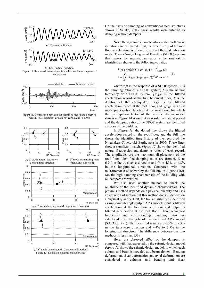
In Figure 11, the dotted line shows the filtered acceleration record at the roof floor, and the full line shows the identified time history of the record of the Niigataken Chuetu-oki Earthquake in 2007. These lines show a significant match. Figure 12 shows the identified natural frequencies and damping ratios of each record. The amplitudes are the maximum displacement of the roof floor. Identified damping ratios are from 6.4% to 6.7% in the transverse direction and from 4.3% to 4.8% in the longitudinal direction. Compared with the microtremor case shown by the full line in Figure 12(c), (d), the high damping characteristic of the building with oil dampers are verified.
We also used another method to check the reliability of the identified dynamic characteristics. The previous method depends on a physical quantity and uses an equation of motion but this method doesn’t depend on a physical quantity. First, the transmissibility is identified as single-input-single-output ARX model: input is filtered acceleration at the first basement floor and output is filtered acceleration at the roof floor. Then the natural frequency and corresponding damping ratio are calculated from the pole of the identified ARX model ( AFAK, 1991). The identified results are 6.3% to 7.3% in the transverse direction and 4.4% to 5.5% in the longitudinal direction. The difference between the two methods is less than 15%.
Here, the observed effect of the dampers is compared with that expected by the seismic design model. Figure 13 shows the seismic design model, in which each column and beam is modeled as a beam element. Bending deformation, shear deformation and axial deformation are considered at columns and bending and shear
0 10 20 30RF Disp.(cm)
0
0.1
0.2
0.3
0.4
Freq
.(Hz)
0 10 20 30RF Disp.(cm)
0
0.1
0.2
0.3
0.4
Freq
.(Hz)
(a) 1st mode natural frequency (b) 1st mode natural frequency (Longitudinal direction) (transverse direction)
0 10 20 30RF Disp.(cm)
0
0.02
0.04
0.06
0.08
0.1
Dam
pig
Rat
io
(c) 1st mode damping ratio (Longitudinal direcrion)
0 10 20 30RF Disp.(cm)
0
0.02
0.04
0.06
0.08
0.1
Dam
ping
Rat
io
(d) 1st mode damping ratio (transverse direcrion) Figure 12. Estimated dynamic characteristics
0 100 200 300(sec)
-100
0
100
Acc
.(cm
/s2 )
Identified Observed record
Figure 11. Comparison between the identified record and observed record (The Niigataken Chuetu-oki earthquake in 2007)
10 20 30
(sec)-60
0
60ΣAcc(cm/s2)
(a) Transverse direction
10 20 30
(sec)-60
0
60
ΣAcc(cm/s2)
(b) Longitudinal direction Figure 10. Random decrement and free vibration decay response of
microtremer
h=0.97%
h=1.1%
2
3
4
2
3 4
Microtremor
Microtremor
2
3 4
2
3 4

CTBUH 8th World Congress 2008 �
deformations are considered at beams. Panel elements at which only shear deformation is considered were set at each column/beam connection. Oil dampers are modeled as a Maxwell model, described in Figure 5. Figure 14shows the mode shape of each direction.
Complex eigen value analysis was conducted to estimate damping added by passive dampers. Damping factors of dampers were set to 50MNs/m. To accurately estimate the effect of dampers, damping of the structure isn’t set. The complex eigen value analysis yielded values of 3.2% for each direction. By subtracting damping estimated during microtremors from damping estimated during earthquakes, the damping added by the dampers in an actual building is obtained. The values thus obtained were 5.4% to 5.7% in the transverse direction and 3.2% to 3.7% in the longitudinal direction. Comparison of the results verified that the damping added by the passive
dampers is almost the same as that predicted by the seismic design model and the damping added by the semi-active oil dampers are almost 1.7 times that predicted by the seismic design model with passive oil dampers. Therefore, the effect of semi-active oil dampers is clearly verified.
Additional discussion (Wind case) This section demonstrates the effect of the
semi-active oil dampers during strong winds. In 2004, 10 typhoons struck Japan. This was a record since the Japan Meteorological Agency started to take statistics in 1951. One of them, Typhoon 16, had a maximum daily wind velocity of 19.5m/s, which was recorded at Niigata Local Meteorological Observatory. This was the maximum daily wind velocity in 2004 in Niigata, and it continued for about 2 hours.
Damping in the transverse direction during this typhoon was also estimated by an RD technique as 5.3%. Figure 15 shows the force-stroke relation of the 5th floor semi-active oil damper during the typhoon. It also shows a typical parallelogram shape from a very small stroke, under 0.5mm.
Next the “without damper” time history is estimated. The absolute acceleration response, xw, without semi-active oil damper is calculated by equation (2) considering only the first mode.
iffhffiffhffifHifH
xifHifHx
w
sws
swsw
112
1
112
11
1
/2/1/2/1)()(
)()( (2)
where Hs(if) is the 1st mode transfer function with semi-active oil damper, Hw(if) is the 1st mode transfer function without damper, xs is the observed record, 1f is the 1st natural frequency, 1hs is the 1st equivalent damping ratio with semi-active oil damper, and 1hw is the 1st equivalent damping ratio without damper.
Figure 15. Force-stroke relation of 5th floor semi-active oil damper under typhoon
Results estimated by the RD technique were used as parameters: 0.30Hz for 1f, 0.053 for 1hs, and 0.097 for 1hw. Figure 16 compares the top floor acceleration time history of “Without damper” estimated by equation (2) against the observed acceleration record. Without
:1st mode :2nd mode :3rd mode
-1.5 0 1.50
10
20
30
Floor
-1.5 0 1.50
10
20
30
Floor
(a) Longitudinal direction (b) Transverse direction Figure 14. Mode shape (Participation function)
Figure 13. Seisimic design model

CTBUH 8th World Congress 2008 �
semi-active oil damper, the maximum response of the building would double and uncomfortable vibration would continue for a long time.
Conclusion Three large earthquake records were obtained from
a high-rise building equipped with semi-active oil dampers in the transverse direction and conventional passive oil dampers in the longitudinal direction. Estimated damping verified the high damping property of the building with oil dampers. Equivalent damping ratios were from 6.4% to 6.7% in the transverse direction and from 4.3% to 4.8% in the longitudinal direction. The effect of the dampers was also discussed with reference to a seismic design model. By comparing the damping ratio added by the dampers estimated from the earthquake records with that estimated from the seismic design model with passive oil dampers, it was verified that the passive oil dampers showed almost the same results as expected, and the semi-active oil dampers showed high performance in adding damping, which was about 1.7 times as large as that expected by a passive oil damper.
References SPENCER, Jr. B. F., and NAGARAJAIAH, S. (2003). State of the Art of Structural Control. Journal of Structural Engineering, ASCE, Vol. 129 No.7, pp.845-856, July 2003 KURINO, H., TAGAMI, J., SHIMIZU, K., and KOBORI, T. (2003). Switching Oil Damper with Built-in Controller for Structural Control.Journal of Structural Engineering, ASCE, Vol. 129 No.7 pp. 895-904 TAGAMI, J., KOSHIDA, H., KURINO, H., SUGIYAMA, T., SUWA, M., and MORI, F. (2002). Forced Vibration Test of an 11-story Building with Semi-active Switching Oil Damper. Proceedings of the 3rd World Conference on Structural Control, Como, Italy. April 7-11, 2002. Vol. 2 pp.75-80 SHIMIZU, K., YAMADA, T., TAGAMI, J., and KURINO, H. (2004). Vibration Tests of Actual Buildings with Semi-active Switching Oil Damper. Proceedings of the 13th World Conference of Earthquake Engineering, Vancouver, B.C., Canada, August 1-6, 2004. Paper No. 153TAMURA, Y., SASAKI, A., and TSUKAGOSHI, H. (1993). Evaluation of Damping Ratios of Randomly Excited Buildings Using the Random Decrement Technique. Journal of Struct. Constr. Engng, AIJ; 454 pp. 29-38, in Japanese SATAKE, N., SUDA, K., ARAKAWA, T., SASAKI, A., and TAMURA, Y. (2003). Damping Evaluation Using Full-Scale Data of Building in Japan. Journal of Structural Engineering, ASCE, Vol. 129 No.4, pp.470-477, April 2003
AFAK, E. (1991). Adaptive Modeling, Identification, and Control of Dynamic Structural Systems 1: Theory. Journal of Structural Engineering, ASCE, Vol.115, No.11, pp.2386-2405, November 1991
(a) “With Damper” (Observed)
(b) “Without Damper” (Simulated) Figure 16. Roof floor acceleration time history (transverse direction)