e2 and p2 improvement opportunities in secondary aluminum processing… · 2020-02-05 · e2 and p2...
TRANSCRIPT

E2 and P2 Improvement Opportunities in Secondary Aluminum Processing: A Case Study
Matthew D. Swanson, Robert A. Miller, Jonathan J. Aardsma, and Michael J. Chimack
University of Illinois at Chicago, Energy Resources Center ABSTRACT This paper will present the results of an energy assessment at a secondary aluminum plant in northern Illinois, specifically, the energy and non-energy benefits of using a new combustion technology for scrap decoating. This new technology, a variable floatation decoater (VFD), is being developed by the U.S. Department of Energy and a private engineering firm to replace the standard rotary kilns currently used for scrap decoating.
Rotary kilns have traditionally been employed in the decoating process. However, a VFD removes organics of any type from scrap aluminum and steel using less energy. High velocity gases mechanically strip off liquid organics in a low oxygen environment. The organic laden gases are then sent to an afterburner to vaporize the organics. The VFD meets the EPA’s new Clean Air Act standards for dryers, decoaters and delacquering kilns. Based on lab testing and empirical data, VFDs can reduce the energy used by the decoating process by 50% while reducing the decoating cycle by 80%. [AA2] In addition, VFDs produce the required quality of aluminum turnings in a single pass, which eliminates the need for repeating the process, thereby increasing energy savings potential. Introduction The Aluminum Industry The United States' aluminum industry is the world's largest, generating sales of approximately $39.1 billion in products and exports. [AA1] The U.S. aluminum industry operates over 300 plants in 35 states, produces more than 23 billion pounds of metal annually and employs over 145,000 people with an annual payroll of about $5 billion. [AA1] The aluminum industry is divided into two primary segments: primary aluminum processing and secondary aluminum processing. Primary aluminum processing consists of domestic production of aluminum from ore material. In 1998 primary aluminum processing accounted for 63 percent of the U.S. production (15.5 billion pounds). [AA2] Although the primary aluminum sector of the industry accounts for the majority of the total aluminum supply in the U.S., a vital contributor is the secondary aluminum industry. The secondary aluminum industry uses aluminum scrap as its principal feedstock. This scrap is metal recovered during industrial machining and fabrication and consists of machine turnings, borings, clips, and skeletons from stamping plants. The scrap is re-melted and reformed. In 1998, the secondary aluminum industry processed 4.3 million metric tons (9.4 billion pounds) of scrap and manufactured 3.4 million metric tons (7.5 billion pounds) of aluminum, approximately 37 percent of the total U.S. aluminum supply of 104 million metric tons (23 billion pounds). [AA2]

The contribution of the secondary aluminum industry, a third of total U.S. aluminum supply, becomes even more significant when placed in historical perspective. In 1972, recycled aluminum accounted for 19 percent of the nation’s total aluminum supply. [AA2] Over the next 27 years, production of recycled aluminum rose 242 percent to 3.4 million metric tons (7.5 billion pounds). Over the same period, the total U.S. aluminum supply increased just 91 percent. [AA2] These trends demonstrate that there have been concentrated efforts to increase the amount of aluminum recovered. Furthermore, the secondary aluminum industry is an essential part of the U.S. focus on energy conservation, as recycling aluminum requires only five percent of the energy that primary-ore production requires. [AA2] This significant difference in energy usage shows the true impact secondary aluminum processing can have on the industry’s energy consumption as a whole. A transfer of one unit of primary production to secondary production will result in an energy reduction of 95 percent. As more and more aluminum is processed from scrap as opposed to ore, the total energy consumed by the aluminum industry will fall. While the United States has long consumed the majority of the world’s resources, the market for aluminum and other metals in China continues to experience growth as the country continues its rapid industrial expansion. China's economic growth reached a seven-year high at 9.1 percent in 2003. [CD] China’s State Council Development Research Center, the World Bank, Asian Development Bank and Goldman Sachs Co. have all predicted that China's economy will maintain a growth rate of over 6 percent until 2010. [CIIC]
China currently consumes over 20 percent of the world’s aluminum and copper and is the world’s biggest user of steel and cement. Even allowing for a slowdown in growth rates, China is expected to account for 30 percent of global base metals demand by 2010. [CS] This continued economic expansion, coupled with China’s increasing demand for base metals, is expected to maintain aluminum’s, and hence secondary aluminum’s, long-term trend of just under 3 percent annual growth for the foreseeable future. [NRC]
For these reasons, the secondary aluminum industry will continue to be a large consumer of energy for some time to come. The worldwide requirement for aluminum, coupled with natural gas price trending, will increase the demand for new energy conservation and reduction technologies in the secondary aluminum industry. The aluminum industry has been proactive in adopting new equipment and technologies in the past several years, making significant reductions in its energy usage. In 2002 alone, the industry reduced its energy consumption by 22 percent. [AA2] The U.S. Department of Energy (DOE) has established several grant programs intended to increase the attractiveness of energy related projects. Aside from grants to manufacturing facilities, the DOE has provided millions of dollars in research grants. Several new technologies have been built and tested, such as a ceramic coating for recuperation, cogeneration from furnace exhaust and innovative furnace control mechanisms. This paper details one such innovation. Processing Secondary Aluminum at the Plant
Aluminum scrap comes from a variety of sources. "New" scrap is generated by pre-consumer sources, such as drilling and machining of aluminum castings, scrap from aluminum fabrication and manufacturing operations and aluminum bearing residual material (dross) skimmed off molten aluminum during smelting operations. "Old" aluminum scrap is material

that has been used by the consumer and discarded. Examples of old scrap include used appliances, aluminum foil, automobile and airplane parts, aluminum siding, and beverage cans. Scrap pretreatment involves sorting and processing scrap to remove contaminants and to prepare the material for smelting. Sorting and processing separates the aluminum from other (ferrous) metals, dirt, oil, plastics, and paint. Pretreatment cleaning processes are based on mechanical and pyrometallurgical (drying) techniques. Once a facility is ready to process scrap metal, it is first transported to a shredder, where it is reduced to a manageable size. The material leaving the shredder is called “turnings.” After the shredder the ferrous metal is separated using an iron separator. The resulting aluminum scrap is then transported to a dryer. Before aluminum scrap can be put into the furnace it must be decoated and visually inspected to ensure that no organics or oils remain on the surface. Typically, this cleaning is accomplished by using a rotary kiln dryer. A typical rotary kiln dryer uses heat to separate aluminum from contaminates and other materials. The turnings are heated to high temperature (300°F-450°F) to vaporize or carbonize the organic contaminates, but not high enough to melt the aluminum (1,220ºF). Once the turnings are dried, they fall into another bin which is transported to the charging well of the furnace, where they are added to the pool of molten aluminum. If the quality of the scrap resulting from the drying process is not adequate, the drying process may be repeated several times. Besides this uncertainty, kilns have additional shortcomings: 1) inability to process solid organics such as rubber and plastics; 2) high levels of oil and paint; 3) a tendency to formulate dust as a result of direct flame impingement on the scrap aluminum; 4) a tendency to oxidize aluminum scrap, which increases the amount of dross in the smelter; and 5) a tendency to emit volatile organic compounds (VOCs). After scrap pretreatment in the rotary dryer, smelting and refining are performed. Smelting and refining in secondary aluminum recovery takes place primarily in reverberatory furnaces. These furnaces are refractory brick lined and constructed with curved ceilings. A typical reverberatory furnace has an enclosed melt area where the flame heat source operates directly above the molten aluminum. The furnace charging well is connected to the melt area by channels through which molten aluminum is impelled from the melt area into the charging well. Aluminum flows back into the melt section of the furnace by force gravity. Most secondary aluminum recovery facilities use batch processing in smelting and refining operations. It is common for one large melting reverberatory furnace to support the flow requirements for two or more holding furnaces. The melting furnace is used to melt the scrap and remove impurities or entrained gases. The molten aluminum is then gravity fed into a holding furnace. Holding furnaces are better suited for final alloying and for making any additional adjustments necessary to ensure that the aluminum meets product specifications. Molten aluminum is then poured into molds or is used as feedstock for continuous casters. Facility Description The facility described in this paper performs secondary smelting and refining of non-ferrous and ferrous metals. The company produces approximately 18,000 tons of ferrous and 4,000 tons of non-ferrous metal monthly. This facility is a secondary aluminum recycler, recovering aluminum from scrap metal to make die cast alloy ingots and sows for the metal casting industry. Their aluminum recycling strategy differs only slightly from that of a typical secondary smelter, in that only one reverberatory furnace is used to support the entire facility’s

output. This facility is one of the primary providers of aluminum in the Chicago metropolitan area and continues to make efforts to reduce its energy consumption. The energy consumption at this facility is comprised of electricity and natural gas. The total electricity consumption at this facility was 7,000,000 kWh/yr, with an average demand of 1,513 kW/month during the base year. The total natural gas consumption at this facility was 246,171 MMBtu/yr. Natural gas at this facility is consumed by two systems, the furnace and the rotary kiln dryer. The breakdown of the natural gas consumption at this facility is shown in Table 1 below.
Table 1. Natural Gas Breakdown Furnace Dryer Total 172,319 73,852 246,171
70% 30% 100% As with all secondary aluminum smelters the main energy users are the drying process and the reverberatory furnace. This facility uses a conventional rotary kiln dryer to clean its scrap. The dryer consists of one 7 MMBtu/hr burner on each end of the kiln, as well as two 7 MMBtu/hr burners, which are used in the afterburner. The afterburner is used to incinerate the organics and oils, which are stripped from the aluminum scrap. The exhaust of the afterburner at this facility is cooled and then routed into a baghouse where any aluminum particles are removed before the air is exhausted into the atmosphere. In a conventional rotary kiln dryer, scrap builds up at the bottom of the chamber. To control the amount of buildup, a 50 hp motor is used to rotate the kiln at 5 RPM. The rotation provides evenly cleaned scrap, as well as a control mechanism for the scrap feed rate. The kiln is also pitched to ensure a consistent direction of scrap flow. A picture of the rotary kiln dryer used at this facility is shown in Figure 1 below.
Figure 1. Rotary Kiln Dryer

Plant management states that the drying process is a bottleneck for the facility. In some cases the drying process must be repeated four times before the quality of the scrap is satisfactory for melting. This bottleneck limits the amount of aluminum that can be produced in a day, which in turn limits the facility’s profit potential. In addition to the productivity and throughput losses, each additional pass through the dryer consumes more energy. Eliminating the need to repeat the process will result in a natural gas usage reduction of up to 75 percent by the kiln. In addition, removing the bottleneck will also enable the facility to increase aluminum throughput each day. The Evolution of Drying Technologies The limitations of the conventional rotary kiln dryer have sparked several projects related to improvements of the design. In 1996, a grant was given to an engineering research company through the DOE to begin researching design improvements for rotary dryers. The first improvement realized was heat generated by the afterburner could be recirculated back into the kiln. This improvement would result in a significant reduction in natural gas usage by recovering the waste heat and preheating incoming air. This new rotary decoater was called the IDEXTM, or indirect fired system. The only difference between this system and the conventional dryers was the heat recovery, leaving the same rotary element in place. Because the rotary element has not been eliminated, the IDEXTM experiences similar productivity drawbacks to that of a conventional kiln. A diagram of the IDEXTM dryer is shown in Figure 2 below.
Figure 2. The IDEXTM Kiln
Source: Industrial Technologies Program. 2000.
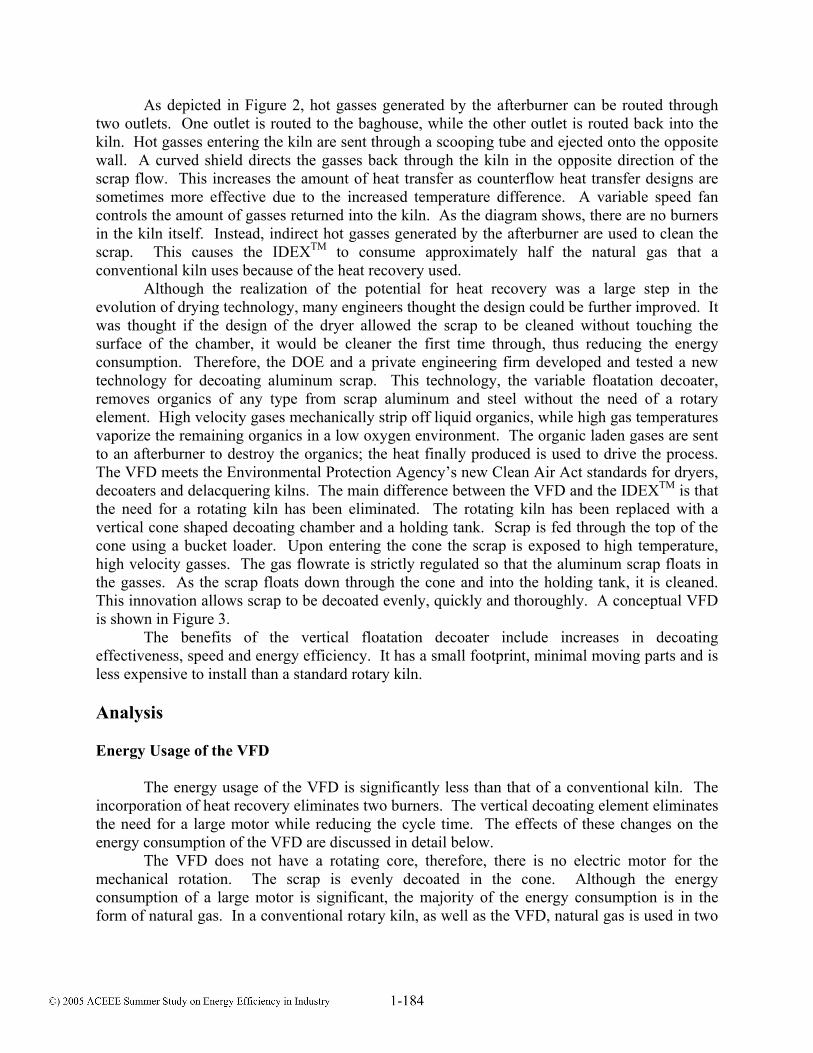
As depicted in Figure 2, hot gasses generated by the afterburner can be routed through two outlets. One outlet is routed to the baghouse, while the other outlet is routed back into the kiln. Hot gasses entering the kiln are sent through a scooping tube and ejected onto the opposite wall. A curved shield directs the gasses back through the kiln in the opposite direction of the scrap flow. This increases the amount of heat transfer as counterflow heat transfer designs are sometimes more effective due to the increased temperature difference. A variable speed fan controls the amount of gasses returned into the kiln. As the diagram shows, there are no burners in the kiln itself. Instead, indirect hot gasses generated by the afterburner are used to clean the scrap. This causes the IDEXTM to consume approximately half the natural gas that a conventional kiln uses because of the heat recovery used. Although the realization of the potential for heat recovery was a large step in the evolution of drying technology, many engineers thought the design could be further improved. It was thought if the design of the dryer allowed the scrap to be cleaned without touching the surface of the chamber, it would be cleaner the first time through, thus reducing the energy consumption. Therefore, the DOE and a private engineering firm developed and tested a new technology for decoating aluminum scrap. This technology, the variable floatation decoater, removes organics of any type from scrap aluminum and steel without the need of a rotary element. High velocity gases mechanically strip off liquid organics, while high gas temperatures vaporize the remaining organics in a low oxygen environment. The organic laden gases are sent to an afterburner to destroy the organics; the heat finally produced is used to drive the process. The VFD meets the Environmental Protection Agency’s new Clean Air Act standards for dryers, decoaters and delacquering kilns. The main difference between the VFD and the IDEXTM is that the need for a rotating kiln has been eliminated. The rotating kiln has been replaced with a vertical cone shaped decoating chamber and a holding tank. Scrap is fed through the top of the cone using a bucket loader. Upon entering the cone the scrap is exposed to high temperature, high velocity gasses. The gas flowrate is strictly regulated so that the aluminum scrap floats in the gasses. As the scrap floats down through the cone and into the holding tank, it is cleaned. This innovation allows scrap to be decoated evenly, quickly and thoroughly. A conceptual VFD is shown in Figure 3.
The benefits of the vertical floatation decoater include increases in decoating effectiveness, speed and energy efficiency. It has a small footprint, minimal moving parts and is less expensive to install than a standard rotary kiln. Analysis Energy Usage of the VFD The energy usage of the VFD is significantly less than that of a conventional kiln. The incorporation of heat recovery eliminates two burners. The vertical decoating element eliminates the need for a large motor while reducing the cycle time. The effects of these changes on the energy consumption of the VFD are discussed in detail below.
The VFD does not have a rotating core, therefore, there is no electric motor for the mechanical rotation. The scrap is evenly decoated in the cone. Although the energy consumption of a large motor is significant, the majority of the energy consumption is in the form of natural gas. In a conventional rotary kiln, as well as the VFD, natural gas is used in two
places: to accomplish decoating and to incinerate organics and oils from the aluminum. The main difference is a conventional rotary dryer uses direct heat to accomplish the drying, while the VFD uses waste gasses to drive the decoating process. The VFD is similar to the IDEXTM in this manner. Aside from the direct reduction in natural gas consumption, there are additional reductions due to indirect benefits of introducing hot metal directly into the furnace.
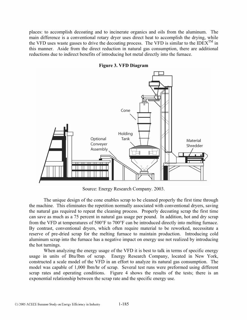
Figure 3. VFD Diagram
Source: Energy Research Company. 2003.
The unique design of the cone enables scrap to be cleaned properly the first time through the machine. This eliminates the repetition normally associated with conventional dryers, saving the natural gas required to repeat the cleaning process. Properly decoating scrap the first time can save as much as a 75 percent in natural gas usage per pound. In addition, hot and dry scrap from the VFD at temperatures of 500°F to 700°F can be introduced directly into melting furnace. By contrast, conventional dryers, which often require material to be reworked, necessitate a reserve of pre-dried scrap for the melting furnace to maintain production. Introducing cold aluminum scrap into the furnace has a negative impact on energy use not realized by introducing the hot turnings. When analyzing the energy usage of the VFD it is best to talk in terms of specific energy usage in units of Btu/lbm of scrap. Energy Research Company, located in New York, constructed a scale model of the VFD in an effort to analyze its natural gas consumption. The model was capable of 1,000 lbm/hr of scrap. Several test runs were preformed using different scrap rates and operating conditions. Figure 4 shows the results of the tests; there is an exponential relationship between the scrap rate and the specific energy use.

Figure 4. Test Data for the Vertical Flotation Decoater
Source: Industrial Technologies Program. 2000.
Productivity Improvements of the VFD The VFD offers productivity benefits in addition to reduced energy consumption, including reduced decoating time and increased throughput. While this is due to a number of design changes, the vertical cone is the only fundamental difference between the VFD and its older counterpart. Due to the vertical decoating chamber, the gasses within the cone move with higher velocities than a standard kiln. Measurements taken by Energy Research Company on the VFD model show that an increase of up to six times the flowrate is possible by using a vertical chamber. The specific flowrate of the gasses in the cone is designed to maintain a floating bed of scrap depending on the scrap feed rate. Therefore, increased velocity is required in order for the VFD to operate properly. This design innovation enables scrap to be decoated over a shorter time period as compared to conventional rotary kilns. The increase in the velocity of the gasses results in an increase of the heat transfer coefficient. Due to the increased heat transfer coefficient, the time required to decoat scrap can be reduced.
Figure 5 illustrates that as the gas velocity increases the heat transfer coefficient increases, thereby raising the overall energy efficiency of the VFD. Typical velocities in the VFD range from 40 ft/sec to 80 ft/sec. As the graph shows, the relationship between the gas velocity and the heat transfer coefficient in this range is linear. The increased heat transfer coefficient enables the VFD to decoat scrap quickly and efficiently as compared to a conventional kiln resulting in increased productivity and lower operating costs.
Figure 6 illustrates an exponential relationship between the gas velocity and the relative decoating time. The relative decoating time refers to percent time as compared to a conventional kiln. The graph shows that as the gas velocity is increased, the amount of time saved by using the VFD as opposed to a conventional system increases. However, the curve approaches 20 percent time asymptotically, denoting a limit on the time savings. Because the speeds at which gasses flow through the cone of the VFD are dependent on the scrap rate, the most efficient operation of the VFD would be at higher loads. At high scrap rates the specific energy usage is

small, the gas velocity is high and the scrap is decoated in less time. Therefore, a VFD replacement is most attractive in the scrap rate range of 6,000 lbm/hr and higher.
As described earlier, conventional kilns represent a bottleneck in the aluminum recycling process. The reduction in decoating time would enable facilities to eliminate the bottleneck associated with conventional kilns while increasing the amount of aluminum produced each day. In addition to the decreased cycle time of the VFD, scrap from the VFD is cleaned more thoroughly the first time through. Built up residue on the interior of a conventional kiln has a tendency to accumulate on the scrap as it is fed through the chamber. The higher velocity gasses in a VFD do not allow buildup on the interior walls or the scrap, enabling the scrap to be cleaned more thoroughly the first time through. Figure 7 shows decoated scrap after one pass through a conventional rotary kiln. As the picture shows, this scrap contains residual organics and cutting oils. It is likely that the decoating process would have to be repeated for this sample of scrap. Figure 8 shows the decoated scrap after one pass through a VFD. This scrap does not have any residual oils or organics and is significantly cleaner than the previous picture. The scrap in this picture can be directly fed into the melting furnace eliminating the bottleneck.
It is important to note that there is a small, but noticeable, increase in the size of the fan used by the VFD to accommodate the higher gas velocities. This small increase is insignificant when compared to the value of reduced decoating time. The improvement in the quality of the scrap, as well as the reduced cycle time, results in increased profit potential.
Figure 5. Heat Transfer Coefficient
Source: Energy Research Company. 2003.
Figure 6. Relative Decoating Time
Source: Energy Research Company. 2003.
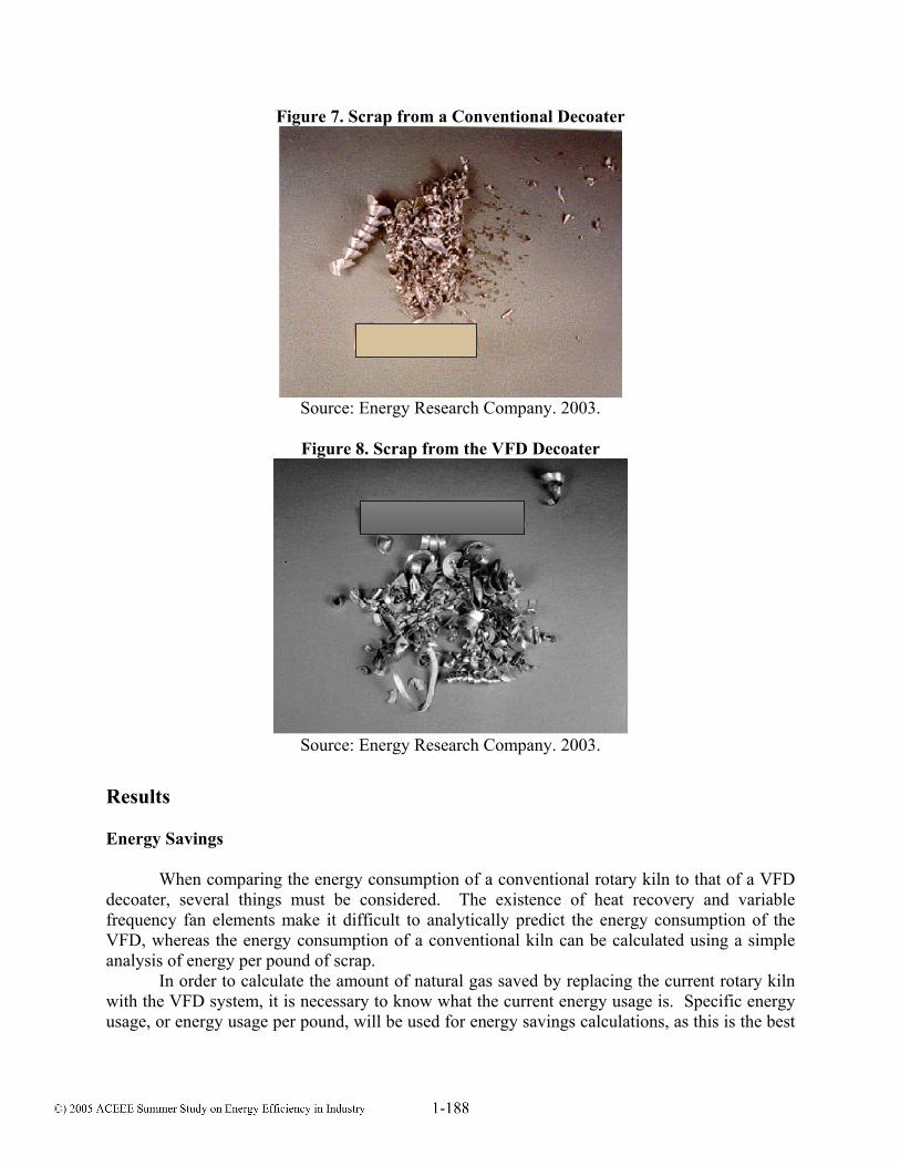
Figure 7. Scrap from a Conventional Decoater
Source: Energy Research Company. 2003.
Figure 8. Scrap from the VFD Decoater
Source: Energy Research Company. 2003.
Results Energy Savings
When comparing the energy consumption of a conventional rotary kiln to that of a VFD
decoater, several things must be considered. The existence of heat recovery and variable frequency fan elements make it difficult to analytically predict the energy consumption of the VFD, whereas the energy consumption of a conventional kiln can be calculated using a simple analysis of energy per pound of scrap. In order to calculate the amount of natural gas saved by replacing the current rotary kiln with the VFD system, it is necessary to know what the current energy usage is. Specific energy usage, or energy usage per pound, will be used for energy savings calculations, as this is the best

way to express each of the system’s effective energy usage. In addition, the specific energy usage of the VFD has already been measured and graphed in terms of specific energy usage. On average, the scrap rate through the kiln for the facility is 6,000 lbsm/hr. The annual operating hours were determined to be 6,336 hr/yr after consulting plant management. Natural gas metering data collected on site revealed that the natural gas usage of the dryer was 30% of the natural gas usage of the building, which equates to 74,000 MMBtu/yr. The specific energy use of the kiln, SEUC, can be found using the following equation:
SEUC= K
1 K
GU(C ×SR×h )
where GUK = annual natural gas usage of the kiln, 74,000 MMBtu/yr SR = average scrap rate kiln, 6,000 lbsm/hr hK = annual operating hours of the kiln, 6,336 hr/yr C1 = conversion constant, 1×10⁻⁶ MMBtu/Btu The specific energy use of the kiln, SEUC, is then:
SEUC= -674,000
(1×10 ×6,000×6,336)
SEUC=1,950 Btu/lbm According to Figure 4, at a scrap feed rate of 6,000 lbsm/hr the specific energy usage of the VFD would be 1,000 Btu/lbsm. Comparing this specific energy usage to the specific energy usage of the current system, this facility would realize a savings of 950 Btu/lbsm. The total annual natural gas savings, GS, and the total annual natural gas cost savings, GCS, can be calculated using the following equations: GS= C P K 1(SEU -SEU )×SR×h ×C and GCS=GS×GC where SEUP = specific energy usage of the VFD, 1,000 Btu/lbm The total annual natural gas savings, GS, and the total annual natural gas cost savings, GCS, are then: GS= -6(1,950-1,000)×6,000×6,336×1×10 GS=36,000 MMBtu/yr GCS=36,000 MMBtu/yr×$4.43/MMBtu/yr GCS=$160,000/yr These calculations show a reduction of 50% in the natural gas usage of the drying process. This represents a considerable impact on the process’ energy consumption. Using this facility as a benchmark, a 50% reduction in the natural gas used for drying by facilities in the United States represents potential for a significant decrease in not only energy consumption, but also in associated volatile emissions. It should be noted that both the VFD and the conventional

rotary kiln energy consumption are both once through systems. Since, in many cases, the conventional system requires the metal to pass through up to four times before the quality of scrap is achieved, the energy consumption per pound of scrap for the conventional system is higher. Productivity Savings In addition to the energy savings resulting from the VFD’s installation, this facility would also realize a reduction in cycle time. The success of the VFD to reduce the time required to decoat is based on its high heat transfer coefficient, which increases the rate and effectiveness of decoating. With the type of scrap and feed rate at this facility, the velocity would be 60 ft/sec, according to the VFD’s designer. As a result of the vertical decoating chamber, the VFD at this facility should be capable of decoating the same amount of scrap in 80% less time than a conventional decoater, based on the graph shown in Figure 6. The details of the impact of such a time decrease are beyond the scope of this report. However, by analyzing the amount of time spent drying scrap, 6,336 hr/yr, at a scrap rate of 6,000 lbsm/hr, it is estimated that this facility decoats a total of 38 million pounds of scrap per year. By installing the VFD, this facility would be able to produce 38 millions pounds of scrap in 1,267 hours, corresponding to an 80% reduction in cycle time. Conversely, the facility could produce 152 million more pounds of scrap per year at 6,336 hr/yr. This dramatic output increase would enable the facility to increase its production and its profit potential. Furthermore, if the facility is not capable of producing this level of output for any reason, the VFD would be operating less time throughout the year, which would result in further cost savings due to less operating time. Conclusion Over the past several years the aluminum industry has been actively pursuing energy conservation improvements. In 2002 alone, the industry reduced its energy consumption by 22 percent. [AA2] The VFD is a primary example of the effort put forth by the aluminum industry to formulate and implement new energy related innovations. The VFD is a solution to many of the drawbacks of a conventional kiln. Its rapid decoating time, and ability to produce clean product the first time through, would enable facilities to eliminate their bottlenecks as well as increase their output and profit margin. Its small footprint makes installation easy and affordable. The VFD has no moving parts, which reduces the need for maintenance and cleaning. It has the capability of reducing the natural gas usage by half, which would result in lower operating costs and decreased VOC emissions. These improvements to the VFD make it an ideal replacement for the conventional rotary kiln. At the plant studied, the VFD has the potential to reduce annual natural gas consumption of the drying process by 36,000 MMBtu, a decrease of 50%. Additionally, VOC emissions by the plant would be reduced and the amount of energy used to melt the scrap decreased. With its improved design, the VFD has the potential to save over 17 trillion Btus of natural gas in the U.S. alone. [EERE] The increasing volatility of the natural gas market along with the increasing demand for aluminum makes energy and productivity related advances crucial considerations for the industry. The capability of the VFD to reduce operating costs, decrease cycle time, and increase profit margins will make the VFD a viable option for scrap decoaters in the United States and worldwide.
References [AA1] The Aluminum Association, Inc. 2004. “Environment and Climate Change: Conservation,
Preservation, and Recycling.” Available online: www.aluminum.org/Content/ NavigationMenu/The_Industry/Government_Policy/Climate_Change/ Climate_Change.htm. Washington, D.C.
[AA2] The Aluminum Association, Inc. 2004. “In-Depth Information/Recycling Process.”
Available online: www.aluminum.org/Content/NavigationMenu/ The_Industry/Recycling/In-depth_information/In-depth_information.htm. Washington, D.C.
[CD] China Daily Website. 2005. “GDP Surge Epitomizes Sound Growth Of Economy.”
Available online: www.chinadaily.com.cn/en/doc/2004-01/21/content_300663.htm. [CIIC] China Internet Information Center. 2005. “Chinese and Foreign Institutions Predict
China's 2000-10 Economic Growth.” Available online: www.china.org.cn/baodao/ english/newsandreport/2002june1/11-5.htm.
[CS] Credit Suisse Asset Management. 2005. Asset Management Market Update, January 2005.
Available online: lu.csam.com/dss/fundsamdi2/mu_0501b_eng.pdf. [EERE] Energy Efficiency and Renewable Energy. 2005. “Innovative Vertical Floatation Melter
(VFM) and Scrap Dryer.” Aluminum Project Fact Sheet. Available online: www.eere.energy.gov/industry/metalcasting/pdfs/floatation.pdf. Washington, D.C.
[ERCO] Energy Resource Company. 2005. “VFM Decoater.” Available online: www.er-
co.com/rd_decoat.htm. New York, N.Y. [ITP] Industrial Technologies Program. 2000. “Indirect-Fired Kiln Conserves Scrap Aluminum
and Cuts Costs.” Energy Matters. Energy Matters Newsletter. November/December 2000. Available online: www.oit.doe.gov/bestpractices/energymatters/ nov2000sup_kiln.shtml. Washington, D.C.
[NRC] National Resource Center. 2005. Available online: http://www.nrcan.gc.ca/
mms/pdf/nfo/nfo00/alum-e.pdf. Ottawa, ON, Canada.