dávila pinto martín alejandro gallo alvarez francis
TRANSCRIPT

UNIVERSIDAD SAN FRANCISCO DE QUITO USFQ
Colegio de Ciencias e Ingenierías
Design of a Beer Bottle Washer Machine .
Dávila Pinto Martín Alejandro Gallo Alvarez Francis Gabriel Nolivos López Iván Estefano Villacís Navas Andi Gabriel
Ingeniería Mecánica
Trabajo de integración curricular presentado como requisito para la obtención del título de
INGENIEROS MECÁNICOS
Quito, 14 de mayo de 2020

2
UNIVERSIDAD SAN FRANCISCO DE QUITO USFQ
COLEGIO DE CIENCIAS E INGENIERIAS
HOJA DE CALIFICACIÓN DE TRABAJO DE INTEGRACIÓN CURRICULAR
Design of a Beer Bottle Washer Machine
Dávila Pinto Martín Alejandro
Gallo Alvarez Francis Gabriel
Nolivos López Iván Estefano
Villacís Navas Andi Gabriel
Calificación: / Nombre del profesor, Título académico Juan Sebastián Proaño, PhD.
Firma del profesor: _____________________________
Quito, 14 de mayo de 2020

3
Derechos de Autor
Por medio del presente documento certifico que he leído todas las Políticas y Manuales
de la Universidad San Francisco de Quito USFQ, incluyendo la Política de Propiedad
Intelectual USFQ, y estoy de acuerdo con su contenido, por lo que los derechos de propiedad
intelectual del presente trabajo quedan sujetos a lo dispuesto en esas Políticas.
Asimismo, autorizo a la USFQ para que realice la digitalización y publicación de este
trabajo en el repositorio virtual, de conformidad a lo dispuesto en el Art. 144 de la Ley Orgánica
de Educación Superior.
Firma de los estudiantes: _______________________________________
_______________________________________
_______________________________________
_______________________________________
Nombres y apellidos: Martín Alejandro Dávila Pinto
Francis Gabriel Gallo Alvarez Iván Estefano Nolivos López Andi Gabriel Villacis Navas Código: 00131159 00114116 00132504 00118165 Cédula de identidad: 1726444282 1719564054 1718832197 0502931793 Lugar y fecha: Quito, 14 de mayo de 2020

4
ACLARACIÓN PARA PUBLICACIÓN
Nota: El presente trabajo, en su totalidad o cualquiera de sus partes, no debe ser considerado
como una publicación, incluso a pesar de estar disponible sin restricciones a través de un
repositorio institucional. Esta declaración se alinea con las prácticas y recomendaciones
presentadas por el Committee on Publication Ethics COPE descritas por Barbour et al. (2017)
Discussion document on best practice for issues around theses publishing, disponible en
http://bit.ly/COPETheses.
UNPUBLISHED DOCUMENT
Note: The following capstone project is available through Universidad San Francisco de Quito
USFQ institutional repository. Nonetheless, this project – in whole or in part – should not be
considered a publication. This statement follows the recommendations presented by the
Committee on Publication Ethics COPE described by Barbour et al. (2017) Discussion
document on best practice for issues around theses publishing available on
http://bit.ly/COPETheses.

5
RESUMEN
En este documento, el diseño de una lavadora de botellas de cerveza se lleva a cabo considerando los requerimientos del cliente. Los criterios de ingeniería se aplican para una selección final del prototipo y selección de material de los componentes. Se consideran las restricciones de diseño, especialmente a partir del presupuesto y ciertos componentes. Una vez que se elige un diseño final, se elabora un proceso de fabricación completo. Durante su proceso de diseño, se considera que las normas de ingeniería y operativas mantengan la seguridad del operador durante el proceso de lavado. Los cálculos y simulación de software: Sistema de tuberías, transferencia de calor y diseño estructural del rack se realizan para validar el diseño seleccionado. Los resultados de la simulación validan los datos del sistema de calefacción y los cálculos estructurales del rack, pero el sistema de tuberías debe rediseñarse dado que la bomba está sobredimensionada. Se elabora un manual de fabricación y operación considerando los resultados de la simulación. Se elabora un plan de prueba y validación de experimento para ejecutar en la máquina cuando su ensamble final esté listo. Los diseñadores han propuesto un indicador de éxito que la máquina debe seguir para garantizar parámetros de operación adecuados. Los diseñadores sugieren los parámetros de operación de seguridad; estas instrucciones deben seguirse durante el diseño y la operación. Una vez finalizado el diseño, el trabajo futuro propone la elaboración completa del prototipo siguiendo los planos de taller y todos los estándares. La propuesta de presupuesto incluye considerar la mejor opción de materiales y fabricantes. Al final, el diseño cumple con todos los requisitos del cliente y todos los estándares de ingeniería considerados por los diseñadores, las mejoras podrían llevarse a cabo en el diseño mediante la optimización de algunos diseños y materiales.
Palabras Clave: Sistema de tuberías, simulación, subsistemas, estándares de
ingeniería, plan de prueba de prototipo, sistema de calentamiento, automatización, cotización, diseño asistido por computadora
6
ABSTRACT
At this document, the design of a beer bottle washing machine is carried out by considering the requirements of the client. Engineering criteria is applied for a final prototype selection and component material selection. Design constraints are considered, specially from budget and certain components. Once a final design is chosen, a complete manufacturing process is elaborated. During its design process, engineering and operative standards are considered to keep operator security during the washing process. Calculations and software simulation of: Piping system, heat transfer and structural design of the rack are done to validate the selected design. Simulation Results validates the data of heating system and structural calculations of rack, but the piping system must be redesigned given that the pump is oversized. A Manufacture and operation manual is elaborated considering the simulation results. An experiment validation and test plan are elaborated to execute on the machine when its final assembly is ready. Designers have proposed a success indicator that the machine has to follow to guarantee adequate operation parameters. Safety operation parameters are suggested by the designers, these instructions must be followed during design and operation. Once the design finished, future work proposes the complete elaboration of the prototype by following the executed workshop planes and all the standards. Budget proposal is including, considering the best option of materials and manufacturers. At the end, the design accomplishes with all the client requirements and all the engineering standards considered by the designers, improves could be carried out into the design by optimizing some designs and materials.
Keywords: Piping System, simulation, subsystems, engineering standards, prototype
test plan, heating system, automation, manufacturing, quotation, computer aided design

7
TABLA DE CONTENIDO
ACLARACIÓN PARA PUBLICACIÓN ........................................................................... 4
UNPUBLISHED DOCUMENT .......................................................................................... 4
RESUMEN .......................................................................................................................... 5
ABSTRACT......................................................................................................................... 6
LIST OF FIGURES .......................................................................................................... 12
LIST OF TABLES ............................................................................................................ 19
INTRODUCTION ............................................................................................................... 7
PROBLEM STATEMENT AND PROJECT SPECIFICATION .......................................................... 8
DESIGN CONCEPTS AND SELECTIONS ................................................................................ 12
Water Heating ............................................................................................................. 13
Bottle-holder Rack ....................................................................................................... 13
Piping System .............................................................................................................. 14
EVALUATION AND SELECTION CONCEPTS ......................................................................... 14
Water heating .............................................................................................................. 15
Beer Bottle Rack .......................................................................................................... 15
Pipe Selection .............................................................................................................. 16
PROJECT MANAGEMENT ................................................................................................... 18
Activities Management ................................................................................................ 18
Budget Management .................................................................................................... 20
ENGINEERING STANDARDS ............................................................................................... 20
Stainless Steel managing ............................................................................................. 20
NaOH safety data sheet: Handling and hazards .......................................................... 23
8
Stainless Steel Welding ................................................................................................ 27
MATERIALS AND METHODS ...................................................................................... 28
MATERIAL AND COMPONENT SELECTION .......................................................................... 28
DESIGN FOR MANUFACTURING ............................................................................... 29
PIPING SYSTEM ................................................................................................................ 30
WATER HEATING SUBSYSTEM .......................................................................................... 31
BOTTLE-HOLDER RACK ................................................................................................... 32
WATER COMPARTMENTS .................................................................................................. 33
PLANIFICATION FOR EXECUTION ....................................................................................... 35
QUOTATION ..................................................................................................................... 37
Piping System Costs .................................................................................................... 37
Controller, Water Heating System and Basket costs ..................................................... 38
PROCESS DETAIL .............................................................................................................. 43
RESULTS AND DISCUSSION ........................................................................................ 45
DESIGN REPORT ............................................................................................................... 45
Pipelines ..................................................................................................................... 45
ENGINEERING EXPERIMENT FOR VERIFICATION ................................................................. 54
Leak Testing ................................................................................................................ 54
Pressure Testing .......................................................................................................... 54
Prototype Test Plan ..................................................................................................... 55
Pipe and bottle-holder rack dimensions test ................................................................. 56
Bottle-holder rack stress test ....................................................................................... 57
Flow rate and pressure test ......................................................................................... 57
Fluids temperature test ................................................................................................ 59

9
Time of operation test .................................................................................................. 59
SAFETY THROUGH DESIGN ............................................................................................... 62
RESULTS, DISCUSSION AND CONCLUSIONS ........................................................................ 67
Pipe simulation results analysis: ................................................................................. 67
Caustic soda piping system simulation results: ............................................................ 74
Bottle-holder rack structural simulation results analysis: ............................................ 76
FUTURE WORK................................................................................................................. 79
REFERENCES .................................................................................................................... 82
APPENDIXES ................................................................................................................... 84
APPENDIX A .................................................................................................................... 84
Engineering Drawings: ............................................................................................... 84
APPENDIX B – PROJECT MANAGEMENT ............................................................................ 97
Quotation Report: ....................................................................................................... 97
Gaant Chart: ............................................................................................................. 100
Piping System ............................................................................................................ 101
Reservoir System ....................................................................................................... 103
Pump ......................................................................................................................... 104
Water Heating System ............................................................................................... 105
Pump Controller ........................................................................................................ 106
Manufacturing Diagram ............................................................................................ 108
Leak Testing .............................................................................................................. 109
Pressure Testing ........................................................................................................ 113
Troubleshooting ........................................................................................................ 117
DESIGN, CONCEPTS AND SELECTIONS ............................................................................. 121
Water heating ............................................................................................................ 121

10
Beer Bottle Rack ........................................................................................................ 123
Pipe Selection ............................................................................................................ 125
ENGINEERING ANALYSIS ................................................................................................ 126
Milestone #1: Bottle-holder rack design .................................................................... 126
Milestone #2: Water Heating ..................................................................................... 135
Milestone #3: Automation .......................................................................................... 162
Milestone #4: Pressure drops and losses inside the pipe. ........................................... 164
MAINTENANCE AND OPERATION MANUAL ...................................................................... 179
Data sheet ................................................................................................................. 179
Part Description ........................................................................................................ 181
Preheating Process.................................................................................................... 188
Pump and flow rate setting ........................................................................................ 193
Troubleshooting ........................................................................................................ 194
Alignment problem .................................................................................................... 195
Clamping problems ................................................................................................... 196
Leaking problems ...................................................................................................... 196
Corrosion problems ................................................................................................... 197
Pump problems.......................................................................................................... 197
Heating failure .......................................................................................................... 197
Electric problems ...................................................................................................... 198
Troubleshooting Solutions ......................................................................................... 199
Maintenance of the piping system and identification of leaks ..................................... 199
Structural management.............................................................................................. 199
Heating System Maintenance ..................................................................................... 201
Safety operation ........................................................................................................ 204

11
MEETING MINUTES ........................................................................................................ 205

12
List of Figures
Figure # 1: Diagram of bottle washing process................................................................... 10
Figure # 2: Stainless Steel Tank .......................................................................................... 12
Figure # 3: Final design of the Rack ................................................................................... 17
Figure # 5: Final design of piping and tubing system .......................................................... 17
Figure # 4: Final design of water heating system. Reprinted from Alibaba 2020.
https://www.alibaba.com/product-detail/High-Resistance-Electrical-Coil-Stainless-
Steel_62340201772.html?spm=a2700.galleryofferlist.0.0.11c4e4ab2WkUMH .................... 17
Figure # 6: PVC Prototype designed by the Client .............................................................. 30
Figure # 7: Piping System Optimization .............................................................................. 31
Figure # 8: Electric Resistances illustration. Reprinted from Alibaba, 2020,
https://www.alibaba.com/product-detail/Solar-Water-Heater-Immersion-
Coil_62007207589.html ...................................................................................................... 32
Figure # 9: Basket optimization .......................................................................................... 33
Figure # 10: Tank Optimization ......................................................................................... 34
Figure # 11: External pipes ................................................................................................ 46
Figure # 12: Internal pipes .................................................................................................. 47
Figure # 13: Ferrule model standard ................................................................................... 47
Figure # 14: Ferrule design standard................................................................................... 48
Figure # 15: Water distributor model .................................................................................. 48
Figure # 16: Changes made to the Tank .............................................................................. 49

13
Figure # 17: Tank Design ................................................................................................... 50
Figure # 18: Dimensions of the bottle ................................................................................. 51
Figure # 19: Basket model .................................................................................................. 51
Figure # 20: Pump ½ HP .................................................................................................... 52
Figure # 21: Pump 1 HP ..................................................................................................... 52
Figure # 22: Valve model ................................................................................................... 53
Figure # 23: Washer Bottle Final Model ............................................................................. 53
Figure # 24: Height to measure .......................................................................................... 54
Figure # 25: Color scale of value of risks ........................................................................... 63
Figure # 26: Piping circuit for simulation in Pipeflow. ....................................................... 68
Figure # 27: System curve overload with the 1HP pump performance curve and operation
point of the system. .............................................................................................................. 69
Figure # 28: System results with the 1HP pump. ................................................................. 70
Figure # 29: Re-selected pump specifications. .................................................................... 72
Figure # 30: System curve overload with the re-selected pump performance curve and
operation point of the system for the water piping. .............................................................. 73
Figure # 31: System curve overload with the re-selected pump performance curve and
operation point of the system for the caustic soda piping. .................................................... 75
Figure # 32: load distribution at the bottle-holder rack during operation. ............................ 76
Figure # 33: Load magnitude applied to the bottle-holder rack during operation. ................ 77
Figure # 34: Von Mises stress at bottle-holder rack during operation .................................. 78

14
Figure # 35: Deformation at bottle-holder rack during operation. ....................................... 79
Figure # 36: Bottle holder basket ...................................................................................... 126
Figure # 37: Final Assembly ............................................................................................ 127
Figure # 38: Simplified structural system ......................................................................... 128
Figure # 39: Simplified structural system’s free body diagram ......................................... 128
Figure # 40: Equivalent system for a beam fixed at both ends........................................... 129
Figure # 41: Decomposition into sub-systems for the analyzed beam ............................... 130
Figure # 43: Water body drawn for simulation Analysis ................................................... 139
Figure # 44: Heating Element Drawn for Simulation Analysis .......................................... 140
Figure # 45: Stainless Steel Properties used during Simulation ......................................... 140
Figure # 46: Water Properties used during Simulation ...................................................... 141
Figure # 47: Water Tank (Top View) was supposed to be at Room Temperature .............. 141
Figure # 48: Water Tank (Isometric View) was supposed to be at Room Temperature ..... 142
Figure # 49: Water was supposed to be at an average Temperature of 16.5 C ................... 142
Figure # 50: The Heating Element was supposed to give 12 kW to the System ................. 143
Figure # 39: Mesh generated by the Software ................................................................... 143
Figure # 40: Results got from Simulation ......................................................................... 144
Figure # 53: Results got after using convection of water ................................................... 145
Figure # 42: Error caused due to the consideration of Single Phase Simulation. ................ 147
Figure # 43: Watertight Geometry created from the CAD files ......................................... 148

15
Figure # 56: Stainless Steel Properties used during Simulation of the Water Distributor System
......................................................................................................................................... 149
Figure # 45: Statistics of the Watertight Mesh .................................................................. 151
Figure # 46: Final Mesh Obtained .................................................................................... 152
Figure # 59: Residuals after 1100 Iterations...................................................................... 153
Figure # 48: Average Temperature at the Outlet ............................................................... 153
Figure # 49: Path lines of Static Temperature through the Piping System ......................... 154
Figure # 50: Contours of Static Temperature through the Water Distributor System ......... 155
Figure # 51: Pathlines of Static Temperature through the Water Distributor System ......... 156
Figure # 52: Average Temperature at the Outlet ............................................................... 157
Figure # 53: Average Flow Rate at the nozzle .................................................................. 158
Figure # 66: Contours of Static Velocity through the Piping System................................. 159
Figure # 55: Velocity Vectors through the Piping System ................................................. 160
Figure # 56: Contours of Static Velocity through the Water Distributor System ............... 160
Figure # 57: Velocity Vectors through the Water Distributor System ............................... 161
Figure # 58: Velocity Contours at the Nozzle ................................................................... 162
Figure # 71: Conditioning circuit model. Reprinted form Electronic Instrumentation. Miguel
A. Perez and others, Ed. Thomson-Paraninfo.................................................................... 163
Figure # 72: First subsystem considered to solve the problem........................................... 165
Figure # 74: Valve constant for minor losses. Reprinted from Thermal Energy Systems, S.
Penoncello, ....................................................................................................................... 166

16
Figure # 61: Constant for the entrance of the pipe. Reprinted from Thermal Energy Systems,
S. Penoncello, 2014. .......................................................................................................... 166
Figure # 75: Moody Chart. Reprinted from: Fundamental of Fluid Mechanics. Munson, B.,
Young, D., & Okiishi, 2017............................................................................................... 168
Figure # 76: Roughness defined for different materials. Reprinted from Thermal Energy
Systems, S. Penoncello, 2014. ............................................................................................ 168
Figure # 77: Illustration of subsystem 2. ........................................................................... 169
Figure # 78: Elbow friction data. Reprinted from Thermal Energy Systems, S. Penoncello,
2014 .................................................................................................................................. 172
Figure # 67: Illustration of subsystem 3 ............................................................................ 173
Figure # 80: Pipe exit K constant value Reprinted from Thermal Energy Systems, S.
Penoncello, 2014. .............................................................................................................. 175
Figure # 69: T’s loss constant considered for minor losses. Reprinted from: Fundamental of
Fluid Mechanics. Munson, B., Young, D., & Okiishi, 2017. .............................................. 175
Figure # 82: Plot result of the piping system ..................................................................... 178
Figure # 83: List of parts of Bottle Washer Machine ........................................................ 184
Figure # 84: Steps 1 and 2 ................................................................................................ 186
Figure # 85: Colocation of Nozzles .................................................................................. 187
Figure # 86: Step 4 ........................................................................................................... 187
Figure # 87: Steps 5, 6, 7 .................................................................................................. 188

17
Figure # 78: Pyrometer and Panel Control. Reprinted from Alibaba, 2020,
https://www.alibaba.com/product-detail/Solar-Water-Heater-Immersion-
Coil_62007207589.html .................................................................................................... 189
Figure # 79: Water Mark .................................................................................................. 189
Figure # 80: Water tank .................................................................................................... 190
Figure # 81: Start Button . Reprinted from Alibaba, 2020, https://www.alibaba.com/product-
detail/Custom-high-accuracy-indoor-control-
panel_62408482217.html?spm=a2700.galleryofferlist.0.0.70931d03sa0Hnn&s=p ............ 191
Figure # 82: Timer. Reprinted from Alibaba, 2020, https://www.alibaba.com/product-
detail/Custom-high-accuracy-indoor-control-
panel_62408482217.html?spm=a2700.galleryofferlist.0.0.70931d03sa0Hnn&s=p ............ 192
Figure # 83: Pump controller System. Reprinted from Alibaba, 2020,
https://www.alibaba.com/product-detail/Development-board-Arduinos-UNO-R3-
atmega328p_60838481820.html?spm=a2700.galleryofferlist.0.0.2dfd7d0ff8PjA9&s=p.... 193
Figure # 84: Control Panel Box. Reprinted from Alibaba 2020,
https://www.alibaba.com/trade/search?fsb=y&IndexArea=product_en&CatId=&SearchText=
control+panel .................................................................................................................... 201
Figure # 85: Stainless Steel Cleaner. . Reprinted from Alibaba 2020,
https://www.alibaba.com/product-detail/stainless-steel-cleaner-polish-spray-
water_62545455142.html?spm=a2700.galleryofferlist.0.0.72175621brbcJx&s=p ............. 202
Figure # 86: Stainless Steel Resistance. Reprinted from Alibaba 2020,
https://www.alibaba.com/product-detail/electrical-resistance-tubular-for-water-
heater_60023836658.html?spm=a2700.galleryofferlist.0.0.5925e4abxDOJI2&s=p ........... 203

18
Figure # 87: PPE Needed. Reprinted from Alibaba 2020, https://www.alibaba.com/product-
detail/electrical-resistance-tubular-for-water-
heater_60023836658.html?spm=a2700.galleryofferlist.0.0.5925e4abxDOJI2&s=p ........... 203
Figure # 88: first meeting minute ...................................................................................... 205
Figure # 89: second meeting minute ................................................................................. 205
19
List of Tables
Table # 1: Weighted Objectives .................................................................................. 12
Table # 7: Schedule of activities ................................................................................. 18
Table # 8: European Standards .................................................................................. 23
Table # 9: Handling and storage precautions for NaOH ............................................. 24
Table # 10: Hazard information for NaOH ................................................................. 26
Table # 11: Criteria selection for Stainless Steel ......................................................... 29
Table # 12: Detailed dates ........................................................................................... 35
Table # 13: Piping system detail cost .......................................................................... 37
Table # 14: Detail Costs of basket, water heater and pump controller .......................... 38
Table # 15: Success Indicator ..................................................................................... 41
Table # 16: System success indicator .......................................................................... 42
Table # 17: Detailed Process for Manufacturing ........................................................ 43
Table # 21: Engineering criteria and test plan requirements ........................................ 55
Table # 22: Specific parameters vs test plan to validate them ...................................... 60
Table # 23: Value of risk quantified by the relation probability - impact of risks ......... 63
Table # 24: Color scale of value of risks ..................................................................... 66
Table # 28: Gaant Chart for manufacturing process ................................................... 100
Table # 29: Piping system part list ............................................................................ 101
Table # 30: Reservoir system part list ....................................................................... 103
Table # 31: Pump Part List ....................................................................................... 104

20
Table # 32: Composed by two parts that contains all the parameters to be measure and
controlled by the manufacturers ................................................................................ 105
Table # 33: Pump Controller part list ........................................................................ 106
Table # 34: Leak Test Parameters ............................................................................. 109
Table # 35: Pressure Testing Parameters................................................................... 113
Table # 36: Troubleshooting Solutions ..................................................................... 117
Table # 2: Selection Criterion for water heating ....................................................... 121
Table # 3: Criteria applied for the selection of beer bottle rack ................................ 123
Table # 4: Conclusion of the selection of the Rack .................................................... 123
Table # 5: Criteria applied for the selection of the piping system .............................. 125
Table # 6: Conclusion of the piping system selection ................................................ 125
Table # 18: Data obtained from the system ............................................................... 164
Table # 19: Iterations table obtained with the equations system................................. 176
Table # 20: Head result of the system solved for different flow rates. ........................ 177
Table # 25: Data Sheet of the Beer Bottle Washer Machine ...................................... 179
Table # 26: List of Parts ........................................................................................... 182

7
INTRODUCTION
A Beer Bottle Washer Machine was designed for the Food Engineering Plant at
Universidad San Francisco de Quito, where students produce and bottle sodas, seer and
other beverages. Moreover, to reduce their footprint, they reuse their beer bottles, and
wash them by hand. However, they needed a device to help them to do it in a fastest,
easiest and more efficient way.
The main requirements of the Beer Bottle Washer Machine were specifically
made by the client, who asked for the device to have a production rate of 290 Beer Bottles
and 2 Beer Barrel Containers per hour (80 Beer Bottles & 2 Beer Barrel Containers
a day). The device had to perform 3 Washing Cycles (Bottle Pre-Washing, Washing &
Residues Removal and Rinse) that last 3 minutes each. Moreover, the Beer Bottle
Washer Machine had to be manufactured using Stainless Steel, use Sodium Hydroxide
(NaOH) during the Washing Cycle and Recirculate Heated Water (80 Celsius Degrees)
during the Rising Cycle.
The Design of the Beer Bottle Washer Machine had to be approached around
three constrains. The First one supposed the use of some equipment -i.e. a Squared
Shape (62 x 82 x 50 cm) Stainless Steel Tank and 2 Centrifugal Pumps (1 HP and 0.5
HP). The Second Constrain referred to the fact that all the parts of the device had to be
easily dismountable for being washed without much effort. The Third Constrain required
that the Beer Bottle Washer Machine costs at most 300 USD because that was the Budget
assigned for the Project.

8
8
Considering all the requirements described before, a Prototype of the Beer Bottle
Washer Machine was Designed and it is shown in Figure # 23. It uses the Stainless-Steel
Tank provided and it is divided into two compartments. In this way, the Beer Bottle
Washer Machine is able to use two fluids -i.e. Sodium Hydroxide (NaOH) and Heated
Water- during its operation. Both fluids are moved by the 2 Centrifugal Pumps provided
and go through a dismountable stainless-steel piping system to get into the Beer Bottles.
The Distributing System feeds 24 Beer Bottles per cycle in order to reach a production
rate required. This is possible by placing the Beer Bottles into a Bottle holder rack which
ease the transportation of the bottles around the device.
However, the Third Constrain was not met because the Bottle Washer Machine
was quoted in 1942.68 USD. But it is almost impossible to get the device built for 300
USD because it is made of Stainless Steel, which is a really expensive material to work
with. The future steps are the manufacturing and testing of the device, since Food
Engineering Plant Managers already approved the design shown in Figure # 23. For this
reason, it can be said that the scope of the project was reached.
Problem Statement and Project Specification
The present project represents the Design of a Small-Scale Bottle Washer
Machine for the Universidad San Francisco de Quito (USFQ) Food Engineering Plant.
The plant is dedicated, among other activities, to the production of Craft Beer reusing
their Beer Bottles. In this way, they have to wash 80 Beer Bottles by hand every day. This
procedure takes a big inversion of time. Also, by doing a manual washing the norms and
regulations given for this process can't be met since it involves very high temperatures
and dangerous chemical compounds.

9
9
Within the alimentary industry there are a lot of bottle washer machines but most
of them are dedicated to the large and medium scale industries. It is not common to find
machines for the small industry they usually are design for capacity of thousands to
millions of bottles per hour. The USFQ uses its food Plant mostly for academic purposes
this is the why a small machine that meet their requirements is very necessary where a
production don’t exceed the 100 bottles per day and this activity is done just a couple
days a week. A small washer machine with a washer capacity of tens to a couple of
hundreds, top, is very necessary for this kind of industries where the production scale is
very low compared to the other industries.
The process involves two different treatment zones simplified from the big washer
machines designs. The caustic zone is the first part of the process where the chemical
compound NaOH (sodium hydroxide) also known as caustic soda, is pumped inside each
bottle at 30-35 ºC resulting in the elimination of microbes and dirt residues. In the hydra
zone, water is pumped to the bottles at 75-85ºC, this temperature ensures that the water
can reach the smallest cracks in the glass removing all the caustic soda remaining from
the previous process. (Gajjar, Patel & Singh, 2015) These temperatures are very important
to the process to ensure the cleaning is doing correctly. Another parameter which must
be considered for a well performed process cycle time (time the bottles spend in each
zone), “Certain amount of time is required to heat up the bottles and cool down for the
beverage filling operations. Time considered is the time required for the caustic soda to
penetrate the bottle, spray inside the bottle to remove the dirt and mud, bottles and bottle
carriers drain off the washing compound before the next treatment zone and completely
drain the rinse water before discharging from the bottle washer machine.” (Gajjar, Patel
& Singh, 2015)

10
10
Figure # 1: Diagram of bottle washing process
The group general objective for the project is to build an automatic small-scaled
bottle washer that fulfill the requirements for machines used in the Ecuadorian food
industries which will be discussed further ahead in the report. The requirements made for
this project will be listed below:
The Universidad San Francisco de Quito Food’s Engineering Plant provided a
stainless-steel tub which should be used for the entire process, so it was divided into 2
Compartments. They also provided 2 Centrifugal Pumps to move the Washing Fluids that
will take part in the process.
1. The process will take two treatment zones: the caustic zone and the hydra zona.
2. The whole process must be automatic; this includes the pump and the heating
system.
3. The prototype should be capable of being completely disarmed for an easier
cleaning.
Infeed Pre-Heating Caustic Hydra Rinsing Discharge

11
11
4. The system should be capable to wash at least 80 beer bottles of two different
sizes: 12 oz. And 22 oz. And 2 beer barrels.
5. The heating system must be capable of heating water at 75-85 ºC (hydra zone)
and caustic soda at 30-35 ºC (caustic zone)
6. For a better assembly of the system, a bottle holder basket should be design along
the pipe and automatization needed in the project.
7. All the machine should be built with the appropriate norms and requirements of
the Ecuadorian alimentary industry.
The machine should have a piping system to pump different liquid compounds
into each zone. The piping system should begin extracting the compound from its
reservoir located in each half of the tub.
The project considers five different parameters for the development of the
weighted objectives which are: cost, size, precision, weight and operating safety. Being
a budget-limited project, the cost of the system is the most critical parameter overall.
Followed by size and precision, these parameters are almost as important as the
first one since the prototype to develop must be the smallest and as accurate as possible
due to the small dimension tolerance of the system itself. The weight and operation
systems are both equal important for the project design. The weighted objective table
shown below has been made with these parameters.

12
12
Table # 1: Weighted Objectives
CRITERIA Cost Size Precision Weight Operating
Safety
E+1 Weighted
Cost - 1 1 1 1 4 0,4
Size 0 - 1 1 1 3 0,3
Precision 0 0 - 1 1 2 0,2
Weight 0 0 0 - 0,5 0,5 0,05
Operating
Safety
0 0 0 0,5 - 0,5 0,05
Total 10 1
Design Concepts and Selections
To get into the machine’s final design, it is important to consider a constraint of
design given by the client. The stainless-steel tub illustrated at Figure # 2 must be used
as reservoir tank for both fluids.
Figure # 2: Stainless Steel Tank
13
13
First, milestones must be solved before the development of a final design. For this
reason, a subsystem division has been done. Each subsystem must complete a specific
task, once each of them have been accomplished, the machine will complete with its
production properly. The Milestones considered are listed below:
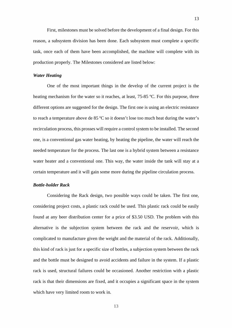
Water Heating
One of the most important things in the develop of the current project is the
heating mechanism for the water so it reaches, at least, 75-85 ºC. For this purpose, three
different options are suggested for the design. The first one is using an electric resistance
to reach a temperature above de 85 ºC so it doesn’t lose too much heat during the water’s
recirculation process, this prosses will require a control system to be installed. The second
one, is a conventional gas water heating, by heating the pipeline, the water will reach the
needed temperature for the process. The last one is a hybrid system between a resistance
water heater and a conventional one. This way, the water inside the tank will stay at a
certain temperature and it will gain some more during the pipeline circulation process.
Bottle-holder Rack
Considering the Rack design, two possible ways could be taken. The first one,
considering project costs, a plastic rack could be used. This plastic rack could be easily
found at any beer distribution center for a price of $3.50 USD. The problem with this
alternative is the subjection system between the rack and the reservoir, which is
complicated to manufacture given the weight and the material of the rack. Additionally,
this kind of rack is just for a specific size of bottles, a subjection system between the rack
and the bottle must be designed to avoid accidents and failure in the system. If a plastic
rack is used, structural failures could be occasioned. Another restriction with a plastic
rack is that their dimensions are fixed, and it occupies a significant space in the system
which have very limited room to work in.

14
14
In the other side, a personalized beer bottle rack can be design. This structure can
be adjustable for different major diameters and it allows to optimize space, quantity of
bottles used, and most important, the subjection systems will be designed especially for
the tank where the washing process will be performed in.
Piping System
The problem found with this design criterion is the Thermal Conductivity, Energy
and pressure losses which can appear in the fluid movement inside the pipes. Thermal
conductivity is one of the most important criteria to be considered during the design of
the project because, as said before, to meet standards, the machine should wash and rinse
bottles with water heated at 75-85 ºC. To reach this temperature, a water heating system
has to be designed. However, after this system heats the water, it must be able to maintain
the liquid temperature constant in order to meet the standards. For this reason, it is
important to appropriate choose the pipe’s material in order to maintain temperature and
reduce energy losses.
Also, it is important to consider the sanitary regulations that must be followed for
machine to operate in a food plant. Corrosion must be avoided as much as it is possible
to keep the security of the rest of the plant and to avoid contamination over the food and
the bottle’s surfaces. Two viable solutions are proposed: Design a piping system with
cupper pipes or stainless-steel pipes.
Considered all these factors, selection criteria were applied obtaining the results
showed in the following section.
Evaluation and Selection Concepts
To solve milestones found during the Beer Bottle Washer Machine design, the
following criteria are going to be considered to solve de different problems discussed in
previous sections.

15
15
Water heating
For this Milestone, the criteria taken in consideration are:
Operating Safety Cost, Precision, Operation safety, Weight.
For this, we’ve considered four different parameters to choose the best option por
the project:
Cost and precision are the most important parameters since this project has a limited
budget, and it must reach the stipulated temperature, and rack-pipe bottle alignment so
the cleaning process is effective.
Operation safety is the next most important parameter because high temperatures,
electric connections and chemicals will be managed during the machine operation.
System weight is the least important parameter since it has to me able to move around
without too much problems, but it is not as critical as the previous ones.
Considering all this information, a selection matrix has been built to help the
group choose from the different options presented to solve the water heating milestone.
Table # 26 allows to understand that the better option for the project, considering
all the parameters is a resistance heater. This is, by far, the best option among the three
others presented. In the other hand, the gain heater and the hybrid heater are very similar
options, after the analysis, the conventional water heater (gain heater) is considered a
slightly better option than a hybrid mechanism.
Beer Bottle Rack
For this Milestone, the criteria taken into consideration are:
Cost, Size, Precision, Weight, Operating Safety.

16
16
It is important to mention that Cost and Size are the most important parameters
for this case because the budget of the Beer Bottle Washer Machine should not exceed
the 300 USD, and the size of the rack should let it fit inside the tank without any problem
of blocking the piping system.
As shown, the best options to be applied is the design of the rack. One of the non-
analyzed parameters is the facility for the operator to manipulate the structure and the
design complexity. Concluding, it is better to adapt a new system to our specific design
than picking up an existent one.
Pipe Selection
For this milestone, four different parameters have been considered to help the
selection of the best option for the project:
Cost, Weight, Thermal Conductivity.
It is essential to mention that, as in the previous selection, cost is an important
parameter. However, in this case, there must be a balance between the loss of energy
during the process and the material cost. The project has two options for the material for
the pipe: Stainless steel and copper.
Table # 30 shows the best option for the pipe’s material is stainless steel because
its thermal conductivity will help the system conserve more thermal energy during the
water distribution. In the long run, a copper pipe would cause a big loss of thermal energy
generated in the heating process, only by heat transfer. Recall that copper has a thermal
conductivity of 401 W / (m · K), while stainless steel has a conductivity of 16.3 W / (m
· K).

17
17
Figure # 5: Final design of water heating system. Reprinted from
Alibaba 2020. https://www.alibaba.com/product-detail/High-
Resistance-Electrical-Coil-Stainless-
Figure # 3: Final design of the Rack
Figure # 4: Final design of piping and tubing system

18
18
Project Management
Activities Management
Due to the worldwide problem during the production of this project (coronavirus) a plan B has been made an adapted to meet as much of
the initial requirements as possible. Considering that physical development of the project won’t be carried out, all simulations, reports, calculations,
reporting and meetings have been changed to an online modality. The Table # 2 shows the calendar with the changes which took place throughout
this period, considering all development stopped on March 15, 2020.
Table # 2: Schedule of activities

19
19
Source: Smartsheet Inc. (2013)
20
Budget Management
This project, being a design that will be performed following the Ecuadorian food
industries standards, must be modeled of stainless steel. For this reason, costs increase
significantly and must have specialized treatment with first-class professional equipment.
Universidad San Francisco de Quito provides to the group 300 USD budget the
development of the project. However, an additional budget provided by the client is under
consideration. Also, each student who are part of the project is allowed to contribute with
a small budget to achieve the client’s requirement.
Due to the aforementioned, a quote has been made for the entire project, which
will be found in the Appendix B – Project Management. This quote can be discussed to
achieve lower costs and be adjusted to the group budget.
Engineering Standards
Considering the assemble, operational and design standards for the Beer Bottle
Machine Washer development have been considered. To select these standards, it is
important to consider safety, life-time operation of the system and internal regulations
given since the system counts with food grade components.
Stainless Steel managing
As mentioned into criteria selection method, stainless-steel pipes are going to be
used. According to The European Stainless-Steel Association, one of the most attractive
features of this material is its corrosion resistance. There is no chemical reaction between
the mentioned material with any kind of food. According to the Europe Framework
Regulation 1935/2004, stainless steel is one of the most reliable materials which does not
transfer constituents to foods in quantities that could endanger human health or could
bring an important change into the food composition. This same normative, recommends

21
the usage of AISI 304 material because of its versatility and tolerance to powerful
detergents (Partington, 2006).
The corrosion resistance property of this material comes from a protective film
with a chromium-rich oxide that avoid penetration of components into the base material.
The mentioned film is able to regenerate in case that the surface is penetrate or damaged
by a tool. Considering a hydrodynamic analysis, the roughness of this material has a very
low value which decreases the major losses into the fluid and avoids the pressure drops
that is important into the functionality of the Bottle Washer Machine. It is important to
mention it that this kind of materials has a wide range of temperatures frequently
encountered in the production of food, in the case of the bottle washer, the temperature
of the water or even the production of steam, will not affect to the life time of the pipes
and does not affect the drastic change of temperatures (Partington, 2006).
The construction of the Beer Bottle washer machine, will follow the design
principles of:
“The EC Machinery Directive 98/37/EC: 1998 [15] states that machinery
‘must be so designed and constructed as to avoid any risk of infection,
sickness or contagion". EN 1672- 2: 2005 [16] demands that a machine
must be ‘capable of being properly operated, cleaned and maintained’”
(Partington, 2006).
For the welding process, the same European standards are going to be followed,
this mentions the process has to be taken down into the welding of stainless-steel food
grade materials. Cleaning processes should be performed before and after the process,
this will avoid the presence of contaminants such as oil, grease, oil and different solvents.
Also, normative suggests, is recommendable, while working with stainless steel, not to
work in the same place with carbon steel materials because it could affect the carbon

22
particles of the base material and that’s a non-desired result for this process. Also, an
appropriate cleaning of the base material is necessary by using noncorrosive acids and
different brushes which will clean particles that may affect to the welding process.
Additionally, to avoid imperfections and the insertion of powders inside the material
during the cutting process, a laser cut process will be performed (Partington, 2006).
According to the normative, there are some recommendations to follow during the
process (Partington, 2006):
Molten metal must be shielded from atmospheric oxidation by means of a gas or
a slag or a vacuum to preserve optimum corrosion resistance.
Work by following the G211 normative to determine the state of the Heat Affected
Zone (HAZ).
During welding, execute sensitization process should be carried out by allowing
the formation of chromium carbide particles. This will avoid the combination of
chromium with oxygen to not affect the stainless-steel corrosion resistance.
Avoid great amounts of temperature gradients at the HAZ, this will prevent the
production of micro fissuring and cracks on the material.
For this machine construction, European standards will be used for managing the
stainless-steel. European community stablishes regulations for an adequate manipulation
and operation of this material, which after analysis, contributes more safety parameters
than the Americans regulations. The additional standards are:

23
Table # 3: European Standards
Food processing machinery
EN 1672-2; Food processing machinery
— Basic concepts — Part 2: Hygiene
requirements.
Tubes and pipes
EN 12502-4; Protection of metallic
materials against corrosion — Guidance
on the assessment of corrosion likelihood
in water distribution and storage systems
— Part 4: Influencing factors for stainless
steels.
NaOH safety data sheet: Handling and hazards
NaOH or commercially know as caustic soda, is chemical substance used in the
industry field. For this specific project, caustic soda is used to clean the glass bottles prior
its use to bottle up alcoholic beverages. Caustic soda is a very important component in
the bottle washing process. However, it also is a very dangerous chemical which should
be properly managed. According to LabChem’s safety data sheet, the following
instructions should be followed at all time to avoid any accident the chemical can cause
due to bad management.
24
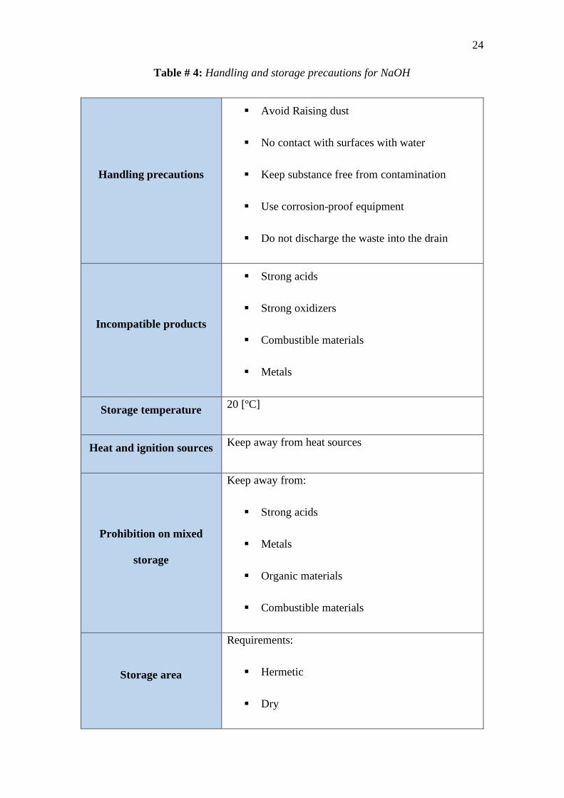
Table # 4: Handling and storage precautions for NaOH
Handling precautions
Avoid Raising dust
No contact with surfaces with water
Keep substance free from contamination
Use corrosion-proof equipment
Do not discharge the waste into the drain
Incompatible products
Strong acids
Strong oxidizers
Combustible materials
Metals
Storage temperature 20 [ºC]
Heat and ignition sources Keep away from heat sources
Prohibition on mixed
storage
Keep away from:
Strong acids
Metals
Organic materials
Combustible materials
Storage area
Requirements:
Hermetic
Dry

25
Corrosion proof
Well ventilated
Watertight
Packaging materials
Stainless steel
Nickel
Polyethylene
Paper
Avoid:
Lead
Aluminum
Copper
Bronze
Tin
Zinc
Textile
Source: LabChem’s NaOH safety data sheet
Also, it is important to understand the hazards the caustic soda means. The
following table shows the GHS-US labeling for the product:

26
Table # 5: Hazard information for NaOH
Hazard Pictogram
Hazard Statements
H314 – Material can cause severe skin and eyes injuries
H318 – Material can cause eye damage
H402 – Material is dangerous to aquatic life.
NFPA Pictogram
NFPA Statements
3 – Material cause serious damage and permanent
injuries
0 – Material will not burn under normal conditions
1 – Material is stable but can react under high
temperature and pressure
Personal protection
F:
Safety glasses
Synthetic apron
Dust respirator
gloves
Source: LabChem’s NaOH safety data sheet

27
If the complete information is needed see the ¡Error! No se encuentra el origen de
la referencia. - ¡Error! No se encuentra el origen de la referencia. for the entire NaOH
data sheet.
Stainless Steel Welding
“The welding process affects the mechanical and corrosion resistance properties
of both the joint and adjacent areas” (Euro Inox, 2006). The high temperatures of the weld
have consequences on the material, so the following recommendations given by the
author must be followed to reduce the effects on the material and obtain better results.
During the welding process itself, the molten metal must be shielded from
atmospheric oxidation by means of a gas or a slag or a vacuum in order to achieve
and preserve the optimum corrosion resistance and mechanical properties in the
joint.
During welding, chromium and carbon in the stainless steel can form chromium
carbide particles, a process known as sensitization. This reduces the chromium
available to combine with oxygen and so form the chromium oxide passive layer
which gives stainless steel its corrosion resistance. (Euro Inox, 2006)
On each side of the material, the HAZ (Heat Affected Zones) will form because it
will be brought to melting temperatures. These areas will be affected with respect to the
technique used in welding, carbon composition of the steel, filler materials and
subsequent chemical treatments
It is important to remember that high temperatures can distort the material and
generate high stresses during cooling, a feature of the welding process. In addition, it
should be mentioned that the weld can generate microcracks in the material.

28
“Welding is followed by cleaning. A ‘thermal tint’ will form around the weld
causing the thermal resistance to decrease” (Euro Inox, 2006). To solve this, the pickling
is carried out, which allows the controlled erosion of the weld and thus prevents oxidation.
MATERIALS AND METHODS
Material and Component Selection
The Bottle Washer Machine is going to operate with sodium hydroxide (NaOH) -
better known as caustic soda- and heated water during its operation. Sodium hydroxide
(NaOH) is a corrosive substance used for the manufacture of cleaning products such as
soaps, detergents and bleach (Chemical Safety Facts, s/f). However, in this case the
Washer Machine is going to help with the dissolution and cleaning of the beer and any
oil or grease remaining in the surface of the bottles. It is very possible that the use of
caustic soda and heated water is going to cause corrosion in the device’s material.
Corrosion is a destructive attack suffered by a material, usually metallic, by chemical or
electrochemical reaction with its environment (Gomez, 2004).
Moreover, the permanent exposure of the device against corrosive elements
suggest the use of materials that will not be affected by corrosion by its characteristics.
Stainless-steel contains chromium and nickel that give it these characteristics. “On the
surface there is a thin film of very dense chromium oxide that constitutes a shell against
corrosion attacks. If this chromium oxide film covering the stainless steels is removed, it
is re-formed immediately when chromium is combined with oxygen from the ambient
atmosphere” (Upcommons.upc.edu, s / f).
According to BRC standard, all the equipment using in food industry has to be
made of stainless-steel (Gomez, 2004). Furthermore, the use of corrosive fluids during

29
the operation of the machine imposes the use of Stainless Steel for the manufacturing of
the device.
Table # 6: Criteria selection for Stainless Steel
Stainless Steel < Copper
Cost analysis
CRITERIA Stainless Steel Copper E+1 Weighted
Stainless Steel 0 0 0
Copper 1 1 1
Total 1 1
DESIGN FOR MANUFACTURING
To apply the manufacturing design technique properly in the bottle washer
machine, the project was classified into 4 subsystems:
Piping system
Basket and transportation of the bottles
Water Heat subsystem
Reservoir tank

30
Piping System
This system has been optimized by different tests and the analysis of the
prototype (Figure # 2) developed before the final design of the system.
Figure # 6: PVC Prototype designed by the Client
The decision has been taken based on the following reasons:
The piping system has to be detachable for cleaning purposes.
Hot water has to going to be transported by the piping system.
No leaks should be present during operation.
The first one of the client’s requirements is that the system must be completely
detachable because the reservoir tank has to be used for other different applications. Also,
the client wants to be able to clean the tank and the entire pipe system following hygiene
standards over the industrial food plants machines.
Leaking problems can be avoided by using stainless steel as manufacturing
material. Also, this problem could be avoided by welding or flanged joints since.
Threaded joints are not an option because this joining method does not warrant an
effective joint between materials and serious bacterial outbrake in a long-term.
The weldability of the stainless steel makes it very viable option as base material.
Considering the high cost of this material other materials like PVC or allows the

31
manufacturer to distribute more money in other critical parts. However, as analyzed in
previous sections, stainless-steel properties like thermal conductivity, corrosion
resistance, weldability and taking into consideration industrial standards, make this
material the most eligible for the manufacturing process.
Water Heating Subsystem
The water heating subsystem was optimized by the analysis of the heat input that
the system needs and by the cost and effectiveness of the heat exchanger needed on the
water reservoir tank. For the heat input to the water two options have to be considered:
Electric water boiler and 4-Kilowatts stainless-steel resistances. The stainless-steel
resistances were selected even if more time will be needed to get to the desired
temperature of 85 ℃.
For the system, at least 2 resistances will be needed, each of them costs almost
100.00 USD which, compared to the boiler cost of 500.00 USD, represents a lower impact
to the project budget. Also, if the boiler is considered, the water will have to be reinjected
Figure # 7: Piping System Optimization

32
into the boiler pipe which will represent, beside the extra cost, an important pressure lost
during the machine operation.
Stainless steel resistances are well known for its effects against corrosion, and it
allows to occupy less energy than the boiler. The system operation temperatures can be
controlled by PLC’s using thermocouples and stablishing operation temperatures
constrains. A switch could be able to jump in case of an overheating. Also, it has to control
the power input to the electric resistances.
Figure # 8: Electric Resistances illustration. Reprinted from Alibaba, 2020,
https://www.alibaba.com/product-detail/Solar-Water-Heater-Immersion-
Coil_62007207589.html
Bottle-Holder Rack
The original rack model was a traditional commercial bottle basket which had a
PVC pipe water distribution system. This model with doesn’t count with good
ergonomics design and a correct bottle fasten method. A viable option has been
considered to assure the correct positioning of the bottles, precision, easy mobilization,
and stress resistance to the weight of the set of bottles.

33
The new model can hold twenty-four bottles per cycle during the washing process.
This new option is made of rods which form a rack to hold the bottles by their neck and
its base by means of elastic cables at the top as it is shown in Figure # 9. On the sides,
the rack has two handles so that it can be moved from the washing section to the rinsing
section. This model manufacturing requires cutting, bending and welding of rods with a
certain precision. The base rods are 7 [mm] while the internal rods will be 4 [mm]
Water Compartments
In the plant the washing process was done in a small plastic tank of around thirty
centimeters supported by a moving structure at the bottom. (Figure # 10a) The
ergonomics was uncomfortable for the operator and it didn’t follow any fabrication
standards so it can operate in an industrial food plant.
The U.S.F.Q industrial food plant provided the project a stainless steel tank shown
in the Figure # 10b. The tank has the correct dimensions so it can be divided into two
different compartments which will be transformed into the two washing stations
mentioned in previous sections.
Additionally, it is necessary to include pipe inlets with incoming ferrules for easy
assembly of the main pipe. Two liquid outlets have to be included in the base of each
Figure # 9: Basket optimization

34
compartment to drain the water and the caustic soda after when the washing process has
finished (Figure # 10c).
Figure #10c: Final Tank Optimization
Figure #10b: Stainless-steel Tank Figure #10a: Old bottle washer machine
Figure # 10: Tank Optimization
35
A detailed diagram was elaborated to show the sequence to follow to complete the
assemble of the bottle washing machine. The Table # 28 added into the Appendix B –
Project Management, Gaant Chart: shows each step to follow in order to complete the
correct assemble of each subsystem and how they connect to the final manufacture of the
entire system.
Each subsystem must be connected to the reservoir system with the purpose to
recirculate both fluids during the machine operation. There are two parts of the diagram,
the first one is the design, it is about the parts selection and the acquiring processes. The
second part is the production. It shows which steps must be followed to assemble each
subsystem and where and how they have to be connected into the final assemble. The
operator has to review the diagram after the assemble process. The machine must be
validated and tested before it is delivered to the client.
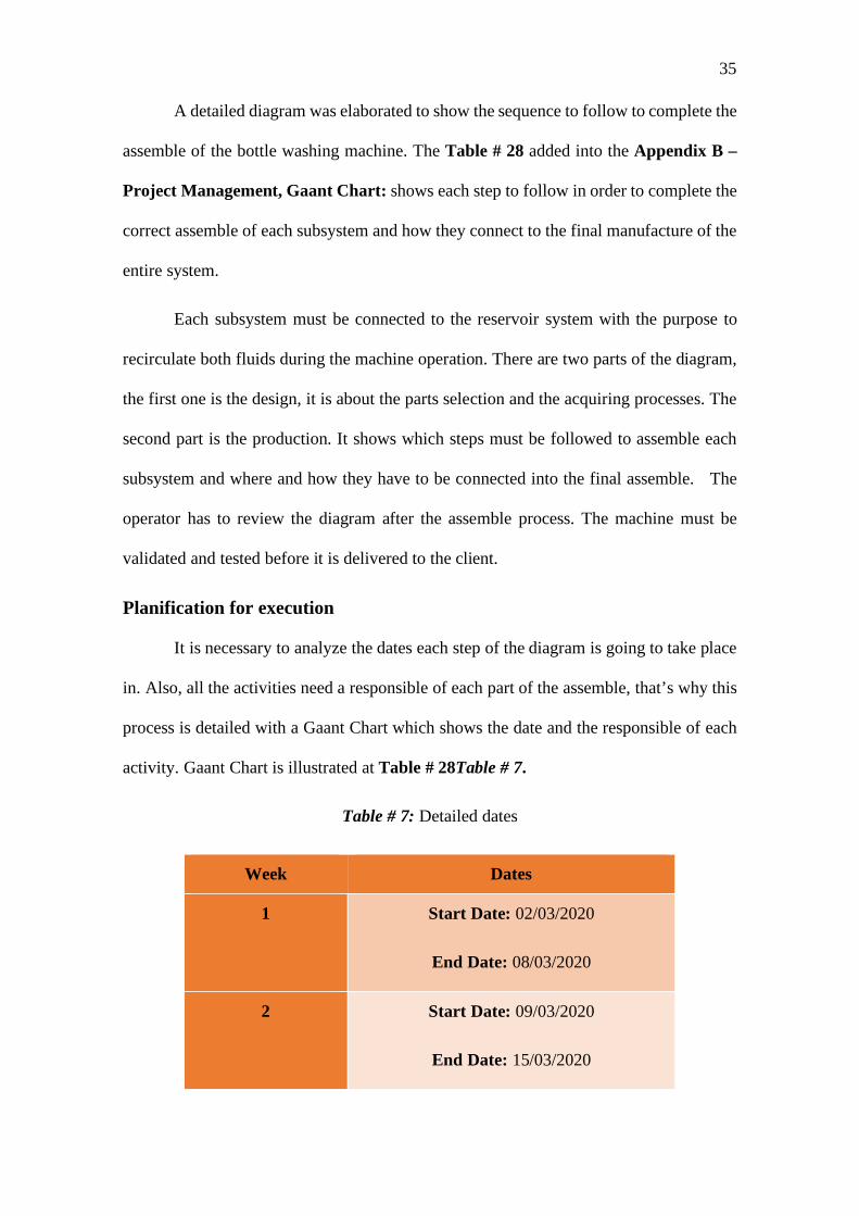
Planification for execution
It is necessary to analyze the dates each step of the diagram is going to take place
in. Also, all the activities need a responsible of each part of the assemble, that’s why this
process is detailed with a Gaant Chart which shows the date and the responsible of each
activity. Gaant Chart is illustrated at Table # 28Table # 7.
Table # 7: Detailed dates
Week Dates
1 Start Date: 02/03/2020
End Date: 08/03/2020
2 Start Date: 09/03/2020
End Date: 15/03/2020

36
3 Start Date: 16/03/2020
End Date: 22/03/2020
4 Start Date: 23/03/2020
End Date: 29/03/2020
5 Start Date: 30/03/2020
End Date: 05/04/2020
6 Start Date: 06/04/2020
End Date: 12/03/2020
Table # 7 illustrates the activities to be done and each responsible to complete
them. The black label corresponding to Fernandez/Moreno CIA LTDA, is the company
in charge to develop the stainless-steel welding because certified professionals are needed
for this task. This company has been chosen because its warranty offered, and the low
cost compared to other options analyzed
Table # 18 and Table # 19 contains details of all the parts which make up all the
piping and reservoir systems. The length and diameter tolerances are defined, and their
respective measurement instruments are mentioned. Finally, in the last column the
measurement responsible has been designated.
Table # 20 contains the pump specifications which will be used in both reservoirs.
The pumping system is designed to work with a flowrate of 99.6 [L/min]. A tolerance of
± 1 [L/min] has been defined given that the simulation verifies that this difference does
not affect considerably to the normal function of the bottle washing machine.

37
Table # 21 is composed by two sections which contains the different measurable
parameters and their corresponding measurement. Each of these components need to
control different parameters to warrant that the system is working correctly.
Finally, Table # 22 shows the part list for the pump controller, here, there are no
parameters to be measured given that this is just a control subsystem.
Quotation
As mentioned in previous sections, the budget is one of the most important and
limiting parameters for the development of the project. For this reason, is necessary to
mention the costs of each subsystem. Many quotations have been received; however, this
section will consider the most convenient ones considering costs, materials and warranty.
Piping System Costs
Table # 8: Piping system detail cost

38
Controller, Water Heating System and Basket costs
Table # 9: Detail Costs of basket, water heater and pump controller
Both costs lists come from the same company, Fernandez/Moreno CIA. LTDA.
This supplier was chosen because their offer of a 1-year warranty for welding failures,
installation mistakes, corroded materials, electrical factory failures and transportation.
Considering this supplier, the final cost of the bottle washing machine will be of 1942.68
USD including taxes.
Finally, once the entire system has been assembled, it is necessary to measure and
define if each process has been correctly done by applying success parameters. Each
success parameter will be analyzed according to each subsystem. A color scale has to be
defined to show the success level of the system.

39
Subsystem Description Success Indicator Indicators
Piping
System
This system must control:
Size of pipes (Tolerances)
Welding of joints (AWS G211
Normative)
Installation of fittings
Permeability (No fluid leaks)
Sizes, joints,
permeability
fittings are
correct
Sizes, joints,
permeability
fittings are
barely correct
Sizes, joints,
permeability
fittings are not
correct
Green: No corrections
Yellow: At least one of the parameters is
incorrect, needs corrections.
Red: The entire system is failing, it needs
to be totally repaired.
Water
Heating
System
This system must control:
Temperature (85℃± 3 ℃)
Relay system to stop the system if it
is overheating.
Increase or decrease temperature if
the system needs (automatic control)
Temperature,
relay and
automatic
control are
correct
Temperature,
relay and
automatic
control are
barely correct
Temperature,
relay and
automatic
control are not
correct
Green: No corrections
Yellow: At least one of the parameters is
incorrect, needs corrections.
Red: The entire system is failing, the
system does not reach to temperature,
relay system is not working and
temperature is not controlled, system must
be redesigned and reassembled.

40
Pump
This system must control:
Flow rate of 99.6 � 𝐿𝐿𝑚𝑚𝑚𝑚𝑚𝑚
� ± 1 � 𝐿𝐿𝑚𝑚𝑚𝑚𝑚𝑚
�
Low vibrations
No leaks when joined to the piping
system (Sealed)
Flow rate,
vibrations and
sealing are
correct
Flow rate,
vibrations and
sealing are
barely correct
Flow rate,
vibrations and
sealing are not
correct
Green: No corrections
Yellow: At least one of the parameters is
incorrect, needs corrections.
Red: The entire system is failing, excess of
vibrations on the system, fluids are leaking
in the joints and flow rate is not the
desired. Pump is not well installed, and
probably, the pump must be changed for a
different that accomplish with the desired
parameters.
Basket
This system must control:
Stable bottles when they are on the
basket.
No bending
Fit correctly on the reservoir tank
holders
Stability,
bending and
fitting are
correct
Stability,
bending and
fitting are
correct
Stability,
bending and
fitting are
barely correct
Green: No corrections
Yellow: At least one of the parameters is
incorrect, needs corrections.
Red: The basket is bending, the bottles
have no stability (Risky) and the basket
does not fit on the reservoir tank holders.

41
Pump
controller
This system must control:
Emergency stop button
Timer
Signal lights (green: when the
system is on; red: when the system is
off)
Stop button,
timer and
signals are
correct
Stop button,
timer and
signals are
barely correct
Stop button,
timer and
signals are not
correct
Green: No corrections
Yellow: At least one of the parameters is
incorrect, needs corrections.
Red: E-Stop is not working, signal lights
are incorrect and the timer cannot be
programmed, the system must be
redesigned and reprogrammed.
Table # 10: Success Indicator
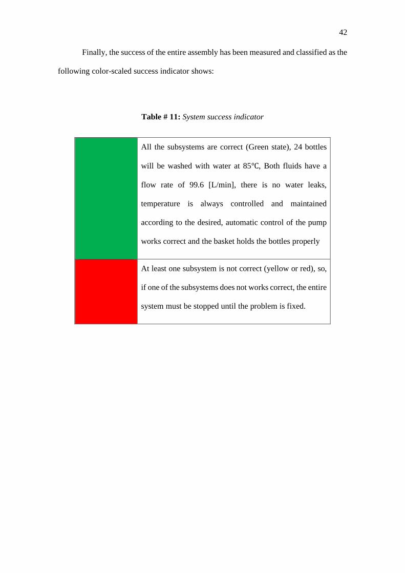
42
Finally, the success of the entire assembly has been measured and classified as the
following color-scaled success indicator shows:
Table # 11: System success indicator
All the subsystems are correct (Green state), 24 bottles
will be washed with water at 85℃, Both fluids have a
flow rate of 99.6 [L/min], there is no water leaks,
temperature is always controlled and maintained
according to the desired, automatic control of the pump
works correct and the basket holds the bottles properly
At least one subsystem is not correct (yellow or red), so,
if one of the subsystems does not works correct, the entire
system must be stopped until the problem is fixed.
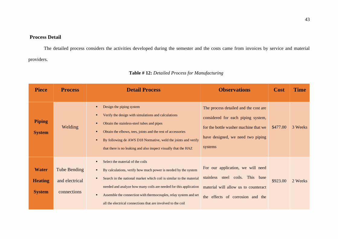
43
Process Detail
The detailed process considers the activities developed during the semester and the costs came from invoices by service and material
providers.
Table # 12: Detailed Process for Manufacturing
Piece Process Detail Process Observations Cost Time
Piping
System Welding
Design the piping system
Verify the design with simulations and calculations
Obtain the stainless-steel tubes and pipes
Obtain the elbows, tees, joints and the rest of accessories
By following de AWS D18 Normative, weld the joints and verify
that there is no leaking and also inspect visually that the HAZ
The process detailed and the cost are
considered for each piping system,
for the bottle washer machine that we
have designed, we need two piping
systems
$477.00 3 Weeks
Water
Heating
System
Tube Bending
and electrical
connections
Select the material of the coils
By calculations, verify how much power is needed by the system
Search in the national market which coil is similar to the material
needed and analyze how many coils are needed for this application
Assemble the connection with thermocouples, relay system and set
all the electrical connections that are involved to the coil
For our application, we will need
stainless steel coils. This base
material will allow us to counteract
the effects of corrosion and the
$923.00 2 Weeks

44
Install the heaters on the tank
Verify that the system works properly and test if the temperature
is the desired
system will last much time than
others like cupper or bronze.
Bottle-
holder
rack
Rods bending,
cutting
and welding
Select rack material
Design the basket with respect to the weight it will support
Obtain the rods according to the calculations obtained.
Cut the rod according to the plane measurements.
Bend rods to simplify weld joints
Weld the rods according to the plan and hooks that will hold the
elastic cord
Install the elastic cord in the basket with a proper fit
It is important to keep in mind the
precision of the measures of the mesh
of rods so that the neck of the bottle
is aligned with the nozzles of the
distributor tank. The basket must be
light so that it can be transported to
different places
$217.00 1week
Reservoir
Tank
Cutting
Welding
Cut and weld the plate dividing the tank
Cut and weld the pipe with the ferrules
Weld these pipes into the tank
Drill tank, the basket rods will enter these holes
Drill into the bottom of the tank for the water outlet. Put a cap
The welded pipe in the tank is made
of stainless steel and is used for the
entry and exit of fluids
$170.00 3 days

45
RESULTS AND DISCUSSION
Design Report
One of the requirements of the bottle washer is that it be removable due to cleaning
as it will indirectly be related to food. Due to this, sections and parts have been designed
for a better explanation.
Because the food engineering production plant has provided the project with
pipes, pumps and the tank, the design with its calculations has been developed based on
the dimensions of these elements and their capacities. The optimal conditions that the
pumps should work were obtained, this helped not to have shortage of water or soda due
to its circulation in the pipeline. In addition, it has been verified that the power and the
number of nozzles do not cause the bottles to come out of the basket
Pipelines
It is essential to section the piping system that will recirculate the water and soda
since this will allow to thoroughly clean each of the parts. The material used for the
elaboration has been stainless steel for its resistance to corrosion and thermal insulation
compared to other options such as PVC pipes or hoses. This pipe will be made with an
outer diameter of 1in and a thickness of 2mm. The ends will have ferrules that will help
the coupling between them through clamps

46
Figure # 11: External pipes
External Pipes
The internal pipe is made up of two pipes. Internal pipe # 2 is similar as external
pipe # 2. These pipes are also called elbows and are the same dimensions for easy
handling at the time of assembly and disassembly.

47
Figure # 12: Internal pipes
The ferrules have a standardized form since they must be adjusted by clamps that
are equally standardized, so measures already established by the manufacturers will be
used. Ferrules will be welded to the ends of the pipes. Gaskets are used that prevent fluid
from escaping from the pipes. The design of the ferrule is as follows:
Figure # 13: Ferrule model standard

48
Figure # 14: Ferrule design standard
The water distribution piping has been designed with stainless-steel tube provided
by the customer. The pipe dimension is 1-inch external diameter and 2mm thick. The
design was made to clean twenty-four bottles at the same time. The position of the holes
is important because they must be correctly aligned to the necks of the bottles (Figure #
15). Nuts will be welded to the water outlet holes so that the nozzles can be screwed .
Figure # 15: Water distributor model
The customer has provided with the tank to modify it. The Figure # 16b shows
the tank before its modifications and in the Figure # 16a and a 3D model of this design

49
can be viewed. A stainless-steel plate will be welded in half to separate the soda and water
processes. On the sides, the pipes for the exit and entrance of fluids will be cut and
welded, this also allows the pipes to be demonstrable and cleaning can be carried out
without any obstacle. It is important to make a hole and place a plug at the bottom to
expel the used water. These dimensions are important because we need to calculate the
volume of water the machine is going to use, even it helps us to model the frame of the
basket. (Figure # 16a)
Figure # 16: Changes made to the Tank. Left, before
changes. Right, after changes.

50
The basket was designed for cleaning 24 bottles. This contains a mesh made by rods to
insert the bottle neck at the base of the basket and at the top there is a mesh of elastic
cables that allow the holding of different sizes of bottle bases. On the sides there are
handles that allow you to lift the basket and remove it. At the lower corners there are 4
rods that allow the basket to be inserted into 4 holes that contain the tank and thus prevent
it from moving. It is important to know the dimensions of the bottle because the
dimensions of the basket depend of what kind of bottle are being used (Figure # 18). The
dimensions are the following:
Figure # 17: Tank Design

51
Figure # 18: Dimensions of the bottle
Figure # 19: Basket model
The inclusion of the nozzles was important since it allows the direction of the
water jet and to have a better cleaning. The valves included in the tank are for a 1 1/2 in

52
diameter pipe (Figure # 22). Pumps have also been supplied by the customer and are 1HP
and 1 / 2HP each (Figure # 20 and Figure # 21)
Figure # 20: Pump ½ HP
Figure # 21: Pump 1 HP

53
Figure # 22: Valve model
The Figure # 23 shows the final model CAD in Inventor Software. A stainless-
steel plate is welded in the middle of the tank to divide it in two and carry out the process
with water and caustic soda in different sections. Different models and options have been
analyzed in order to reduce expenses due to the high cost of stainless steel and its
machining.
Figure # 23: Washer Bottle Final Model
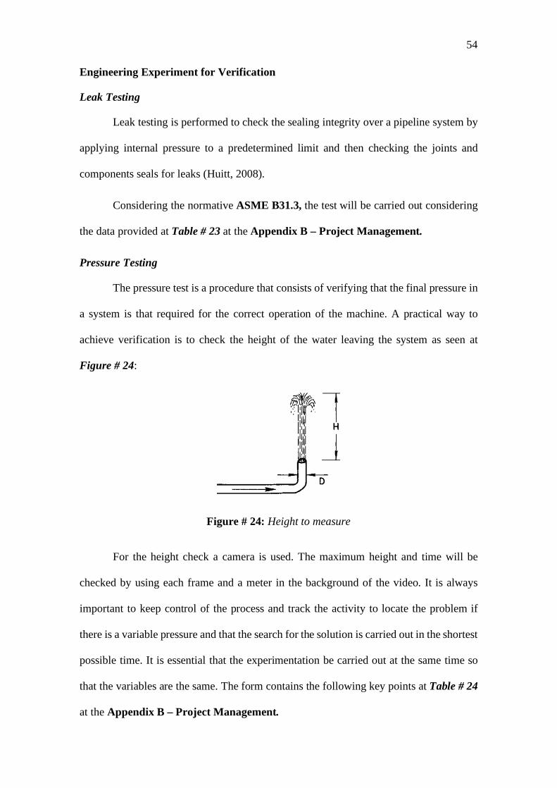
54
Engineering Experiment for Verification
Leak Testing
Leak testing is performed to check the sealing integrity over a pipeline system by
applying internal pressure to a predetermined limit and then checking the joints and
components seals for leaks (Huitt, 2008).
Considering the normative ASME B31.3, the test will be carried out considering
the data provided at Table # 23 at the Appendix B – Project Management.
Pressure Testing
The pressure test is a procedure that consists of verifying that the final pressure in
a system is that required for the correct operation of the machine. A practical way to
achieve verification is to check the height of the water leaving the system as seen at
Figure # 24:
Figure # 24: Height to measure
For the height check a camera is used. The maximum height and time will be
checked by using each frame and a meter in the background of the video. It is always
important to keep control of the process and track the activity to locate the problem if
there is a variable pressure and that the search for the solution is carried out in the shortest
possible time. It is essential that the experimentation be carried out at the same time so
that the variables are the same. The form contains the following key points at Table # 24
at the Appendix B – Project Management.

55
This method is very effective and practical since high technology is not required
for the measurement. A cell phone camera, a meter and analyzing each frame is enough
to verify if there are pressure drops and therefore height differences.
In this system, it is necessary to take man tests to ensure that the pressure has not
varied. The height at which the jet must reach is 2 meters above the nozzles.
Prototype Test Plan
The test plan will be performed for each design constrains purposed in the project.
There will be 6 different engineering criteria to be analyzed in the test plan, these are:
pipe and bottle-holder rack dimensions, bottle holder rack stress test, flowrate test,
pressure test at the nozzles, fluid temperature at the reservoir and the nozzles, time of
operation test. Each test will be performed in the same order as it was mentioned. To
advance to the following test, the previous one has to be approved following the criteria
detailed in the sections bellow. The Table # 13 shows the acceptable values each criterion
should have to be approved
Table # 13: Engineering criteria and test plan requirements
Engineering Criteria Acceptable values
Pipe and bottle-holder rack dimensions test
The tolerance for pipe length is ± 5 [mm] and for
its diameter ± 1 [mm]
The tolerance for the rack and the distributor dimensions is ± 1 [mm]
Bottle-rack stress test
The rack should resist a load of 20 [kgf] symmetrically distributed independently at the top and at the bottom of the structure. If possible, to perform, the structure should resist a stress 20 [MPa] in compression in the universal test machine.
Flow rate test Main Pipe
Minimum: 170,23 [l/min] Maximum:170,23 [l/min]
Distributor pipe Minimum:15,59 [l/min] Maximum:26,48 [l/min]

56
Pressure test Main Pipe
Minimum:0,221 [KPa.g] Maximum:50,904 [KPa.g]
Distributor pipe Minimum: 0,006 [KPa.g]
Maximum: 0,065 [KPa.g]
Fluids temperature test At the nozzles the fluid temperature should be
within 60-80 [ºC]
At the top of the reservoir the fluid
temperature should be within 70-90 [ºC]
Time of operation test The machine should operate during 5 complete cycles each one of 10 minutes. The operation time should be
60 [min] non-stop working.
Pipe and bottle-holder rack dimensions test
The piping system includes two subsystems, the first one is the main pipe (Figure
# 12) which connects the everything from the pump to the distributor pipe (Figure # 15).
The main pipe length dimensions are not as critical as the distributor pipe, this is why the
tolerance for the main pipe’s accessories length is ± 5 [mm]. The inner pipe diameter has
to be 1 [in] or 25,4 [mm] since there are an important number of accessories to be attached
to each other along the mine pipe, it is important that they fit as exactly as possible
therefore the diameter tolerance for the entire pipe system is ± 1 [mm].
The rack ant he distributor pipe should be as precise as possible because the each
bottle top, hold upside down by the rack, has to fit in with each nozzle in the pipe, if any
dimension differs by a more than a couple millimeters, part of the nozzles would be
pointing outside the bottle and this could produce the hot water is sprayed everywhere
causing serious problems and even injuries to the operator. For this reason, a ±1 [mm]
tolerance is applied to the system.
The dimension test consists in perform 10 different length and diametral
measurements with a caliper and a measuring tape to each accessory for the entire piping
system. This amount of measurements will prevent or decrease to a minimum the human

57
mistakes during the process. If any of the accessories doesn´t meet the stablished
tolerance it should be reported to the manufacturing manager, so it is appropriately
rectified or re-manufactured. If all the items are correctly measured and approved within
the tolerance measurement, the test can be considered as successful.
Bottle-holder rack stress test
The bottle-holder (Figure # 19) has to holds a maximum of 9,36 [kg] under
normal operation conditions. This includes the weight of 24 12onz. - beer bottles. For the
test a minimum safety factor of 2 will be applied. The test consists in apply 20 [kg] of
total weigh first symmetrically distributed in top side of the rack and then applied the
weigh hanging in the bottom side of the structure. The system should hold both
distributions type without suffering any permanent deformation or any indicator of cracks
in the material or the welding joints.
If an indicator of failure is detected, the rack should be analyzed for manufacturing
mistakes and rectified if possible. Otherwise, the structure has to be remanufactured and
re-tested until the visual results are satisfactory enough to be consider a successful test.
The rack can be tested also in the universal test machine in the mechanical department of
the U.S.F.Q applying a total stress of 20 [MPa] in compression in the middle of the
structure, under the same conditions of approval mentioned before. The test will be
performed only if the rack can be fitted inside the machine and can be placed in the correct
position for the test.
Flow rate and pressure test
The flow rate and pressure test will both consist in analyze the data given by the
corresponding measurement mechanism installed in different sections of the washing
machine. The pipe system will have two zones of flow and pressure measurement. Within

58
the main pipe and the distributor pipe a pressure gauge and a flow meter will be installed.
Then, the system will have a total of two of each of these mechanisms. The first pair
(pressure gauge and flow meter) will be installed along the main pipe. The second pair
will be installed at the farthest points of the distributor pipe, taking its center as the origin
point. Since the distributor has two equal distance points, each one of those will have one
measurement mechanism either a flow meter or a pressure gage.
For the main pipe, the pressure gage will constantly give a value which should be
within the 0,2 and 51 [KPa] or 0,3 and 7,4 [psi] (common units used in pressure gauges).
For this test, a simple gauge check during operation will be enough to assure the
mechanism is operating correctly. The pressure value will oscillate according to the
gauge’s location, if it is located near the pump, the value should be closest to the 7,4 [psi].
However, if the gauge is near the distributor, the value measured should be close to the
0,3 [psi]. This same methodology is applied to the distributor gauge. However, since the
location of it is specified to be at the farthest point from the center the value it should give
should be close to 0,0008 [psi] (0,006 [KPa]) this value can’t be higher than 0,01 [psi].
If the measurements are within the given values, the test is successful otherwise
maintenance may be necessity to fix the possible problems
The flow rate in the main pipe should remain constant at approx. 170 [l/min] so
the flow meter should always mark this value with a tolerance of ± 5 [l/min]. In the
distributor, considering the flow meter will be located at other of the farthest points in the
mechanism, the value should be close to 16 [l/min] and in cannot get higher than 27
[l/min]. If the flow meter gives values too low or too high than the minimum and
maximum values, the machine should be analyzed during maintenance to find and fix the
possible problem.

59
Fluids temperature test
There are two liquid temperatures to test: the fluid temperature at the top of the
reservoir tank and the temperature at the distributor pipe which will, approximately, the
temperature at the outlet if the nozzles. The temperature in the first scenario should be
within 70-85 [ºC] this temperature will allow the liquid, water or caustic soda, to be at an
acceptable temperature at the outlet of the pipe distributor which should be around 60-85
[ºC] depending of the fluid.
For the first case, the test will consist in measure the temperature with an industrial
thermometer, if the temperature is the acceptable the test will be successful. Otherwise
the preheating procedure and the heating components will be analyzed to find where the
problem is so it can be fixed.
For the second scenario the test will involve a more complex method, since a
thermocouple should be installed a one on the farthest points from the center of the
distributor point. This is with the intention to measure the temperature at, what is
supposed to be, the coldest point in the system. The thermocouple should be installed
during the manufacturing process and must be adapted in the control system. The validity
of the test will be proven with the same criteria mentioned before. This test, as the flow
rate and pressure test, has to be done every time the machine will be operating since these
are very important parameters for each cycle
Time of operation test
The machine has to operate during a minimum of 5 cycles when used. Each
washing cycle occurs during two phases caustic face and the rising face, both faces are
the same procedure using different liquids, caustic soda and water respectively. The
cycles in each phase will last 5 minutes of operation. The operation test will consist in
stress the machine to it maximum operation capacity during 10 to 15 minutes, during the

60
operation the system shouldn’t present any irregularity. After the operation each system
will be analyzed to find overheating, leaks, or any component damage. If the system is
without any damage, the test will conclude as successful. Otherwise, the damage
component will be analyzed, the causes of failure studied, and the part will be changed if
needed. Once the problem has been solved, the test will be performed again with the same
failure parameters.
Table # 14: Specific parameters vs test plan to validate them
Requirement Test to apply
All elements length dimensions should be within a
10 [mm] tolerance according to the drawing’s
dimensions.
Pipe and bottle holder rack dimensions
test.
All pipes diameters should be within a 1 [mm]
tolerance according to the drawing’s dimensions.
Pipe and bottle holder rack dimensions
test.
The bottle holder rack should resist a 20 [kgf] load
without presenting important or permanent
deformation
Bottle-rack stress test
The flow meter in the main pipe should mark a
value of 170 [L/min] while operating at its
maximum capacity.
Flow rate test
The flow meter in the distribution pipe should
mark a value between 15-27 [L/min] while
operating at its maximum capacity.
Flow rate test

61
The manometer in the main pipe should mark a
value between 0,2-51 [KPa.g] while operating at
its maximum capacity.
Pressure test
The manometer in the distribution pipe should
mark a value between 0,006-0,07 [KPa.g] while
operating at its maximum capacity.
Pressure test
The industrial thermometer at the tank should mark
a value between 85-90 [ºC] Temperature test
The thermocouple in the distribution pipe should
mark a value between 75-85 [ºC] Temperature test
The machine should operate for one hour or an
equivalent of 5 cycles time non-stop and should
not present any signal of misfunction.
Operation time test

62
Safety Through Design
Safety during the process is very important, it doesn’t matter if it is in the beginning
of the design of the mechanism or at the operating process safety should be always present
in every engineering procedure. Therefore, this project took into consideration a list of type
of risks with their own specific one that may affect one way, or another the system developed.
There are many types of risks to be consider in every project, but for this one in in
particular the list is reduced into six types that could affect different procedures involved in
the project. These types are listed below:
Economic resources
Security
Legal
Technical
Environmental
Operative
For each one of these two to three specific risks are applicable to be analyzed and
mitigated so they can be prevented to happen. For every risk the analysis classifies depending
on two parameters, the probability and the gravity or impact that the risk may have. For each
parameter are five sub parameters for better understanding (very low – low – medium - high
– very high) each one of these rated from one to five respectively. Multiplying both
parameters previously described, with the number given to each one of their sub parameters
is possible to quantify the value of the risk being 1 the lowest and 25 the highest. The next
figures help shows, in a better way, the previously explained with a color scale for each sub
parameter:

63
Table # 15: Value of risk quantified by the relation probability - impact of risks
Figure # 25: Color scale of value of risks

64
After the analysis of the 12 specific analysis listed in the figure below there was found
that most of the risk have values of 20 to 25 which represent very serious risks. However,
there are types of risks that should be consider priority over the other ones. For instance,
security and environmental types of risks are, for this project, more critical than legal or
technical problems. This is because these can affect directly to people or environment's
health. For this kind of risks the solution is to follow the respective procedures that rules this
kind of operations. Also, a good management of dangerous compounds, also ruled by certain
international regulations can help mitigate these risks. For security and technical risks related
to the procedure itself something so simple like using the respective safety equipment and
implementing safety devices to the prototype like an emergency stop button can help
eliminate very serious risks like injuries, electric or chemical risks. The Table # 16 shows the
risk analysis in detail.
Security risks have been the principal consideration during the machine design. The
system should operate with the maximum precisions as possible since it will operate with hot
fluids and electrical components. For these reasons, the design has been made do the bottles
will be well secured during operation and the nozzles can be fixed inside each bottle, so the
fluids jet won’t be splashed dangerously outside the machine. Also, both compartments in
the tank are design to have a maximum of 84 liters (40 cm height inside de tank) so the
liquids won´t spill.
Economic resources were another of the risks for the machine development. The
machine will operate according to alimentary operational standards, so it has to be built with
stainless-steel, an expensive material. Also, al the manufacturing processes involving this
material are just as expensive. The budget fixed for this project wasn’t enough even with a

65
very economical design. For this reason, in case of the development of the machine, a
minimum of 2000 USD are necessary for good results.

66
Table # 16: Color scale of value of risks

67
Results, Discussion and Conclusions
Pipe simulation results analysis:
The pipe system simulation is very necessary to fully understand the behave of the
system and to validate the design made before so this way the suppositions made are
verified or corrected if needed. For the simulations of both piping systems, the water
distribution system and the caustic soda (NaOH) distribution system, the software
Pipeflow was used. This program allows the user to make the piping circuit which, in this
case, each one has all the components which are incorporated in a real.
Overall System Analysis:
As mentioned before, the piping system will be exactly the same for both of the
washing machine parts. The only difference between the systems will be the liquid they
will operate with (water and caustic soda). The system has all the components specified
before in the design section such as the tank, pump, valves, elbows, tee’s, nozzles, joints,
and the pipe itself. The mentioned circuit is shown below:

68
Figure # 26: Piping circuit for simulation in Pipeflow.
The first simulation was made for the water system taking into account the parameters detailed in Table # 31. This simulation ends up in a big
change for the pumping system. The pump available and used for the design and calculations (provided for the U.S.F.Q) is overqualified for

69
operation purposes. In other words, the dimensions and the volume needed by the system to operate is too small for the pump. The Figure # 26
shows the operation point of the system using the properties of this pump.
Figure # 27: System curve overload with the 1HP pump performance curve and operation point of the system.
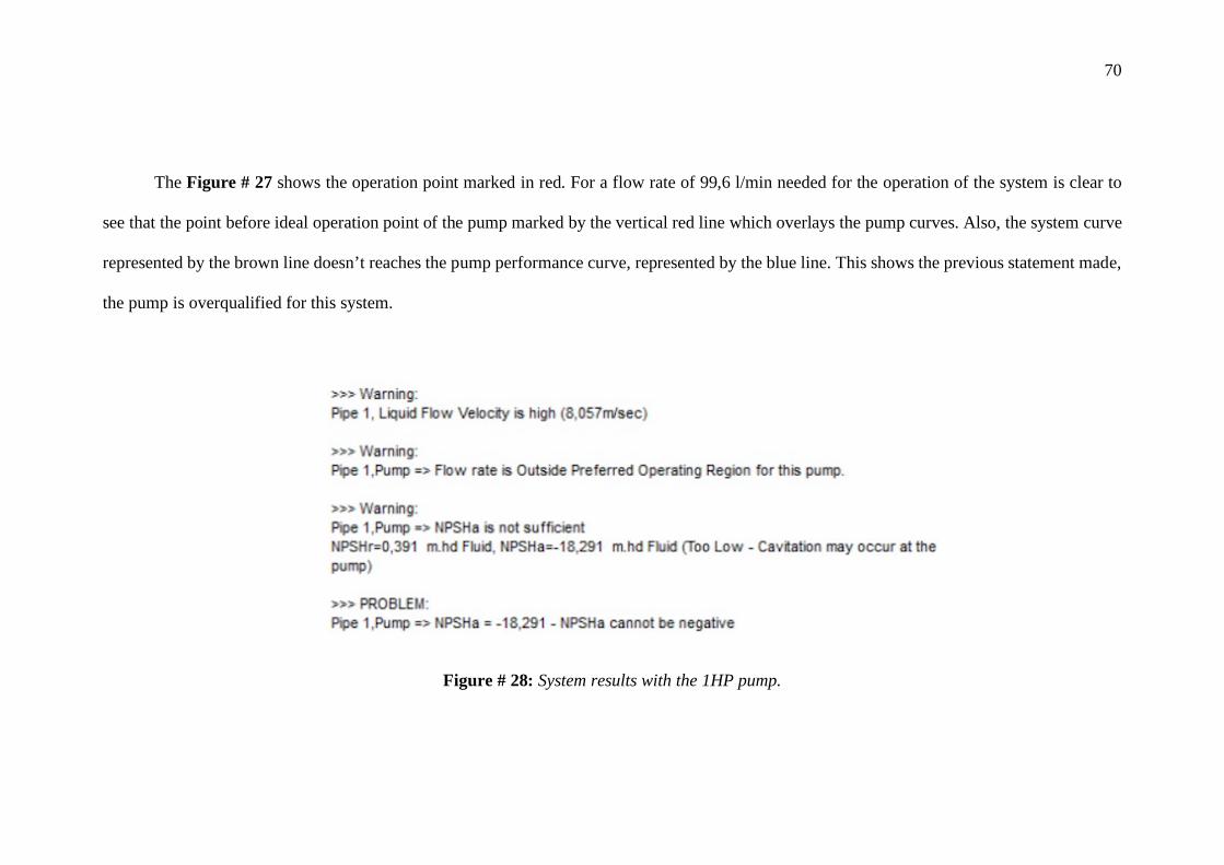
70
The Figure # 27 shows the operation point marked in red. For a flow rate of 99,6 l/min needed for the operation of the system is clear to
see that the point before ideal operation point of the pump marked by the vertical red line which overlays the pump curves. Also, the system curve
represented by the brown line doesn’t reaches the pump performance curve, represented by the blue line. This shows the previous statement made,
the pump is overqualified for this system.
Figure # 28: System results with the 1HP pump.
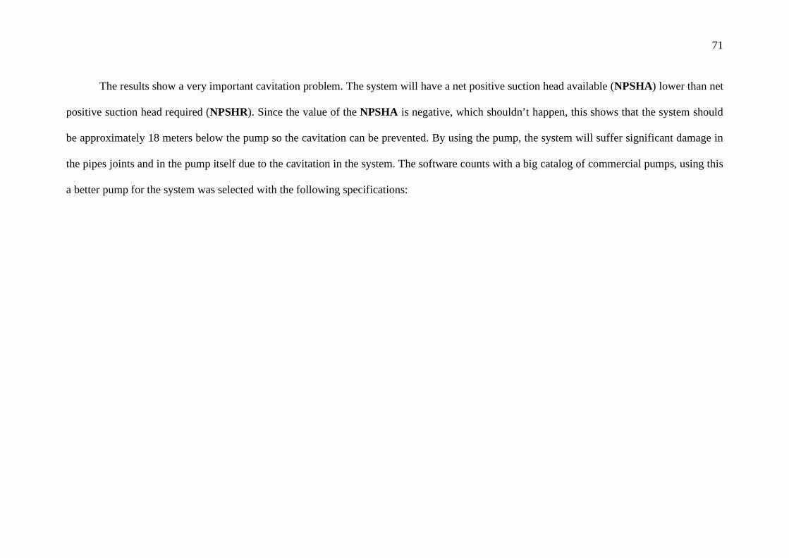
71
The results show a very important cavitation problem. The system will have a net positive suction head available (NPSHA) lower than net
positive suction head required (NPSHR). Since the value of the NPSHA is negative, which shouldn’t happen, this shows that the system should
be approximately 18 meters below the pump so the cavitation can be prevented. By using the pump, the system will suffer significant damage in
the pipes joints and in the pump itself due to the cavitation in the system. The software counts with a big catalog of commercial pumps, using this
a better pump for the system was selected with the following specifications:

72
Figure # 29: Re-selected pump specifications.

73
Water piping system simulation results:
With the new pump selection, a good simulation with very acceptable results was obtained. The needed flow is still the same of 99,6 l/min.
With the same dimensions and specifications of the pipe system except for the pump the result is show in the figure below.
Figure # 30: System curve overload with the re-selected pump performance curve and operation point of the system for the water piping.

74
This show a better system performance, the selected pump curve in blue overlays
with the system curve in brow in a very acceptable point. For this point the system work
with 51,84% of efficiency. Since the pump is working with a flow of 170,23 [l/min.], a
higher flow than the minimum required (approx. 15 [l/min.]) and a higher flow than the
flow rate needed, the pump selected is very adequate for the system. Having a higher flow
that the required is not a problem for this system because of the regulation valve the
system has and because a higher flow rate at the beginning represent a higher flow at the
exit of the nozzles and this causes no problem in the system. The head of 7,5 [m] obtained
in the simulation is far more acceptable for the system than the almost 45 [m] obtained
using the overqualified pump.
The other results of the simulation show that the cavitation problem present before
has been completely corrected since the system will have a net positive suction head
available (NPSHA) of 8,07 [m] this is higher than net positive suction head required
(NPSHR) obtained of 0,629 [m]. This proves once more that the re-selected pump works
in a very acceptable rage of performance for the system. Also, the results of flow rate,
pressure, and velocity in the farthest nozzle therefore more critical ones are: 0,43 [l/min],
0,026 [kPa], and 0,195 [m/s] respectively. These values represent acceptable results than
the ones obtained with the 1 HP pump for the nozzle requirements because these were
too high for the small dimensions of the system.
Caustic soda piping system simulation results:
For the caustic soda de need flow rate is the same of 99,6 l/min. The piping system
and dimensions and criteria of indicial temperature and pressure are still same as the ones
specified for the water.

75
Figure # 31: System curve overload with the re-selected pump performance curve and
operation point of the system for the caustic soda piping.
The figure shows that the re-selected pump works, for the caustic soda piping
system as acceptable as for the water system. The pump curve in blue overlays with the
system curve in an operation point of a flow rate of 151 [l/min.] and a head of 7,97 [m].
Very similar results than the obtained for the water system. This shows that the same
pump can be used in both systems in the washing process. At the point of operation, the
procedure has an efficiency of 50,72 %, a very acceptable value for the operation.
The other results of the simulation show that the cavitation won’t be a problem in
this system either. The system will have a net positive suction head available (NPSHA)
of 7,977 [m] this is higher than net positive suction head required (NPSHR) obtained of
0,607 [m]. This also proves that the pump selected is adequate for the whole piping
system in the washing machine since it operates good with both fluids water and caustic
soda providing a flow rate higher that the required and having no problems of cavitation.
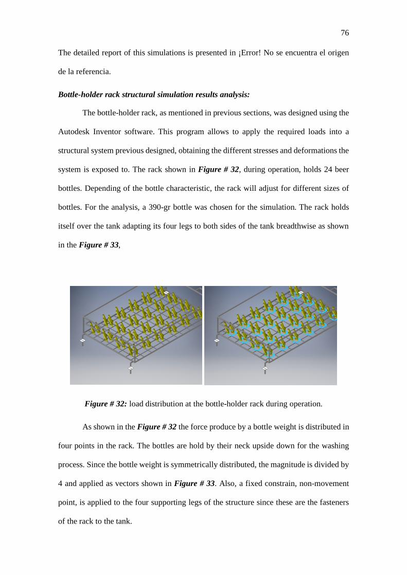
76
The detailed report of this simulations is presented in ¡Error! No se encuentra el origen
de la referencia.
Bottle-holder rack structural simulation results analysis:
The bottle-holder rack, as mentioned in previous sections, was designed using the
Autodesk Inventor software. This program allows to apply the required loads into a
structural system previous designed, obtaining the different stresses and deformations the
system is exposed to. The rack shown in Figure # 32, during operation, holds 24 beer
bottles. Depending of the bottle characteristic, the rack will adjust for different sizes of
bottles. For the analysis, a 390-gr bottle was chosen for the simulation. The rack holds
itself over the tank adapting its four legs to both sides of the tank breadthwise as shown
in the Figure # 33,
Figure # 32: load distribution at the bottle-holder rack during operation.
As shown in the Figure # 32 the force produce by a bottle weight is distributed in
four points in the rack. The bottles are hold by their neck upside down for the washing
process. Since the bottle weight is symmetrically distributed, the magnitude is divided by
4 and applied as vectors shown in Figure # 33. Also, a fixed constrain, non-movement
point, is applied to the four supporting legs of the structure since these are the fasteners
of the rack to the tank.

77
Figure # 33: Load magnitude applied to the bottle-holder rack during operation.
The calculation made in previous sections show a 2D structural analysis for one
of the many beams the rack has, submitted to the most critical scenario which is that the
entire weight of the bottle is hold in just one point of one beam and not in the 4 points
mentioned before. The calculation gave a stress due to the momentums and the different
forces applied to the beam. However, comparing a stress applied on a certain axis with
the yield strength of the material may not be precise enough for determining if the
structure will resist or not the given operating conditions. This is why the Von Mises
stress (𝝈𝝈′) is very important since it analyses the stresses considering volume and angular
distortions this makes this magnitude a very good indicator to be comparted with the
material yield strength (𝝈𝝈𝒚𝒚) knowing that if 𝝈𝝈′ > 𝝈𝝈𝒚𝒚 the design is good and it will resist
the operation condition. Otherwise, the system will experience failure and it is not a good
design for the needed conditions. This allows to give a bigger and more specified result
based on micromechanical principles and energy models to determine if the experimented
forces will produce stresses which will or will not cause failure.
Once the parameters have been specified the simulation can be performed and
analyzed. First, the Von Mises stress, which is an indicator of good or bad structural
design in the failure theories is shown by a magnitude and a color scale on the structure
as a visual interpretation of the stress along the structure in Figure # 33. The simulation
gives a maximum Von Mises stress of 18,11 [MPa] which compared to the yield strength
of the material of 205 [MPa] gives safety factor of approximately 11 ul.

78
Figure # 34: Von Mises stress at bottle-holder rack during operation
The calculation and the simulation both give the same conclusion, the structural
system of the project won´t represent a critical criterion for the design. The calculation
showed a stress of approximately 33 [MPa], in the more critical operation scenario, which
compared with the same yield strength as before gives a safety factor of 6 [ul]. As
mentioned before this may be not a good enough failure indicator for the system. That is
why the simulation and the Von Mises factor showed before are important, this allows to
validate or discard previous assumptions made in the process. However, both safety factor
obtained are acceptable for the project and leads to the same conclusion mentioned before.
The difference between the magnitudes are because of the type of analysis, in the
calculations the system taken was just a small part taken as critical. The simulation took
into consideration the entire system into normal operations conditions and assuming the
design will be manufactured as precise as possible. Even though both analyses are
different considering precision and criticality, those results still represent a very good
design for the structure.

79
Another good parameter to validate the structure design is the deformation
suffered during normal operation conditions. The Figure # 34 shows the displacement of
the structure under the conditions previously exposed. The maximum deformation is
located at the center of the structure with a magnitude of approximately 0,17 [mm] a very
small deformation and an acceptable one since it won’t be critical enough to deform the
location of the bottles in the nozzles for the washing process. Since the structure will be
operating within acceptable failure indicators and the stress don’t exceed the yield
strength of the material, any deformation in the structure caused by the operation
conditions previously exposed won’t exceed the plastic deformation regions.
Figure # 35: Deformation at bottle-holder rack during operation.
Future Work
Once the system has been virtual animated, the drawing has been approved by
professionals, and the results of the simulation indicate that a physical system can be
reproduced successfully with acceptable safety factor for each subsystem: liquid heating,
structural, and piping system; the construction of the actual bottle washer machine is one
of the two steps missing in the project. With the supplier’s price for the respective

80
manufacturing processes and with the international standards for these procedures, once
the first prototype is assembled, the system can be tested to verify it meets the Ecuadorian
alimentation industries standard and the international mechanical standards for the
machine to operate.
The second procedure to perform and according to the previous one, the machine
has to be tested to meet the client needs and criteria. The prototype’s test plan has to be
performed entirely to certify that all the parameters analyzed are within the tolerance
proposed in the project: pipe measurements, fluids temperature, flow rate, pressure,
weight tests and time of operation. Depending of the results given by this test plan, the
project could be either approved for delivery and installation to the costumer or revised
in case one or more of the parameters don’t meet the specified condition of operation. If
a failure is detected, the test plan for the corresponding system correction has to be
followed
Once the machine is installed, the customer has to be trained for a correct usage
of the machine, taking into consideration all the procedures and security equipment
detailed in the manual. The machine has to be in operation during three months before
the first maintenance is done, this one is for verification purposes analyzing how the
machine will behave in a long-term operation. The client will be provided with every tool
and procedure explanation for the correct maintenance of the machine. As a group
responsible of the development of the machine in every aspect, all the members are in
obligation of provide the respective solution for any problem presented with the machine
within one year after its installation.
For future projects like this one, is important to take into consideration the delicate
the system must be in terms of following manufacturing and operational standard since it
will operate within the alimentary industry. Also, is important to notice, for the same

81
reason, the materials a machine like this has to use are very expensive and it is very hard
to find some ways to decrease costs for materials or manufacturing process without
prejudice the long-term operation of the system. This is why a medium to big budget is
needed for this kind of projects, depending on how important and precise the process has
to be different ways to approach some subsystems, like the liquid heating system for
example
82
References
Alibaba. (2020). Solar Water Heater Immersion Coil. [Figure 8]. Reprinted from:
https://www.alibaba.com/product-detail/Solar-Water-Heater-Immersion-
Coil_62007207589.html
Chemical Safety Facts (s/f). Stainless Steel. Recuperado el 7 de marzo del 2020 de:
https://www.chemicalsafetyfacts.org/es/
Gajjar, A. & Patel, A. & Singh, R. (2015). Design and Development of Bottle Washer
Machine for Small Scale Beverage Industry. ICACEA. IMS Engineering College.
Ghaziabad, India.
Gomez, J. (2004). Bronze. Recuperado el 7 de marzo del 2020 de:
https://ods.od.nih.gov/pdf/factsheets/Copper-DatosEnEspanol.pdf
F. P. Incropera y D. P. De Witt: Fundamentos de Transferencia de Calor, 4a Ed, Pearson
Educacion, Mexico, 2000
Cengel, Y. A.; Boles, M.A.: Termodinamica. Mc Graw-Hill, 1996.
D. Pérez (2012) Calentador por inducción de alta frecuencia. Recuperado el 7 de marzo
del 2020 de: https://www.qsl.net/lw1ecp/calinduc/calinduc.htm
Hatvany, J. (1998). Design for Manufacturing - Guidelines. Computer-Aided Design,
16(3), 161–165. https://doi.org/10.1016/0010-4485(84)90040-X
Huitt, W. (2008). Chemical Engineering Essentials for the CPI Professional. Recovered
from: https://www.chemengonline.com/engineering-practice-piping-for-process-
plants-part-6-testing-verification/
Munson, B., Young, D., & Okiishi, T. (2017). Fundamental of Fluid Mechanics. Danvers:
WILEY.

83
Nunez, R. (25 de January de 2012). Research Gate. Obtenido de
https://www.researchgate.net/publication/259239654_USO_DE_ESPECIFICAC
IONES_PARA_EL_CONTROL_DE_CALIDAD_EN_LA_FABRICACION_Y
_SOLDADURA_DE_EQUIPOS_Y_TUBERIAS_EN_LA_INDUSTRIA_ALI
MENTARIA
Partington, E. (2006). Stainless Steel in the Food and Beverage Industry. Luxembourg:
Euro Inox.
Penoncello, S. (2014). Thermal Energy Systems. Idaho: CRC Press.
Euro Inox (2006). Stainless Steel in the Food and Beverage Industry. How to fabricate
stainless steel. Recovered on May 3, 2020 from:
https://www.worldstainless.org/Files/issf/non-image-
files/PDF/Euro_Inox/StSt_in_FoodandBeverage_EN.pdf
Smartsheet Inc. (2013) Smartsheet: Project, team, task & work management (7.2.0.301).
[Movil Aplication] . Downloaded from:
https://play.google.com/store/apps/details?id=com.smartsheet.android
Andreson D. (2014) Design for Manufacturability. Manufacture Diagram. CRS Press
Upcommons.upc.edu, (s / f). Food regulation standards. Recuperado el 7 de marzo del
2020 de: https://upcommons.upc.edu

84
APPENDIXES
Appendix A
Engineering Drawings:

85
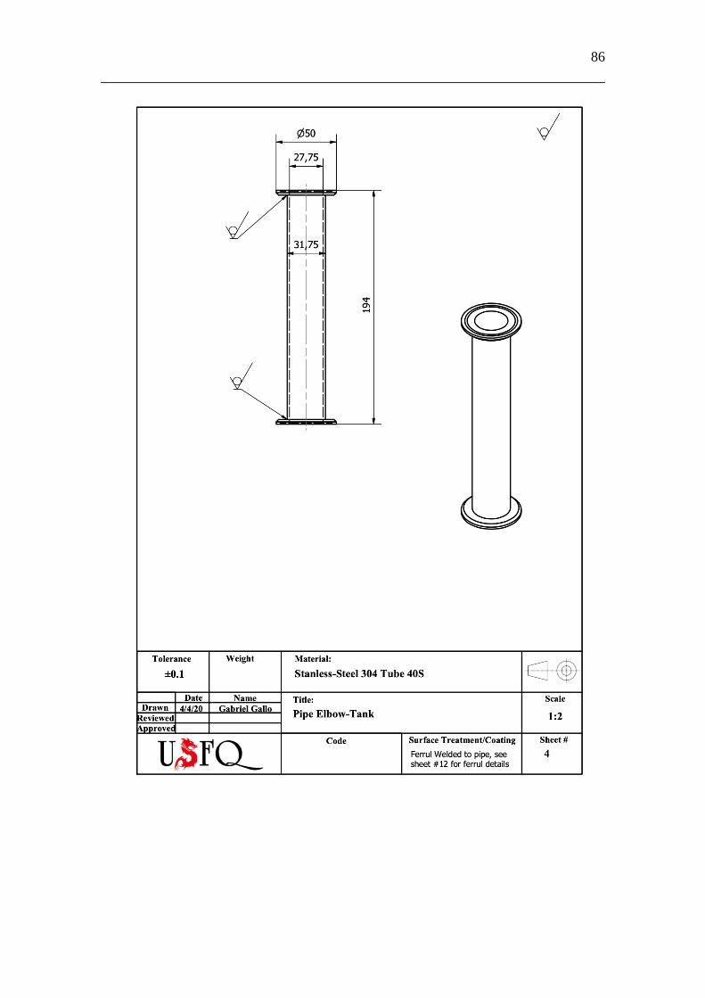
86

87

88

89

90

91

92

93

94
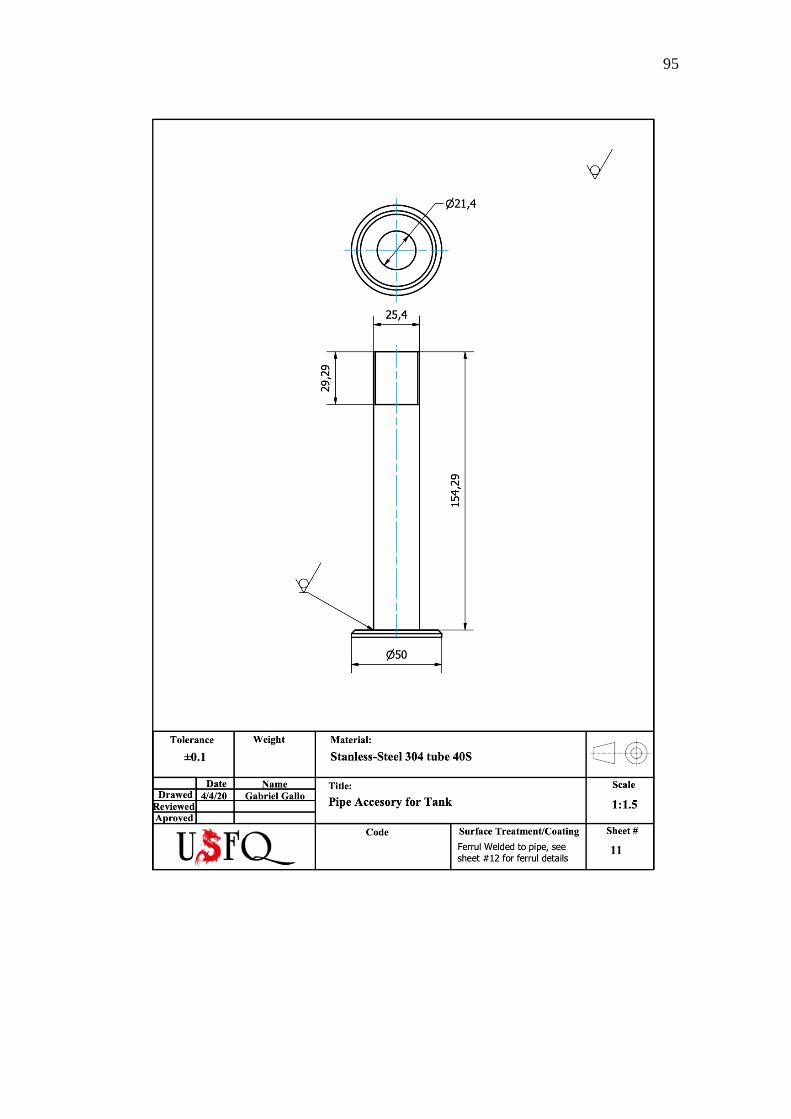
95

96
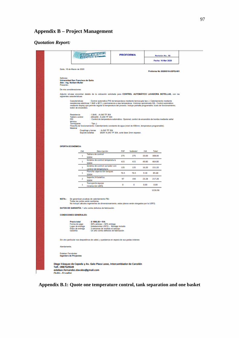
97
Appendix B – Project Management
Quotation Report:
Appendix B.1: Quote one temperature control, tank separation and one basket

98
Appendix B.2: Quotation pipes, ferrules and clamps Part 1

99
Appendix B.3: Quotation pipes, ferrules and clamps Part 2

100
Gaant Chart:
Table # 17: Gaant Chart for manufacturing process

101
Piping System
Table # 18: Piping system part list
Part Quantity Length
[mm]
L
Tolerance[mm]
Width
[mm]
Diameter
[mm]
D
Tolerance
[mm]
Measurement
Instrument
Measurement
Responsible
Pump-Elbow
Pipe
2 97.15 ±1 2.00 15.87 ±0.1 Tape Measure &
Caliper
Martín Dávila &
Gabriel Gallo
Piping Elbow 4 125.70 ±1 2.00 15.87 ±0.1 Tape Measure &
Caliper
Martín Dávila &
Gabriel Gallo
Elbow-Tank
Pipe
2 194.46 ±1 2.00 15.87 ±0.1 Tape Measure &
Caliper
Martín Dávila &
Gabriel Gallo
Tank-Elbow
Pipe
2 80.65 ±1 2.00 15.87 ±0.1 Tape Measure &
Caliper
Martín Dávila &
Gabriel Gallo

102
Tank-Pump
Pipe
2 50.00 ±1 2.00 31,75 ±0.1 Tape Measure &
Caliper
Martín Dávila &
Gabriel Gallo
Vertical
Distribution Pipe
8 50.00 ±1 1.52 25.40 ±0.1 Tape Measure &
Caliper
Martín Dávila &
Gabriel Gallo
Horizontal
Distribution Pipe
2 580.00 ±1 1.52 25.40 ±0.1 Tape Measure &
Caliper
Martín Dávila &
Gabriel Gallo
Nozzle 48 25.00 ±0.5 1.50 5.25 ±0.5 Caliper Martín Dávila &
Gabriel Gallo
Valve 2 - - - 31,75 - Caliper Martín Dávila &
Gabriel Gallo
Grid Basket 2 8920.00 ±1 - 4.00 ±0.1 Tape Measure &
Caliper
Martín Dávila &
Gabriel Gallo
Bottle-Holder
Rack
2 2986.68 ±1 - 7.00 ±0.1 Tape Measure &
Caliper
Martín Dávila &
Gabriel Gallo
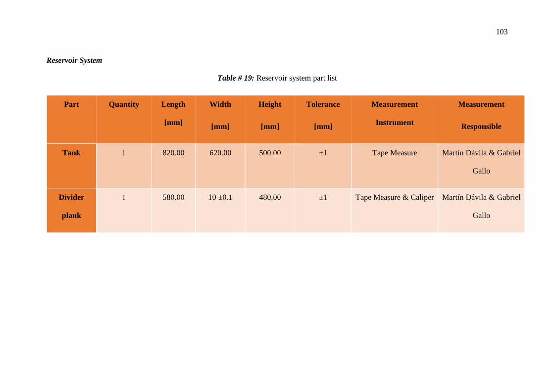
103
Reservoir System
Table # 19: Reservoir system part list
Part Quantity Length
[mm]
Width
[mm]
Height
[mm]
Tolerance
[mm]
Measurement
Instrument
Measurement
Responsible
Tank 1 820.00 620.00 500.00 ±1 Tape Measure Martín Dávila & Gabriel
Gallo
Divider
plank
1 580.00 10 ±0.1 480.00 ±1 Tape Measure & Caliper Martín Dávila & Gabriel
Gallo
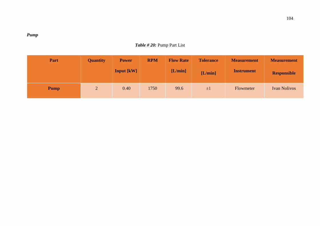
104
Pump
Table # 20: Pump Part List
Part Quantity Power
Input [kW]
RPM Flow Rate
[L/min]
Tolerance
[L/min]
Measurement
Instrument
Measurement
Responsible
Pump 2 0.40 1750 99.6 ±1 Flowmeter Ivan Nolivos

105
Water Heating System
Table # 21: Composed by two parts that contains all the parameters to be measure and controlled by the manufacturers
Stainless Steel Resistance
Parameters to consider Value Tolerance Measurement Instrument Measurement Responsible
Diameter 25.4 mm +/- 0.1 mm Caliper Andi Villacis
Length 250 mm +1% Caliper Andi Villacis
Voltage input (Max) 415 V - Multimeter Andi Villacis
Current Input (Max) 14 A - Multimeter Andi Villacis
Power input (>100W) 6000 W +/- 5-10 % - Andi Villacis
Maximum Temperature 700 C - Pyrometer Andi Villacis
Maximum Pressure 15 Bar - - N/A

106
Pyrometer
Measure Magnitudes Value Tolerance Measurement Instrument Measurement Responsible
Temperature (max) 100-300 C 0,5 % ± 5°C - -
Voltage DC 24 V ± 10 % Multimeter Andi Villacis
Current < 100 mA
Multimeter Andi Villacis
Pump Controller
Table # 22: Pump Controller part list
Part # Name Installation Responsible
1 Display Ivan Nolivos
2 Wires Ivan Nolivos
3 PLC Ivan Nolivos

107
4 Stop Button Ivan Nolivos

108
Manufacturing Diagram
Appendix B.4: Manufacturing Diagram

109
Leak Testing
Table # 23: Leak Test Parameters
Data Description Relevance Parameters applied by the
designers for the testing
Test circuit number Allows the designer to know how
much tests will be taken
When applying experimental methods, it is important that the
results obtained at the tests show a pattern that repeats and
matches with other tests. If the pattern repeats, the system
will have the same behavior during its operation.
10 Iterations by each fluid
Piping Instrumentation and
diagrams
A list that shows an identification of
pipes and also the fittings added to
the pipelines. Also, the hydraulic
planes and the flux diagrams must
be considered.
The hydraulic plane illustrates all the pipes and fittings in the
system. In case of a leaking detection, this part must be
considered in the plane for the designers to make a review of
what happened during the process and effectuate the
appropriate corrections.
Hydraulic Planes, Mechanical
planes, and manufacturing diagram

110
Tests days Shows which day the test has been
taken
The date is important because, in case of failures or good
behavior, designers could archive and interpret pattern along
the time.
April 24, 2020
April 27, 2020
May 1, 2020
Location within facility Shows specific place where the test
will be taken
Location is an important fact to analyze because the results
of the tests could vary according to the place where the tests
are performed. If the location where the test is taken does not
affect to the system, then, the system is developing its tasks
properly.
USFQ workshop
Open field (soccer court)
USFQ Food Plant
Design Pressure The average pressure for which the
machine has been designed
This pressure will allow the designer to know how much the
pressure could variate from its designed values and also for
how much it will increase up to the test
32.39 kPa.g
Test Pressure Pressure which is going to be
applied to the system for testing
This pressure will exceed the standard levels of the designed
values. This is to test if the system can resist to an additional
amount of pressure. Accidents could happen and in case of a
failure, system must support this failure with no leaking or
sealing failures.
50 kPa

111
Test fluid Different fluids considered for
testing
For the bottle washing machine, there are two fluids of
interests, it is important that the system does not fail using
any of these fluids.
Water
NaOH
Test fluid temperature Temperature that will be applied for
fluids
When the bottle Washing machine is working, it flows hot
water over the pipelines, this could produce thermal stresses
producing changes on the results
20 ℃
(5 tests with water and 5 tests with
NaOH)
85 ℃
(5 tests with water)
30 ℃
(5 tests with NaOH)
Time How much time does the test will be
carried out
Time is an important variable to verify how long does the
system supports the elevation of the pressure.
5 tests of 5 minutes
5 tests of 10 minutes
(For each fluid)

112
Differential of pressure Shows how much has the pressure
has been risen or reduced
This allows to know how much pressure has been
incremented from the designed values. 17.61 kPa.g
Comments Comments about the pipelines,
pump, fittings and others
If leaks appear, they must be commented with its intensity.
Also, if the system does not show leaks, a positive
commentary about the well behavior of the system should be
done.
-
Signatures Responsible of the tests must sign During the test, responsible personal will be assigned to
supervise and to operate the system in case of a failure
Ivan Nolivos
Gabriel Gallo
Martin Davila
Andi Villacis

113
Pressure Testing
Table # 24: Pressure Testing Parameters
Data Description Relevance Parameters applied by the
designers for the testing
Test circuit
number
Allows the designer to know
how much tests will be taken
When applying experimental methods, it is important that the results
obtained at the tests show a pattern that repeats and matches with other tests.
If the pattern repeats, the system will have the same behavior during its
operation.
10 Iterations by each fluid
Instrumentation
and diagrams
A list showing the components
that interact in the test such as
pumps. In addition, it should be
considered a pressure plane of
the pumps
It is important these planes since it compares the initial pressure to us and
to be able to compare the experimental data with the theoretical ones
Pressure Planes, Performance
Plane

114
Date of tests Shows which day the test has
been taken
Dates is important for a time comparison to find out if there is a problem
with the system
April 15, 2020.
May 25, 2020
May 1, 2020
Location Shows a specific place the test
was performed
Location helps us know if the test performance varies according to location.
It allows us to analyze and compare whether or not the location affects the
development of the system
-USFQ workshop
-USFQ Food processing plant
Design Pressure The average pressure for which
the machine has been designed
Design pressure helps us get an idea of the result we expect and compare for
further analysis
32.39 kPa.g
Test Pressure Pressure which is going to be
applied to the system for testing
Higher pressure should be tested to verify that the system may have and
observe its effects in the event the system fails. The system can fail and
increase the pressure at the system outlet causing accidents
50 kPa
Test fluid Different fluids considered for
testing
For the bottle washing machine, there are two fluids of interests, it is
important that the system does not fail by using any of these fluids.
Water
NaOH

115
Test fluid
temperature
Temperature to be applied to the
fluid
The temperature can be a factor for changing the pressures and therefore the
results
20 ℃ (5 tests with water and 5
tests with NaOH)
85 ℃ (5 tests with water)
30 ℃ (5 tests with NaOH)
Time How much time does the test
will be carried out The time to observe if there is any variation in height is considered.
5 tests of 5 minutes
5 tests of 10 minutes
(For each fluid)
Differential of
heights
Shows how much has the
heights has been risen or
reduced
The height difference allows to know if there is a reduction or increase in
pressure
5 cm
10cm
Comments
Comments about the results,
heights, variables to take into
account
If the system shows height difference in the jet, it must be notified to analyze
what happens. Also comment if the system works correctly -

116
Signatures Responsible of the tests must
sign
During the test will be always assigned responsible persons to supervise and
to operate the system in case of a failure
Ivan Nolivos, Gabriel Gallo
Martin Davila, Andi Villacis

117
Troubleshooting
Table # 25: Troubleshooting Solutions
Problem Detail Solution
Alignment
Bottle not correctly fastened
When this occurs, operator must verify that the tension cables are correctly fastened to the structure and
verify that there is not any interference between the cables and the set of bottles situated. Always follow the
instructions detailed on the datasheet for the type of bottles designed. If the problem persists, verify if the
cable is joined to the base structure of the rack, if the cable is separated, the operator must contact the
designers to fix the welding failure.
Bottle not compatible with the rack
Operator must respect the shapes of the bottles that are specified on the data sheet. If a different bottle is
used, accidents will occur. If the bottle is not aligned, hot water could spill over people causing second grade
burnings on the skin or damaging objects near. Additional, if the bottle does not fit in its specific place do
not force it, because it could damage the structure.
Bottle-holder rack Fasten the bolts to adjust the tensor cables or verify if the welding points of the structure are still functional.

118
Clamping Piping joints
Always, operator must test the system with cold water at both sides to verify if there is any clamping trouble.
If any of the joints is not well secured, separate the part and join it again by applying an adequate torque
(enough to secure the bolts but not too much to damage the thread). If the clamps are still failing, the
designers must check the system and verify if it is necessary to replace the clamp or effectuate a procedure
of material wear.
Leaking Joints
When the prototype is tested, leaking must be verified. If the system is leaking, try to verify exactly which
points have this problem and disarm up to the failure point. If the system persists, take all the parts out and
assemble the entire system again. If the problem is still present, welding or corrosion problems could be
present on the system, if this is the case, contact with the designers to fix the problem.
Corrosion Corrosion Points
Even if we are working with stainless steel, corrosion will affect at any moment of the life time operation of
the bottle washing machine. Periodical inspections must be effectuated (at least every 3 months) to check if
there is any problem. If the corroded point is not too big, the operator could grind the surface with sandpaper
until this point is disappeared. If this corrosion point growths or if there is any big point of corrosion, the
pipe should be replaced or take out a surface treatment to solve this problem.

119
Cavitation Pump impeller
The system is designed to avoid cavitation but with the pass of the time and depending on the usage of the
machine, cavitation could erode the internal surface of the impeller. Operator must check if the impellers are
not showing erosion problems, if this happens, contact to the designers to effectuate adjustments into the
flow rate of fluid and also at the pressure. This will keep the system functional for a longer period of time.
Erosion Internal surface of pipes
Always keep the tanks clean, verify that there are not solids that comes inside the piping system. When solids
crashes with the walls, they could wear out the system and it could cause leaking problems and orifices on
the pipe in extreme cases. In case of advanced erosion, the pipe must be immediately replaced. The inspection
of the pipe must be taken at least each 3 months.
Water Heating System
Overheating
Too much power input into the resistance could damage it, but before this happens, the relay system must
this by shooting off the water heating system. If the relay jumps, immediately the operator must turn off all
the system by using the emergency stop button. Wait at least 30 minutes until the system colds and test the
system by preheating the water. If the pyrometer shows atypical data, do not use the equipment and contact
with the designers.
Circuit damage If the system is not working, do not force it, do not manipulate it, contact with the designer to replace the
necessary parts and effectuate the necessary corrections

120
Electrical System does not run
If the system is not running, verify the connection of the pump with the pump controller. Verify also if the
system connector to the power source is well connected. If all the connections are verified and the system is
still not running, do not manipulate, contact with the designers to replace the necessary parts and solve the
electrical problems.

121
Design, Concepts and Selections
Water heating
Table # 26: Selection Criterion for water heating
Weight < Operating Safety < Precision = Cost
Requirements and criteria suggested for heating water
CRITERIA Weight Cost Precision Operating
Safety E+1 Weighted
Weight 0 0 0 0 0,00
Cost 1 0,5 0 1,5 0,27
Precision 1 0.5 0 1 0,18
Operating Safety 1 1 1 3 0,55
Total 5,5 1,00

122
Cost
Hybrid < Gain Heater < Resistance Heater
Cost analysis
CRITERIA Resistance
Heater Gain Heater Hybrid E+1 Weighted
Resistance
Heater 1 1 2 0,67
Gain Heater 0 1 1 0,33
Hybrid 0 0 0 0
Total 3 1
Weight
Hybrid < Gain Heater < Resistance Heater
Weight analysis
CRITERIA Resistance
Heater Gain Heater Hybrid E+1 Weighted
Resistance
Heater 1 1 2 0,67
Gain Heater 0 1 1 0,33
Hybrid 0 0 0 0
Total 3 1
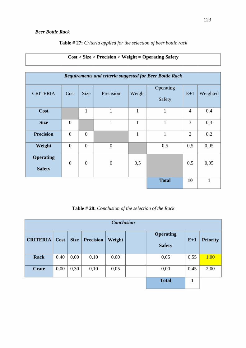
123
Beer Bottle Rack
Table # 27: Criteria applied for the selection of beer bottle rack
Cost > Size > Precision > Weight = Operating Safety
Requirements and criteria suggested for Beer Bottle Rack
CRITERIA Cost Size Precision Weight Operating
Safety E+1 Weighted
Cost 1 1 1 1 4 0,4
Size 0 1 1 1 3 0,3
Precision 0 0 1 1 2 0,2
Weight 0 0 0 0,5 0,5 0,05
Operating
Safety 0 0 0 0,5 0,5 0,05
Total 10 1
Table # 28: Conclusion of the selection of the Rack
Conclusion
CRITERIA Cost Size Precision Weight Operating
Safety E+1 Priority
Rack 0,40 0,00 0,10 0,00 0,05 0,55 1,00
Crate 0,00 0,30 0,10 0,05 0,00 0,45 2,00
Total 1

124
Precision
Hybrid > Gain Heater > Resistance Heater
Operation precision analysis
CRITERIA Resistance
Heater Gain Heater Hybrid E+1 Weighted
Resistance
Heater 0 0 0 0
Gain Heater 1 0 1 0,33
Hybrid 1 1 2 0,67
Total 3 1
Safety
Hybrid = Gain Heater < Resistance Heater
Operation safety analysis
CRITERIA Resistance
Heater Gain Heater Hybrid E+1 Weighted
Resistance
Heater 1 1 2 0,67
Gain Heater 0 0,5 0,5 0,17
Hybrid 0 0,5 0,5 0,17
Total 3 1

125
Conclusion
Conclusion
CRITERIA Weight Cost Precision Operating
Safety E+1 Weighted
Resistance
Heater 0,00 0,18 0,00 0,36 0,55 1
Gain
Heater 0,00 0,09 0,06 0,09 0,24 2
Hybrid 0,00 0,00 0,12 0,09 0,21 3
Pipe Selection
Table # 29: Criteria applied for the selection of the piping system
Table # 30: Conclusion of the piping system selection

126
Engineering Analysis
Milestone #1: Bottle-holder rack design
Problem: The structural basket has 24 cavities for holding different size glass bottles for
their washing process. The basket holds the beer bottle by their upper part, since there are
placed upside down. The bottom of the bottle is hold by another adjustable bar in the top
of the basket, this way the bottle is secured for the washing process. It is necessary to
analyze if the basket design is the appropriate for the process, since it must support the
loads and the stresses produced by them on and off the procedure.
Figure # 36: Bottle holder basket
For the analysis the lower bars, which support the bottle weight during the process,
will be analyzed for the most critical situations. This scenario will be when the entire
bottle is supported by only one of the bars -the bottle normally should be supported in 4
points, two in the bars located lengthwise and two located breadthways the basket. The
bar located lengthwise is the one chosen for the analysis due to it is longer and holds more

127
bottles tan the one located breadthways. Also, the spaces where the upper part of the bottle
is located are more spaced in lengthwise than Breadthways.
Figure # 37: Final Assembly
Also, the analysis will be done at the moment the basket is in more stress and this
is when the system is off, but the basket is charged with bottles. This is because when the
system is on the water or caustic soda jet pumped into the bottle will relieve, in a small
scale, the weight of the bottle from their supporting points.
Known:
Material: Stainless Steel AISI 304
𝑭𝑭𝒀𝒀 = 205 [𝑀𝑀𝑀𝑀𝑀𝑀]
𝒓𝒓 = 3,5 [𝑚𝑚𝑚𝑚] (still bar radius)

128
𝒘𝒘𝒃𝒃𝒃𝒃𝒃𝒃𝒃𝒃𝒃𝒃𝒃𝒃 = 𝑤𝑤𝑏𝑏 = 83 [𝑁𝑁]
Procedure:
Simplified System:
Figure # 38: Simplified structural system
Free body Diagram:
Figure # 39: Simplified structural system’s free body diagram
Since there are no forces in the x-axis direction:
𝑹𝑹𝑨𝑨,𝒙𝒙 = 𝑹𝑹𝑩𝑩,𝒙𝒙 = 0 [𝑁𝑁]
Due to symmetry:
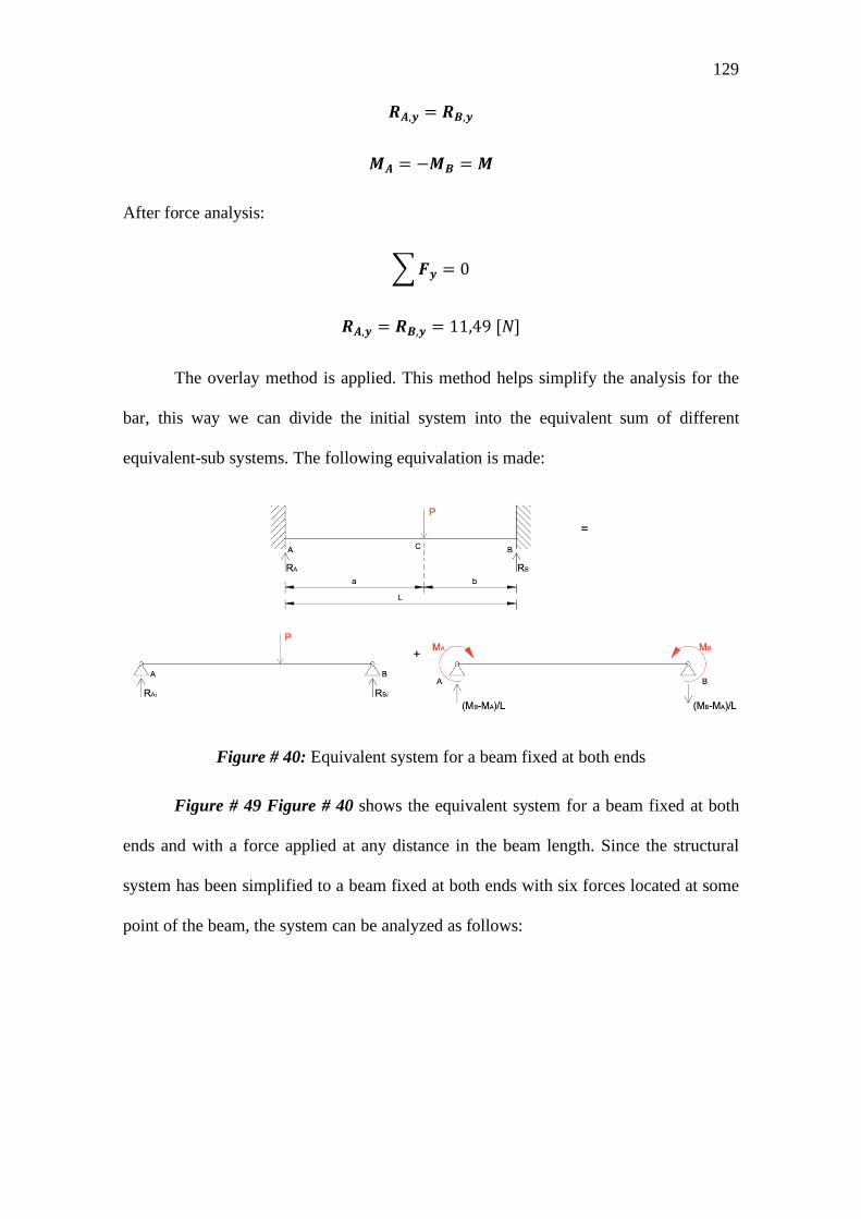
129
𝑹𝑹𝑨𝑨,𝒚𝒚 = 𝑹𝑹𝑩𝑩,𝒚𝒚
𝑴𝑴𝑨𝑨 = −𝑴𝑴𝑩𝑩 = 𝑴𝑴
After force analysis:
�𝑭𝑭𝒚𝒚 = 0
𝑹𝑹𝑨𝑨,𝒚𝒚 = 𝑹𝑹𝑩𝑩,𝒚𝒚 = 11,49 [𝑁𝑁]
The overlay method is applied. This method helps simplify the analysis for the
bar, this way we can divide the initial system into the equivalent sum of different
equivalent-sub systems. The following equivalation is made:
Figure # 40: Equivalent system for a beam fixed at both ends
Figure # 49 Figure # 40 shows the equivalent system for a beam fixed at both
ends and with a force applied at any distance in the beam length. Since the structural
system has been simplified to a beam fixed at both ends with six forces located at some
point of the beam, the system can be analyzed as follows:

130
Figure # 41: Decomposition into sub-systems for the analyzed beam
Each of these systems has a same magnitude force “Wb” applied at a different distance “a” distance from the end “A” and a “b” distance
of the end “B”. As the Figure # 41 shows a sum of 7 sub-systems, six simple supported beam systems with one force applied and a simple supported
beam with momentum at both ends, are needed emulate the original beam to be analyzed. The first 6 systems are very similar to each other and
they only differ by the distances “a” and “b” where the load is applied

131
For all the systems:
𝑳𝑳 = 570 × 10−3 [𝑚𝑚]
𝑷𝑷 = 𝑤𝑤𝑏𝑏 = 3,83 [𝑁𝑁]
For case [1]
a= 53,25 × 10⁻³ [𝑚𝑚]
b= 516,75 × 10⁻³ [𝑚𝑚]
For case [2]
a= 145,95 × 10⁻³ [𝑚𝑚]
b= 424,05 × 10⁻³ [𝑚𝑚]
For case [3]
a= 238,65 × 10⁻³ [𝑚𝑚]
b= 331,35 × 10⁻³ [𝑚𝑚]
For case [4]
a= 331,35 × 10⁻³ [𝑚𝑚]
b= 238,65 × 10⁻³ [𝑚𝑚]
For case [5]
a= 424,05 × 10⁻³ [𝑚𝑚]
b= 145,95 × 10⁻³ [𝑚𝑚]
For case [6]

132
a= 516,75 × 10⁻³ [𝑚𝑚]
b= 53,25 × 10⁻³ [𝑚𝑚]
The literature gives, for each sub system the specific formula for the momentum at
“A” and “B”, as it follows:
𝑴𝑴𝑨𝑨 =−𝑀𝑀𝑀𝑀𝑎𝑎2
𝐿𝐿2
𝑴𝑴𝑩𝑩 =−𝑀𝑀𝑀𝑀2𝑎𝑎𝐿𝐿2
Since the momentum at A and B will be the same due symmetry “MA” is picked to
be calculated. Making the respective calculation, each momentum is gotten as it follows:
Case [1]:
𝑴𝑴𝑨𝑨,𝟏𝟏 = −0,168 [𝑁𝑁.𝑚𝑚]
Case [2]:
𝑴𝑴𝟐𝟐,𝟐𝟐 = −0,309 [𝑁𝑁.𝑚𝑚]
Case [3]:
𝑴𝑴𝟐𝟐,𝟑𝟑 = −0,309 [𝑁𝑁.𝑚𝑚]
Case [4]:
𝑴𝑴𝟐𝟐,𝟒𝟒 = −0,222 [𝑁𝑁.𝑚𝑚]
Case [5]:
𝑴𝑴𝟐𝟐,𝟒𝟒 = −0,106 [𝑁𝑁.𝑚𝑚]
Case [6]:

133
𝑴𝑴𝟐𝟐,𝟒𝟒 = −0,017 [𝑁𝑁.𝑚𝑚]

134
This way, using the first equality relation we have that:
𝑴𝑴𝑨𝑨 = 𝑴𝑴𝑩𝑩 = 𝑴𝑴 = 𝑴𝑴𝟐𝟐,𝟏𝟏 + 𝑀𝑀2,2 + 𝑀𝑀2,3 + 𝑀𝑀2,4 = −1,131 [𝑁𝑁.𝑚𝑚]
|𝑴𝑴| = 1,131 [𝑁𝑁.𝑚𝑚]
Having the value of the momentum at the fixed points it’s possible to calculate the
stress at this point points using the following equation:
𝝈𝝈 =|𝑴𝑴|𝑺𝑺
Where S is the section modulus. Since the section modulus for a bar is a circulus:
𝑺𝑺 =𝜋𝜋𝑟𝑟3
4
𝑺𝑺 = 3,37 × 10⁻⁸[𝑚𝑚]
∴ 𝝈𝝈𝒎𝒎 = 33,59 [𝑀𝑀𝑀𝑀𝑀𝑀]
Now with both, the maximum stress in the bar and the yield strength of the material,
it is possible to calculate the safety factor for the design system:
𝜼𝜼 =𝐹𝐹𝑦𝑦𝜎𝜎𝑚𝑚
𝜼𝜼 = 6,1
Since the most critical element in the structural system was analyzed and since the
safety factor found in the analysis is bigger than 6; it is possible to observe that the structural
element is not a critical one in the entire system design. In fact, for this design is possible to
reduce de geometry dimensions of the bars and it would still be a reliable design, reducing
weight and costs, both very important parameters discussed before in the report.
135
Milestone #2: Water Heating
Problem: For Designing a Bottle Washing, it must heat the water contained in the thank
considering that at the beginning, the water will be between 15 °C – 18 °C (Hint: consider
an average temperature of 16.5 °C). However, that water should be heated up to 90 °C before
start recirculating. Once it recirculates along the piping, you have to ensure that after getting
out of the nozzle, water should be at least at 75 °C in order to follow Sanitizing Standards.
With this in mind, consider that water heating will be made by a commercial electrical
resistance and provide a calculation for heat transferred on the system.
Known:
𝑻𝑻𝑭𝑭𝑾𝑾𝑾𝑾𝒃𝒃𝒃𝒃𝒓𝒓 = 90 °C
𝑪𝑪𝑷𝑷𝑾𝑾𝑾𝑾𝒃𝒃𝒃𝒃𝒓𝒓 = 4.186 kJ
𝑘𝑘𝑘𝑘 𝐾𝐾 (@ 𝟏𝟏 𝑾𝑾𝒃𝒃𝒎𝒎)
∀𝒘𝒘𝑾𝑾𝒃𝒃𝒃𝒃𝒓𝒓= 83.52 𝐿𝐿 (𝑾𝑾𝒂𝒂𝒂𝒂𝒂𝒂𝒎𝒎𝒂𝒂𝒂𝒂𝒂𝒂 𝒉𝒉𝒃𝒃𝒂𝒂𝒂𝒂𝒉𝒉𝒃𝒃 𝒃𝒃𝒐𝒐 𝟒𝟒𝟒𝟒 𝒄𝒄𝒎𝒎)
𝒃𝒃𝒑𝒑𝒓𝒓𝒃𝒃𝒉𝒉𝒃𝒃𝑾𝑾𝒃𝒃𝒂𝒂𝒂𝒂𝒂𝒂 = 40 𝑚𝑚𝑚𝑚𝑚𝑚
𝝆𝝆𝒘𝒘𝑾𝑾𝒃𝒃𝒃𝒃𝒓𝒓 = 998.84 𝑘𝑘𝑘𝑘𝑚𝑚3
Assumptions:
𝑻𝑻𝟒𝟒𝑾𝑾𝑾𝑾𝒃𝒃𝒃𝒃𝒓𝒓 = 15 °C − 18 °C (𝐀𝐀𝐀𝐀𝐀𝐀:𝟏𝟏𝟏𝟏.𝟓𝟓 °𝐂𝐂 )
𝑷𝑷𝒓𝒓𝒃𝒃𝒂𝒂𝒂𝒂𝒂𝒂𝒓𝒓𝒃𝒃 = 1 𝑀𝑀𝑎𝑎𝑚𝑚
Constant Properties

136
Heat needed for Preheating:
Heat needed for preheating water from 16.5 °C to 90 °C, can be estimated by using this
equation:
𝑸𝑸 = 𝑚𝑚� 𝐶𝐶𝑝𝑝� (∆𝑇𝑇)
𝝆𝝆 =𝑚𝑚
∀𝒘𝒘𝑾𝑾𝒃𝒃𝒃𝒃𝒓𝒓
𝒎𝒎 = 𝝆𝝆 (∀𝒘𝒘𝑾𝑾𝒃𝒃𝒃𝒃𝒓𝒓)
𝑸𝑸 = 𝝆𝝆 (∀𝒘𝒘𝑾𝑾𝒃𝒃𝒃𝒃𝒓𝒓)� 𝐶𝐶𝑝𝑝� (∆𝑇𝑇)
𝑸𝑸 = (998.84) 𝑘𝑘𝑘𝑘𝑚𝑚3 (0.0835)𝑚𝑚3 (4.186)
𝑘𝑘𝑘𝑘𝑘𝑘𝑘𝑘 °𝐶𝐶
(90− 16.5)°𝐶𝐶
𝑸𝑸 = (25666.87) 𝑘𝑘𝑘𝑘
Power needed for Preheating:
Power needed for preheating water from 16.5 °C to 90 °C, can be estimated by using this equation:
�̇�𝑸 =𝑄𝑄𝑎𝑎
�̇�𝑸 =(25666.87)𝑘𝑘𝑘𝑘
(3600) 𝑠𝑠
�̇�𝑸 = (7.13)𝑘𝑘𝑘𝑘

137
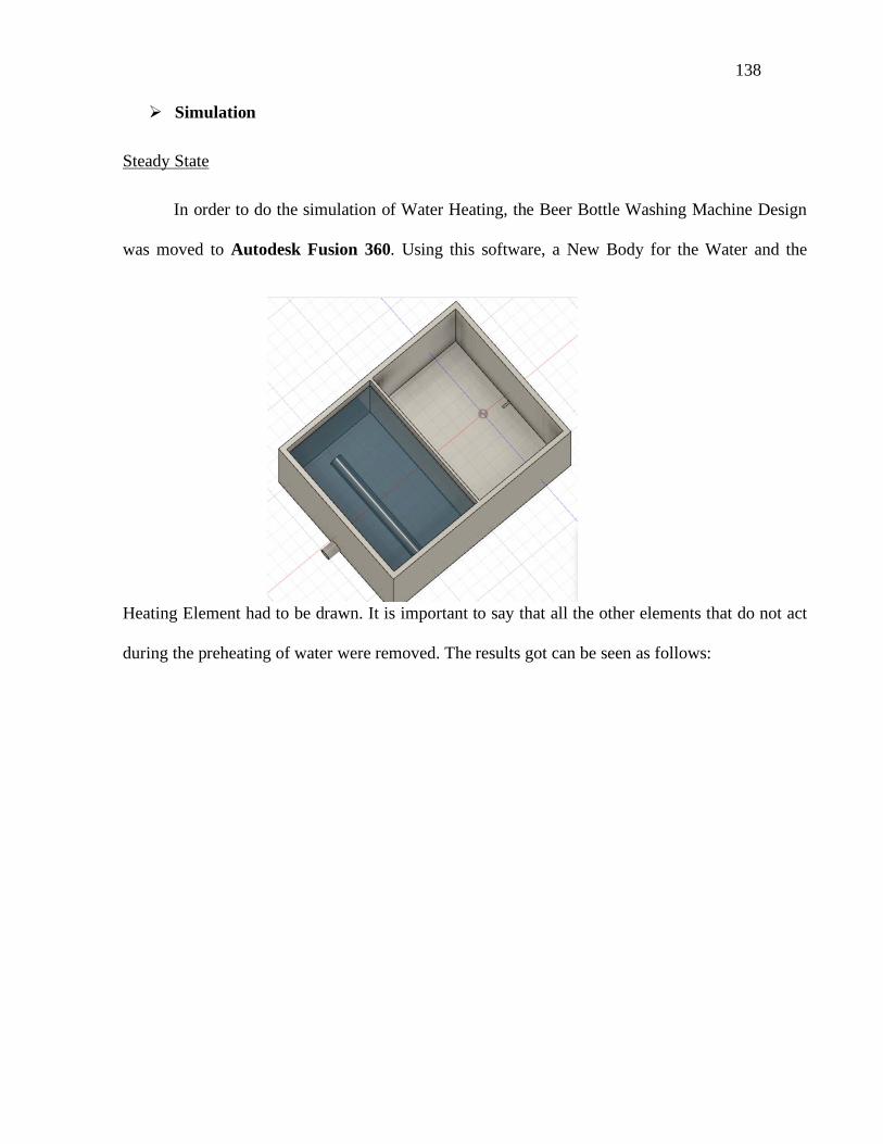
138
Simulation
Steady State
In order to do the simulation of Water Heating, the Beer Bottle Washing Machine Design
was moved to Autodesk Fusion 360. Using this software, a New Body for the Water and the
Heating Element had to be drawn. It is important to say that all the other elements that do not act
during the preheating of water were removed. The results got can be seen as follows:

139
Figure # 42: Water body drawn for simulation Analysis
The Heating Element was simulated as a Cylinder with a Diameter of 2.54 cm and a
Height of 25 cm. This because the Stainless-Steel Resistance found in the Ecuadorian Market
has this specifications. However, it is J Shaped and it is formed by some other small tubes,
but it is a good approximation if a cylinder is used. Specially because the Heat input will be
the same independent of how the heating element is shaped.

140
Figure # 43: Heating Element Drawn for Simulation Analysis
The Material Properties used for all the elements used during Simulation were chosen from
Autodesk Fusion 360 Library, as follows:
Water Thank: Stainless Steel
Figure # 44: Stainless Steel Properties used during Simulation
Water:

141
Figure # 45: Water Properties used during Simulation
For simulating the Water Heating, there were some inputs entered, as follows:
Figure # 46: Water Tank (Top View) was supposed to be at Room Temperature

142
Figure # 47: Water Tank (Isometric View) was supposed to be at Room Temperature
Figure # 48: Water was supposed to be at an average Temperature of 16.5 C

143
Figure # 49: The Heating Element was supposed to give 12 kW to the System
The mesh was automatically generated by the System as can be seen in the following
picture:
Applying previous Inputs, the results got for Steady State are as follow
Figure # 50: Mesh generated by the Software

144
If the Inputs for the water are changed, in order to simulate convection of water with
standard properties, the following results are got: Figure # 51: Results got from Simulation

145
Figure # 52: Results got after using convection of water

146
As it can be seen in the results got during the simulation of the Water Heating, the
water is not heated enough even using a 12 kW Stainless Resistance, as it was supposed from
the previous analyzes. This is why, a coil induction system was suggested in the DESIGN
FOR MANUFACTURING Section.
Transient State
When trying to do the simulation for Transient State, ANSYS FLUENT was used
with the same conditions described before. After running the simulation Considering a
Single-Phase case, there was an error after 52 Seconds. This error was caused because the
water film near the Heating Element evaporates as soon as the Resistance starts to put some
power in the system. So, as the simulation considered a single-phase system because that was
the only one learned during class, the error was caused and results cannot got.

147
Heat Loss during Water Recirculation
For determining the Heat Loss during Water Recirculation, a simulation using
ANSYS FLUENT was performed. For this, it was necessary to Create a watertight Geometry
from the 3D model of the Beer Bottle Washing Machine.
Figure # 53: Error caused due to the consideration of Single Phase Simulation.
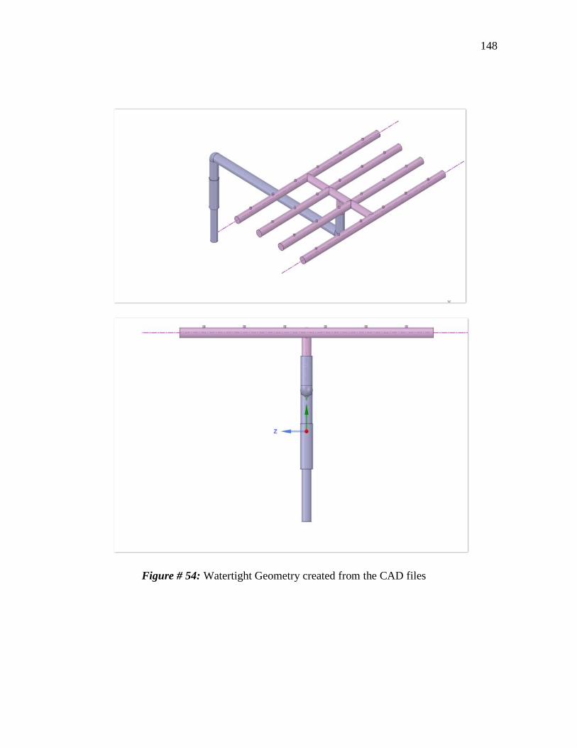
148
Figure # 54: Watertight Geometry created from the CAD files

149
The Stainless-Steel Material Properties used during the simulation of the water tank
were also used for the Simulation of the Piping System as it will be made from Stainless
Steel. These Properties are as follows:
Piping System: Stainless Steel
Figure # 55: Stainless Steel Properties used during Simulation of the Water Distributor
System
The properties of the water used during the simulation of the Piping System were the same as the
ones presented in Figure # 46. The Boundary Conditions used for this simulation were taken from
the results got in the Section .

150
Milestone #4: Pressure drops and losses inside the pipe. These conditions are described
as follows:
Inlet Flow from the pump = 151.04 [L/min]
Flow velocity at Inlet = 27.24 [m/s]
Heat Transfer to the surroundings from the steel pipes = 25 [W/m2K]
Average Temperature in the Surroundings= 295.65 [K]
Average Pressure in the Surroundings = 0.715 [atm]
The Properties for the Fluid used for this simulation were taken from Chemical Engineering
Essentials (Huitt, 2008) and they are described as follows:
Density of the Water = 1031.07 [kg/m3]
Viscosity of the water = 0.97804 [mPas]
Specific Heat was chosen as a constant = 4182 [kJ/kgK]
Surface Roughness of Wall = 0.001211

151
A mesh was generated for the Watertight Geometry presented in Figure # 43. The
following statistics was obtained:
As it can be seen on Figure # 45, the statistics of the Watertight are converging fast
when generating the mesh. This is a good signal when starting to for the simulation because
it means that there are no problems with the Geometry
The final Mesh obtained was as follows:
Figure # 56: Statistics of the Watertight Mesh

152
As it can be seen on Figure # 46, the mesh generated for the Watertight is a
combination of triangles and hexagons distributed in the most efficient way possible.
Figure # 57: Final Mesh Obtained

153
After running the simulation with the conditions described before, the following
results were got:
Residuals after 1100 Iterations are shown below:
Figure # 58: Residuals after 1100 Iterations
As it can be seen on Figure # 59, the mesh generated for the residuals start to
converge after 1100 iterations, which means that the software is finding a solution for the
specific conditions of the problem.
The Average Temperature at the Outlet is shown below:
Figure # 59: Average Temperature at the Outlet

154
As it can be seen on Figure # 48, the Temperature at the Outlet doesn’t change after
400 Iterations, which means that the problem was solved very fast.
As it can be seen on Figure # 49, the Temperature of the Fluid is almost the same
through the Piping system. This because of the specific conditions of the problem.
Furthermore, the specific heat of the water and the high Heat transfer coefficient of the
Stainless Steel make this possible
Figure # 60: Path lines of Static Temperature through the Piping System

155
As it can be seen on Figure # 50Figure # 49, the Temperature of the Fluid is almost
the same through the Water Distributor System. The temperature experiments a little decrease
near the nozzle because in this part there are atmospheric conditions and a Temperature
Variation. However, this difference is not that high and lets the fluids to stand at the desired
temperature.
Figure # 61: Contours of Static Temperature through the Water Distributor System

156
As it can be seen on Figure # 51Figure # 50Figure # 49, the Temperature of the
Fluid is almost the same through the Water Distributor System even tough that this fluid is
running at high velocity and high pressure.
Figure # 62: Pathlines of Static Temperature through the Water Distributor System

157
As it can be seen on Figure # 52Figure # 50Figure # 49, the Temperature of the fluid
at the outlet is uniformly except for the part near the exit. This because that spot is formed
mostly by air due to the high velocity of the water at reaching the nozzle.
The Average Flow Rate at the Outlet is shown below:
Figure # 63: Average Temperature at the Outlet

158
As it can be seen on Figure # 53, the Average Flow Rate at the Outlet doesn’t change
after 50 Iterations, which means that the problem was solved very fast.
Figure # 64: Average Flow Rate at the nozzle

159
Figure # 65: Contours of Static Velocity through the Piping System
As it can be seen on Figure # 66Figure # 49, the Velocity of the Fluid is very high at
the inlet because it is pumped up with high pressure. Then, the Fluid reaches the first elbow
with lower velocity due to the losses caused by Potential Energy. After that, the fluid reaches
the Water Distributor System with a lower velocity and the is pumped at the outlet. The Even
though there are a lot of losses through the system, the outlet velocity of the fluid is very
high. The Velocity Vectors can be seen at Figure # 55, where it is possible to appreciate how
fast the fluid is moving through the system. For this reason, some vortices are created on the
spots were the fluid changes its direction.

160
Figure # 66: Velocity Vectors through the Piping System Figure # 67: Contours of Static Velocity through the Water Distributor System

161
As it can be seen on Figure # 56, the Velocity of the Fluid is almost the same through
the Water Distributor System. This because the fluid flows smoothly is this part after
experimenting the majority of the losses through the piping system. However, this velocity
increases at the nozzle due to the change of the diameter. The Velocity Vectors through the
Water Distributor System can be seen at Figure # 57, where it is possible to appreciate how
the fluid is moving through this system. There are some vortices were the fluid changes its
direction and that is because of the high velocity at which the fluid is moving.
Figure # 68: Velocity Vectors through the Water Distributor System

162
As it can be seen on Figure # 58Figure # 50Figure # 49, the Velocity of the fluid at
the outlet is uniformly except for the part near the exit. This because that spot is formed
mostly by air due to the high velocity of the water at reaching the nozzle.
From the results shown before, the following conclusions were obtained:
Average Velocity at outlet = (15) m/s
Height to which the Water is pumped out through nozzles = (11.47) m
Average Temperature at outlet = (347) K
These results are accurate because the Pump has a lot of power, so the Water is
pumped out the nozzle with high velocity and pressure. Furthermore, the specific heat of the
water is very high, so, there is not a big difference temperature between inlet and outlet.
Milestone #3: Automation
Problem: The Heating Element will remain on for a long time, how can energy be saved if it
is known that the customer wishes to maintain the water temperature in a certain range?
Figure # 69: Velocity Contours at the Nozzle

163
Temperature Control
A conditioning circuit was considered for temperature control. This circuit works
through signals, if 0.5 V is sent our machine will be turned off, but if we send more than one
volt our machine will turn on. “The signal conditioner is a data collector that converts
mechanical or electrical signals into another output signal. “Amplifies the signal and converts
it into another easy-to-read format that is compatible with data acquisition or machine control
purposes.” (HBM, s/f). The signal conditioner is responsible for signal conversion,
linearization, amplification, filtering, evaluation, various interfaces (Figure # 71)
Figure # 70: Conditioning circuit model. Reprinted form Electronic Instrumentation.
Miguel A. Perez and others, Ed. Thomson-Paraninfo
This system will allow us to control the temperature range in which the induction
heater works and thus save energy in the bottle rinse. If the water is in the allowed hot range,
it will turn off; if it is below the range, it will turn on.
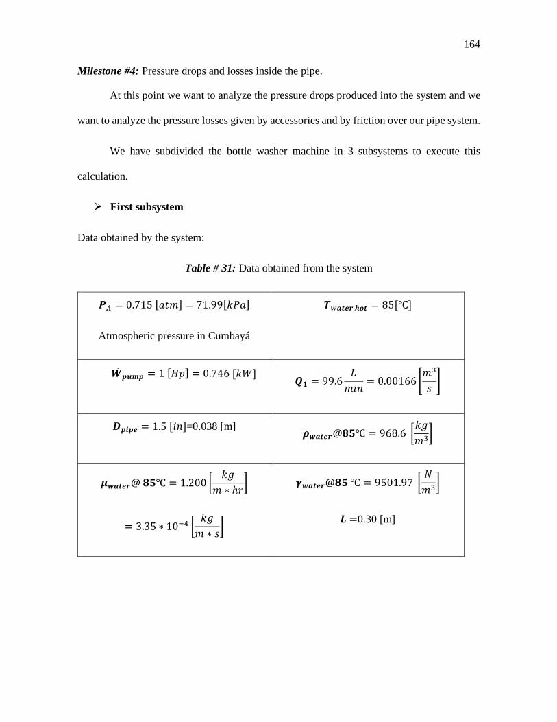
164
Milestone #4: Pressure drops and losses inside the pipe.
At this point we want to analyze the pressure drops produced into the system and we
want to analyze the pressure losses given by accessories and by friction over our pipe system.
We have subdivided the bottle washer machine in 3 subsystems to execute this
calculation.
First subsystem
Data obtained by the system:
Table # 31: Data obtained from the system
𝑷𝑷𝑨𝑨 = 0.715 [𝑀𝑀𝑎𝑎𝑚𝑚] = 71.99[𝑘𝑘𝑀𝑀𝑀𝑀]
Atmospheric pressure in Cumbayá
𝑻𝑻𝒘𝒘𝑾𝑾𝒃𝒃𝒃𝒃𝒓𝒓,𝒉𝒉𝒃𝒃𝒃𝒃 = 85[℃]
𝑾𝑾𝒑𝒑𝒂𝒂𝒎𝒎𝒑𝒑̇ = 1 [𝐻𝐻𝐻𝐻] = 0.746 [𝑘𝑘𝑘𝑘] 𝑸𝑸𝟏𝟏 = 99.6
𝐿𝐿𝑚𝑚𝑚𝑚𝑚𝑚 = 0.00166 �
𝑚𝑚3
𝑠𝑠�
𝑫𝑫𝒑𝒑𝒂𝒂𝒑𝒑𝒃𝒃 = 1.5 [𝑚𝑚𝑚𝑚]=0.038 [m] 𝝆𝝆𝒘𝒘𝑾𝑾𝒃𝒃𝒃𝒃𝒓𝒓@𝟖𝟖𝟓𝟓℃ = 968.6 �𝑘𝑘𝑘𝑘𝑚𝑚3�
𝝁𝝁𝒘𝒘𝑾𝑾𝒃𝒃𝒃𝒃𝒓𝒓@ 𝟖𝟖𝟓𝟓℃ = 1.200 �𝑘𝑘𝑘𝑘
𝑚𝑚 ∗ ℎ𝑟𝑟�
= 3.35 ∗ 10−4 �𝑘𝑘𝑘𝑘𝑚𝑚 ∗ 𝑠𝑠�
𝜸𝜸𝒘𝒘𝑾𝑾𝒃𝒃𝒃𝒃𝒓𝒓@𝟖𝟖𝟓𝟓 ℃ = 9501.97 �𝑁𝑁𝑚𝑚3�
𝑳𝑳 =0.30 [m]

165
At Figure # 72 it is illustrated the problem that is going to be analyzed. The first
analysis is executed from point A to point B. The Point A is at 30 cm of height from B and
30 cm of horizontal length from B.
Figure # 71: First subsystem considered to solve the problem
Equations:
First analysis by Bernoulli is considered to obtain the pressure drop between A and B.
𝑷𝑷𝑨𝑨𝜸𝜸𝒘𝒘
+ 𝒗𝒗𝑨𝑨𝟐𝟐
𝟐𝟐∗𝒂𝒂+ 𝒛𝒛𝑨𝑨 = 𝑷𝑷𝑩𝑩
𝜸𝜸𝒘𝒘+ 𝒗𝒗𝑩𝑩
𝟐𝟐
𝟐𝟐∗𝒂𝒂+ 𝒛𝒛𝑩𝑩 + 𝑯𝑯𝒃𝒃𝒃𝒃𝒂𝒂𝒃𝒃 (1)
Where the lost considered are by friction, by the valve and also for the entrance of the
tank.
To obtain the constant of the minor losses of the valve and the entrance, consider
Figure # 61 and Figure # 74
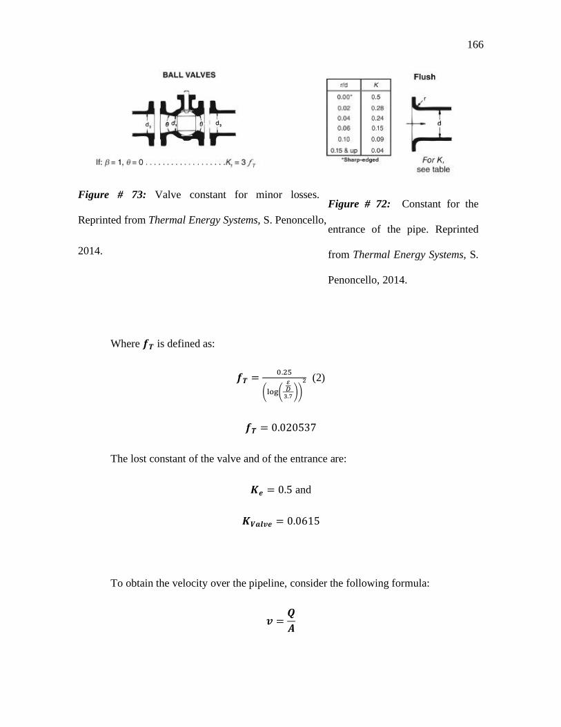
166
Figure # 73: Valve constant for minor losses.
Reprinted from Thermal Energy Systems, S. Penoncello,
2014.
Where 𝒐𝒐𝑻𝑻 is defined as:
𝒐𝒐𝑻𝑻 = 0.25
�log�𝜀𝜀𝐷𝐷3.7��
2 (2)
𝒐𝒐𝑻𝑻 = 0.020537
The lost constant of the valve and of the entrance are:
𝑲𝑲𝒃𝒃 = 0.5 and
𝑲𝑲𝑽𝑽𝑾𝑾𝒃𝒃𝒗𝒗𝒃𝒃 = 0.0615
To obtain the velocity over the pipeline, consider the following formula:
𝒗𝒗 =𝑸𝑸𝑨𝑨
Figure # 72: Constant for the
entrance of the pipe. Reprinted
from Thermal Energy Systems, S.
Penoncello, 2014.

167
Considering the area as:
𝝅𝝅𝟒𝟒 ∗ 𝑫𝑫
𝟐𝟐
So velocity is obtained:
𝒗𝒗 = 1.464𝑚𝑚𝑠𝑠
The formula for the losses is as follows:
𝑯𝑯𝒃𝒃𝒃𝒃𝒂𝒂𝒃𝒃 = �𝒐𝒐 ∗ 𝑳𝑳𝑫𝑫
+ ∑𝑲𝑲� ∗ 𝒗𝒗𝟐𝟐
𝟐𝟐∗𝒂𝒂 (3)
The constant 𝑓𝑓 is defined as the moody constant and obtained with the moody chart
illustrated at Figure # 75. To obtain this constant is necessary to obtain Reynolds number
and the relative roughness.
Reynolds Number
𝑹𝑹𝒃𝒃 =𝝆𝝆 ∗ 𝒗𝒗 ∗ 𝒂𝒂
𝝁𝝁 = 𝟒𝟒.𝟏𝟏𝟒𝟒𝟏𝟏 ∗ 𝟏𝟏𝟒𝟒𝟕𝟕
Relative roughness
𝑹𝑹𝑹𝑹 =𝜺𝜺𝑫𝑫
Where epsilon 𝜺𝜺 is obtained from the Figure # 76.

168
Figure # 74: Moody Chart. Reprinted from: Fundamental of Fluid Mechanics. Munson, B.,
Young, D., & Okiishi, 2017.
Figure # 75: Roughness defined for different materials. Reprinted from Thermal Energy
Systems, S. Penoncello, 2014.

169
Having a relative roughness of:
𝑹𝑹𝑹𝑹 = 0.001211
And taking in consideration the Figure # 75, he following value of 𝒐𝒐 was obtained:
𝒐𝒐 =0.02059
Thus, the losses are obtained
𝑯𝑯𝒃𝒃𝒃𝒃𝒂𝒂𝒃𝒃 = 𝟒𝟒.𝟒𝟒𝟖𝟖𝟖𝟖𝟎𝟎𝟕𝟕 [𝒎𝒎]
Then, the pressure at point B results:
72.95 [kPa]
Second Subsystem
Figure # 76: Illustration of subsystem 2.

170
Here, the same flow rate will be assumed, given the fact that the losses by friction and
by accessories are minimum. So, we obtain: 𝑸𝑸𝟐𝟐 = 𝑸𝑸𝟏𝟏
What is desired to obtain at this subsystem is the head given by the pump to the
system, for then obtaining the pressure at the point C and also the velocity that is going to be
the entrance velocity to the subsystem number 3.
Based on the data considered at Table # 31 the following equations allow us to
compute the results:
𝑯𝑯𝒑𝒑 = 𝑾𝑾𝒑𝒑𝒂𝒂𝒎𝒎𝒑𝒑̇𝜸𝜸𝒘𝒘𝑾𝑾𝒃𝒃𝒃𝒃𝒓𝒓 ∗ 𝑸𝑸𝟐𝟐
= 47.35 [𝑚𝑚]
The Pressure at point C could be obtained. With this, enough information is gotten to
have the velocity at point C.
Considering Bernoulli between points B and C, the following equations are
obtained”:
𝑷𝑷𝑩𝑩𝜸𝜸𝒘𝒘
+𝒗𝒗𝑩𝑩𝟐𝟐
𝟐𝟐 ∗ 𝒂𝒂 + 𝒛𝒛𝑩𝑩 + 𝑯𝑯𝒑𝒑 =𝑷𝑷𝑪𝑪𝜸𝜸𝒘𝒘
+𝒗𝒗𝑪𝑪𝟐𝟐
𝟐𝟐 ∗ 𝒂𝒂 + 𝒛𝒛𝑪𝑪 + 𝑯𝑯𝒃𝒃𝒃𝒃𝒂𝒂𝒃𝒃
Considering Point B as reference, then:
𝒛𝒛𝑩𝑩 = 𝟒𝟒
Also, the velocity inside of the pipes is going to be the same at each point given that
the pump gives to the system a big head and the losses compared to the height gains are
minimum. So, the expression reduces to:
𝑷𝑷𝑩𝑩𝜸𝜸𝒘𝒘
+ 𝑯𝑯𝒑𝒑 =𝑷𝑷𝑪𝑪𝜸𝜸𝒘𝒘
+ 𝒛𝒛𝑪𝑪 + 𝑯𝑯𝒃𝒃𝒃𝒃𝒂𝒂𝒃𝒃

171
The height, where point C is located is:
𝒛𝒛𝑪𝑪 = 𝟒𝟒.𝟑𝟑𝟎𝟎𝟏𝟏 [𝒎𝒎]
The losses formula is the same considered at subsystem 1.
𝑯𝑯𝒃𝒃𝒃𝒃𝒂𝒂𝒃𝒃 = �𝒐𝒐 ∗𝑳𝑳𝑫𝑫 + �𝑲𝑲� ∗
𝒗𝒗𝟐𝟐
𝟐𝟐 ∗ 𝒂𝒂
For the minor losses, this time, 2 elbows are considered, and for major losses consider
a length of:
𝑳𝑳𝟐𝟐 = 𝟒𝟒.𝟎𝟎𝟓𝟓𝟏𝟏 [𝒎𝒎]
The friction factor, 𝒐𝒐 value is going to be the same considered in subsystem 1 because
Reynolds number is the same given that the velocity of the fluid inside the pipe was assumed
to be the same in this part, also, the diameter of the pipe is the same, so the relative roughness
does not alter its value, with all this considerations
𝒐𝒐 = 𝟒𝟒.𝟒𝟒𝟐𝟐𝟒𝟒𝟓𝟓𝟎𝟎

172
The constant K of the elbows are obtained from the Figure # 78:
Figure # 77: Elbow friction data. Reprinted from Thermal Energy Systems, S. Penoncello,
2014
With 𝒐𝒐𝑻𝑻 = 𝟒𝟒.𝟒𝟒𝟐𝟐𝟒𝟒𝟓𝟓𝟑𝟑𝟕𝟕 obtained at subsystem number one. The elbow constant is:
𝑲𝑲𝒃𝒃𝒃𝒃𝒃𝒃𝒃𝒃𝒘𝒘 = 0.6161
With all these considerations and the values obtained, pressure at point C is:
𝑷𝑷𝑪𝑪 = 𝟓𝟓𝟏𝟏𝟖𝟖.𝟒𝟒𝟖𝟖 [𝒌𝒌𝑷𝑷𝑾𝑾].
It is important to say that the pressure value obtained is considerably bigger than the
pressure at point B, but the pump used at this system delivers a big head gain, so it is
acceptable to gain a lot of pressure too.

173
Third subsystem
Now, the exit velocity by the nozzles is of interest. Also, the pressure exit, that’s why,
having two unknown variables, it is needed to have the following assumptions:
According to the calculations done, 47.35 meters are won from the exit of the pump.
What is desired is to have a final water height of 2 meters as it is illustrated in Figure
# 67. From the exit, to the last point of the water distributor, there are 3.67 meters of
pipes. Adding extra 2 meters of jet height is obtained 5.67 meters of water path.
Considering this, the following lost at this system is:
𝑯𝑯𝒃𝒃𝒃𝒃𝒂𝒂𝒃𝒃,𝒂𝒂𝟑𝟑 = 𝟒𝟒𝟕𝟕.𝟑𝟑𝟓𝟓 [𝒎𝒎]− 𝟓𝟓.𝟎𝟎𝟕𝟕 [𝒎𝒎]
𝑯𝑯𝒃𝒃𝒃𝒃𝒂𝒂𝒃𝒃,𝒂𝒂𝟑𝟑 = 𝟒𝟒𝟏𝟏.𝟑𝟑𝟖𝟖 [𝒎𝒎]
This pressure and height losses are going to be obtained by putting a system of valves
that reduces the water flux and that allows to avoid the excessive height over the pipe exits.
Given these considerations, equations are computed between points C and D:
𝑷𝑷𝑪𝑪𝜸𝜸𝑾𝑾
+𝒗𝒗𝒄𝒄𝟐𝟐
𝟐𝟐 ∗ 𝒂𝒂 + 𝒛𝒛𝒄𝒄 =𝑷𝑷𝑫𝑫𝜸𝜸𝑾𝑾
+𝒗𝒗𝑫𝑫𝟐𝟐
𝟐𝟐 ∗ 𝒂𝒂 + 𝒛𝒛𝑫𝑫 + 𝑯𝑯𝒃𝒃𝒃𝒃𝒂𝒂𝒃𝒃
Figure # 78: Illustration of subsystem 3

174
Considering that the velocities of C and D are the same given that the losses are
minimum compared with the pump height gain, and that the difference of height is minimum,
the expression simplifies to:
𝑯𝑯𝒃𝒃𝒃𝒃𝒂𝒂𝒃𝒃 =𝑷𝑷𝑪𝑪 − 𝑷𝑷𝑫𝑫𝜸𝜸𝑾𝑾
The only unknown value here is pressure D, so it results:
𝑷𝑷𝑫𝑫 = 𝟏𝟏𝟐𝟐𝟓𝟓.𝟑𝟑𝟐𝟐 [𝒌𝒌𝑷𝑷𝑾𝑾]
Here, a problem of type 2 in fluid mechanics is identified, in which, the unknown
variable is the exit velocity and the flow rate. For this, an iterative process is needed, that’s
why a system of 3 equations is assembled:
(1) 𝑯𝑯𝒃𝒃𝒃𝒃𝒂𝒂𝒃𝒃 = �𝒐𝒐 ∗ 𝑳𝑳𝑫𝑫
+ ∑𝑲𝑲� ∗ 𝒗𝒗𝟐𝟐
𝟐𝟐∗𝒂𝒂
(2) 𝑹𝑹𝒃𝒃 = 𝝆𝝆∗𝒗𝒗∗𝑫𝑫𝝁𝝁
The 𝒐𝒐 value that is considered as the third relation but is not going to be obtained by
correlations, this value will be obtained by the moody chart.
The lost constant (K’s) of the accessories considered for the minor losses are 5 T’s
and 24 projecting pipe exits, all these values are illustrated at Figure # 80 and Figure # 69:

175
Figure # 79: Pipe exit K constant value Reprinted from Thermal Energy Systems, S.
Penoncello, 2014.
\
The minor constant for the exit is the projecting exit and for the T, flanged is the
chosen one.
Figure # 80: T’s loss constant considered for minor losses. Reprinted from: Fundamental of
Fluid Mechanics. Munson, B., Young, D., & Okiishi, 2017.

176
Table # 32: Iterations table obtained with the equations system
𝒐𝒐 𝒗𝒗 = � 𝟓𝟓.𝟎𝟎𝟕𝟕𝟏𝟏.𝟒𝟒𝟕𝟕+𝒐𝒐∗𝟒𝟒.𝟑𝟑𝟏𝟏
�𝟏𝟏𝟐𝟐[m/s] 𝑹𝑹𝒃𝒃 = 𝟏𝟏.𝟒𝟒𝟎𝟎 ∗ 𝟏𝟏𝟒𝟒𝟓𝟓 ∗ 𝒗𝒗 𝒐𝒐 obtained
Assume 0.02 1.95 2.13423*105 0.02174
0.02174 1.953 2.12905*105 0.02175
0.02175 1.953
After 3 iterations to verify the calculations, the exit velocity obtained is:
𝒗𝒗 = 𝟏𝟏.𝟎𝟎𝟓𝟓 �𝒎𝒎𝒂𝒂�
And the flow rate is considering a diameter of 1 cm of exit is:
𝑸𝑸𝒃𝒃𝒙𝒙𝒂𝒂𝒃𝒃 = 𝟏𝟏.𝟓𝟓𝟑𝟑 ∗ 𝟏𝟏𝟒𝟒−𝟒𝟒 �𝒎𝒎𝟑𝟑
𝒂𝒂�
To validate our calculations, the system is solving by EES, obtaining the following
result about the graphics of the system:

177
Table # 33: Head result of the system solved for different flow rates.
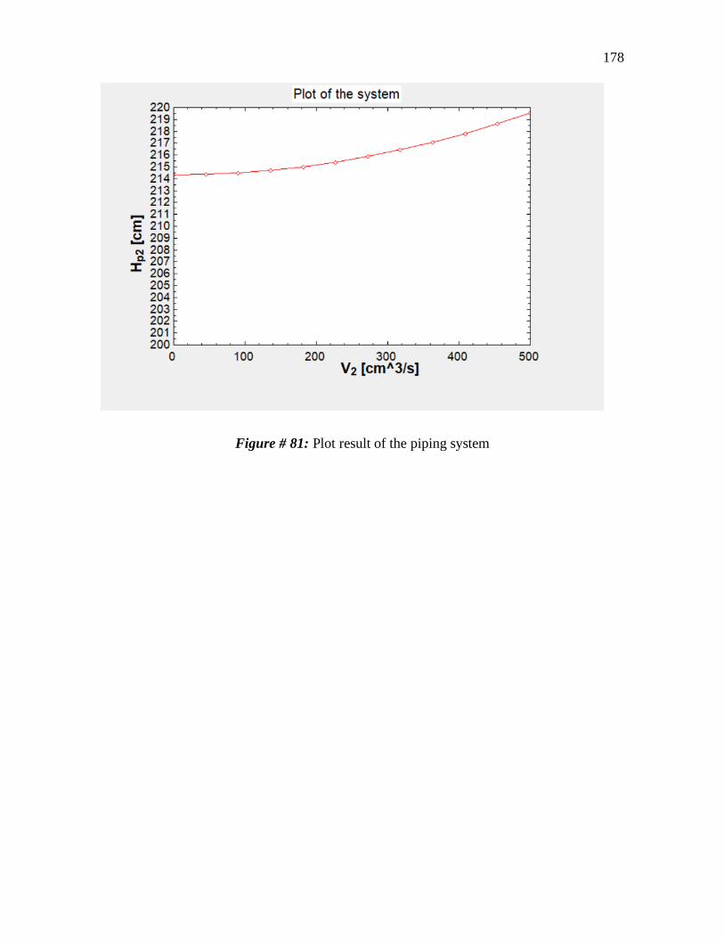
178
Figure # 81: Plot result of the piping system

179
Maintenance and Operation Manual
Data sheet
Table # 34: Data Sheet of the Beer Bottle Washer Machine
Parameters Description
Production Rate 290 bottles and 2 barrels per day. (Minimum
required 80 bottles and 2 barrels per day)
Bottle type Major diameters glass bottles from 60 to 73
millimeters
Rinsing time
(Water) 5 minutes
Rinsing time
(NaOH) 5 minutes
Water
temperature 85 ℃ ± 5 ℃
NaOH
Temperature 30℃ ± 5℃
Pump • Power: 0.4024 kilowatts

180
• Speed: 1750 RPM
• Type: End Suction
• Size: 1-1/2 X 1-6 AA
• Impeller Size: ∅ 5 𝑚𝑚𝑚𝑚𝑖𝑖ℎ𝑒𝑒𝑠𝑠
• 1 pump per washing station
Water and
NaOH Flow
Rate
99.6𝐿𝐿𝑚𝑚𝑚𝑚𝑚𝑚 ± 1
𝐿𝐿𝑚𝑚𝑚𝑚𝑚𝑚
Water Average
Pressure 0.077 kilopascal
NaOH Average
Pressure 0.055 kilopascal
Dimensions of
the machine
• Width: 2170.65 millimeters
• Depth: 620 millimeters
• Height: 756.26 millimeters
Water pipes Stainless steel 440C ∅ 1.25 𝑚𝑚𝑚𝑚𝑖𝑖ℎ𝑒𝑒𝑠𝑠
Water
distributor pipes Stainless steel 440C ∅ 1 𝑚𝑚𝑚𝑚𝑖𝑖ℎ

181
NaOH pipes Stainless steel 440C ∅ 1.25 𝑚𝑚𝑚𝑚𝑖𝑖ℎ𝑒𝑒𝑠𝑠
NaOH
distributor pipes Stainless steel 440C ∅ 1 𝑚𝑚𝑚𝑚𝑖𝑖ℎ
Rack Height 107 mm
Rack
Dimensions 374 x 507 mm
Equipment 2 Bottle-holder racks
Electrical
Connection 220V AC
Tank volume
(Water and
NaOH)
66.99 Liters
Water Heater 2 Electrical resistances of Stainless Steel 304 with
an input power of 6 Kilowatts
Part Description

182
Table # 35: List of Parts
Part
Number
Quantity Part Name
1 1 Reservoir Tank
2 2 Pipe Pump-Elbow
3 4 Piping Elbow
4 2 Pump
5 2 Pipe Elbow-Tank
6 2 Pipe Tank-Elbow
7 2 Pipe Pump-Elbow
8 2 Water Distributor Pipe
9 2 Parker Brass Ball Valve
XV520P
10 2 Bottle Rack
11 24 Glass Bottle
12 34 Ferrule

183

184
Figure # 82: List of parts of Bottle Washer Machine

185
Installation
The bottle washing machine is made up of the following parts
820 mm x 620 mm x 500 mm Stainless Steel Tank
4 - Ø 1 ¼ in Piping elbows
2 - Ø 1 ¼ in x 91.75 mm pump – elbow pipes.
2 - Ø 1 ¼ in x 194 mm elbow - tank pipes.
2 Ø 1 ¼ in x 80.65 mm tank-elbow internal pipes.
2 - Ø 1 in water Distributor Pipes
16 - Gaskets (Plus 16 spare gaskets)
14 - Clamps
2 - Racks
40 - Elastic cords
48 - Ø 5.23 mm x 25 mm Nozzles
1 - 0.4024 kW Pump, 99.6 L/min
2 - 6kW Stainless steel coils
2 - ¼ in Ball Valves 1
Electronic control system
Panel control box
2 - 1 ¼ Hoses with a ferrule adapted
The following conditions described on the installation piping plan are necessary:
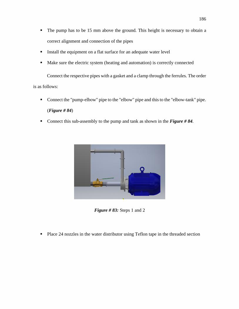
186
The pump has to be 15 mm above the ground. This height is necessary to obtain a
correct alignment and connection of the pipes
Install the equipment on a flat surface for an adequate water level
Make sure the electric system (heating and automation) is correctly connected
Connect the respective pipes with a gasket and a clamp through the ferrules. The order
is as follows:
Connect the "pump-elbow" pipe to the "elbow" pipe and this to the "elbow-tank" pipe.
(Figure # 84)
Connect this sub-assembly to the pump and tank as shown in the Figure # 84.
Figure # 83: Steps 1 and 2
Place 24 nozzles in the water distributor using Teflon tape in the threaded section

187
Figure # 84: Colocation of Nozzles
Connect the "tank-elbow" pipe to the "elbow" pipe and this on the inside of the tank
(Figure # 86)
Figure # 85: Step 4
Connect the water distributor to the previous sub-assembly (Figure # 87)
Connect the elastic cables to the eyebolts incorporated in the rack (Figure # 87)
Place the rack in the tank by inserting its four rods into the four holes in the top of the
tank (Figure # 87)

188
Figure # 86: Steps 5, 6, 7
Repeat these steps for the other side of the tank
Attention: Electrical installations need to be performed by a licensed technician!
Preheating Process
The preheating process is the final step prior the operation of the Beer Bottle Washing
Machine. This process is quite important due to the necessity of using water heated up to 85
degrees Celsius during the Washing process. The BRC standard suggests using hot water
during the disinfection and washing process of any bottles in the Food Industry. This because
hot water can easily clean and remove some of the most common food scraps. The preheating
process must take place once the user has already finished all the steps described in the
¡Error! No se encuentra el origen de la referencia. section. This because the Beer Bottle
Washing Machine has to be totally assembled before starts operating. It is recommended for
the user to double check if the installation process was made in a proper way in order to avoid
any kind of leaking trough the piping system. Double checking the correct installation of the
device will also avoid losing heated water during the operation of the Beer Bottle Washing
Machine.
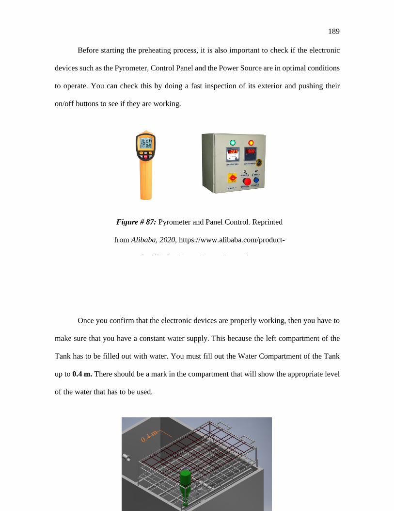
189
Before starting the preheating process, it is also important to check if the electronic
devices such as the Pyrometer, Control Panel and the Power Source are in optimal conditions
to operate. You can check this by doing a fast inspection of its exterior and pushing their
on/off buttons to see if they are working.
Once you confirm that the electronic devices are properly working, then you have to
make sure that you have a constant water supply. This because the left compartment of the
Tank has to be filled out with water. You must fill out the Water Compartment of the Tank
up to 0.4 m. There should be a mark in the compartment that will show the appropriate level
of the water that has to be used.
Figure # 87: Pyrometer and Panel Control. Reprinted
from Alibaba, 2020, https://www.alibaba.com/product-
d t il/S l W t H t I i

190
In case that the water mark is not legible, you can measure a height of 0.4 m from the
bottom of the Tank in order to assure the proper water volume i.e. 84 L. This is quite
important because all the parameters are based in this water volume. So, in order to have a
proper operation of the device, the user must guarantee a Volume of Water of 84 L.
Figure # 89: Water tank

191
When the Water Container is filled out with 84 L of Water, the user should wait for
5 minutes before turning on the Preheating system. During this time, the user must check the
device in order to find any place with water leaking. If there is no one, then, the user must
turn on the Preheating System. This can be done by pushing the blue button of the control
panel:
The preheating process will be performed for 45 minutes. So, the user must take in
consideration this time in order to plan his/her activities in a proper way.
As said before, the preheating process is going to take 45 minutes. This time is needed
to heat water from its original temperature up to 85 Degrees Celsius. Their power input is
controlled by the temperature of the water. An Electronic Control System was set up in a
PLC contained in the Control panel. This system is connected with a pyrometer in order to
Figure # 90: Start Button . Reprinted from Alibaba, 2020,
https://www.alibaba.com/product-detail/Custom-high-accuracy-indoor-control-
panel_62408482217.html?spm=a2700.galleryofferlist.0.0.70931d03sa0Hnn&s=p

192
know the water temperature at the very top. There is also a timer in the Control Panel that
lets the user know the time required for the Water to reach the desired temperature.
Attention: Do not touch the Surface of the Tank!!
During the preheating process, the user has to be aware that the Surface of the Tank
will be very hot. Even if the Electric Resistances are located at the bottom part of the Tank,
the surfaces near them will be very hot. For this reason, it is important for the user to not
touch these parts.
Once the temperature of the Water reaches 85 Degrees Celsius, an alarm will sound
in order to let the user know that the Preheating process has ended. Then the user can start
operating the device and wash the beer bottles. But, before that, the user has to follow the
steps described in the next section.
Figure # 91: Timer. Reprinted from Alibaba, 2020,
https://www.alibaba.com/product-detail/Custom-high-accuracy-indoor-control-
panel_62408482217.html?spm=a2700.galleryofferlist.0.0.70931d03sa0Hnn&s=
p

193
Pump and flow rate setting
When the user wants to start the pump, first must verify that the entire system is
tightened in all its joints and fittings. It is important to verify at least twice that the pump
connector is adjusted because in case of a failure in this connector, accidents could be
produced.
Once all the evaluations are done, the tanks must be filled up to 40 cm (Where a red
line must be marked), if the system is not filled up to this level, the water inlet will not be
enough to support the desired flow rate specified at the data sheet. Also, the adequate quantity
of water will avoid the system to cavitate and maintain the impeller of the pump in good
conditions for a long time.
Figure # 92: Pump controller System. Reprinted from Alibaba, 2020,
https://www.alibaba.com/product-detail/Development-board-Arduinos-UNO-R3-
atmega328p_60838481820.html?spm=a2700.galleryofferlist.0.0.2dfd7d0ff8PjA9
&s=p
A C B

194
The pump controller is a user-interface system that allows to set the Rinsing time and
also has an emergency stop system that in case of failure must be actioned by the operator.
The control interface contains 3 blocks. The first block A (illustrated with blue) is the
interface that allows to set the time. The times comes from a minimum of 1 minute and a
maximum of 99 minutes. The increments of time are programmed to increase or decrease by
30 seconds. In the LCD minutes and seconds are showed. Time goes decreasing according
to the time programmed at the beginning. Block B (illustrated with orange) has the
emergency stop button that will stop the pump in case that the operator detects a failure on
the system. Block C (illustrated with green) contains a switch and a light. When the system
is operating, the red light at Block C, will be ON. At the high state (ON), the pump will be
working at the flow rate of 99.6 [L/min].
Notes: Consider fixing the pump to the floor or at least adjust the pump because in
some occasions, pump could be started very hard and push the system and have unnecessary
movements that could put in danger the integrity of the operators.
Troubleshooting
The bottle washer machine is design for easy use. However, there are some problems
the machine could suffer during or prior its operation. There are two types of failures this
machine may go through. Procedure problems and operational problems. The firs problem
type occurs when the operator missed the correct process to ensemble or handle the machine.
In the other hand, the operational problems may occur when a machine accessory is in failure.
This can happen when an item has reached a certain level of ware and it has to be replaced
or has be under maintenance.

195
Under this differentiation, five problems have been analyzed and cataloged as
primordial for the operation of the bottle water machine:
Alignment problem
An alignment problem refers specifically to the bottle-nozzle alignment. It is
considered a procedure problem. The distributor pipe, where the nozzles are located, has been
design so the part of the nozzles enter exactly, with very small tolerance, into the bottles
mouth. There are various bottle types that can fit into the bottle-holder rack. However, the
design was made for the 335 ml and 750 ml long neck beer bottles. This doesn’t mean that
other bottles won’t be compatible with the structure.
If an alignment problem presents it can occur because of two different factors. The
first one is that the bottle is not correctly fastened, this occurs because in the upper part of
the rack the tension cables are too loose avoiding the bottle can be placed in the correct
position to be aligned with the nozzles. The tension cables allow that different kinds of bottles
can be placed and secured to the structure, if any of these are loose could involve alignment
problems or a more serious one which is the abandonment of a bottle of its position due of
the water pressure during the washing process.
The second factor of the alignment problem is the bottle is not compatible with the
rack. There is a significant amount of different glass bottles for the beverage industry. Some
of them may not adapt to the structure because of geometry problems like the bottle neck or
its body inhibit the bottle to be correctly placed in the structure. If the procedure to place the
bottles in the rack has been done correctly, reviewed and no problem has been found then the
rack is not compatible with that kind of bottle shape.

196
Clamping problems
The clamping problems can occur in two different systems: at the bottle-holder rack
and in the piping systems and at the piping system. It is considered a procedure problem. The
first failure was already mentioned in the previous sections. This occur when the tension
cables used to fasten the bottle for the process is too loose. Each cable along and breadthways
the structure has, at its both ends, screw mechanisms to adjust the cable to the correct tension
so it can correctly hold the bottle for the process.
The second problem, at the piping system, occurs at the piping joints. Since all the
pipe is detachable, in every joint it has a clamp which allows the accessories to remain
together while operating and enable a very easy and fast dismantling process for cleaning or
maintenance operations. The clamp is secured by torque pressure in the screw each clamp
has. If a joint is not correctly clamped, it can provoke leaking in the system or an abrupt
rupture in the joints which can be very dangerous for the operation personal.
Leaking problems
The leaking problem, as mention, is part of the procedure problems. Leaking may
occur when a clamp is not well secured as a result of a lack of torque while securing the
screw mechanism in the clamps. However, if clamping procedure after a cleaning or
maintenance process is the correct, then a problem can be caused by a defective clamp.
Damage can occur in the screw mechanism with time because of usage, applying a very
excessive force on it, or because heavy blows or falls suffered, which can deform the
mechanism avoiding it can mate as it should to the joint.
197
Corrosion problems
Consider as an operational problem, the corrosion in the material can be a very serious
problem if not properly taken care off. The pipes will be operating with two different kind of
liquids, caustic soda and water, at high temperatures that can variety between 75-90 ºC.
Although the material used at the pipes is stainless-steel, a very high corrosion resistant
material, a little bit of corrosion is expected in a long-term use. With time, the pipes will
have to enter to maintenance process for corrosion elimination. This phenomenon will
depend on the cycles quantity the machine will be exposed to and how frequent the pipes are
cleaned. With good maintenance, the pipes wont’s suffer any important wear during a
significant amount of time.
Pump problems
Another possible operational problem can be suffered at the pump. Wear is a problem
most materials and machines suffer. The pumps used at the system will suffer wear at
different levels depending on the operation conditions and the operating cycles. If the
machine is constantly operating at its maximum capacities, the wear will occur before than
if the machine is operating at normal and controlled conditions. However, this mechanical
phenomenon will occur sooner or later in long-term. The pumps should be maintained and
analyzed for possible damage every three months. A wear in the pump can cause cavitation
in the system damaging the pipes and its joints accessories. Each pump has its own
operational and maintenance manual which should be followed for every process.
Heating failure
A heating problem is considered as operational. It may occur when the heating
resistance has reached a certain level of were due to usage. Depending on the washing cycles

198
the machine will perform, the resistance will have a higher or lower wear level. However, a
resistance failure is not expected to occur in a short time term since the design of the heating
system was considering for a high stress during the cycles.
The heating system can also fail because of a circuit damage. This process is all
automatized so there is the possibility that one of the many accessories incorporated into the
circuit may fail because of overheating, wear, or any accident that may damage the control
electrics.
Electric problems
Electric failures are another kind of problems considered as operational. Process like
water heating or the pump control are all automatized which involves a considerable number
of electronic items. Any component is exposed to suffer wear with use, some components
are made to last longer than others but eventually the components will have to be maintained
if possible or replaced for new ones. Also, damage can occur in internal components due to
overheating caused by bad connections or external accidents which involve any electrical
component.
The machine has to be installed in a place were any connection or electrical
component is well secured to avoid any accident which can potentially damage the
automatized system. Having loose cables in the flor can produce accidents like people
tripping on them harming themselves and damaging the system. Also, if having leaks, the
loose cables could produce short-circuit which can cause terrible safety problems for the
personal.

199
Troubleshooting Solutions
The Troubleshooting solutions can be seen at Table # 25 at the Appendix B –
Project Management.
Maintenance of the piping system and identification of leaks
The stainless-steel piping system is made up of several sections due to the
continuous cleaning that must be carried out. The parts of this system are connected by
means of ferrules and clamps that allow their adjustment. Rubber gaskets are placed in
the middle of these two components that do not allow the liquid to filter and escape to the
outdoors. These gaskets can wear out over time and allow liquid to pass through. The set
of spare parts includes a set of 16 packages that must be replaced if this problem occurs.
If there are water leaks on the tank divider plate or pipes. Contact the designer.1
It is possible find another water leak in the thread of the nozzles. Therefore, it is
recommended to use Teflon tape to avoid this problem. If this problem occurs in the
future, replace the Teflon tape. It is important to carry out the internal cleaning of the
pipes using a chemical cleaner that is available in the hardware stores, making sure that
there are no solids and residue layers that can cause corrosion of the material. Perform
this cleaning periodically. Change the caustic soda every week or depending on the
number of cleaning cycles performed If the leaking is located at the inside, consult a
specialist technician for repair (Not at the joints)
Structural management
The bottle-holder rack is the simplest system of the machine. The structure can
easily resist more than 10 [kg] in terms of bottles weight or a stress of more than 33
[MPa]. The structure is design for a certain bottle type (335 ml and 750 ml long neck beer
200
bottles). However, it can easily hold a large number of different bottle types. For a correct
use of this component, follow the next steps:
Each bottle placed in its individual compartment has to be positioned upside-
down. This means the bottle neck has to be facing the floor.
To secure ta bottle to the structure tremble the cables at the top of the rack making
sure they are being adjusted around the bottle body.
To adjust the cables, use the screw device placed at the sides of the structure, turn
them until the cables are trembled. Don’t overstrain the screw this could damage
the device and the bottles.
Confirm that each bottle is well secured by trying to move it or gently trying to
lift it. If well secured the bottle should be stay still in its place.
Note: When a new and different bottle is going to be tested at the rack it is
important to do it as gently as possible. Under no circumstances a bottle has to be forced
to fit in a compartment. This can deform part of the structure making it useless until its
fixed.
Once the structure is loaded with bottles, it has to be placed over the tank for the
washing process. The structure has four legs which fit exactly in the four holes placed in
the top sides of the tank. There are two handles in each side of the structure, so it has been
placed over the tank by two people. The rack can be manipulated by only one person, but
for safety reasons it is not recommended to do so.
Once the structure is placed over the tank follow these instructions:
Make sure it is well settled in the corresponding spots. The handles should be
pointing to the sides of the tank, breadthways.
Re-check the bottles are still well secured to the rack.
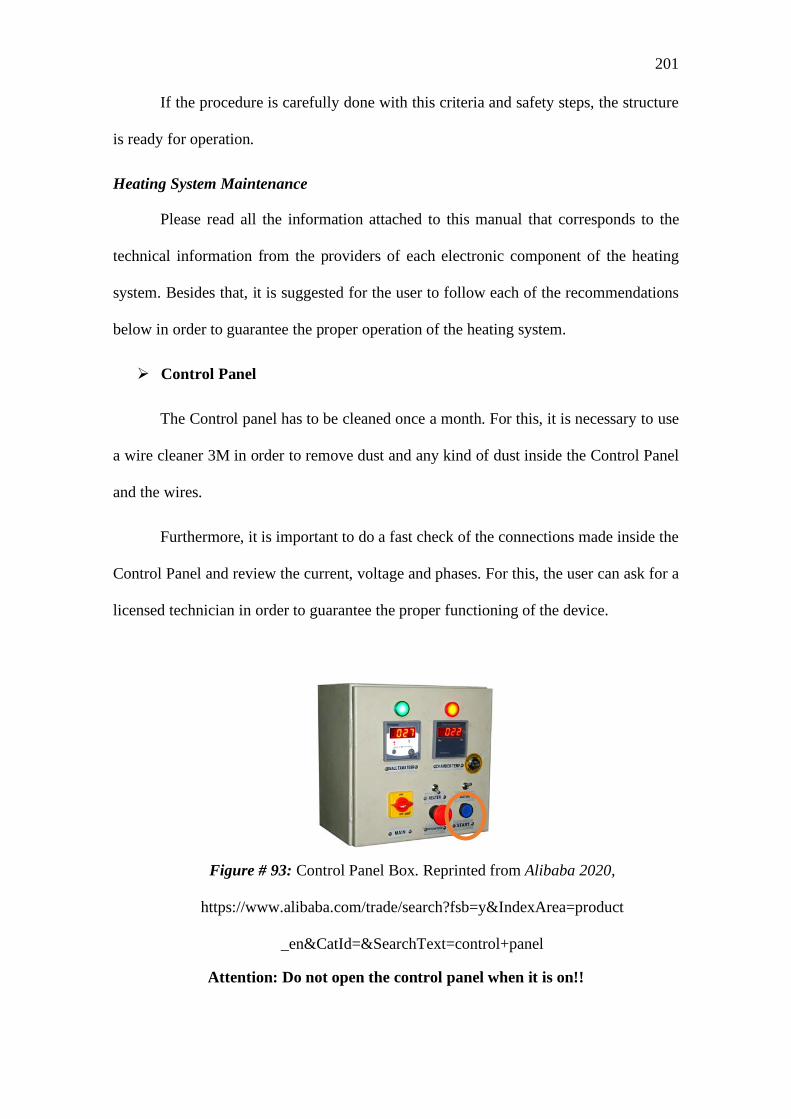
201
If the procedure is carefully done with this criteria and safety steps, the structure
is ready for operation.
Heating System Maintenance
Please read all the information attached to this manual that corresponds to the
technical information from the providers of each electronic component of the heating
system. Besides that, it is suggested for the user to follow each of the recommendations
below in order to guarantee the proper operation of the heating system.
Control Panel
The Control panel has to be cleaned once a month. For this, it is necessary to use
a wire cleaner 3M in order to remove dust and any kind of dust inside the Control Panel
and the wires.
Furthermore, it is important to do a fast check of the connections made inside the
Control Panel and review the current, voltage and phases. For this, the user can ask for a
licensed technician in order to guarantee the proper functioning of the device.
Attention: Do not open the control panel when it is on!!
Figure # 93: Control Panel Box. Reprinted from Alibaba 2020,
https://www.alibaba.com/trade/search?fsb=y&IndexArea=product
_en&CatId=&SearchText=control+panel
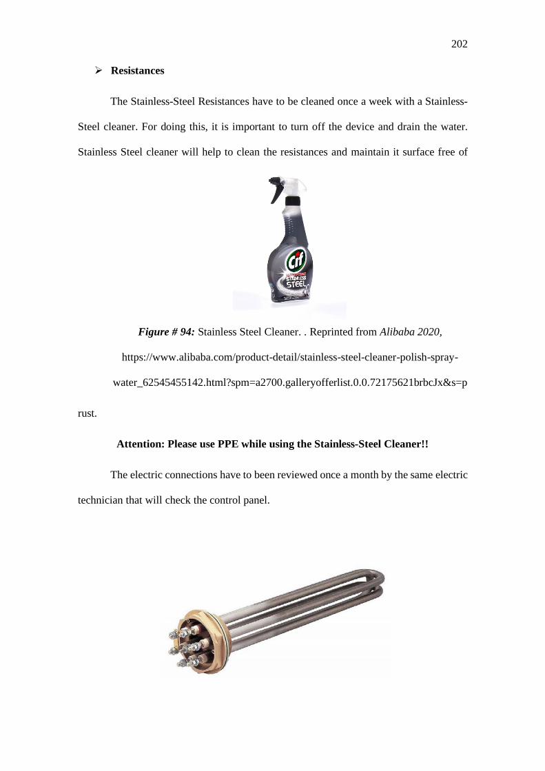
202
Resistances
The Stainless-Steel Resistances have to be cleaned once a week with a Stainless-
Steel cleaner. For doing this, it is important to turn off the device and drain the water.
Stainless Steel cleaner will help to clean the resistances and maintain it surface free of
rust.
Attention: Please use PPE while using the Stainless-Steel Cleaner!!
The electric connections have to been reviewed once a month by the same electric
technician that will check the control panel.
Figure # 94: Stainless Steel Cleaner. . Reprinted from Alibaba 2020,
https://www.alibaba.com/product-detail/stainless-steel-cleaner-polish-spray-
water_62545455142.html?spm=a2700.galleryofferlist.0.0.72175621brbcJx&s=p

203
Attention: Do not touch the surfaces located near the Resistances!!
The resistance can reach a temperature of 500 Degrees Celsius, so please use a
PPE for hot surfaces during the operation of the equipment
Pyrometer
The Pyrometer has to be reviewed and calibrated every 6 months. For this, it is
necessary to bring it to a licensed calibration center. Also, when cleaning, please do not
touch the front surfaces where the laser is located.
Figure # 95: Stainless Steel Resistance. Reprinted from Alibaba 2020,
https://www.alibaba.com/product-detail/electrical-resistance-tubular-for-water-
heater_60023836658.html?spm=a2700.galleryofferlist.0.0.5925e4abxDOJI2&s=p
Figure # 96: PPE Needed. Reprinted from Alibaba 2020,
https://www.alibaba.com/product-detail/electrical-resistance-tubular-for-water-
heater_60023836658.html?spm=a2700.galleryofferlist.0.0.5925e4abxDOJI2&s=p

204
Safety operation
A safe operation is very important, mainly in this machine which works with very
high temperature and has important electrical risks which can cause serious problems to
the operator’s wellness. To avoid and reduce to its maximum the risks, the operator has
to follow the next steps.
The following safety equipment has to be used all times during the machine
operation:
- Thermal gloves, to manipulate the structure after use.
- Protective glasses
- Apron
- Industrial boots
The bottle-rack has to be full loaded for every cycle. The 24 bottles have to be
inside the rack. There is not possible no leave a nozzle without a bottle because,
while operation, a hot water jet will be out freely, and it can reach the operator or
the electrical system causing serious damage.
Prior the preheating procedure, make sure the nozzles are all aligned with the
bottles in the rack, and part of them are inside the bottles. This avoid the risks of
having hot water jets uncontrolled during the washing process.
Before the preheating procedure, run both systems to make sure the water jets are
hitting bottles at their inside and there are no leaks in the system.
Make sure there are no loose cables or water under the machine. This can cause
short-circuits.
Assure the bottles are well fastened to the structure and make a one-minute run
test before the preheating process to certify the bottles won’t come off.
Secure the pump to the floor so it won’t move during operation. Consider that the system will operate under high pressure values.

205
Meeting Minutes
Figure # 97: first meeting minute
Figure # 989: second meeting minute