dustin chan selected works
DESCRIPTION
23-Aug-2015 PortfolioTRANSCRIPT

DustinChan
Selected Works
Resume
Personal Statement
Selected Visual Works
Selected Produced Works
Portfolio Inventory
University of Hawai'i, Manoa, 2008 - Present Bachelor of Environmental Design (Completed 2014) Doctor of Architecture Degree Candidate
University of Washington, 2013, Winter - Fall
Maryknoll High School, 2004 - 2008
Intern Architect, University of Hawaii: Campus Housing Operations, Mar 2014 - Jan 2015
Production of as-built drawing sets and 3D models for restoration & renovation, site measurements, etc as RFQ. Field work includes but not limited to measurements, picture cataloging, and scheduling.
HURRIPLAN: Resilient Building Design for Coastal Communities
Safety Training for Harness & Tie-Offs
LEED GA (Dec 2015)
Certifications
Education
Experience
issuu.com/DustinTheChanlinkedin.com/in/DustinTheChan
Dustin K.L. Chan
(808) 398 - 1680
Res
ume
02
Intern Architect, University of Washington: Campus Engineering, Mar - Dec 2013
Production of as-built drawing set for restoration & renovation, site measurements etc. Field work includes but not limited to databasing ballards, light posts, storm drains, using LiDAR, and GPS location tracking. Additionally, I was trained to use safety harnesses for the roofs project.
Money Processor, First Hawaiian Bank, June 2009 - Oct 2012
Independently count and verify customer transactions which include large cash amounts and confidential information handling using judgment and discretion while maintaining an efficient, quick, and accurate pace. Additionally I was trained as a Transaction Reciever and Change Order Processor.
Familiar Programs: Chinese (Verbal Communication)
Model-Crafting
Data Organization
Management 230, U.Wash
Skills
Personal Statement
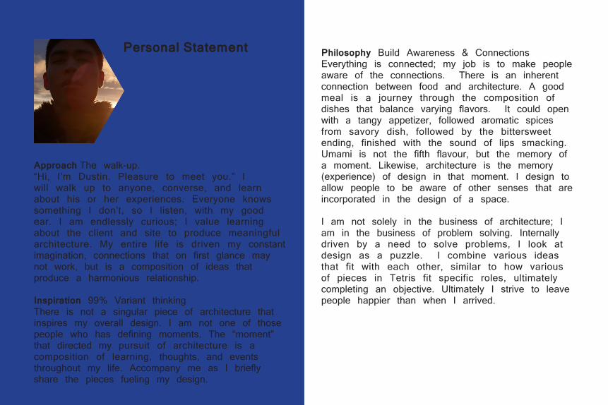
Approach The walk-up.“Hi, I’m Dustin. Pleasure to meet you.” I will walk up to anyone, converse, and learn about his or her experiences. Everyone knows something I don’t, so I listen, with my good ear. I am endlessly curious; I value learning about the client and site to produce meaningful architecture. My entire life is driven my constant imagination, connections that on first glance may not work, but is a composition of ideas that produce a harmonious relationship.
Inspiration 99% Variant thinkingThere is not a singular piece of architecture that inspires my overall design. I am not one of those people who has defining moments. The “moment” that directed my pursuit of architecture is a composition of learning, thoughts, and events throughout my life. Accompany me as I briefly share the pieces fueling my design.
Philosophy Build Awareness & ConnectionsEverything is connected; my job is to make people aware of the connections. There is an inherent connection between food and architecture. A good meal is a journey through the composition of dishes that balance varying flavors. It could open with a tangy appetizer, followed aromatic spices from savory dish, followed by the bittersweet ending, finished with the sound of lips smacking. Umami is not the fifth flavour, but the memory of a moment. Likewise, architecture is the memory (experience) of design in that moment. I design to allow people to be aware of other senses that are incorporated in the design of a space.
I am not solely in the business of architecture; I am in the business of problem solving. Internally driven by a need to solve problems, I look at design as a puzzle. I combine various ideas that fit with each other, similar to how various of pieces in Tetris fit specific roles, ultimately completing an objective. Ultimately I strive to leave people happier than when I arrived.
Selected Visual Works

06
10
12
16
Selected Visual Works
Project M: LightHouse
Sponge
Gateway
Multi-Stoy Container Home
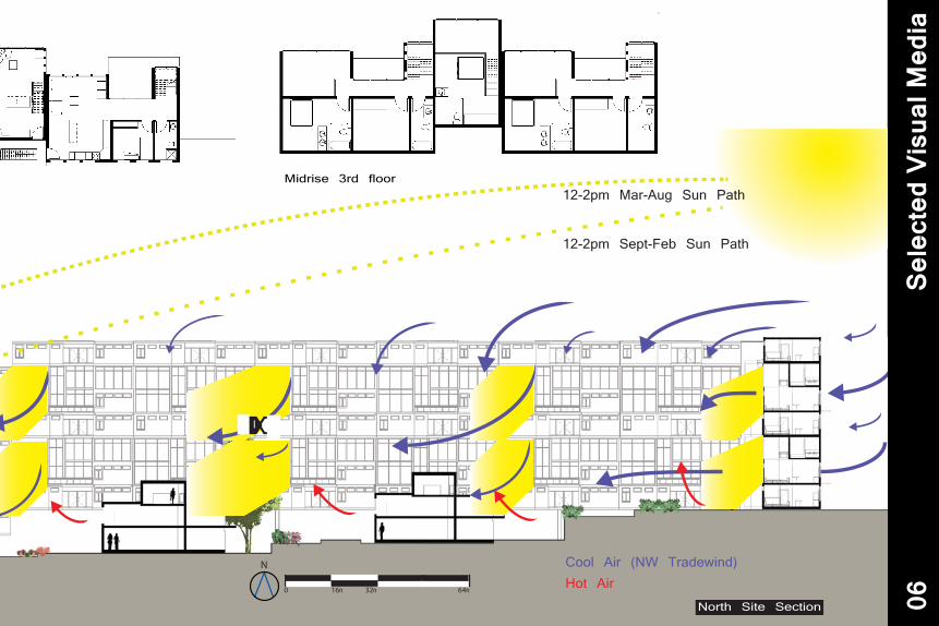
Cool Air (NW Tradewind)Hot Air
12-2pm Mar-Aug Sun Path
12-2pm Sept-Feb Sun Path
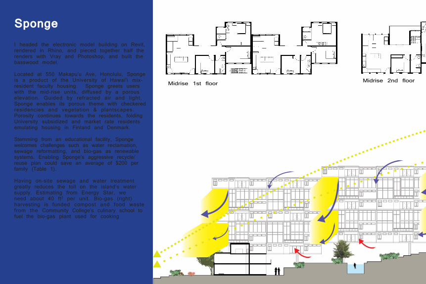
Midrise 2nd floorMidrise 1st floor
I headed the electronic model building on Revit, rendered in Rhino, and pieced together half the renders with Vray and Photoshop, and built the basswood model.
Located at 550 Makapu'u Ave, Honolulu, Sponge is a product of the University of Hawai'i mix-resident faculty housing. Sponge greets users with the mid-rise units, diffused by a porous elevation. Guided by refracted air and light, Sponge enables its porous theme with checkered residencies and vegetation & plantscapes. Porosity continues towards the residents, folding University subsidized and market rate residents emulating housing in Finland and Denmark. Stemming from an educational facility, Sponge welcomes challenges such as water reclamation, sewage reformatting, and bio-gas as renewable systems. Enabling Sponge’s aggressive recycle/reuse plan could save an average of $200 per family (Table 1).
Having on-site sewage and water treatment greatly reduces the toll on the island’s water supply. Estimating from Energy Star, we need about 40 ft2 per unit. Bio-gas (right) harvesting is funded compost and food waste from the Community College’s culinary school to fuel the bio-gas plant used for cooking.
Sponge
Cool Air (NW Tradewind)Hot Air
12-2pm Mar-Aug Sun Path
12-2pm Sept-Feb Sun Path
North Site Section
N
0 8ft 16ft 32ft
0 4ft 8ft 16ft
N
N
N
0 16ft 32ft 64ft
N
Midrise 3rd floor
1
Sele
cted
Vis
ual M
edia
06

Users leisurely stroll through Sponge’s urban garden park-esque property. NE perspective rendering.
Water reclamation is enabled through the collection of sewage in a digester, filtered through constructed plantscapes, then a secondary drip system filter, for reuse either as potable water or as irrigation, car washing, or collected in a pond. Residents lead by example, garbage is divided into compost, recyclables, and trash.
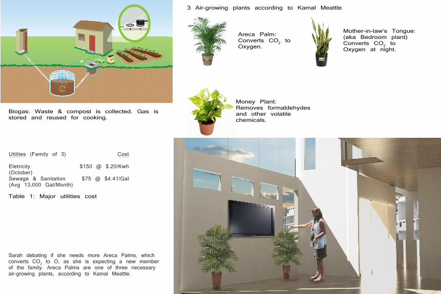
Sarah debating if she needs more Areca Palms, which converts CO2 to O, as she is expecting a new member of the family. Areca Palms are one of three necessary air-growing plants, according to Kamal Meattle.
Utilites (Family of 3)
Eletricity(October)Sewage & Sanitation(Avg 13,000 Gal/Month)
Cost
$150 @ $.20/Kwh
$75 @ $4.41/Gal
Table 1: Major utilities cost
3 Air-growing plants according to Kamal Meattle
Areca Palm: Converts CO2 to Oxygen.
Mother-in-law’s Tongue:(aka Bedroom plant)Converts CO2 to Oxygen at night.
Money Plant:Removes formaldehydes and other volatile chemicals.
Biogas: Waste & compost is collected. Gas is stored and reused for cooking.

Perspective View of 1/8”:1’ Model
Project M is a case study on Alberto Campo Baeza’s Casa de Blas in southern Barcelona, Spain. Alberto Campo Baeza views light as the determining factor in defining space. LightHouse emulates the interplay of light and gravity of Casa de Blas. The gaps running through the side and center of the house intensifies the light depending on the time of day.
LightHouse’s physical model used a puzzle piece connection, minimizing glue to the plexiglass plastic dowels. The physical model explored CNC routing (landscape), laser cutting (LightHouse physical model), material exploration (textured matt board, plexiglass, various paints). Additionally, the project granted the opportunity to explore digital renderings (Photoshop, V-Ray’s
Project M: LightHouse

Exploration of light on stairs 1
Meditation Room Ceiling openings intensify light as it is filtered into the second floor.
Sele
cted
Vis
ual M
edia
10

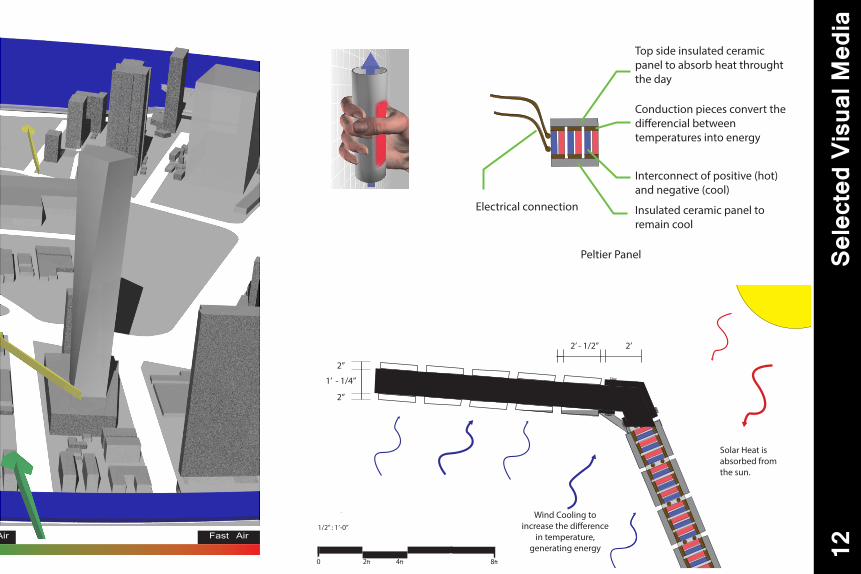
Wind Flow DiagramSlow Air
Parking
Public: Retail Restaurant
Commercial: Office
Private: Residential Hotel
BACKGROUND:In 2049, a law is passed stating no one entity can dictate necessary resources such as water or electricity (energy). In 2050, sustainability is an integral part of society. Gateway generates electricity through the conduction process of energy exchange between two varying temperatures, amplified by the wind chimney and solar heat. The project stemmed from the idea to be off gird, even feeding power back
HOW GATEWAY GENERATES POWER:The solar shade also acts as a primary energy generating source. Peltier panels absorb heat from solar radiation and convert the differential in temperature between the hot and cool sides (see section-diagram, left). With the advancement in technology the panels are able to out generate solar panels, thus providing more energy per panel.
Concept:
Gateway
2’ - 1/2” 2’ 1”3”
1’ - 1/4”
2”
Peltier Panel
Top side insulated ceramic panel to absorb heat throught the day
Conduction pieces convert the di�erencial between temperatures into energy
Insulated ceramic panel to remain cool
Electrical connection
Interconnect of positive (hot) and negative (cool)
2”
0 8ft 16ft 32ft
N
0 4ft 8ft 16ft
N
0 16ft 32ft 64ft
N
0 32ft 64ft 128ft
0 32ft 64ft 128ft
N N
1/32” : 1’-0”
1/32” : 1’-0”
1/16” : 1’-0”
1/8” : 1’-0”
1/4” : 1’-0”
0 2ft 4ft 8ft
N
1/2” : 1’-0”
Solar Heat is absorbed from the sun.
Wind Cooling to increase the di�erence
in temperature, generating energy
Solar Heat is absorbed from the sun.
Wind Cooling to increase the di�erence
in temperature, generating energy
2’ - 1/2” 2’ 1”3”
1’ - 1/4”
2”
Peltier Panel
Top side insulated ceramic panel to absorb heat throught the day
Conduction pieces convert the di�erencial between temperatures into energy
Insulated ceramic panel to remain cool
Electrical connection
Interconnect of positive (hot) and negative (cool)
2”
Slow Air Fast Air
Sele
cted
Vis
ual M
edia
12
3’ - 6”4’ 2’ 3’ 3” 1/8”6’2’ - 6”
8”
3’
4”
11’
8”’
3” 7’-0” 2’-0”1/4” 1/4”6’
8”
3’ 3’
4”
11’
8”’
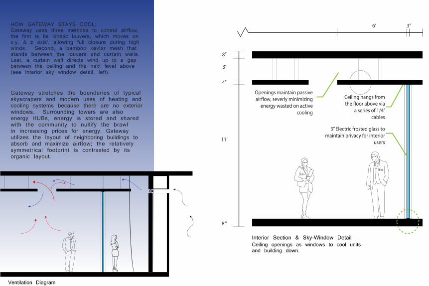
3” Electric frosted glass to maintain privacy for interior
users
Ceiling hangs from the �oor above via
a series of 1/4” cables
Bob
Erin
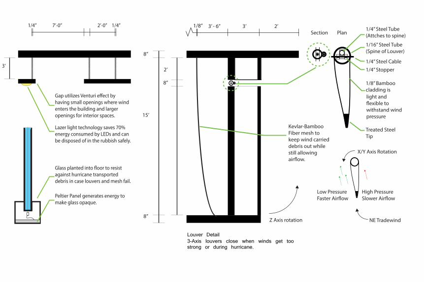
Gap utilizes Venturi e�ect by having small openings where wind enters the building and larger openings for interior spaces.
Lazer light technology saves 70% energy consumed by LEDs and can be disposed of in the rubbish safely.
Glass planted into �oor to resist against hurricane transported debris in case louvers and mesh fail.
Peltier Panel generates energy to make glass opaque.
Openings maintain passive air�ow, severly minimizing
energy wasted on active cooling
Interior Section & Sky-Window DetailCeiling openings as windows to cool units and building down.
Ventilation Diagram
HOW GATEWAY STAYS COOL:Gateway uses three methods to control airflow, the first is its kinetic louvers, which moves on x,y, & z axis', allowing full closure during high winds. Second, a bamboo kevlar mesh that stands between the louvers and curtain walls. Last, a curtain wall directs wind up to a gap between the ceiling and the next level above (see interior sky window detail, left).
Gateway stretches the boundaries of typical skyscrapers and modern uses of heating and cooling systems because there are no exterior windows. Surrounding towers are also energy HUBs, energy is stored and shared with the community to nullify the brawl in increasing prices for energy. Gateway utilizes the layout of neighboring buildings to absorb and maximize airflow; the relatively symmetrical footprint is contrasted by its organic layout.
3’ - 6” 2’ 3’ 1/8”
8”
2’
1/16” Steel Tube (Spine of Louver)
Section Plan
1/4” Stopper1/4” Steel Cable
15’
8”
8”
1/8” Bamboo cladding islight and �exible to withstand wind pressure
Treated Steel Tip
High PressureSlower Air�ow
Low PressureFaster Air�ow
NE Tradewind
X/Y Axis Rotation
Z Axis rotation
1/4” Steel Tube(Attches to spine)
Louvers Detailed Section
Kevlar-Bamboo Fiber mesh to keep wind carried debris out while still allowing air�ow.
3” 7’-0” 2’-0”1/4” 1/4”6’
8”
3’ 3’
4”
11’
8”’
3” Electric frosted glass to maintain privacy for interior
users
Ceiling hangs from the �oor above via
a series of 1/4” cables
Bob
Erin
Gap utilizes Venturi e�ect by having small openings where wind enters the building and larger openings for interior spaces.
Lazer light technology saves 70% energy consumed by LEDs and can be disposed of in the rubbish safely.
Glass planted into �oor to resist against hurricane transported debris in case louvers and mesh fail.
Peltier Panel generates energy to make glass opaque.
Openings maintain passive air�ow, severly minimizing
energy wasted on active cooling
Louver Detail3-Axis louvers close when winds get too strong or during hurricane.

1':100" scale model (Left)
1':1/2" scale model
The multi-Story container homes were designed to be a quickly constructible solution to the growing Honolulu population. Each floor can be taken apart and utilized elsewhere.
As part of the model building team, I led the team in designing accessible walkways such as stairs, elevator shafts, and accessible paths. After completing the walkways, I proceeded to work with other Doctorate students to stain and assemble three models, 1":100', 1":1/4", and 1":1/2". By selecting my teammates, we completed all three models within a week.
Multi-Story Container Home
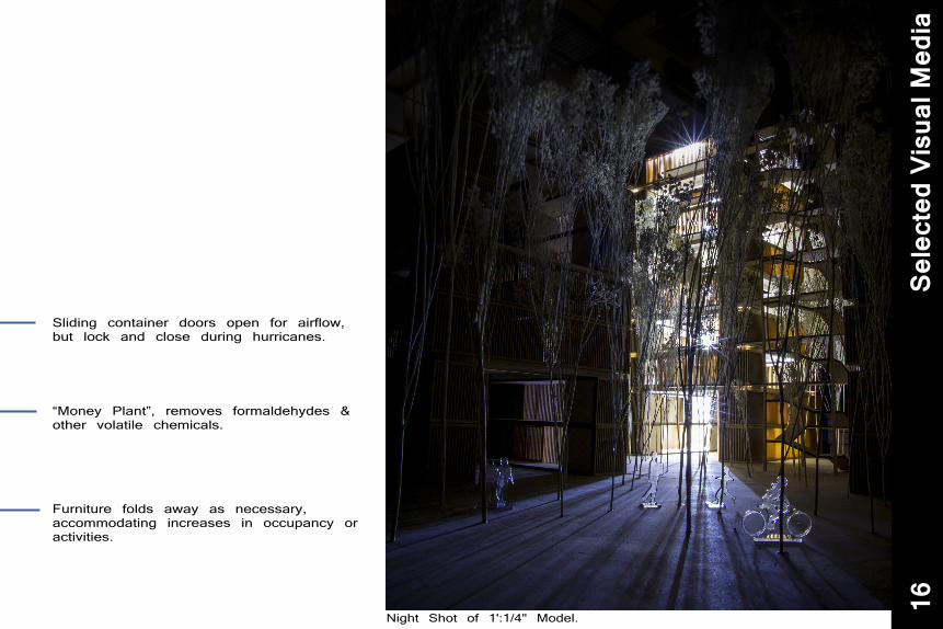
Sliding container doors open for airflow, but lock and close during hurricanes.
“Money Plant”, removes formaldehydes & other volatile chemicals.
Furniture folds away as necessary, accommodating increases in occupancy or activities.
Night Shot of 1':1/4" Model.
Sele
cted
Vis
ual M
edia
16

1':100" scale model Tower with Stairs.
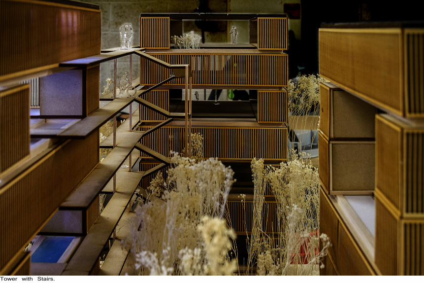
Tower with Stairs.

Selected Produced Works
Sele
cted
Pro
duce
d M
edia
20
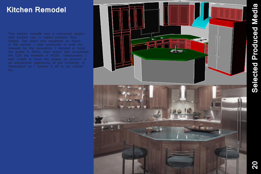
This kitchen remodel was a contracted project with Andrew Lee, a retired architect from Hawaii. The client only requested an island in the kitchen. I was contracted to draft the linework for the renovation. I decided to build the model in Rhino, then import and consolidate the CDs the linework in ACAD. Unfortunately I was unable to finish the project on account of an educational opportunity at the University of Washington so I handed it off to my partner Ky.
Kitchen Remodel
H
G
F
E
D
C
B
A
8 7 6 5 4 3 2 1
H
G
F
E
D
C
B
A
8 7 6 5 4 3 2 1
Drawing Sheet
A-1 of 2 sheets
Revision Log:
University of
Washington
Facilities Services
Campus E ngineeringServing today...preserving tomorrow
(1351)
Anderson H all - I nstallation of F all
Arrest Anchors
G3
G3D
R1
Scale: 1/8"=1'
16' 32'8'0'
1
Legend :
DS
RD
1 Roof No .Gutter No .
S
Scupper w / Downspout
Scupper
Roof Drain
Fall Anchor
RD Roof and Over�owDrains
1 Skylight No .
A
Guardrail
Seismic Joint
Roof Access
Ladder
Horizontal Lifeline w / Shock Absorber (S )
DavitD
Perspective View.
RD
R2
RDRD
R2A
G3A
RD
R2BRD
RD
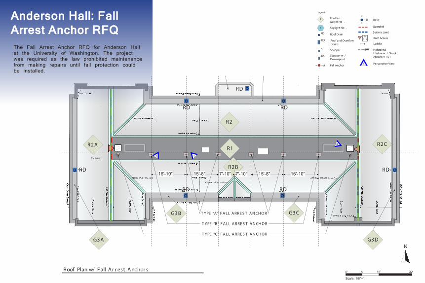
Gener al N ot es: 1) I nst allat ion of f all ar r est devices r equir es r emoval and pat ching of ex ist ing r oof ing mat er ial (see gr ey squar es on plan). Univer sit y f or ces shall r emove r oof ing t o ex pose ex ist ing concr et e (or wood) r oof deck, and pat ch wit h new compat ible r oof ing mat er ial af t er f all ar r est anchor s have been inst alled.
2) T ake car e t o pr ot ect ex ist ing met al f lashing and copper or nament al shapes wher e f all anchor s ar e locat ed close t o t hese element s. A ny damaged mat er ial shall be r emoved and r eplaced t o mat ch or iginal.
3) Phot os show gener al condit ion of t he r oof and/ or at t ic of t his building. Consider possible leaks when scheduling t he wor k and pr ot ect t he int er ior of t he building at all t imes.
4) Roof Plan is dr awn over a backgr ound of t he Recor d Roof Plan and st r uct ur al f r aming plan (when available) f or t his building. Ver if y t he locat ion of any ex ist ing, f r aming, r oof t op r oof dr ains, plumbing vent s, mechanical f ix t ur es, et c., and r epor t any conf lict s wit h pr oposed f all ar r est anchor s pr ior t o beginning wor k.
S t r uct ur al Gener al N ot es: 1) A ll st eel member s ar e t o be hot - dipped galvaniz ed af t er f abr icat ion. A ll f ast ener s t o be hot - dipped galvaniz ed. S t eel and f ast ener s t hat ar e inst alled below t he r oof st r uct ur e level need not be galvaniz ed.
2) S t eel Pipe shall be A S T M A 53, F y = 35 ksi. S t eel plat es and miscellaneous shapes shall be A S T M A 36.
3) F ield ver if y all ex ist ing const r uct ion. Do not scale plans or det ails t o det er mine dimensions.
4) F ull Penet r at ion (F P) welds shall have member pr epar ed wit h pr oper gr oove angle and r oot opening. Pr ovide backup bar or plat e f or all F ull Penet r at ion welds.
7'-10" 7'-10" 15'-8"15'-8" 16'-10"16'-10"
2x Joist
T YPE “C” F A LL A RRE S T A N CH O R
T YPE “B” F A LL A RRE S T A N CH O R
T YPE “A ” F A LL A RRE S T A N CH O R
Roof Plan w/ F all A r r est A nchor s
RD
R2C
G3CG3B
3
2 1
1 2 3
Drawn By:
Checked By:Approved By:Date:Work Order # :
Bezalel H o Dustin ChanT om PittsfordT om Berg15 – Oct – 2013
R3
H
G
F
E
D
C
B
A
8 7 6 5 4 3 2 1
H
G
F
E
D
C
B
A
8 7 6 5 4 3 2 1
Drawing Sheet
A-1 of 2 sheets
Revision Log:
University of
Washington
Facilities Services
Campus E ngineeringServing today...preserving tomorrow
(1351)
Anderson H all - I nstallation of F all
Arrest Anchors
G3
G3D
R1
Scale: 1/8"=1'
16' 32'8'0'
1
Legend :
DS
RD
1 Roof No .Gutter No .
S
Scupper w / Downspout
Scupper
Roof Drain
Fall Anchor
RD Roof and Over�owDrains
1 Skylight No .
A
Guardrail
Seismic Joint
Roof Access
Ladder
Horizontal Lifeline w / Shock Absorber (S )
DavitD
Perspective View.
RD
R2
RDRD
R2A
G3A
RD
R2BRD
RD
Gener al N ot es: 1) I nst allat ion of f all ar r est devices r equir es r emoval and pat ching of ex ist ing r oof ing mat er ial (see gr ey squar es on plan). Univer sit y f or ces shall r emove r oof ing t o ex pose ex ist ing concr et e (or wood) r oof deck, and pat ch wit h new compat ible r oof ing mat er ial af t er f all ar r est anchor s have been inst alled.
2) T ake car e t o pr ot ect ex ist ing met al f lashing and copper or nament al shapes wher e f all anchor s ar e locat ed close t o t hese element s. A ny damaged mat er ial shall be r emoved and r eplaced t o mat ch or iginal.
3) Phot os show gener al condit ion of t he r oof and/ or at t ic of t his building. Consider possible leaks when scheduling t he wor k and pr ot ect t he int er ior of t he building at all t imes.
4) Roof Plan is dr awn over a backgr ound of t he Recor d Roof Plan and st r uct ur al f r aming plan (when available) f or t his building. Ver if y t he locat ion of any ex ist ing, f r aming, r oof t op r oof dr ains, plumbing vent s, mechanical f ix t ur es, et c., and r epor t any conf lict s wit h pr oposed f all ar r est anchor s pr ior t o beginning wor k.
S t r uct ur al Gener al N ot es: 1) A ll st eel member s ar e t o be hot - dipped galvaniz ed af t er f abr icat ion. A ll f ast ener s t o be hot - dipped galvaniz ed. S t eel and f ast ener s t hat ar e inst alled below t he r oof st r uct ur e level need not be galvaniz ed.
2) S t eel Pipe shall be A S T M A 53, F y = 35 ksi. S t eel plat es and miscellaneous shapes shall be A S T M A 36.
3) F ield ver if y all ex ist ing const r uct ion. Do not scale plans or det ails t o det er mine dimensions.
4) F ull Penet r at ion (F P) welds shall have member pr epar ed wit h pr oper gr oove angle and r oot opening. Pr ovide backup bar or plat e f or all F ull Penet r at ion welds.
7'-10" 7'-10" 15'-8"15'-8" 16'-10"16'-10"
2x Joist
T YPE “C” F A LL A RRE S T A N CH O R
T YPE “B” F A LL A RRE S T A N CH O R
T YPE “A ” F A LL A RRE S T A N CH O R
Roof Plan w/ F all A r r est A nchor s
RD
R2C
G3CG3B
3
2 1
1 2 3
Drawn By:
Checked By:Approved By:Date:Work Order # :
Bezalel H o Dustin ChanT om PittsfordT om Berg15 – Oct – 2013
R3The Fall Arrest Anchor RFQ for Anderson Hall at the University of Washington. The project was required as the law prohibited maintenance from making repairs until fall protection could be installed.
Anderson Hall: Fall Arrest Anchor RFQ
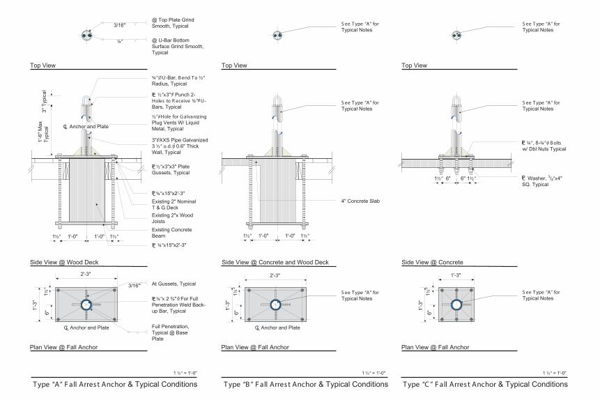
LC Anchor and Plate
6"
H
G
F
E
D
C
B
A
8 7 6 5 4 3 2 1
H
G
F
E
D
C
B
A
8 7 6 5 4 3 2 1
Drawing Sheet
A-2 of 2 sheets
Revision Log:
University of
Washington
Facilities Services
Campus E ngineeringServing today...preserving tomorrow
1
Legend :
DS
RD
1 Roof No .Gutter No .
S
Scupper w / Downspout
Scupper
Roof Drain
Fall Anchor
RD Roof and Over�owDrains
1 Skylight No .
A
Guardrail
Seismic Joint
Roof Access
Ladder
Horizontal Lifeline w / Shock Absorber (S )
DavitD
Perspective View
At Gussets, Typical3/16"
2'-3"
1½”
Full Penetration,Typical @ BasePlate
Plan View @ Fall Anchor
Side View @ Wood Deck
3/16"@ Top Plate GrindSmooth, Typical
@ U-Bar BottomSurface Grind Smooth,Typical
1'-6
"Max
Typi
cal
3"Ty
pica
l¼”
Top View
1'-0" 1'-0" 1½” 1½”
Existing 2"x WoodJoists
Existing 2" NominalT & G Deck
Existing ConcreteBeam
Side View @ Concrete and Wood Deck
Top View
1'-0" 1'-0" 1½” 1½”
1'-3
"
Side View @ Concrete
Top View
6" 6" 1½” 1½”
¾”x 2 ¾" For FullPenetration Weld Back-up Bar, Typical
PL
2'-3"
1½”
1'-3
"
S ee T ype “A” for Typical Notes
Plan View @ Fall Anchor Plan View @ Fall Anchor
S ee T ype “A” for Typical Notes
6"
1'-3"
1½”
1'-3
"
S ee T ype “A” for Typical Notes
¾”, 8-¾” B olts w/ Dbl Nuts TypicalPL
Washer, 3/8”x4"SQ. TypicalPL
S ee T ype “A” for Typical Notes
S ee T ype “A” for Typical Notes
S ee T ype “A” for Typical Notes
4" Concrete Slab
(1351)
Anderson H all - I nstallation of F all
Arrest Anchors
Drawn By:
Checked By:Approved By:Date:Work Order # :
¾”x15"x2'-3"PL
½”x3"x3" PlateGussets, TypicalPL
3" XXS Pipe Galvanized3 ½” o.d. 0.6" ThickWall, Typical
6"
½”x3" Punch 2-Holes to R eceive ¾” U-Bars, Typical
PL
½” Hole for G alvanizing Plug Vents W/ LiquidMetal, Typical
Anchor and PlateLC Anchor and PlateLC
¾”x15"x2'-3"PL
¾” U-Bar, B end T o ½” Radius, Typical
1 ½” = 1'-0"
T ype “A” F all Arrest Anchor & Typical Conditions1 ½” = 1'-0"
T ype “B ” F all Arrest Anchor & Typical Conditions1 ½” = 1'-0"
T ype “C ” F all Arrest Anchor & Typical Conditions
Bezalel H o Dustin ChanT om PittsfordT om Berg15 – Oct – 2013
