drawing section views and graphic patterns
TRANSCRIPT

EDT 310 - Drawing Section Views and Graphic Pattersn 1
Drawing Section Views
and
Graphic Patterns
Sacramento City College
EDT 310

EDT 310 - Drawing Section Views and Graphic Pattersn 2
Objectives
Identify sectioning techniques.
Draw section material using the BHATCH, HATCH, and SOLID commands.

Graphic Patterns
Many drawings use repetitive symbols or objects to describe specific information.
Example,
The front elevation of the house shown in
Figure 21-1 contains patterns of lines that
create graphic representations of siding, brick,
and roof materials.
EDT 310 - Drawing Section Views and Graphic Pattersn 3

Graphic Patterns
EDT 310 - Drawing Section Views and Graphic Pattersn 4

Graphic Patterns
The patterned arrangement of the objects of a symbol is known as a graphic pattern.
AutoCAD commands
BHATCH and SOLID can be used to draw
graphic patterns quickly.
EDT 310 - Drawing Section Views and Graphic Pattersn 5

Section Views
One of the most common graphic patterns is a group of section lines added to a section view.
EDT 310 - Drawing Section Views and Graphic Pattersn 6

EDT 310 - Drawing Section Views and Graphic Pattersn 7
Sectioning and Section Views

EDT 310 - Drawing Section Views and Graphic Pattersn 8
Sectioning and Section Views
In mechanical drafting, internal features in multi-views appear as hidden lines.
It is poor practice to dimension to hidden lines,
But these features must be dimensioned.
Section views are used instead, to clarify the hidden features.

EDT 310 - Drawing Section Views and Graphic Pattersn 9
Sectioning and Section Views
A Section view shows internal features as if a portion of the object is cut away.
Section views are used with multi-views to completely describe the exterior and interior features of an object.
EDT 310 - Drawing Section Views and Graphic Pattersn 10
Section Views/Cutting Plane Lines
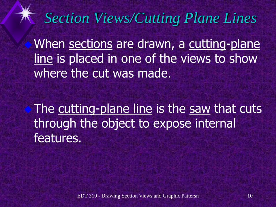
When sections are drawn, a cutting-plane line is placed in one of the views to show where the cut was made.
The cutting-plane line is the saw that cuts through the object to expose internal features.

EDT 310 - Drawing Section Views and Graphic Pattersn 11
Cutting-Plane “Knife”
EDT 310 - Drawing Section Views and Graphic Pattersn 12
Section Views/Cutting Plane Lines
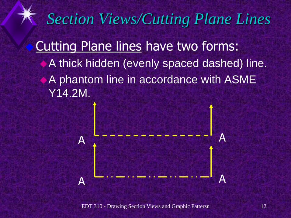
Cutting Plane lines have two forms:
A thick hidden (evenly spaced dashed) line.
A phantom line in accordance with ASME
Y14.2M.
A A
A A

EDT 310 - Drawing Section Views and Graphic Pattersn 13
Section Views/Cutting Plane Lines
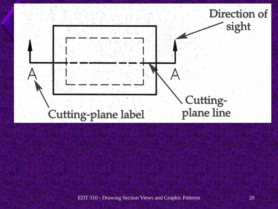
The arrows on the cutting-plane line indicate the direction of sight when looking at the section view.
A A

EDT 310 - Drawing Section Views and Graphic Pattersn 14
Section Views/Cutting Plane Lines
The cutting-plane lines are labeled with letters that relate to the proper section view.
The section name, SECTION A-A, is placed under the view.
EDT 310 - Drawing Section Views and Graphic Pattersn 15
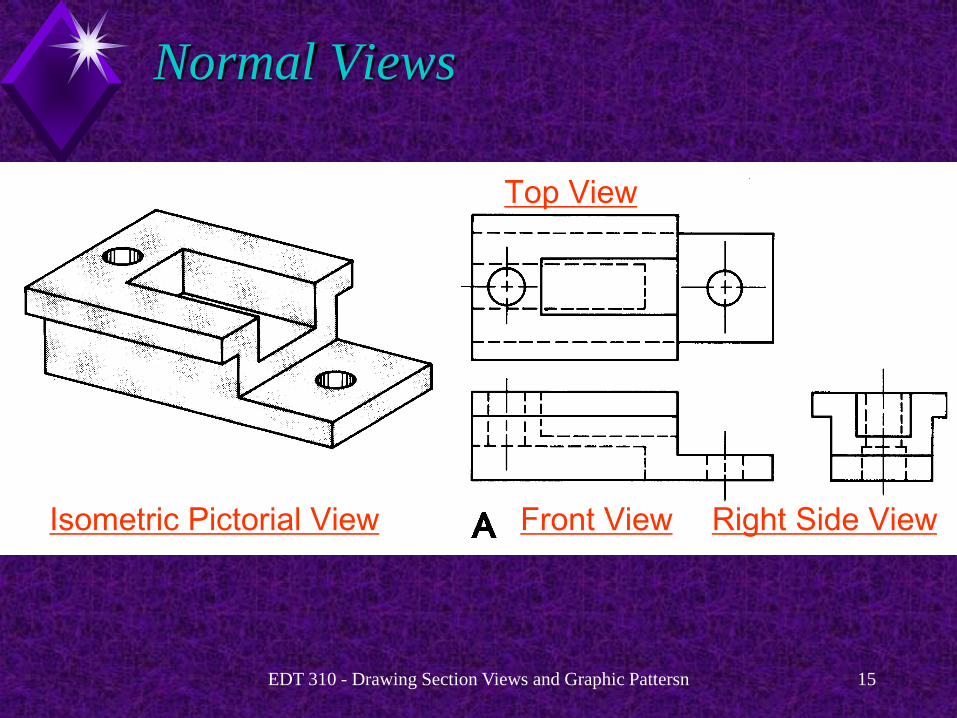
Normal Views
Top View
Front View Right Side View Isometric Pictorial View

EDT 310 - Drawing Section Views and Graphic Pattersn 16
Cutting-Plane
Section View

EDT 310 - Drawing Section Views and Graphic Pattersn 17
Section Views/Cutting Plane Lines
The arrows on the cutting-plane line indicate the line of sight when looking at the section view.
Section A-A

EDT 310 - Drawing Section Views and Graphic Pattersn 18
Section Views/Cutting Plane Lines
The cutting-plane lines are labeled with letters that relate to the proper section view.
SECTION A-A, is placed under the view.
Section A-A
A A

EDT 310 - Drawing Section Views and Graphic Pattersn 19
Section Views/Cutting Plane Lines
When more than one section view is drawn, labels continue with B-B through Z-Z.
EDT 310 - Drawing Section Views and Graphic Pattersn 20

EDT 310 - Drawing Section Views and Graphic Pattersn 21

EDT 310 - Drawing Section Views and Graphic Pattersn 22
Section Line Rules
EDT 310 - Drawing Section Views and Graphic Pattersn 23
Section Line Rules
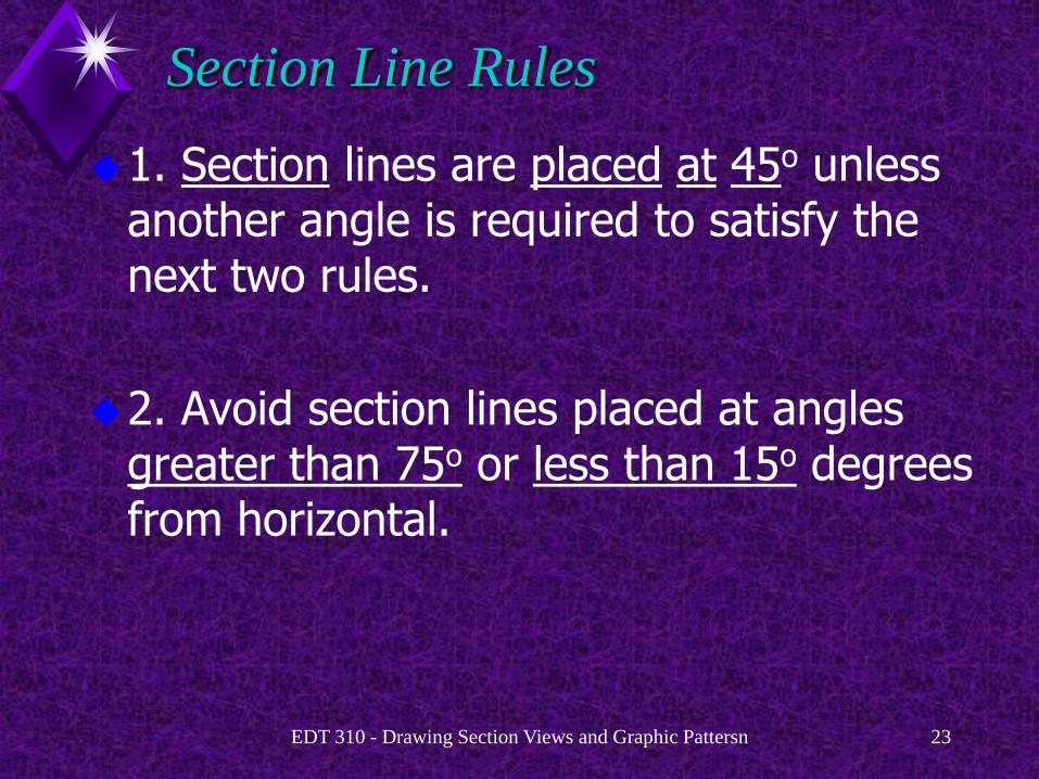
1. Section lines are placed at 45o unless another angle is required to satisfy the next two rules.
2. Avoid section lines placed at angles greater than 75o or less than 15o degrees from horizontal.
EDT 310 - Drawing Section Views and Graphic Pattersn 24
Section Line Rules
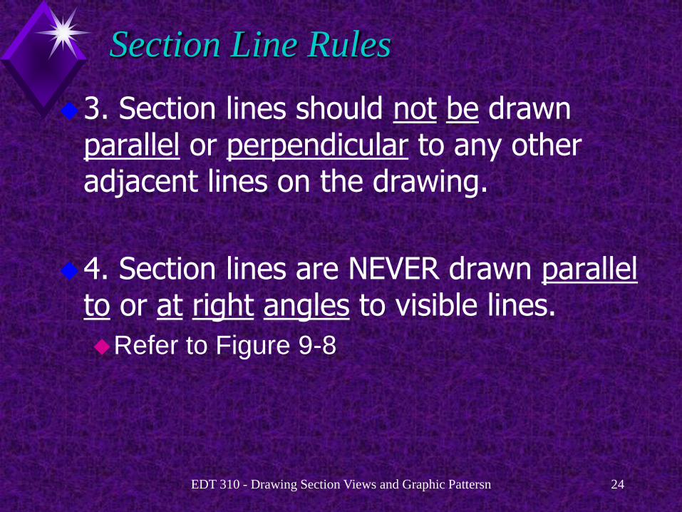
3. Section lines should not be drawn parallel or perpendicular to any other adjacent lines on the drawing.
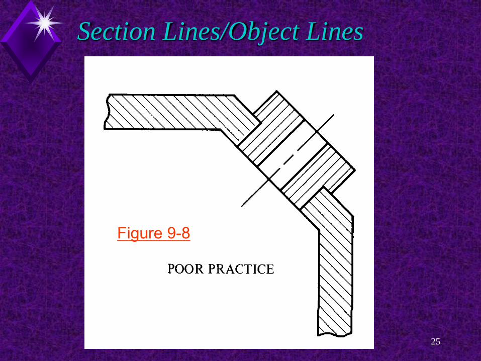
4. Section lines are NEVER drawn parallel to or at right angles to visible lines.
Refer to Figure 9-8
EDT 310 - Drawing Section Views and Graphic Pattersn 25
Figure 9-8
Section Lines/Object Lines

EDT 310 - Drawing Section Views and Graphic Pattersn 26
Section Lines/Object Lines
Figure 9-8

EDT 310 - Drawing Section Views and Graphic Pattersn 27
Section Lines/Object Lines
Figure 9-8

EDT 310 - Drawing Section Views and Graphic Pattersn 28
Section Line Rules
3. Section lines should not cross object lines.
EDT 310 - Drawing Section Views and Graphic Pattersn 29
Types of Sectional Views

EDT 310 - Drawing Section Views and Graphic Pattersn 30
Types of Sectional Views
Types of Sections:
Full Sections.
Offset Sections.
Half Sections.
Broken-Out Sections.
Revolved Sections.
Removed Sections.
Auxiliary Sections.
Phantom (Hidden) Sections.
EDT 310 - Drawing Section Views and Graphic Pattersn 31
Full Sections
EDT 310 - Drawing Section Views and Graphic Pattersn 32
Full Sections
A full section is a sectional view that shows an object as if it were cut completely apart from one end or side to the other.
Full sections remove half the object.
In full sections, the cutting-plane line passes completely through the object along a center plane.

EDT 310 - Drawing Section Views and Graphic Pattersn 33
Full Sections
These views are sometimes just called sections.

EDT 310 - Drawing Section Views and Graphic Pattersn 34
Front View

EDT 310 - Drawing Section Views and Graphic Pattersn 35
Full Section
EDT 310 - Drawing Section Views and Graphic Pattersn 36
Full Sections
The two most common types of full sections are
vertical and
profile sections.
Refer to Figures 9-17 and 9-18.

EDT 310 - Drawing Section Views and Graphic Pattersn 37
Vertical Section

EDT 310 - Drawing Section Views and Graphic Pattersn 38
Profile Section
EDT 310 - Drawing Section Views and Graphic Pattersn 39
Sectioning
Sectioning is also used in other drafting fields, such as architectural and structural drafting.
Cross sections through buildings show the construction methods and materials.

EDT 310 - Drawing Section Views and Graphic Pattersn 40

EDT 310 - Drawing Section Views and Graphic Pattersn 41
EDT 310 - Drawing Section Views and Graphic Pattersn 42
Offset Sections
EDT 310 - Drawing Section Views and Graphic Pattersn 43
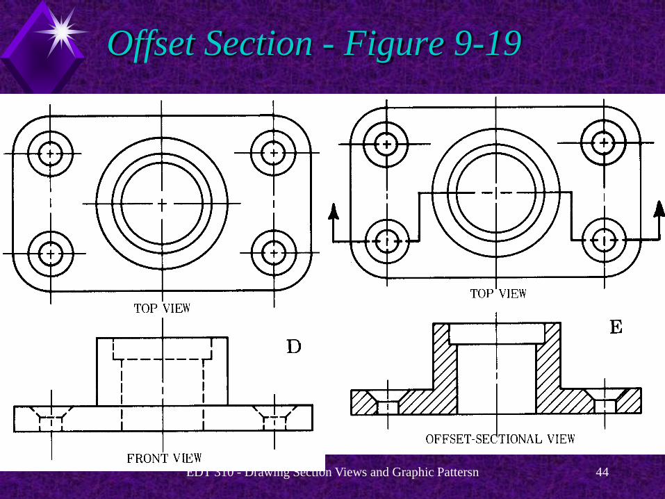
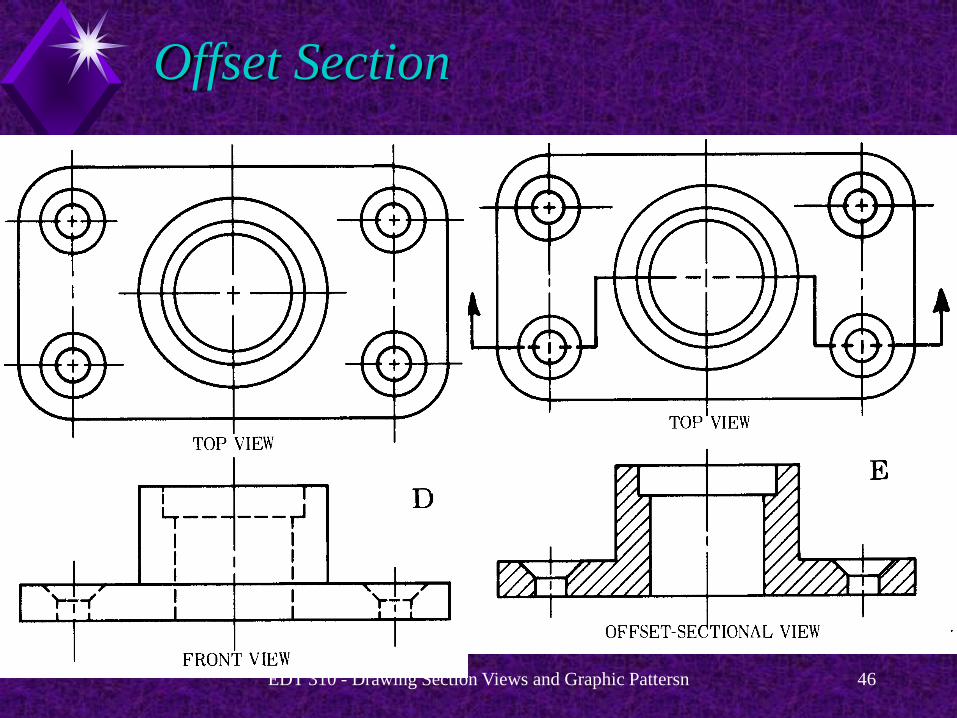
Offset Sections
Offset sections are almost the same as full sections,
Difference: the cutting-plane line is staggered.
The line cuts through features that are not in a straight line.
EDT 310 - Drawing Section Views and Graphic Pattersn 44
Offset Section - Figure 9-19

EDT 310 - Drawing Section Views and Graphic Pattersn 45
EDT 310 - Drawing Section Views and Graphic Pattersn 46
Offset Section

EDT 310 - Drawing Section Views and Graphic Pattersn 47
Half Sections

EDT 310 - Drawing Section Views and Graphic Pattersn 48
Half Sections
A half section is one half of a full section.
Half sections show one-quarter of the object removed.
The term half section is used because
Half of the view appears in section.
The other half is shown as an exterior view.

EDT 310 - Drawing Section Views and Graphic Pattersn 49
Half Section

EDT 310 - Drawing Section Views and Graphic Pattersn 50
Half Sections
Half sections are commonly used on symmetrical objects.
Both the inside and outside can be shown in one view.
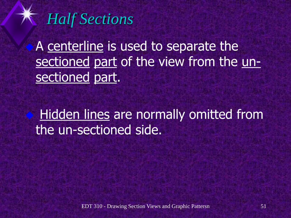
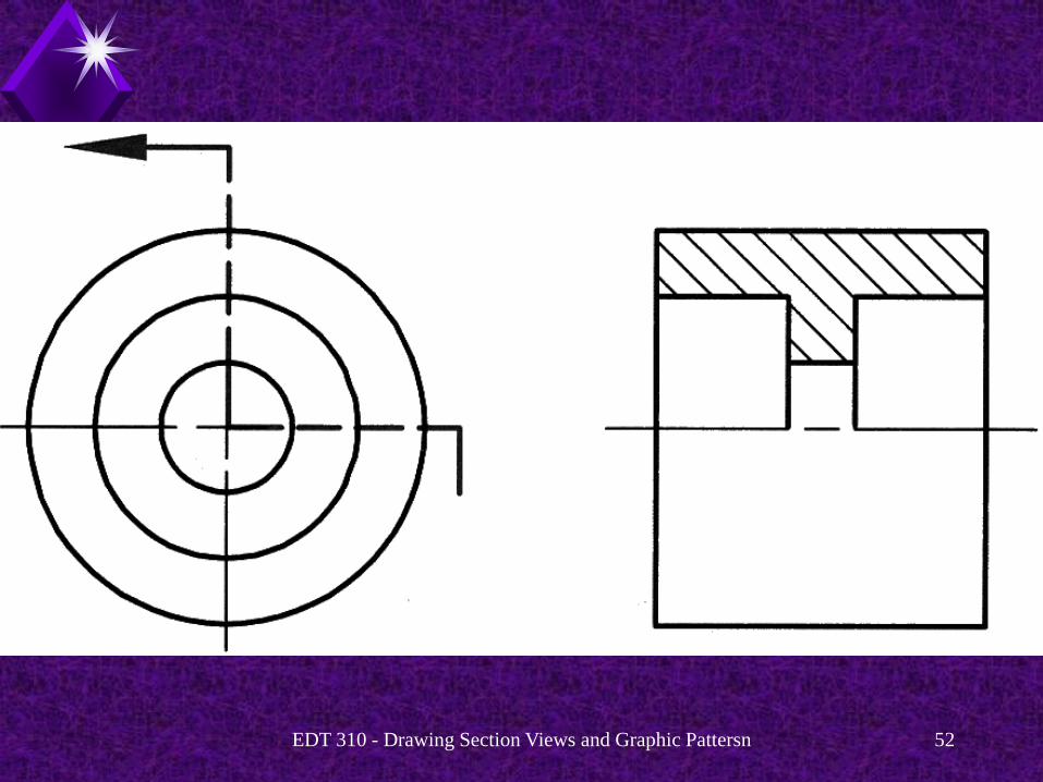
EDT 310 - Drawing Section Views and Graphic Pattersn 51
Half Sections
A centerline is used to separate the sectioned part of the view from the un-sectioned part.
Hidden lines are normally omitted from the un-sectioned side.
EDT 310 - Drawing Section Views and Graphic Pattersn 52
EDT 310 - Drawing Section Views and Graphic Pattersn 53
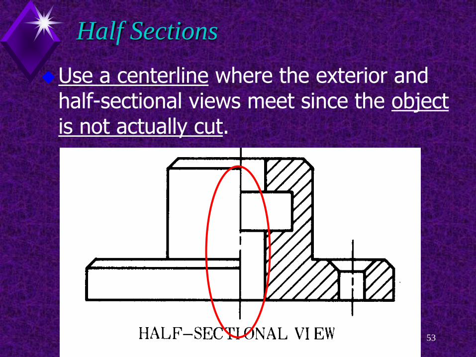
Half Sections
Use a centerline where the exterior and half-sectional views meet since the object is not actually cut.

EDT 310 - Drawing Section Views and Graphic Pattersn 54
Half Sections
In the top view, show the complete object, since no part is actually removed.
Use one arrow for the direction of viewing.

EDT 310 - Drawing Section Views and Graphic Pattersn 55
Half Sections

EDT 310 - Drawing Section Views and Graphic Pattersn 56
Broken Sections

EDT 310 - Drawing Section Views and Graphic Pattersn 57
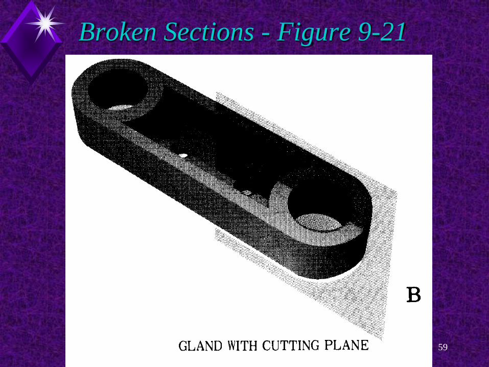
Broken Sections
A broken-out section shows an object as it would look if a portion of it were cut partly away from the rest by a cutting-plane and then “broken off” to reveal the cut surface and insides.
Refer to Figure 9-21

EDT 310 - Drawing Section Views and Graphic Pattersn 58
Broken Sections - Figure 9-21
EDT 310 - Drawing Section Views and Graphic Pattersn 59
Broken Sections - Figure 9-21

EDT 310 - Drawing Section Views and Graphic Pattersn 60
Broken Sections - Figure 9-21

EDT 310 - Drawing Section Views and Graphic Pattersn 61
Broken Sections
A broken-out section show some inside detail without drawing a full or half-section.
EDT 310 - Drawing Section Views and Graphic Pattersn 62
Broken Sections
The broken-out section is bounded by a short-break line drawn freehand the same thickness as visible lines.
Refer to Figure 9-22
EDT 310 - Drawing Section Views and Graphic Pattersn 63
Broken-out Sections
Broken-out sections show only a small portion of the object removed.
Broken-out sections clarify hidden features.

EDT 310 - Drawing Section Views and Graphic Pattersn 64
Broken Sections - Figure 9-21

EDT 310 - Drawing Section Views and Graphic Pattersn 65
Broken Sections - Figure 9-21

EDT 310 - Drawing Section Views and Graphic Pattersn 66
Broken Sections - Figure 9-21

EDT 310 - Drawing Section Views and Graphic Pattersn 67
Broken Sections - Figure 9-21

EDT 310 - Drawing Section Views and Graphic Pattersn 68
Aligned Sections

EDT 310 - Drawing Section Views and Graphic Pattersn 69
Aligned Sections
Aligned sections are used when a feature is out of alignment with the center plane.
An offset section will distort the image.

EDT 310 - Drawing Section Views and Graphic Pattersn 70
Aligned Sections
The cutting-plane line cuts through the feature to be sectioned.
The feature is then rotated to align with the center plane before projecting into the section view.

EDT 310 - Drawing Section Views and Graphic Pattersn 71

EDT 310 - Drawing Section Views and Graphic Pattersn 72
Revolved Sections

EDT 310 - Drawing Section Views and Graphic Pattersn 73
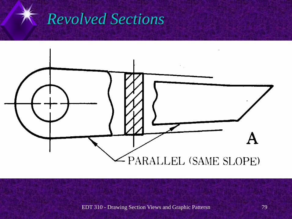
Revolved Sections
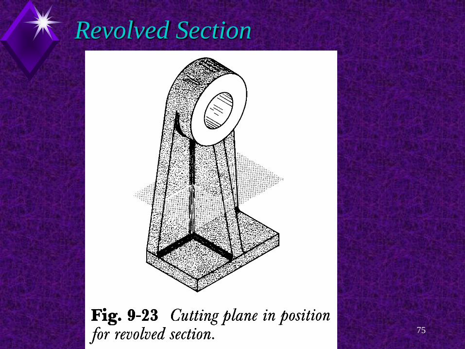
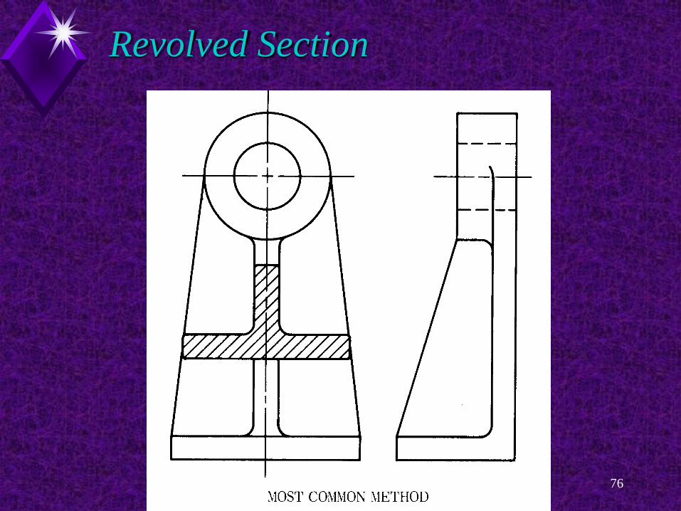
Revolved sections clarify the contour of objects that have the same shape throughout their length.
The section is revolved in place within the object, or part of the view may be broken away.

EDT 310 - Drawing Section Views and Graphic Pattersn 74
Revolved Sections
Use a revolved section:
When the part is long and thin.
When its shape in cross section is the same
throughout.
EDT 310 - Drawing Section Views and Graphic Pattersn 75
Revolved Section
EDT 310 - Drawing Section Views and Graphic Pattersn 76
Revolved Section

EDT 310 - Drawing Section Views and Graphic Pattersn 77
Revolved Section
EDT 310 - Drawing Section Views and Graphic Pattersn 78
Revolved Section
The view may be shortened.
Give the full-length of the part by a dimension.
This lets you draw a large part with a revolved section in a short space.
EDT 310 - Drawing Section Views and Graphic Pattersn 79
Revolved Sections

EDT 310 - Drawing Section Views and Graphic Pattersn 80
Revolved Sections

EDT 310 - Drawing Section Views and Graphic Pattersn 81

EDT 310 - Drawing Section Views and Graphic Pattersn 82
Removed Sections
EDT 310 - Drawing Section Views and Graphic Pattersn 83
Removed Sections
Removed sections serve much the same function as revolved sections.
The section view is removed from the regular view and moved somewhere else on the drawing sheet.

EDT 310 - Drawing Section Views and Graphic Pattersn 84
Removed Sections
A removed section is taken from its normal place on the view and moved somewhere else on the drawing sheet.
A cutting-plane line shows where the section was taken.

EDT 310 - Drawing Section Views and Graphic Pattersn 85
Removed Sections
When multiple removed sections are taken, the cutting planes and related views are labeled.
Drawing only the ends of the cutting-plane lines simplifies the views.

EDT 310 - Drawing Section Views and Graphic Pattersn 86
Removed Sections
The removed section must be positioned to look as if it were in its normal place on the view.
The removed section cannot be rotated in just any direction !
Refer to Figure 9-26 for examples
EDT 310 - Drawing Section Views and Graphic Pattersn 87
Removed Sections
When multiple removed sections are taken, the cutting planes and related views are labeled.
Drawing only the ends of the cutting-plane lines simplifies the views.

EDT 310 - Drawing Section Views and Graphic Pattersn 88

EDT 310 - Drawing Section Views and Graphic Pattersn 89

EDT 310 - Drawing Section Views and Graphic Pattersn 90
Removed Sections

EDT 310 - Drawing Section Views and Graphic Pattersn 91
Removed Sections

EDT 310 - Drawing Section Views and Graphic Pattersn 92
Removed Sections
EDT 310 - Drawing Section Views and Graphic Pattersn 93
Auxiliary Sections
EDT 310 - Drawing Section Views and Graphic Pattersn 94
Auxiliary Sections
An auxiliary section is a view which is produced when a cutting plane line passes through an object at an angle.
Refer to Figure 9-27A
An auxiliary section is drawn like any other auxiliary view.

EDT 310 - Drawing Section Views and Graphic Pattersn 95
Auxiliary Sections Figure 9-27

EDT 310 - Drawing Section Views and Graphic Pattersn 96
Auxiliary Sections Figure 9-27
EDT 310 - Drawing Section Views and Graphic Pattersn 97
Phantom (Hidden) Sections

EDT 310 - Drawing Section Views and Graphic Pattersn 98
Phantom (Hidden) Sections
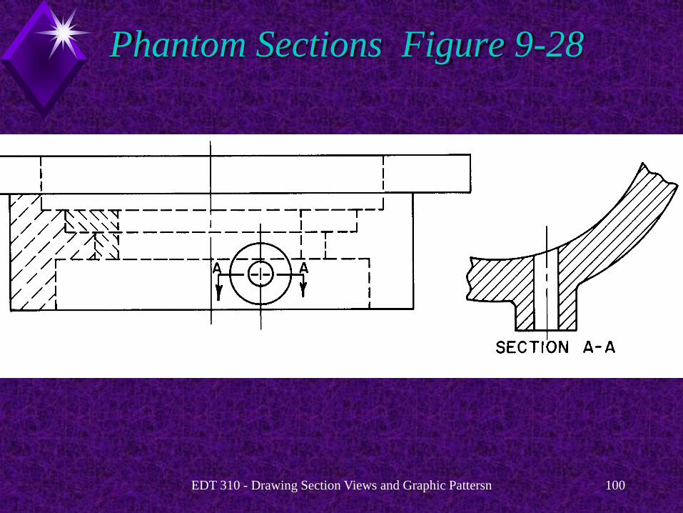
A phantom section is used to show one view both of the inside and outside of an object that is not completely symmetrical.

EDT 310 - Drawing Section Views and Graphic Pattersn 99
Phantom (Hidden) Sections
Since the object is not symmetrical, the inside cannot be shown with a half section.
A phantom section is used instead.
Refer to Figure 9-28.
EDT 310 - Drawing Section Views and Graphic Pattersn 100
Phantom Sections Figure 9-28
EDT 310 - Drawing Section Views and Graphic Pattersn 101
Drawing Section Lines
and
Hatch Patterns with AutoCAD
EDT 310 - Drawing Section Views and Graphic Pattersn 102
Section Lines/Hatch Patterns
The BHATCH (BH) command
Automatically hatches any enclosed area.
Steps
1. BH
2. Select Hatch patterns
3. Select enclosed area
EDT 310 - Drawing Section Views and Graphic Pattersn 103
Section Lines/Hatch Patterns
The BHATCH command:
Pick the Hatch button on the Draw toolbar
Pick Hatch... in the Draw pull-down menu,
Enter H, BH, or BHATCH at the Command:
prompt.
EDT 310 - Drawing Section Views and Graphic Pattersn 104
EDT 310 - Drawing Section Views and Graphic Pattersn 105

EDT 310 - Drawing Section Views and Graphic Pattersn 106
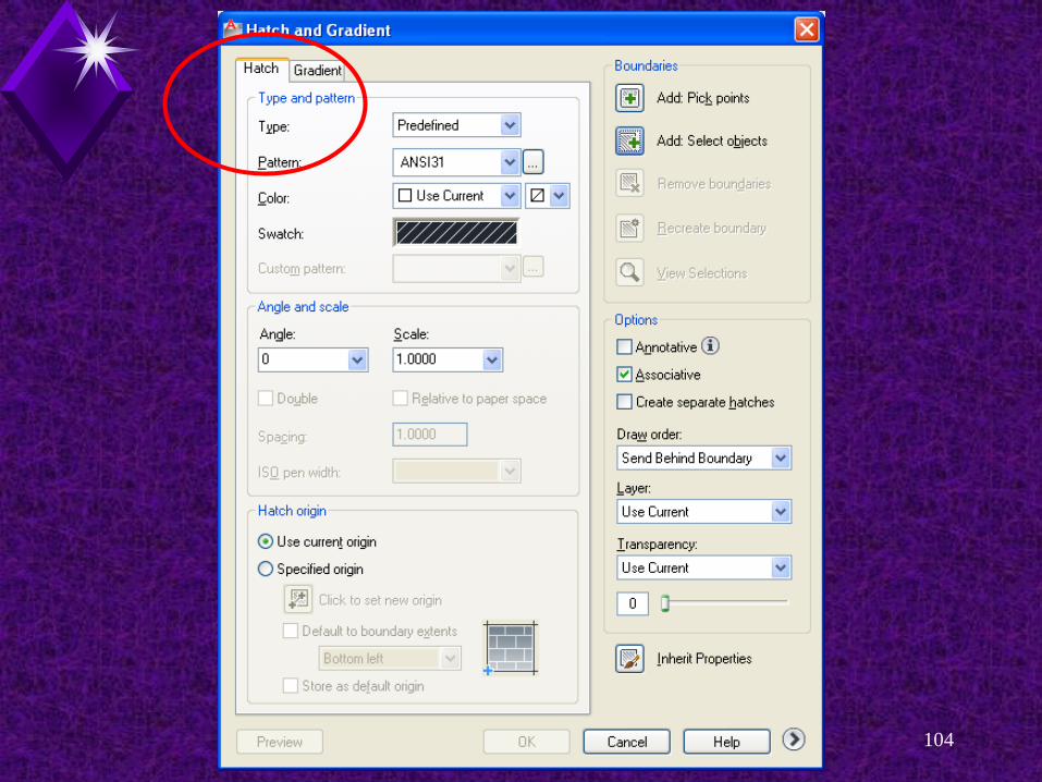
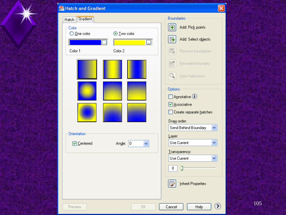
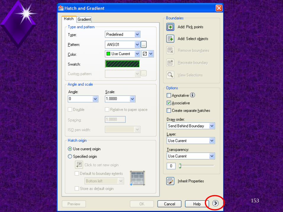
Hatch and Gradient
Boundary Hatch dialog box
Hatch tab
Gradient tab
Buttons
Add: Pick points
Add: Select objects
Inherit properties.
Hatch and Gradient
Type and Pattern
Type
Predefined
User defined
Custom
Pattern
ANSI
ISO
Other Predefined
Custom
EDT 310 - Drawing Section Views and Graphic Pattersn 107
Hatch and Gradient
Options
Angle
“AutoCAD math” 0 = 45°
Scale
0.2500 - 2.000
Hatch origin
Use current origin
Specify origin
EDT 310 - Drawing Section Views and Graphic Pattersn 108
Hatch and Gradient
Options
Annotative
Associative
Create separate hatches
Draw Order
Do not assign
Send to back
Bring to front
Bring in front of boundary
EDT 310 - Drawing Section Views and Graphic Pattersn 109
Hatch and Gradient
Options
Layer
Use Current
0
Transparency
Use Current
ByLayer
ByBlock
Specify value
EDT 310 - Drawing Section Views and Graphic Pattersn 110

EDT 310 - Drawing Section Views and Graphic Pattersn 111
Selecting a Hatch Pattern
Select the hatch pattern
Three categories of hatch patterns are available:
Predefined.
User defined.
Custom.
EDT 310 - Drawing Section Views and Graphic Pattersn 112
Selecting a Hatch Pattern
Predefined Patterns:
These predefined AutoCAD patterns are
stored in the acad.pat and acadiso.pat files.
User defined Patterns.
Selecting this option creates a pattern of lines
based on the current linetype in your drawing.
You can control the angle and spacing of the
lines.

EDT 310 - Drawing Section Views and Graphic Pattersn 113
Selecting a Hatch Pattern
Custom Patterns:
Specifies a pattern that is defined in any
custom .PAT File that you have added to the
AutoCAD search path.
Choose Predefined to use the patterns in the
supplied acad.pat and acadiso.pat files.

EDT 310 - Drawing Section Views and Graphic Pattersn 114
Hatch Patterns

EDT 310 - Drawing Section Views and Graphic Pattersn 115
AutoCAD Hatch Patterns
AutoCAD has standard section line symbols available, called hatch patterns.
These symbols are located in the acad.pat file.
EDT 310 - Drawing Section Views and Graphic Pattersn 116
AutoCAD Hatch Patterns
When very thin objects are sectioned, the material may be completely filled in.
AutoCAD refers to this as solid.

EDT 310 - Drawing Section Views and Graphic Pattersn 117
AutoCAD Hatch Patterns
When you change to a different hatch pattern, the new pattern becomes the default in the current drawing until it is changed.

EDT 310 - Drawing Section Views and Graphic Pattersn 118
Predefined Hatch Patterns

EDT 310 - Drawing Section Views and Graphic Pattersn 119
Predefined Hatch Patterns
AutoCAD has many predefined hatch patterns.
These patterns are contained in the acad.pat and acadiso.pat files.

EDT 310 - Drawing Section Views and Graphic Pattersn 120
Predefined Hatch Patterns
To select a predefined hatch pattern:
Select Predefined in the Type: drop-down list
Select the predefined pattern from the drop-
down list
OR
Oick the ellipsis (... ) button to display the
Hatch Pattern Palette dialog box.
EDT 310 - Drawing Section Views and Graphic Pattersn 121
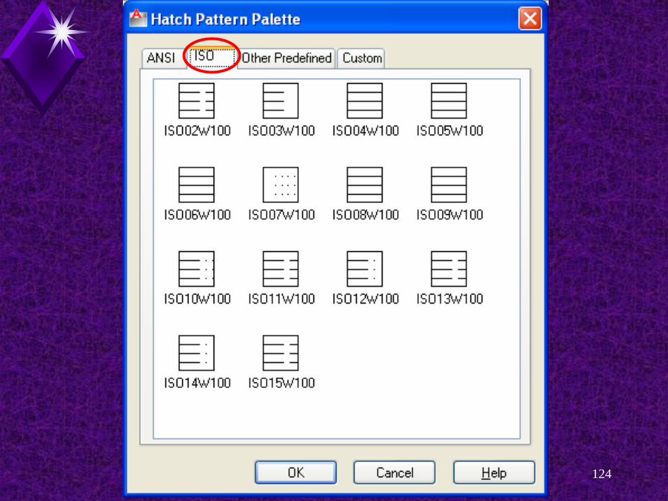
Predefined Hatch Patterns
The Hatch Pattern Palette
Provides sample images of the predefined
hatch patterns.
The hatch patterns are divided among the four tabs:
ANSI
ISO
Other Predefined
Custom.

EDT 310 - Drawing Section Views and Graphic Pattersn 122

EDT 310 - Drawing Section Views and Graphic Pattersn 123
EDT 310 - Drawing Section Views and Graphic Pattersn 124

EDT 310 - Drawing Section Views and Graphic Pattersn 125

EDT 310 - Drawing Section Views and Graphic Pattersn 126

EDT 310 - Drawing Section Views and Graphic Pattersn 127
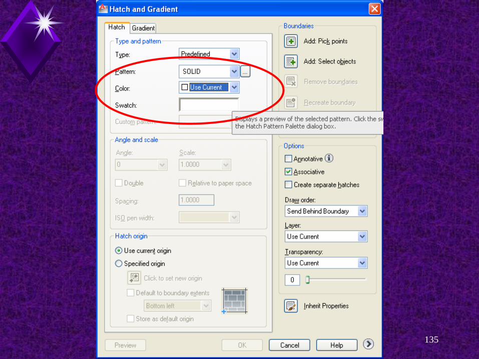
Predefined Hatch Patterns
Select the desired pattern
Pick the OK button to return to the Boundary Hatch dialog box.
The selected pattern is displayed in the
Swatch tile and listed in the Pattern: text box.
You can also access the Hatch Pattern Palette dialog box by picking the image displayed in the Swatch tile.

EDT 310 - Drawing Section Views and Graphic Pattersn 128
EDT 310 - Drawing Section Views and Graphic Pattersn 129
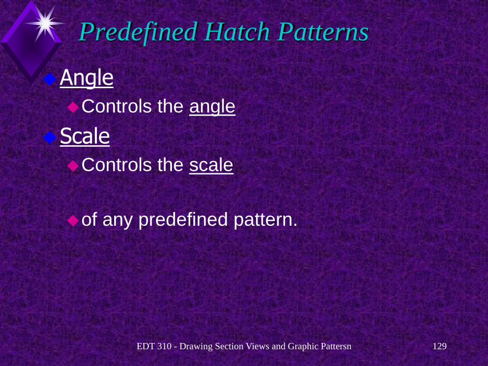
Predefined Hatch Patterns
Angle
Controls the angle
Scale
Controls the scale
of any predefined pattern.

EDT 310 - Drawing Section Views and Graphic Pattersn 130

EDT 310 - Drawing Section Views and Graphic Pattersn 131

EDT 310 - Drawing Section Views and Graphic Pattersn 132
Predefined Hatch Patterns
For predefined ISO patterns (only), you can also control the ISO pen width using the ISO pen width: drop-down list.

EDT 310 - Drawing Section Views and Graphic Pattersn 133

EDT 310 - Drawing Section Views and Graphic Pattersn 134
Predefined Hatch Patterns
An object can be hatched solid by selecting the SOLID predefined pattern.
EDT 310 - Drawing Section Views and Graphic Pattersn 135

EDT 310 - Drawing Section Views and Graphic Pattersn 136
Hatch Pattern Scale
EDT 310 - Drawing Section Views and Graphic Pattersn 137
Hatch Pattern Scale
Scale hatch patterns can be scaled
Use the Scale: text box.
Common scales, broken down in 0.25
increments.
Range: 0.25 to 2.
You can type any scale in the text box.
AutoCAD stores the selected scale in the
HPSCALE system variable.
Default = 1
EDT 310 - Drawing Section Views and Graphic Pattersn 138
Hatch Pattern Scale
Relative to paper space check box
Scales hatch pattern relative to paper space
units.
Wizards set the hatch pattern scale factor automatically based on the information you provide.
Settings are related to the full scale of the
objects you draw.
EDT 310 - Drawing Section Views and Graphic Pattersn 139
Hatch Pattern Scale
Use a larger scale factor when hatching large areas.
This makes your section lines look neater and
saves regeneration time.
EDT 310 - Drawing Section Views and Graphic Pattersn 140
Selecting Areas To Be Hatched

EDT 310 - Drawing Section Views and Graphic Pattersn 141
Selecting Areas to Be Hatched
Select areas to be hatched by one of two methods:
Pick points Button.
Select objects Button.

EDT 310 - Drawing Section Views and Graphic Pattersn 142
EDT 310 - Drawing Section Views and Graphic Pattersn 143
Selecting Areas to Be Hatched
Pick Points button
Easiest method to hatch an area.
Pick the button.
The drawing returns.
Pick a point within the region to be hatched
AutoCAD automatically defines the boundary
around the selected point.

EDT 310 - Drawing Section Views and Graphic Pattersn 144
Selecting Areas to Be Hatched
The following prompts are displayed:
Select internal point: (pick a point inside the
area to be hatched)
Selecting everything visible...
Analyzing the selected data...
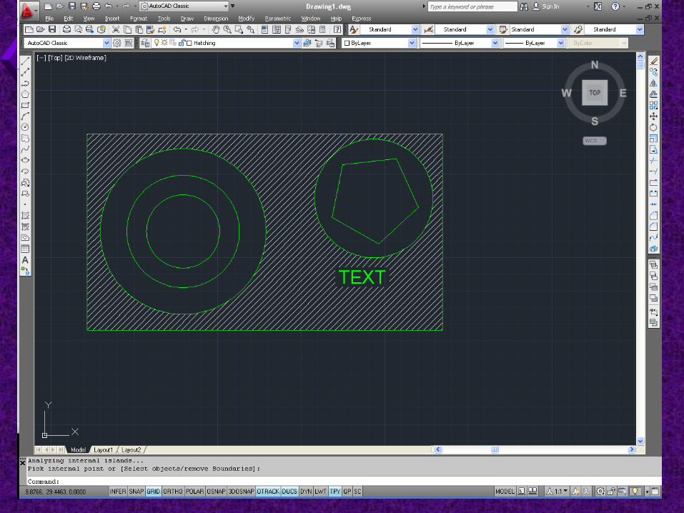
Analyzing internal islands...
Select internal point: (pick an internal point of
another object or [Enter] if you are done
selecting objects)

EDT 310 - Drawing Section Views and Graphic Pattersn 145
Selecting Areas to Be Hatched
More than one internal point can be selected.
When you are finished selecting points,
Press [Enter]
The Boundary Hatch dialog box returns
Pick the OK button
The feature is automatically hatched.

EDT 310 - Drawing Section Views and Graphic Pattersn 146
EDT 310 - Drawing Section Views and Graphic Pattersn 147
Selecting Areas to Be Hatched
Enter U or UNDO to undo the last selection, in case you picked the wrong area.
Undo the hatch pattern by entering U at the
Command: prompt after the pattern is drawn.
Preview the hatch before applying it to save time.
EDT 310 - Drawing Section Views and Graphic Pattersn 148
Selecting Areas to Be Hatched
Use the Select Objects button to define the hatch boundary if you have items that you want to hatch by picking the object, rather than picking inside the object.

EDT 310 - Drawing Section Views and Graphic Pattersn 149
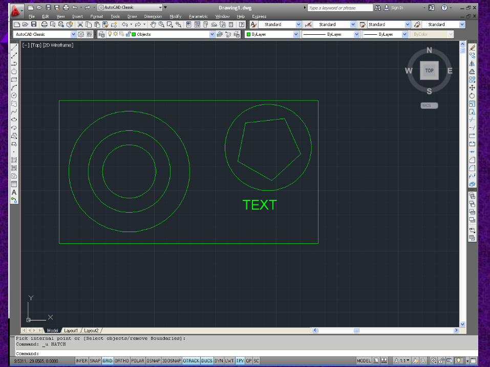
Selecting Areas to Be Hatched
Objects
Circles
Polygons
Closed polylines
The Select Objects button can also be used to pick an object inside an area to be hatched to exclude it from the hatch pattern.
Selecting Areas to Be Hatched
Open Boundary
AutoCAD will hatch an open boundary
Results may not be what is desired
EDT 310 - Drawing Section Views and Graphic Pattersn 150
EDT 310 - Drawing Section Views and Graphic Pattersn 151
EDT 310 - Drawing Section Views and Graphic Pattersn 152
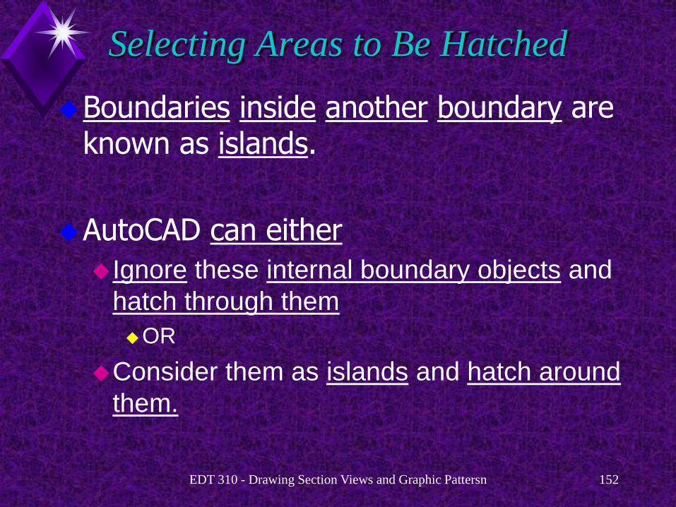
Selecting Areas to Be Hatched
Boundaries inside another boundary are known as islands.
AutoCAD can either
Ignore these internal boundary objects and
hatch through them
OR
Consider them as islands and hatch around
them.
EDT 310 - Drawing Section Views and Graphic Pattersn 153

EDT 310 - Drawing Section Views and Graphic Pattersn 154

EDT 310 - Drawing Section Views and Graphic Pattersn 155
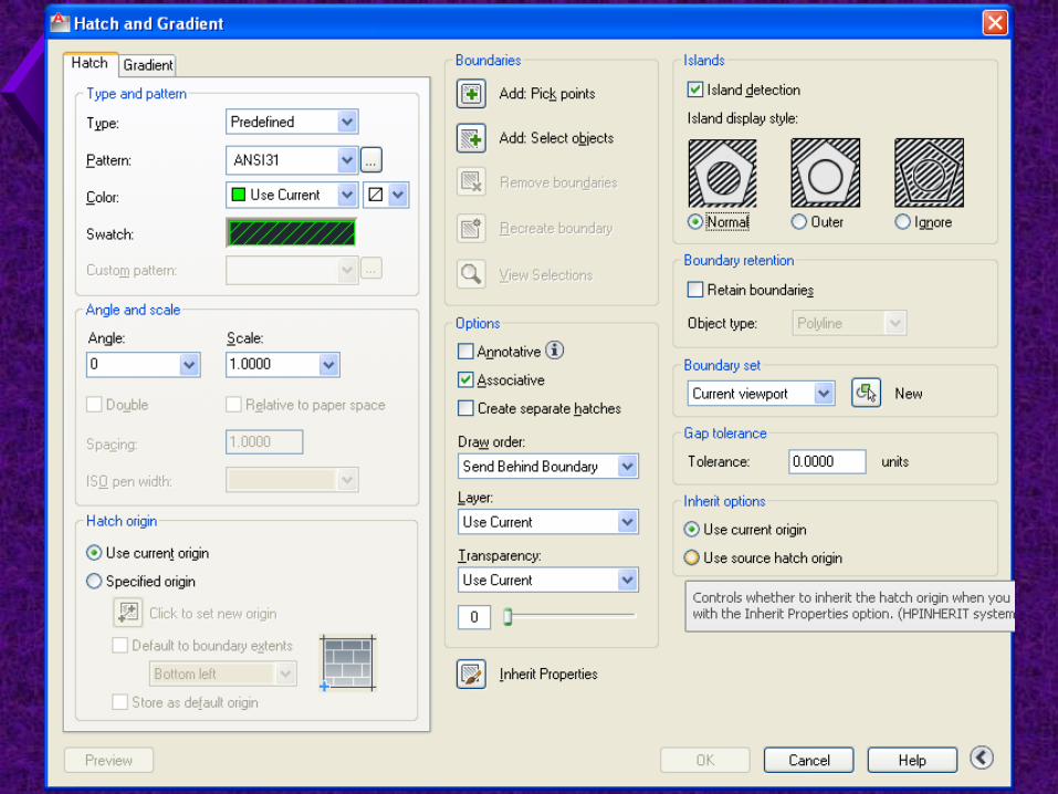
Selecting Areas to Be Hatched
Normal.
Hatches inward from the outer boundary.
If AutoCAD encounters an island, it turns off
hatching until it encounters another island,
then hatching is reactivated.
Every other closed boundary is hatched with this option.
EDT 310 - Drawing Section Views and Graphic Pattersn 156
EDT 310 - Drawing Section Views and Graphic Pattersn 157

EDT 310 - Drawing Section Views and Graphic Pattersn 158

EDT 310 - Drawing Section Views and Graphic Pattersn 159
Selecting Areas to Be Hatched
Outer.
Hatches inward from the outer boundary.
AutoCAD turns hatching off when it
encounters an island and DOES NOT turn it
back on.
AutoCAD hatches only the outermost level of
the structure and leaves the internal structure
blank.

EDT 310 - Drawing Section Views and Graphic Pattersn 160

EDT 310 - Drawing Section Views and Graphic Pattersn 161
EDT 310 - Drawing Section Views and Graphic Pattersn 162

EDT 310 - Drawing Section Views and Graphic Pattersn 163
Selecting Areas to Be Hatched
Ignore.
Ignores ALL islands
HATCHES EVERYTHING within the selected
boundary.

EDT 310 - Drawing Section Views and Graphic Pattersn 164

EDT 310 - Drawing Section Views and Graphic Pattersn 165

EDT 310 - Drawing Section Views and Graphic Pattersn 166
Hatch Pattern Composition
The BHATCH command creates associative hatch patterns by default
It can be set to create non-associative patterns.
EDT 310 - Drawing Section Views and Graphic Pattersn 167
Hatch Pattern Composition
Associative Hatch Patterns
Update automatically when the boundary is
edited.
Automatically fill the new area with the original
hatch pattern If the boundary is stretched,
scaled, or otherwise edited.

EDT 310 - Drawing Section Views and Graphic Pattersn 168
Hatch Pattern Composition
Non-associative hatch
Is independent of its boundaries.
The hatch pattern DOES NOT CHANGE with
the hatch boundary.
You must select both the boundary and the
pattern before editing if you want to modify
both.

EDT 310 - Drawing Section Views and Graphic Pattersn 169
Correcting Errors in the Boundary
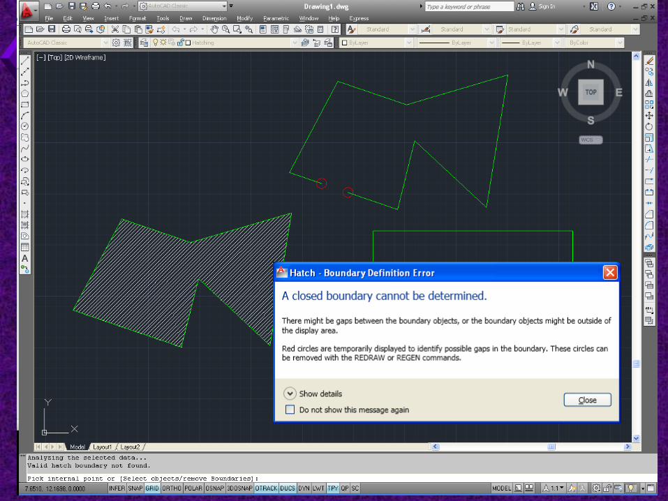
BHATCH works well unless you have an error in the hatch boundary.
The most common error is a gap in the boundary.
This can be very small and difficult to detect
Occurs when you do not close the geometry
or use object snaps for accuracy.

EDT 310 - Drawing Section Views and Graphic Pattersn 170
Correcting Errors in the Boundary
Picking a point outside the boundary area
Creates a Boundary Definition Error alert.
Pick OK.
Select a point inside the boundary you want hatched.

EDT 310 - Drawing Section Views and Graphic Pattersn 171
Hatching Tips

EDT 310 - Drawing Section Views and Graphic Pattersn 172
Hatching Tips
1. Zoom in on the area to be hatched
It make it easier for you to define the
boundary.
The hatch process is much faster because
AutoCAD does not have to search the entire
drawing to find the hatch boundaries.

EDT 310 - Drawing Section Views and Graphic Pattersn 173
Hatching Tips
2. Preview the hatch before you apply it. This allows you to easily make last minute
adjustments.
3. Turn off layers where there are lines or text that might interfere with your ability to accurately define hatch boundaries.
4. Create boundary sets of small areas within a complex drawing to help save time.

EDT 310 - Drawing Section Views and Graphic Pattersn 174
Hatching around Text
EDT 310 - Drawing Section Views and Graphic Pattersn 175
Hatching around Text
AutoCAD automatically places an imaginary box around the text in a hatch boundary.
Hatch patterns are not placed inside these
imaginary boxes.
Always place the text before hatching the area.
EDT 310 - Drawing Section Views and Graphic Pattersn 176
Editing Hatch Patterns

EDT 310 - Drawing Section Views and Graphic Pattersn 177
Editing Hatch Patterns
Edit hatch boundaries and hatch patterns with grips and editing commands such as ERASE, COPY, MOVE, ROTATE, and SCALE.

EDT 310 - Drawing Section Views and Graphic Pattersn 178
Editing Hatch Patterns
Access the HATCHEDIT command by:
Picking Hatch... in the Modity pull-down menu
OR
Picking the Edit Hatch button on the Modify II
toolbar
OR
Entering HE or HATCHEDIT at the Command:
prompt.

EDT 310 - Drawing Section Views and Graphic Pattersn 179
Editing Hatch Patterns
HATCHEDIT
Works just like original hatching
Make edits as desired

EDT 310 - Drawing Section Views and Graphic Pattersn 180
Editing Hatch Patterns
You can
Change the pattern type, scale, or angle;
Remove the associative qualities;
Set the inherit properties of an existing hatch
pattern;
Use the Advanced tab options to edit the
hatch pattern.
Preview the edited hatch before applying it to
your drawing.