draft provisional specification for composite … · page 1 of 15 draft provisional specification...
TRANSCRIPT

Page 1 of 15
DRAFT PROVISIONAL SPECIFICATION FOR COMPOSITE SLEEPER
1.0 SCOPE
This specification is intended to provide guidelines for design, manufacture and use of engineered composite sleepers and their components primarily for but not limited to girder bridges on Indian Railway track system. The specification contains minimum performance requirement for engineered composite sleepers.
The specification covers physical dimensions, physical properties and structural strength of engineered composite sleepers. The specification does not cover material and techniques or equipments for manufacture of engineered composite sleepers.
Engineered composite sleepers are a relatively new technology compared to the more conventional sawn wood, concrete or steel sleepers. These specifications have been prepared based on the laboratory testing done so far on sleepers obtained by Indian Railways (IR)/ Research Designs & Standards Organisation (RDSO) for trial purposes; relevant provisions contained in the specifications or recommended practices of other technical bodies, such as American Society for Testing and Material (ASTM), American Railway Engineering and Maintenance-of-Way Association (AREMA), Chicago Transit Authority (CTA), Union Pacific Railroad (UPRR), etc. and limited experience obtained from trial of one particular type of sleeper on Indian Railways.
Therefore, this specification would primarily serve the purpose to procure more of such sleepers for conducting field trials on Indian Railways (IR). This specification, therefore, may be needed to be revised based on further data generated by future laboratory/field testing; experience from more trials from additional sources; further interaction with industry; etc.
The Composite sleepers may be supplied by an Indian firm having a collaboration/partnership with foreign manufacturer. In such cases, supplier, wherever used in this specification, means Indian firm/partner/representative subject to having a valid MOU (Memorandum of Understanding) or Agreement with the manufacturer.
2.0 TECHNICAL REQUIREMENTS
2.1 MATERIAL REQUIREMENTS
2.1.1 A composite material is a material formed using two or more discretely identified materials (e.g. a polymer binder with reinforcement in polymer composites) to obtain specific properties that are superior to the individual material.
2.1.2 Engineered polymer composite sleeper incorporates a polymer matrix typically post-consumer recycled high-density polyethylene (HDPE) as a primary component, with reinforcing fibres and / or fillers to contribute enhanced properties. Toxic preservatives shall not be used to manufacture the sleeper. The

Page 2 of 15
sleeper shall resist decay and insect attack. Water absorption shall not cause loss of strength requiring the sleeper to be replaced. The sleeper shall be non-hazardous and non-leaching.
2.1.3 In general, composite sleeper is a material system that incorporates reinforcement (e.g. glass fibres) and / or other property modifiers in a polymer matrix. Based on reinforcement and property modifiers, the Polymer composite sleepers may be classified as any one of the following :
a) Fibre reinforced polymer composite- polymer reinforced with fibrous glass or other fibres, including polymeric fibres. Fillers and other modifiers may also be added to enhance particular physical or mechanical properties.
b) Particle reinforced polymer composite- polymer modified with dispersed small particles to enhance particulars physical and / or mechanical properties.
c) Hybrid composite – a composite that incorporates two different reinforcement fibres or other structural components (e.g. a concrete steel and polymer combination).
2.1.4 The composite sleeper is to be developed as per the manufacturer’s specification
to suit the requirements of the Indian Railway system. Therefore, the manufacturer has to specify the type of raw material proposed to be used in manufacturing the product. The source of supply of raw materials, their specifications, testing procedure, quality assurance plan etc., shall have to be specified by the manufacturer along with supporting documents.
2.2 GENERAL REQUIREMENTS
Engineered composite sleepers shall meet the following general requirements:
2.2.1 Sleeper shall permit the use of standard rail, MS bearing plates and holding down fasteners, such as rail screws without requiring special procedures for installation other than ordinary pre-drilling of the sleeper.
2.2.2 Sleeper shall give satisfactory performance under maximum axle load of 25t and shall be able to provide rail seat loading (compression) without failure. Sleeper shall be stiff enough to support the weight but flexible enough to absorb the vibration of passing trains. In effect, its performance in this respect shall be equal to or better than hard wood sleepers, prevalent on Indian Railway system.
2.2.3 Sleeper shall not be prone to failure due to weather-related high heat or freezing temperatures, in all four temperature zones of Indian Railway system.
2.2.4 Sleeper shall not warp or sag to the level of permanent deformation that would require replacement of the sleeper.
2.2.5 Sleeper shall not require end caps. Sleeper shall not split or crack in any way requiring the sleeper to be replaced.
2.2.6 Material surface degradation due to solar ultraviolet (UV) radiation exposure shall not exceed 0.076 mm per year.

Page 3 of 15
2.2.7 It would be preferable if the sleeper is grey or black in color but shall not be red in color. It shall not have any cracks on external surface or splitting marks. Sleepers shall be solid and shall be free from voids in general.
2.2.8 Sleeper shall be fire resistant in prevailing Indian condition and shall be suitable for use in track circuited area. These sleepers shall exhibit aforesaid properties equivalent to or more than those of a wooden sleeper.
2.2.9 The manufacturer shall specify specific gravity of sleepers supplied/used for structural testing. Every sleeper, supplied afterwards, shall conform to the same specific gravity.
2.2.10 The sleeper shall be durable, so as to retain necessary strength and other structural properties during service in track.
2.2.11 The sleeper shall be resistant to rot, bacteria and insects such as termites, borers etc which may reduce strength and/or integrity of sleeper.
2.3. DIMENSIONAL REQUIREMENTS
2.3.1 Before manufacturing sleepers, supplier shall ascertain what sizes shall be accepted. However, the minimum width and depth of sleeper to be used on Steel Girder Bridges should not be less than 250mm and 180mm respectively.
2.3.2 Sleepers, required to be laid on Steel Girder Bridges, shall have all four sides smooth (non-skid). The ends should have neat & smooth vertical surface free of any crack, voids etc.
2.3.3 Sleeper surface flatness in the area of the bearing plate shall be within 3.2 mm
(1/8”).
2.3.4 Sleeper dimensions as specified shall be full size. Sleepers shall have a thickness tolerance +12.7mm (1/2”), -0mm, width tolerance +12.7mm (1/2”), -0mm, length tolerance +50.8mm (2”), -12.7mm (1/2”).
2.3.5 Sleepers will be considered straight when a straight line along each sleeper face from the middle of one end to the middle of the other ends is no closer to the edge of the sleeper than one half the sleeper face dimensions, plus 6.4mm (1/4”) or minus 6.4mm (1/4”).
2.4 PERFORMANCE REQUIREMENTS
2.4.1 Engineered composite sleeper shall meet physical and mechanical performances requirements listed in table given below:
Table- I Physical and Mechanical Properties
Mechanical Properties/Test Method Typical Value
Modulus of Elasticity (Compression) 1170 MPa (min.)
Rail seat compression 6.2 MPa (min.)
Modulus of Rupture 13.8 MPa (min.)

Page 4 of 15
Screw Spike Withdrawal (Spikes to drawing 22.2 KN (min.) No. SF-1 of IRS Track Manual)
Coefficient of Thermal Expansion 1.35 X 10⁻⁴ /oC (max.)
Aging (Laboratory) 75% of physical properties
retained in 15 years Resistivity 500+Mega-ohms at 500 V
2.4.2 All the parameters given in table-I shall be tested by ASTM or any other
approved method agreed by RDSO, in a NABL(National Accreditation Board for Testing & Calibration Laboratories) approved laboratory and test certificate shall be produced at the time of inspection.
2.5 STRUCTURAL REQUIREMENTS
Structural testing of the product on randomly selected samples of a product lot has to be conducted to ascertain the structural integrity of the product. The following structural tests shall be performed on the engineered composite sleepers.
2.5.1 STATIC LOAD TEST This test is carried out to assess the adequacy of design.
2.5.1.1 PRESCRIBED TEST SCHEME
Load - 50t on each rail seat +5% Rate of loading - 5t/min. +5%. The test scheme along with format for recording of observations is given at
Appendix-A. 2.5.1.2 ACCEPTANCE CRITERIA
No visible cracks should be developed on the outer surface of the sleeper on holding the 50t load for 5 minutes. There should not be any bulging in the sleeper on application of load. Load should not get released on holding the incremental load up to 50 t for taking dial gauge reading for deflection. Deflection at any rail seat of sleeper under load should not exceed 20 mm.
2.5.2 DYNAMIC FATIGUE TEST
This test is carried out to assess the rail seat abrasion, structural integrity for the product and to ensure absence of any void and other inherent manufacturing defects inside the composite sleeper.
2.5.2.1 PRESCRIBED TEST SCHEME
Load - 4 to 20t on each rail seat +5% Horizontal - 40% of the vertical load +5% No. of cycles - 2 million
Frequency - 5 Hz +5%
Page 5 of 15
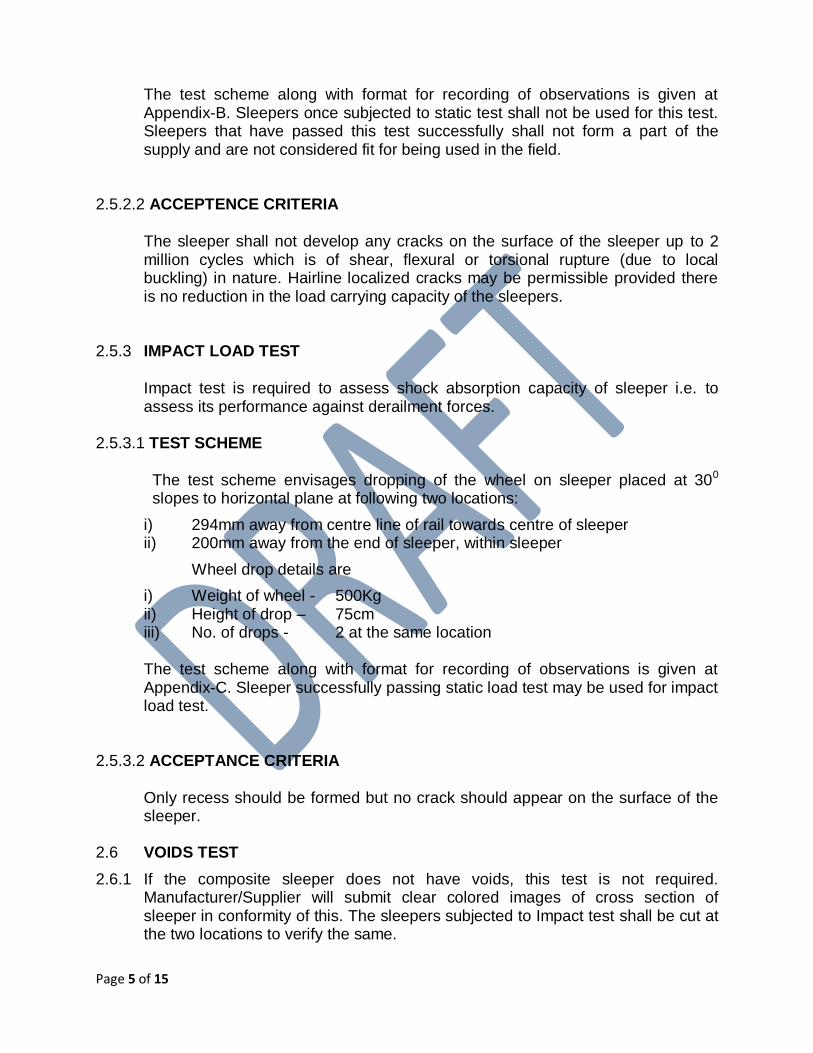
The test scheme along with format for recording of observations is given at Appendix-B. Sleepers once subjected to static test shall not be used for this test. Sleepers that have passed this test successfully shall not form a part of the supply and are not considered fit for being used in the field.
2.5.2.2 ACCEPTENCE CRITERIA
The sleeper shall not develop any cracks on the surface of the sleeper up to 2 million cycles which is of shear, flexural or torsional rupture (due to local buckling) in nature. Hairline localized cracks may be permissible provided there is no reduction in the load carrying capacity of the sleepers.
2.5.3 IMPACT LOAD TEST
Impact test is required to assess shock absorption capacity of sleeper i.e. to assess its performance against derailment forces.
2.5.3.1 TEST SCHEME
The test scheme envisages dropping of the wheel on sleeper placed at 300
slopes to horizontal plane at following two locations:
i) 294mm away from centre line of rail towards centre of sleeper ii) 200mm away from the end of sleeper, within sleeper
Wheel drop details are
i) Weight of wheel - 500Kg ii) Height of drop – 75cm iii) No. of drops - 2 at the same location The test scheme along with format for recording of observations is given at Appendix-C. Sleeper successfully passing static load test may be used for impact load test.
2.5.3.2 ACCEPTANCE CRITERIA Only recess should be formed but no crack should appear on the surface of the
sleeper. 2.6 VOIDS TEST
2.6.1 If the composite sleeper does not have voids, this test is not required. Manufacturer/Supplier will submit clear colored images of cross section of sleeper in conformity of this. The sleepers subjected to Impact test shall be cut at the two locations to verify the same.
Page 6 of 15
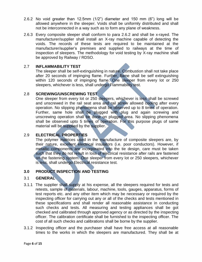
2.6.2 No void greater than 12.5mm (1/2”) diameter and 150 mm (6”) long will be allowed anywhere in the sleeper. Voids shall be uniformly distributed and shall not be interconnected in a way such as to form any plane of weakness.
2.6.3 Every composite sleeper shall conform to para 2.6.2 and shall be x-rayed. The manufacturer/supplier shall install an X-ray machine capable of detecting the voids. The records of these tests are required to be maintained at the manufacturer/supplier’s premises and supplied to railways at the time of inspection of sleepers. The methodology for void testing by X-ray machine shall be approved by Railway / RDSO.
2.7 INFLAMMABILITY TEST
The sleeper shall be self-extinguishing in nature. Combustion shall not take place after 20 seconds of impinging flame. Further, flame shall be self extinguishing within 120 seconds of impinging flame. One sleeper from every lot or 250 sleepers, whichever is less, shall undergo Flammability test.
2.8 SCREWING/UNSCREWING TEST
One sleeper from every lot or 250 sleepers, whichever is less shall be screwed and unscrewed in the rail seat area and rail screw allowed cooling after every operation. No slipping phenomena shall be observed up to 8 times of operation. Further, same hole shall be plugged with plug and again screwing and unscrewing operation shall be done on plugged area. No slipping phenomena shall be observed upto 5 times of operation. For this purpose plugs of same material will be supplied by the supplier.
2.9 ELECTRICAL PROPERTIES
The polymer matrices used in the manufacture of composite sleepers are, by their nature, excellent electrical insulators (i.e. poor conductors). However, if metallic components are incorporated into the tie design, care must be taken such that they do not result in loss of electrical resistance after rails are fastened on the fastening system. One sleeper from every lot or 250 sleepers, whichever is less, shall undergo Electrical resistance test.
3.0 PRODUCT INSPECTION AND TESTING
3.1 GENERAL
3.1.1 The supplier shall supply at his expense, all the sleepers required for tests and retests, sample of materials, labour, machine, tools, gauges, apparatus, forms of test reports etc. and any other item which may be necessary or required by the inspecting officer for carrying out any or all of the checks and tests mentioned in these specifications and shall render all reasonable assistance in conducting such checks and tests. All measuring and testing appliances shall be got checked and calibrated through approved agency or as directed by the inspecting officer. The calibration certificate shall be furnished to the inspecting officer. The cost of all such checks and calibrations shall be borne by the supplier.
3.1.2 Inspecting officer and the purchaser shall have free access at all reasonable times to the works in which the sleepers are manufactured. They shall be at

Page 7 of 15
liberty to inspect the manufacture/testing of sleepers at any stage and to reject sleepers which do not conform to specification.
3.2 TYPE TEST /INITIAL TEST FOR PRODUCT APPROVAL FOR TRIAL
The supplier shall submit 10 nos. prototype sleepers of size 2750 mm x 250 mm x 180 mm at Bridges & Structure Directorate’s laboratory of RDSO.
3.2.1 All (100%) sleepers should fulfill dimensional requirement stipulated in clause 2.3.
3.2.2 The supplier should submit test certificate from NABL approved laboratory (ies) for fulfillment of physical and mechanical performances stipulated in clause 2.4. They shall submit clear colored images of cross-section of sleeper to show whether composite sleepers are having voids. The same shall be verified by cutting the sleepers subjected to Impact test at two locations. They shall submit the methodology for void testing so that stipulation at clause 2.6.2 may be ensured. The supplier shall further submit certificate that sleepers conform to the provisions regarding inflammability and screwing/un-screwing given at clause 2.7 & 2.8.
3.2.3 Regarding fulfillment of structural requirements, the following tests shall be conducted at laboratory at RDSO :
3.2.3.1Static Load Test:
3 nos sleepers shall be subjected to Static Load Test as stipulated in clause 2.5.1. All sleepers should fulfill the acceptance criteria for initial product approval.
3.2.3.2Impact Load Test:
3 nos sleepers shall be subjected to Impact Load Test as stipulated in clause 2.5.3. All sleepers should fulfill the acceptance criteria for initial product approval.
3.2.3.3Dynamic Fatigue Test:
3 nos sleepers shall be subjected to Dynamic Fatigue Test as stipulated in clause 2.5.2 only after sleepers tested for Static Load and Impact Load Tests pass the respective acceptance criteria. All sleepers should fulfill the acceptance criteria.
3.2.4 The above three tests: Static Load Test, Impact Load Test & Dynamic Fatigue Test shall constitute one round of testing. ln case of failure of samples in the first round of test, the firm may be given one more chance, if the firm so desires. For this, the firm shall submit another set of improved samples within three months from the date of advice of failure. The test results of parameters found non-conforming to acceptance criteria would be intimated to the firm. lf the firm desires to offer the improved samples for second round of testing, the firm shall inform in writing, the technical corrective steps taken. Having satisfied with the steps taken by the firm, the sample may be taken for retesting along with testing

Page 8 of 15
charges for retesting. If the samples submitted for retesting fail, the case will be closed.
3.2.5 The prototype sleepers shall be approved by RDSO after technical scrutiny of test certificates and carrying out laboratory tests described in preceding clauses.
3.3 INSPECTION AND TESTS FOR FIELD TRIAL AFTER TYPE TEST/INITIAL APPROVAL
3.3.1 All sleepers shall be dimensionally within tolerance given in clause 2.3. 100% of composite sleeper to be supplied shall be checked visually and dimensionally, and recorded in Appendix-D.
3.3.2 All the parameters given in table-I of clause 2.4 shall be tested by ASTM or any other approved method agreed by RDSO in NABL approved laboratory for every production lot or 250 sleepers, whichever is less and test certificate shall be produced by the supplier at the time of inspection.
3.3.3 STATIC LOAD TEST
Minimum one sleeper for every 250 sleepers supplied or part thereof shall be subjected to Static Load test as per clause 2.5.1. The test sleepers shall be randomly selected from the lot. This test shall be conducted in the supplier’s premises in presence of RDSO/Railway’s representative. In case of failure of any sleeper in this test, the production lot shall be subjected to further test on randomly selected two sleepers from the rest of the sleepers. In case of failure of any of the two randomly selected sleepers, the whole lot will be rejected. Sleeper successfully passing this test may be used for impact test.
3.3.4 IMPACT LOAD TEST
Minimum one sleeper for every 250 sleepers supplied or part thereof shall be tested as per clause 2.5.3. Sleepers successfully passed in the static test, may also be used for impact test. This test shall be conducted in the supplier’s premises in presence of RDSO/Railway’s representative. In case of failure of any sleeper in this test, the production lot shall be further subjected to another test on randomly selected two sleepers from rest of the sleepers. If any one of the two sleepers fails in this test, whole lot will be rejected.
3.3.5 VOIDS TEST
If the composite sleeper does not have voids, this test is not required. In case of composite sleepers having voids, every composite sleeper shall conform to para 2.6.2 and shall be X-rayed. The void testing shall be carried out as per clause 2.6.3.

Page 9 of 15
3.3.6 INFLAMMABILITY TEST
One sleeper from every lot or 250 sleepers, whichever is less, shall undergo inflammability test as per clause 2.7 in the supplier’s premises. In case of failure of any sleeper in this test, the production lot shall be subjected to further test on randomly selected two sleepers from the rest of the sleepers. In case of failure of any of the two randomly selected sleepers, the whole lot will be rejected.
3.3.7 SCREWING/UNSCREWING TEST
One sleeper from every lot or 250 sleepers, whichever is less shall be subjected to this test as per clause 2.8 in the supplier’s premises. In case of failure of any sleeper in this test, the production lot shall be subjected to further test on randomly selected two sleepers from the rest of the sleepers. In case of failure of any of the two randomly selected sleepers, the whole lot will be rejected.
4 MARKING
4.1 Every sleeper shall be permanently marked by way of punching/stenciling with manufacturer’s name, batch no., month and year of manufacturing.
4.2 Any sleeper not meeting the above specifications will be rejected and marked red at the end of the sleeper. Such sleepers shall be cut in at least two parts to avoid intermingling of rejected sleepers with passed ones.
5 LOADING AND DISPATCH
Only those sleepers which have been passed, marked and accepted by the inspecting officer shall be loaded for dispatch.
6 GUARANTEE
The sleepers shall be guaranteed by the supplier for sound manufacture and service for a period of 5 years from the date of its supply duly taking into account the field conditions prevailing on Indian Railways under which the sleeper will be used. If during the guarantee period any sleeper develops defects attributable to bad material, workmanship and/or dimensions requiring withdrawal from service, the cost of sleepers and their replacement shall be borne by the supplier. Any sleeper, required to be removed from track on account of defects of whatever nature would be treated as failed. The defective sleepers withdrawn from service may have to be subjected to further testing so as to establish the cause of failure and to make sure that other sleepers from the lot will not develop similar defects. Cost of such tests will have to be borne by the supplier. Decision of IR/RDSO about reasons of failure shall be treated as final and will be binding on the manufacturer / supplier.
Page 10 of 15
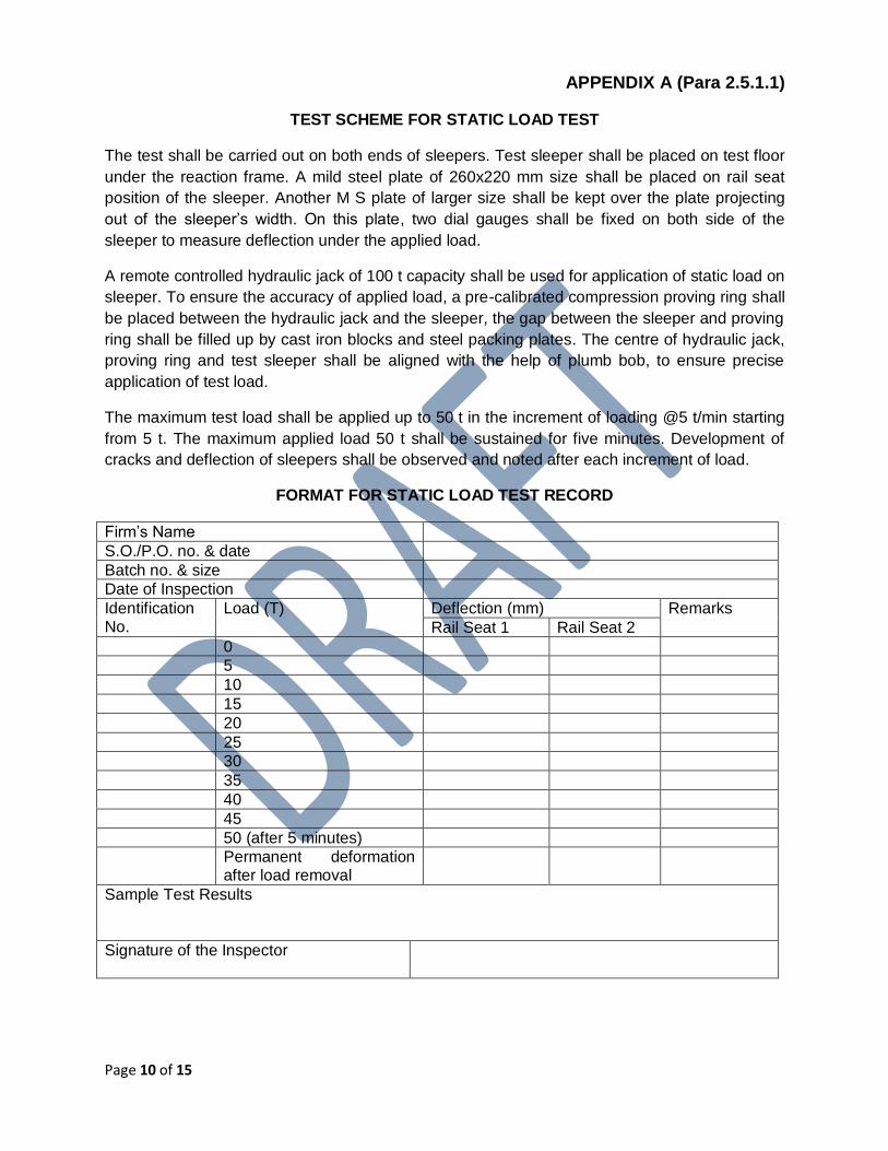
APPENDIX A (Para 2.5.1.1)
TEST SCHEME FOR STATIC LOAD TEST
The test shall be carried out on both ends of sleepers. Test sleeper shall be placed on test floor
under the reaction frame. A mild steel plate of 260x220 mm size shall be placed on rail seat
position of the sleeper. Another M S plate of larger size shall be kept over the plate projecting
out of the sleeper’s width. On this plate, two dial gauges shall be fixed on both side of the
sleeper to measure deflection under the applied load.
A remote controlled hydraulic jack of 100 t capacity shall be used for application of static load on
sleeper. To ensure the accuracy of applied load, a pre-calibrated compression proving ring shall
be placed between the hydraulic jack and the sleeper, the gap between the sleeper and proving
ring shall be filled up by cast iron blocks and steel packing plates. The centre of hydraulic jack,
proving ring and test sleeper shall be aligned with the help of plumb bob, to ensure precise
application of test load.
The maximum test load shall be applied up to 50 t in the increment of loading @5 t/min starting
from 5 t. The maximum applied load 50 t shall be sustained for five minutes. Development of
cracks and deflection of sleepers shall be observed and noted after each increment of load.
FORMAT FOR STATIC LOAD TEST RECORD
Firm’s Name
S.O./P.O. no. & date
Batch no. & size
Date of Inspection
Identification No.
Load (T) Deflection (mm) Remarks
Rail Seat 1 Rail Seat 2
0
5
10
15
20
25
30
35
40
45
50 (after 5 minutes)
Permanent deformation after load removal
Sample Test Results
Signature of the Inspector

Page 11 of 15
APPENDIX B (Para 2.5.2.1)
TEST SCHEME FOR DYNAMIC LOAD TEST
The drawing of dynamic loading arrangement is given below:
The direction of transfer of loading on rail head is arranged in such a way that 40% of
applied vertical load may be converted into horizontal load on the rail. For this purpose,
a loading frame is designed to suit the required loading parameters as per the test
scheme. The applied dynamic vertical load range shall be 4.0 T to 20.0 T (39.2KN to
196.2KN) and frequency of loading shall be 5 Hz. Both rail seats of the sleepers shall be
tested under dynamic conditions for the specified loadings and frequency
simultaneously.
A panel of three sleepers is made for testing of one sleeper. This panel is supported on
a loading stool designed and sleepers are fixed with the help of hook bolts. Canted
bearing plate is fixed on the rail seat surface in between the rail bottom and sleeper top.
Vertical load of specified range (4.0 T to 20.0 T) are applied through actuators at both
rail seats of the central sleeper simultaneously at the frequency of 5 Hz. Average
deflections below both rail seats are recorded under 20.0 T static load with the help of
dial gauge after completion of every 2.5 lakh cycles of loading. Permanent set at both
rail seats are also measured/calculated after completion of 2.0 million cycle of loading
for the central sleeper in each case.
The details of loading parameters and observations made during testing of sleepers
shall be recorded.

Page 12 of 15
Format for Dynamic Load Test Record
Firm’s Name
S.O./P.O. no. & date
Batch no. & size
Date of Inspection
Identification No.
Load (T) Frequency No. of Cycles
Deflection (mm)
Remarks
Max. Min
2,50,000
5,00,000
7,50,000
10,00,000
12,50,000
15,00,000
17,50,000
20,00,000
Sample Test Results
Signature of the Inspector

Page 13 of 15
APPENDIX C (Para 2.5.3.1)
TEST SCHEME FOR IMPACT LOAD TEST
Sleeper shall be placed on two nos. bearing plates at an inclination of 30 degree, under a loco
wheel of approximate weight 500 kg, hanged on the test frame (Pl. refer the sketch). The wheel
shall be tied with one end of a wire rope and the other end of the wire rope is attached with the
lifting and pulling machine. The lifting and pulling machine is used to keep the wheel at desired
height and for sudden drop on the sleeper. The position of the wheel and location of strike on
sleeper shall be aligned before drop. The wheel shall be positioned at the height of 75 cm from
the edge of sleeper and dropped freely releasing the lever of pulling machine on both ends of
the sleeper at two locations i.e. 200 mm away from the sleeper end within sleeper and 294 mm
away from the center line of the rail towards center of sleeper. The wheel shall be dropped twice
at each of four locations on the sleeper.
FORMAT FOR IMPACT LOAD TEST RECORD
Firm’s Name
S.O./P.O. no. & date
Batch no. & size
Date of Inspection
Identification No.
Location of Impact
Size of groove and damaged portion in mm Remarks
After 1st drop of wheel
After 2nd drop of wheel
a b c d a b c d
Sample Test Results
Signature of the Inspector

Page 14 of 15
SKETCH FOR TEST SCHEME FOR IMPACT LOAD TEST

Page 15 of 15
APPENDIX D (Para 3.3.1)
Format for Dimension Record
Firm’s Name
S.O./P.O. no. & date
Batch no. & size
Date of Inspection
Sleeper No.
General Dimensions Rail Seat (Surface Flatness)
Remarks
L W D 1 2 1 2 3 4
Signature of the Inspector