draft conceptual repository design technical memorandum...
TRANSCRIPT

DRAFT CONCEPTUAL REPOSITORY DESIGN
TECHNICAL MEMORANDUM
BLACK PINE MINE
Prepared for Montana Department of Environmental
Quality Federal Superfund Section
Prepared by Herrera Environmental Consultants, Inc.
In association with
Trihydro Corporation


CONCEPTUAL REPOSITORY DESIGN TECHNICAL MEMORANDUM
BLACK PINE MINE
Prepared for
Montana Department of Environmental Quality Federal Superfund Section
Cogswell Building, 1400 Broadway P.O. Box 200901
Helena, Montana 59620-0901
Prepared by Herrera Environmental Consultants, Inc.
101 East Broadway, Suite 610 Missoula, Montana 59802
Telephone: 406/721-4204
In Association With Trihydro Corporation
2707 Broadwater Avenue Helena, Montana 59601
Telephone: 406/588-4180
June 30, 2014 Revised Draft

i
CONTENTS 1. Introduction ............................................................................................. 1
2. Design Criteria .......................................................................................... 1
2.1. Regulatory Requirements ........................................................................ 1 2.2. Design Components ............................................................................... 4
2.2.1. Excavation ............................................................................. 4 2.2.2. Subgrade Preparation ................................................................ 4 2.2.3. Stockpile Areas ........................................................................ 5 2.2.4. General Requirements for USFS Roads ............................................ 5 2.2.5. Waste Placement ..................................................................... 5 2.2.6. Cover System Components .......................................................... 5 2.2.7. Stormwater Conveyance ............................................................. 7 2.2.8. Temporary Erosion and Sedimentation Control (TESC) ......................... 7
3. Excavation and Filling Plan ........................................................................... 8
3.1. Excavation .......................................................................................... 8 3.2. Waste Placement .................................................................................. 8
4. Winter Cover Evaluation............................................................................... 9
5. Material Quantities ................................................................................... 110
6. References ............................................................................................. 132

ii
TABLES Table 1-1. Repository ARARs, Black Pine Mine. ......................................................... 3
Table 4-1. Winter Cover Evaluation, Black Pine Mine. .............................................. 110
Table 5-1. Material Quantities, Black Pine Mine. ..................................................... 110
APPENDICES A Conceptual Repository Plans B Waste Hauling Production Rate Evaluation C Clay Winter Cover Calculations


June 2014
1 Draft Conceptual Repository Design Criteria
1. INTRODUCTION The Montana Department of Environmental Quality, Federal Superfund Section (DEQ) contracted Herrera Environmental Consultants (Herrera), in association with Trihydro Corporation (Trihydro), to prepare a Conceptual Repository Design for the Black Pine Mine (BPM). The onsite repository will serve as a long-term waste storage facility for solid media wastes and materials impacted by historic mining at the BPM.
A Repository Investigation was performed in 2012 to evaluate the preferred repository location and to confirm that the repository would comply with the DEQ’s Applicable or Relevant and Appropriate Requirements (ARARs). A Repository Investigation Report was prepared in 2013 and presented the findings from test pitting, borings, and lab analyses. The Repository Investigation Report concluded that the preferred repository location is suitable for long-term waste storage (Herrera/Trihydro 2013). The results from the Repository Investigation provide the background information to prepare the Conceptual Repository Design. This Technical Memorandum (Tech Memo) outlines the design criteria used to develop the repository, conceptual layout, winter shutdown, and excavation and filling plans.
Additional supporting information is presented in the Reclamation Investigation (RI) Report (Herrera/Trihydro 2012) and the Repository Investigation Report (Herrera/Trihydro 2013).
2. DESIGN CRITERIA 2.1. Regulatory Requirements
DEQ ARARs provide the regulations for the repository design. Table 1-1 presents the repository ARARs. Investigations, material analyses, and geotechnical evaluations were performed during the Repository Investigation (Herrera/Trihydro 2013) to confirm that the siting and development of the repository will comply with the ARARs.

June 2014
Draft Conceptual Repository Design Criteria 2
Table 1-1. Repository ARARs, Black Pine Mine.
Montana Solid Waste Management Act and Regulations
Description Applicable/Relevant and Appropriate
Montana Solid Waste Management Act and
Regulations, Section 75-10-201, et seq., MCA,
ARM 17.50.1001, et seq.
Provides that the management system of any solid waste
facility must protect the public health and safety and
conserve natural resources.
Relevant and Appropriate. These standards
provide sound guidance for any solid waste
facility for the treatment, storage, or disposal
of mine wastes.
Floodplains, ARM 17.50.1004 Provides that a solid waste facility located within the 100-
year floodplain may not restrict the flow of the 100-year flood,
reduce the temporary water storage capacity of the
floodplain, or result in washout of solid waste that poses a
hazard to human health or the environment.
Applicable. If a new solid waste repository is
constructed or existing solid waste facility is
expanded in the 100-year floodplain, it will not
restrict the flow of 100-year flood. In any
event, disposal of mine wastes within a
floodplain is to be avoided per other ARAR
requirements.
Wetlands, ARM 17.50.1005 Prohibits the location of a solid waste facility in a wetland,
unless there is no practicable alternative.
Applicable. New solid waste facilities will not
be located in a wetland.
Fault Areas, ARM 17.50.1006 Prohibits the location of a solid waste facility within 200 feet
(60 meters) of a fault that has had displacement in Holocene
time unless an alternative setback will prevent damage to the
solid waste facility and will protect human health and the
environment.
Applicable. New solid waste facilities will not
be located within 200 feet of a fault that has
had displacement in Holocene time.
Seismic Areas, ARM 17.50.1007 Prohibits the location of a solid waste facility in a seismic
impact zone unless the solid waste structure is designed to
resist the maximum horizontal acceleration in lithified earth
material for the site.
Applicable. New solid waste facility will not be
located in a seismic impact zone.
Unstable Areas, ARM 17.50.1008 Prohibits the location of a solid waste facility in an unstable
area (determined by local soil conditions, local geographic or
geomorphologic features, and local artificial features or
events) unless the solid waste facility is designed to protect
its structural components.
Applicable. New solid waste facilities will not
be located in an unstable geologic area or will
be designed to protect the structural
components of the facility.
Location Restrictions, ARM 17.50.1009 Requires that a solid waste facility must have sufficient Applicable. The listed requirements apply to

June 2014
3 Draft Conceptual Repository Design Criteria
acreage and adequate separation of wastes from underlying
groundwater or adjacent surface water, be located so as to
prevent pollution of water systems, be accessible, and allow
for reclamation of the land.
management and disposal of mine wastes at
the site.
Section 75-10-212, MCA Prohibits dumping or abandoning any debris or refuse upon
or within 200 yards of any State road, other public property,
or private property where hunting, fishing or other recreation
is permitted.
Applicable. The listed requirements apply to
management and disposal of mine wastes at
the site.

June 2014
4 Draft Conceptual Repository Design Criteria
2.2. Design Components 2.2.1. Excavation
The repository will be constructed partially below grade and partially above grade. An initial excavation, approximately 10 feet deep and totaling 159,200 cubic yards (cy), will be completed to provide clean materials for capping the repository and backfilling waste excavation areas (Appendix A, Sheet 5). This excavation will also reduce the height of the repository above the native ground surface, allowing the repository to better blend with the surrounding terrain. Approximately 159,200 cy of waste will be placed below the existing grade, with the remaining 233,000 cy placed above grade.
The excavation side slopes will be no steeper than 2 horizontal (H): 1 vertical (V) and are currently set at 3H:1V, as shown on Sheets 7 and 8 in Appendix A. The excavated bottom slope will mimic (parallel) the original ground slope, and will be designed with a minimum slope of 3 percent (33H:1V) and a maximum slope of not more than 20 percent (5H:1V) (Appendix A, Sheet 5). The bottom will also be developed with a cross-slope to route interim construction surface water to a sump along the northern perimeter of the repository (Appendix A, Sheet 5).
Materials excavated from the repository footprint will be segregated based on their properties and intended use (waste excavation backfill, soil cover, lower permeability clay materials, cover soil/topsoil, rock armor). These materials will be placed in stockpiles downslope of the repository.
2.2.2. Subgrade Preparation Preparation of the subgrade in the bottom of the repository will include compacting and proof rolling the surface. Areas of unsuitable material (e.g., wet, yielding/pumping soils) will be excavated and replaced with compacted, suitable onsite material. The subgrade will be prepared such that it provides a firm base that allows for equipment to operate without rutting the subgrade.
Where competent bedrock is encountered, excavation grades will be adjusted. In areas where weathered bedrock or higher permeability materials (e.g., silty gravel with sand and cobbles) are encountered, the subgrade will be over-excavated 1 foot. Lower permeability material (e.g., clay, silt, and clayey gravel) borrowed during the excavation of the repository will be placed and compacted in these over-excavated areas.
The repository is configured as a closed depression; therefore, a sump will be excavated along the northern perimeter to provide interim water management prior to waste filling (Appendix A, Sheet 5). Saturated or yielding material or accumulated sediments and debris at the sump location will be excavated and replaced with compacted suitable material prior to waste placement.

June 2014
Revised Draft Conceptual Repository Design Criteria 5
2.2.3. Stockpile Areas Material excavated from the repository footprint will be stockpiled for later use as backfill in waste excavation areas (Combination Mill) and as the cover system for the repository. Approximately 159,200 cy of material will be excavated from the repository footprint. Segregating and stockpiling this material will require a large area, measuring at least 200 feet by 400 feet. This stockpile area is planned to be located north of the repository, downslope from the existing power line road (Appendix A, Sheets 4 -6).
Additional stockpile areas may be developed near waste excavation areas. Stockpiles will be contained within designated and controlled areas. Each area will be graded to provide positive drainage away from stockpile material.
2.2.4. General Requirements for USFS Roads Relocation of USFS Road 678 around the repository will be designed to meet USFS road standards for a maintenance level 3 road (USFS 2014) (Appendix A, Sheet10).
2.2.5. Waste Placement The physical (e.g., grain size, natural moisture content, optimal moisture content) and chemical properties of the wastes to be placed in the repository vary depending on location. Wastes will be mixed as they are placed in the repository, or in some cases prior to hauling to the repository, to obtain optimal characteristics for compaction and stability. The mixed waste materials will be moisture conditioned as necessary, placed in 1 foot loose lifts, and compacted to 95% of standard Proctor maximum dry density.
Waste fill slopes in the repository will be limited to 3H:1V; although, temporary steeper slopes may be constructed during waste placement. The conceptual design for the repository calls for the majority of slopes to be flatter than 4H:1V. Slope stability will be verified as part of the final repository design.
The final repository surface will be graded to blend with the surrounding native topography, but will not exceed 3H:1V. The waste will be placed in a manner to provide drainage swales and minor ridges to breakup sheet flow, reduce erosion, and provide positive drainage to the north (Appendix A, Sheet 6).
2.2.6. Cover System Components The repository cover system must provide adequate separation, protection, and barrier of waste from native materials. The cover system (Appendix A, Sheet 11) will be designed to reduce permeability to less than 1x10⁻⁵ centimeters per second (cm/sec), and will consist of the following components from top to bottom:

June 2014
6 Draft Conceptual Repository Design Criteria
An erosion protection layer consisting of a 0.5-foot layer of cover soil/topsoil with vegetation, or a 0.5-foot layer of native rock;
A soil cover consisting of a 2.5-foot layer of native soil;
A Composite Drainage Net (CDN) to collect and convey infiltrating water;
A 60-mil thick, textured High Density Polyethylene (HDPE) geomembrane; and
A protection layer comprised of compacted waste that is smooth and free of projections that can damage the overlying geomembrane.
Geomembrane and CDN will terminate in anchor trenches along the perimeter of the repository. The anchor trenches will be a minimum of 2 feet deep (Appendix A, Sheet 11). Along the northern perimeter/toe of the repository, the CDN will terminate in a gravel-filled collection trench or the bottom of a surface water collection ditch (Appendix A, Sheets 6 and 11). This trench or ditch will convey flow that infiltrates through the soil cover and is collected by the CDN away from the repository toward the culvert under the re-aligned USFS road.
With the exception of the CDN and HDPE geomembrane, cover system materials will be obtained from materials excavated from the repository footprint. The onsite soils will segregated during the repository excavation and screened as necessary based on the soil properties and intended use.
As noted in the Repository Investigation Report, there is limited cover soil/topsoil available at the BPM. In an effort to limit new disturbance, the erosion layer will be a combination of vegetative cover and native rock armor. Based on investigations completed, sufficient cover soil exists within the footprint of the repository to cover approximately 6.4 acres of the repository. Areas covered with cover soil/topsoil will be hydroseeded. The remaining area (approximately 10.1 acres) will be protected with native rock, which will appear similar to existing rock-covered slopes in the area. The rock will be obtained by screening native material excavated from the repository subgrade.
The protection layer, which underlies the 60-mil HDPE geomembrane will be constructed of waste. Depending on the construction sequencing and timing, this layer may be covered with a temporary winter cover (Section 4). This winter cover will provide adequate protection, when combined with appropriate waste placement and compaction, to protect the overlying geomembrane. If construction timing is such that the last lift of waste material is not covered by a winter cover, and depending on the physical characteristics of the waste material, a non-woven geotextile will be considered for placement between the waste and the overlying geomembrane as a protection layer.

June 2014
Revised Draft Conceptual Repository Design Criteria 7
2.2.7. Stormwater Conveyance Stormwater diversion (run-on) ditches will be constructed upslope of the repository to collect surface water runoff from upslope watersheds and convey the runoff away from the repository. Stormwater collection ditches will be constructed downslope of the repository to collect surface water runoff generated by precipitation falling directly on the repository and convey this runoff away from the repository. These ditches will be excavated into and constructed from native materials. Stormwater collection or diversion ditches will meet the following design criteria:
Maximum drainage grades will be such that the need for rock armor or other energy dissipaters is minimized.
Design velocity will be determined using a Manning’s coefficient (n) equal to 0.035 for rock –lined ditches and 0.030 for vegetated ditches.
The maximum allowable design velocity will be 5.0 feet per second (fps) for vegetated ditches (n = 0.030), unless also lined with turf reinforcement matting
Ditches will be triangular in cross-section.
Side slopes will be no steeper than 1H:1V. Side slopes will be flatter where allowed by the surrounding terrain, with 3H:1V side slopes preferred. However, localized 1H:1V side slopes will be allowed in areas to minimize excavation/disturbance.
Ditches will be designed to convey the peak 25-year, 24-hour flow.
Run-on control berms may also be used to divert stormwater away from the repository. Run-on control berms will meet the following design criteria:
Sizing and geometry criteria will be the same as identified for ditch design.
Minimum berm top width shall be 3 feet.
Berms shall be designed to convey the peak 25-year, 24-hour flow.
2.2.8. Temporary Erosion and Sedimentation Control (TESC) Best Management Practices (BMPs) will be applied during construction to reduce the opportunity for sediments or waste to be transported offsite. BMPs will include straw wattles, berms, and silt fence for sedimentation control and stabilized construction entrances for truck traffic. A temporary sediment basin will also be constructed downslope from the repository. This sediment basin will be maintained for the duration of the repository construction (Appendix A, Sheets 4-6).

June 2014
8 Draft Conceptual Repository Design Criteria
3. EXCAVATION AND FILLING PLAN The repository subgrade is planned to be excavated during one construction season, with waste placement and construction of the repository cover in subsequent construction seasons. Production rates for a variety of haul trucks, ranging from side dumps to 40-ton articulated trucks, were evaluated to estimate the required waste hauling time. A table summarizing this evaluation is provided as Appendix B. Based on this evaluation, placing waste in the repository could reasonably be completed over two, 4-month long construction seasons. This would require that approximately 200,000 cy of waste be excavated, hauled, and placed each field season. Completing the repository cover and project cleanup would require a fourth construction season.
3.1. Excavation A run-on ditch will be cut along the up gradient extents (southern perimeter) of the repository to collect and divert surface water from entering the excavation. The repository will be excavated to the grades and slopes shown on the conceptual plans (Appendix A, Figure 5). A sump will be excavated in the northern center portion of the repository to collect water during the first winter season. A culvert will be installed across the existing power line road on the northern boundary of the repository to convey water from the excavation to a sediment basin down gradient of the repository (Appendix A, Figure 5). Prior to waste placement, the excavation bottom grades will be finish graded and saturated or yielding soils, or accumulated sediment and debris, associated with the sump will be removed.
3.2. Waste Placement Waste will be hauled from both the Smart Creek drainage (Combination Mine) and the South Fork Lower Willow Creek drainage (Tim Smith waste rock dumps, Combination Mill, and South Fork Lower Willow Creek stream sediments) using existing USFS roads. Access into the repository will be from the north and the south to allow for haul trucks to access from two locations. Hauling from both areas simultaneously will reduce truck congestion. The existing USFS roads will not be widened to allow for two-way traffic; however, temporary turn-outs will be constructed and used to allow haul trucks to pass each other. Segments of the existing USFS roads, such as tight turns or corners, may also be upgraded/widened to allow for haul trucks.
Waste will be moisture conditioned and/or mixed, and placed in the repository in compacted 1 foot lifts. Waste will be placed in the repository such that a slope is maintained toward drainage points along the northern repository perimeter. Waste placement will begin along the northern edge of the repository and fill from north to south to allow for positive drainage and to reduce ponding. Placement will proceed up gradient to the south. Drainage will be directed from the repository into the drainage ditch running along the northern edge of the repository and then to the sediment basin.
June 2014
Revised Draft Conceptual Repository Design Criteria 9
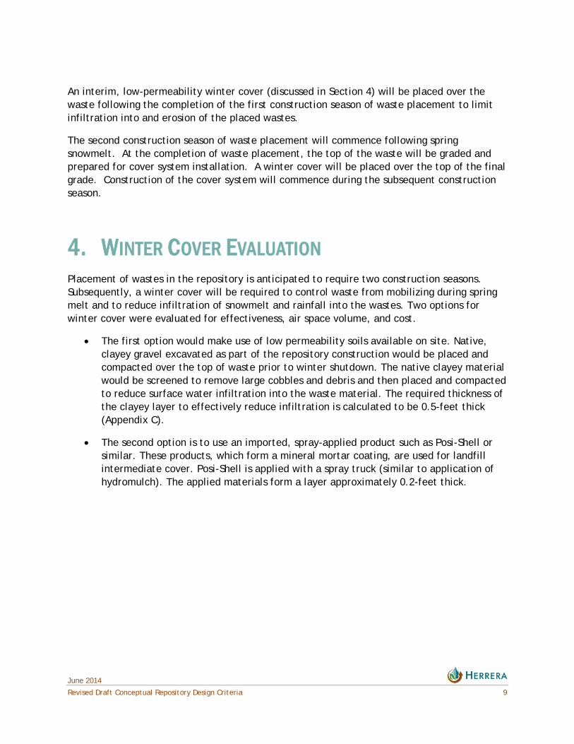
An interim, low-permeability winter cover (discussed in Section 4) will be placed over the waste following the completion of the first construction season of waste placement to limit infiltration into and erosion of the placed wastes.
The second construction season of waste placement will commence following spring snowmelt. At the completion of waste placement, the top of the waste will be graded and prepared for cover system installation. A winter cover will be placed over the top of the final grade. Construction of the cover system will commence during the subsequent construction season.
4. WINTER COVER EVALUATION Placement of wastes in the repository is anticipated to require two construction seasons. Subsequently, a winter cover will be required to control waste from mobilizing during spring melt and to reduce infiltration of snowmelt and rainfall into the wastes. Two options for winter cover were evaluated for effectiveness, air space volume, and cost.
The first option would make use of low permeability soils available on site. Native, clayey gravel excavated as part of the repository construction would be placed and compacted over the top of waste prior to winter shutdown. The native clayey material would be screened to remove large cobbles and debris and then placed and compacted to reduce surface water infiltration into the waste material. The required thickness of the clayey layer to effectively reduce infiltration is calculated to be 0.5-feet thick (Appendix C).
The second option is to use an imported, spray-applied product such as Posi-Shell or similar. These products, which form a mineral mortar coating, are used for landfill intermediate cover. Posi-Shell is applied with a spray truck (similar to application of hydromulch). The applied materials form a layer approximately 0.2-feet thick.

June 2014
10 Draft Conceptual Repository Design Criteria
A comparison of the two cover options is presented in Table 4-1.
Table 4-1. Winter Cover Evaluation, Black Pine Mine.
Native Clayey Gravel
Posi-Shell (or similar
product)
Winter Shutdown Cover Volume by Year (cy) 13,300 5,300
Total Winter Shutdown Cover Volume (cy)1 26,600 10,600
Cost per Winter Cover Lift $66,5502 $35,9433
Total Cost $133,100 $71,886 1 Total volume based on two winter shutdowns. 2 Cost for native clayey gravel material includes excavation, selective processing, placement, and compaction. Unit cost is $5.00/cy. 3 Costs for Posi-Shell include application through a sprayer. Unit cost is $0.05/square foot (sf).
Posi-shell and the native clayey gravel material have similar permeability characteristics, but the Posi-Shell takes up less than half of the airspace that the native clayey gravel would require. Posi-Shell will also cost nearly half the estimated cost to process, place, and compact the native clayey gravel material. Posi-shell, or similar products, offer the additional benefit of shorter application timeframes, which will allow the contractor to extend waste excavation and hauling activities.
Based on the evaluation of the winter cover options, the preferred winter cover would be application of Posi-Shell, or similar product. The benefits or limitations of these types of products will be further evaluated with suppliers during development of the repository design. Final selection of a winter cover alternative will be made at that time.
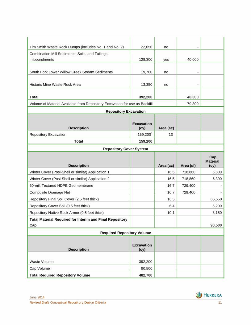
5. MATERIAL QUANTITIES Material quantities for the repository include waste material, winter cover, geomembrane, CDN, soil cover, cover soil, and native rock armor. Borrow material from the repository excavation is also required for backfill in the Combination Mill waste excavation areas. The material quantities are presented in Table 5-1.
Table 5-1. Material Quantities, Black Pine Mine.
Waste Volumes
Area Excavation
(cy) Backfill2 (yes / no)
Backfill
(cy)
Combination Mine Waste Rock
203,2001 no -
Combination Mine Soils Removal Area
5,000 no
-
June 2014
Revised Draft Conceptual Repository Design Criteria 11
Tim Smith Waste Rock Dumps (includes No. 1 and No. 2)
22,650 no -
Combination Mill Sediments, Soils, and Tailings
Impoundments
128,300 yes 40,000
South Fork Lower Willow Creek Stream Sediments
19,700 no -
Historic Mine Waste Rock Area
13,350 no -
Total
392,200 40,000
Volume of Material Available from Repository Excavation for use as Backfill 79,300
Repository Excavation
Description
Excavation
(cy) Area (ac)
Repository Excavation 159,2003 13
Total 159,200
Repository Cover System
Description Area (ac) Area (sf)
Cap Material
(cy)
Winter Cover (Posi-Shell or similar) Application 1 16.5 718,860 5,300
Winter Cover (Posi-Shell or similar) Application 2 16.5 718,860 5,300
60-mil, Textured HDPE Geomembrane 16.7 729,400 -
Composite Drainage Net 16.7 729,400 -
Repository Final Soil Cover (2.5 feet thick) 16.5 66,550
Repository Cover Soil (0.5 feet thick) 6.4 5,200
Repository Native Rock Armor (0.5 feet thick) 10.1 8,150
Total Material Required for Interim and Final Repository
Cap 90,500
Required Repository Volume
Description
Excavation
(cy)
Waste Volume
392,200
Cap Volume 90,500
Total Required Repository Volume 482,700

June 2014
12 Draft Conceptual Repository Design Criteria
Available Repository Volume
Description
Available Volume
(cy) Difference
(cy)
Difference
(%)
Excavation Area Volume below Existing Grade
159,200
Proposed Repository Final Grading Volume above Existing
Grade
308,000
Total 467,200 15,500 3.2
USFS Road Re-alignment Volume Quantities
Description
Total Excavation
(cy) Area (ac) Length (ft)
Cut
2,411
Fill
2,275
Disturbance 1.29
Length 2,076 1The Combination Mine waste rock pile contains approximately 232,000 cy of material, including 29,000 cy of cover material. The clean cover material will be salvaged and replaced following removal of contaminated materials. The volume of contaminated materials to be removed is 203,200 cy. 2 Backfill is not assumed to be required for the Combination Mine waste rock pile or Tim Smith waste rock dumps. These excavation areas will be excavated back to native material and the approximate pre-mining surface. Backfill is not assumed to be required for the Combination Mine soils removal areas or the South Fork Lower Willow Creek stream sediments excavation areas. These excavation areas will be backfilled and blended with the surrounding topography through local grading. 3 Initial repository excavation volume includes approximately 45,000 cy of clayey gravel based on interpolation of test pit and borehole logs from the RI and Repository Investigation (Herrera/Trihydro 2012, Herrera/Trihydro 2013).
6. REFERENCES Herrera/Trihydro. 2012. Reclamation Investigation Report for the Black Pine Mine, Granite County, Montana. Prepared for Montana Department of Environmental Quality, Helena, Montana, by Herrera Environmental Consultants, Inc., Missoula, Montana, and Trihydro Corporation, Helena, Montana. May 2012.
Herrera/Trihydro. 2013. Repository Investigation Report for the Black Pine Mine, Granite County, Montana. Prepared for Montana Department of Environmental Quality, Helena, Montana, by Herrera Environmental Consultants, Inc., Missoula, Montana, and Trihydro Corporation, Helena, Montana. December 2013.

June 2014
Revised Draft Conceptual Repository Design Criteria 13
United States Forest Service. 2014. Email communication from Sonny Thornborrow to Devin Clary regarding FSR #678 Maintenance Level. April 24, 2014.

June 2014
Draft Conceptual Repository Design Criteria
APPENDIX A
Conceptual Repository Plans

June 2014
Revised Draft Conceptual Repository Design Criteria
APPENDIX B
Waste Hauling Production Rate Evaluation

June 2014
Draft Conceptual Repository Design Criteria
APPENDIX C
Clay Winter Cover Calculations