downloading software for the trilogy line of standalone ... version 5 user's guide 1 dl-windows...
TRANSCRIPT

DL-WINDOWS Vers ion 5 User 's Guide 1
DL-WINDOWS™
VERSION 5 USER'S GUIDE
Downloading Software for the Trilogy® Line of Standalone
Access Control Systems
OI382 01/14 (replaces OI237K)
345 Bayview Avenue Amityville, New York 11701
For Sales and Repairs 1-800-ALA-LOCK For Technical Service 1-800-645-9440
or visit us at http://tech.napcosecurity.com/ (Note: Technical Service is for security professionals only)
Publicly traded on NASDAQ Symbol: NSSC
© ALARM LOCK 2014
PDL3500 PDL4500 - "RESIDENCY" LOCK
PDK3000
DK3000
DL3000 DL4100 - "PRIVACY LOCK"
ETDL
DL3500 DL4500 - "RESIDENCY LOCK"
AL-DTM DATA TRANSFER
MODULE
AL-IR1 INFRARED PRINTER
AL-PRE PROX CARD READER/
ENROLLER
PDL3000 PDL4100 - "PRIVACY" LOCK
PL3000

2 DL-WINDOWS Vers ion 5 User 's Guide
The following changes have been made to this manual OI382 (identical to OI237K) since the previous edition (OI237J):
• Updated to reflect DL-Windows version 5 which includes a new look, improved performance and simplified screens. • Page 4, "Supported Products" expanded to include additional lock models.
C H A N G E S F R O M T H E P R E V I O U S E D I T I O N
About this Manual This manual is intended to document the DL-Windows computer screens and features used to program non-wireless door locks and devices. The word "lock" is a generic word used to indicate one of the many Alarm Lock locking devices avail-able, including devices such as the DK series keypads that trigger other locking devices. The word "credential" is also a generic word used to indicate a PIN number pressed into a lock keypad, or a proximity card or proximity keyfob. For infor-mation regarding the programming of the wireless Trilogy Networx™ system, where programming features can be sent wirelessly using a computer network, see OI383.
Important: Trilogy® is a registered trademark of Alarm Lock. ProxCard® and ProxKey® are trademarks of the HID© Corporation.. Microsoft® and Windows® are trademarks of their the Microsoft Corporation. All other trademarks, service marks, and product or service names described in this manual are for identification purposes only and may be trademarks or registered trademarks of their respective owners. The absence of a name or logo in this document does not constitute a waiver of any and all intellectual property rights that NAPCO Security Technologies, Inc. has established in any of its product, feature, or service names or logos. Screen images, icons and instructions in this guide may vary depending on the software version installed. The information in this manual is for informational purposes only and is subject to change without notice. Companies, names and data used in examples herein are fictitious unless otherwise noted. Alarm Lock assumes no responsibility for incorrect information this manual may contain.

DL-WINDOWS Vers ion 5 User 's Guide 3
Table of Contents
Changes from the Previous Edition .................................. 2
About this Manual ............................................................... 2
Supported Products............................................................ 4
Product Communication Examples................................... 5
Terminology ........................................................................ 6
DL-Windows Toolbar .......................................................... 8
DL-Windows Icons and Symbols....................................... 8
DL-Windows Main Menu..................................................... 9
Quick Start Checklist ........................................................ 10
DL-Windows Software Installation Flowchart................. 10
DL-Windows Software Installation .................................. 11
System Requirements ................................................. 11
Before you begin.......................................................... 11
Installing DL-Windows................................................. 11
Starting DL-Windows................................................... 12
DATABASE CONFIGURATION.................................... 12
Configuring as a Server ........................................... 12
Configuring as a Workstation.................................. 13
Database Configuration Options ................................ 13
UPGRADE / IMPORT UTILITY...................................... 13
DL-Windows Administrators and Operators .................. 14
Create New Account and Add Locks............................... 16
"Global Users Screen" Field and Button Definitions..... 18
Add Users with the Global Users Screen........................ 19
Removing / Deleting / Disabling Users (Global Users Screen)............................................................................... 24
Assign Users: Groups/Levels/Double Sided Access..... 25
"Global Users" Screen - Right-Click Menu......................27
Adding Users to the Administrative Users screen .........29
"Lock Data" Screen - Field and Button Definitions ........30
"Schedules" Screen - Field and Button Definitions .......31
"Schedules" Screen - Right-Click Menu..........................32
Creating Time Zones and Events in the Schedule Screen............................................................................................33
Schedules...In More Detail ................................................35
"Schedule View" Screen - Field and Button Definitions ............................................................................................37
"Features" Screen - Options tab ......................................38
"Features" Screen - Relay tab ..........................................40
"Features" Screen - Remote tab.......................................41
"Features" Screen - 4000 Series tab ................................42
Communicating with Locks ..............................................43
"DTM3 Support" Screen - Field and Button Definitions ............................................................................................47
Communicating with the AL-DTM3 ..................................48
"Event Log" Screen - Field and Button Definitions ........52
"Options" Screen - Field and Button Definitions............53
Tools Menu (Expanded) ....................................................54
AL-DTM3 Specifications and Configuration....................56
Glossary .............................................................................57
ALARM LOCK LIMITED WARRANTY ...............................60

4 DL-WINDOWS Vers ion 5 User 's Guide
Infrared Printer (AL-IR1) An AL-IR1 printer is used to print Audit Trails and User Code (PIN) lists (where used) without the need for a PC. Its infrared reader means no cable connection is needed (not for use with Networx™ series locks or devices).
Prox Card Reader/Enroller (AL-PRE) Quickly enroll multiple proximity credentials (cards and keyfobs) into DL-Windows. Use the supplied 9-pin DB9 to DB9 serial cable to connect the AL-PRE to your computer’s serial COM port. Compatible with most HID ProxCards® and ProxKey® keyfobs (37 bits or less). For PDL series proximity locks only.
ProxCard® / ProxKey® Keyfob Compatible with most HID ProxCards® and ProxKey® keyfobs (26-37 bits).
Note: ProxCard® and ProxKey® are trademarks of the HID© Corporation.
Double-ended Mini Banana Plug Connector After you create your lock programming in DL-Windows and transfer the DL-Windows programming to an AL-DTM3, trans-fer the programming from the AL-DTM3 to your lock via a double-ended mini banana plug. You can also use this cable to transfer the lock programming from your lock to an AL-PRE.
DB9 to DB9 Serial Cable Enroll proximity credentials quickly into DL-Windows, then transfer this new proximity data from DL-Windows to the AL-PRE via this 9-pin DB9 to DB9 serial cable. Once the data is in the AL-PRE, you can transfer the data to the lock via the Dou-ble-ended Mini Banana Plug Connector (see above), thus avoiding the need to use an AL-PCI2 cable for this process.
AL-PCI2 Cable The AL-PCI2 cable is required to communicate between your computer’s RS-232 serial communications port and the AL-DTM3 or lock. One end of the AL-PCI2 cable is designed to be plugged into a DB-9 male 9-pin serial COM port. If your computer has a 25-pin COM port only, a 25-pin to 9-pin adapter must be used. The other end of the AL-PCI2 cable features a 2-pin banana plug connector which is polarity sensitive (the TAB marked "GND" must be plugged into the lock’s black left ter-minal). Note: The AL-PCI2 can be used with an MX1130 adapter (see next page). See "AL-PCI2 (USB)" below.
Data Transfer Module (AL-DTM3) The AL-DTM3 allows the transfer of Lock Programs and other data between DL-Windows and locks. See page 56 for detailed AL-DTM3 specifications and feature descriptions.
Supported Products
AL-PCI2 Cable (USB) The AL-PCI2 (USB) cable is required to communicate between your computer’s USB communications port and the AL-DTM3 or lock. One end of the AL-PCI2 (USB) cable is plugged into a computer USB port, and the other end features a 2-pin banana plug connector which is polarity sensitive (the TAB marked "GND" must be plugged into the lock’s black left terminal). Note: All references to communications in this manual will refer to the AL-PCI2 (USB) cable, but if you do not have an AL-PCI2 (USB) cable, you can still use the older AL-PCI2 cable described above. Note: The AL-PCI2 (USB) will eventually replace the older AL-PCI2 (see above), therefore the MX1130 adapter (see next page) will no longer be needed.
LA3125 ALARM LOCK
AL-PCI-USB
H I D
HID CORPORATION
DK3000 / PDK3000 Relay-only locking device, 2000 User Codes (PINs), 500 Schedules, 40,000 Audit Trail events. PDK3000 adds proximity capability. DL3000 / DL2800 300 User Codes (PINs), 150 Schedules, 1600 Audit Trail Events. DL-Windows also supports the similar DL2800, which supports 200 Users. DL3500 / ETDL / ETPDL DL3500: 300 User Codes (PINs), 500 Schedules, 40,000 Audit Trail events. ETDL: 2000 User Codes (PINs), 500 Schedules, 40,000 Audit Trail Events. ETPDL adds proximity credential capability. PDL3000 / PDL3500 / DL3200 2000 User Codes (PINs) / proximity cards or keyfobs, 500 Schedules, 40,000 Audit Trail Events. DL-Windows also supports the similar PDL3500 mortise lock. The cylindrical DL3200 is designed for non-proximity applications.
DL / PDL4100 ("Privacy") DL / PDL4500 ("Residency") The "Residency" feature is specially designed to prevent unintentional lock-out, and the "Privacy" feature is designed to deny access to other users after an individual enters. DL2700 10 Manager Codes, 90 User Codes ("Entry Only"), three "one-time entry" Service Codes, keypad Anti-Tamper Lockout and programmable relay functions. DL5200 / DL5300 / PDL5300 DL5200: Double-sided for controlled entry and exit, includes 10 Manager Codes, 90 User Codes ("Entry Only"), three "one-time entry" Service Codes, 30-second keypad Anti-Tamper Lockout feature. DL5300 adds a real-time clock/calendar and 500 Schedules, and the PDL5300 adds proximity credential capability.
DL/PDL1200 / 1200ET DL/PDL1300 / 1300ET Narrow-stile lock bodies for narrow stile aluminum doors. The "ET" series utilize existing panic exit device mounting holes. 1200 series supports 100 User Codes, 1300 series supports 2000 User Codes with 40,000 Audit Trail events and 500 Schedules. See www.alarmlock.com for complete list of features. PL3000 / PL3500 / ETPL Prox-only for increased security, 1700 Users (1999 with DL-Windows), 40,000 Audit Trail events and 500 Schedules. DL-Windows also supports the similar PL3500 mortise lock; ETPL for use with push bar applications. For a complete list of all supported locking devices, including the wireless Networx system, visit us at www.alarmlock.com.

DL-WINDOWS Vers ion 5 User 's Guide 5
Ethernet Network PC Running
DL-Windows Software
Wired (RJ-45)
or Wireless
GATEWAY #1
Radio ) ) ) ) )
Radio ) ) ) ) )
Wired (RJ-45)
or Wireless
NOTE:
The older AL-PCI2 cable is designed to be used on a 9 pin serial COM port. If your computer has a 25 pin COM port, a 25 pin to 9 pin adapter must be used. Warning: Polarity MUST be observed when connecting cables to the lock. The tab marked with a "–" must plug into the negative (black) hole.
Scenario 4 Use the AL-IR1 Infrared printer to print your lock’s audit trail (Event Log), User Code (PIN) list, clock settings and software version. No cable re-quired.
Scenario 1 Create the program in DL-Windows on your computer, then transfer the program from the computer directly to the lock via an AL-PCI2 cable. Enter the User 298 User Code to send or receive data to of from DL-Windows. When no COM port exists, use a USB to RS-232 cable. Alternatively, you can use an AL-PCI2 (USB) cable in place of the older AL-PCI2 cable.
PDL3000 LOCK
Scenario 2 Create the program in DL-Windows and transfer the program from DL-Windows to an AL-DTM3 (via an AL-PCI2 or AL-PCI2 (USB) cable), then transfer the program from the AL-DTM3 to the lock via a Double-ended Mini Banana Plug Connector). The hand-held AL-DTM3 is useful because you do not have to transport (or find electricity for) your computer. Data can also flow in reverse, from the lock, through the AL-DTM3, back to the computer for examination.
AL-DTM3 DATA TRANSFER MODULE NOTE: OBSERVE TAB DIRECTION WHEN
INSERTING CABLE INTO AL-DTM3 AND LOCK
DOUBLE-ENDED MINI BANANA PLUG CONNECTOR
PDL3000 LOCK
DB9 to DB9 Serial Cable (supplied)
Scenario 3 Enroll proximity credentials quickly into DL-Windows, then transfer this new proximity data from the computer through the AL-PRE to the lock (thus avoiding the need to use an AL-PCI2 or AL-PCI2 (USB) cable). For proximity PDL series locking devices only.
CONNECT DB9 CABLE TO COMPUTER SERIAL
PORT (COM 1-4)
AL-PRE PROXCARD READER/ENROLLER
NOTE: OBSERVE TAB DIRECTION WHEN INSERTING CABLE INTO AL-PRE AND LOCK
DOUBLE-ENDED MINI BANANA PLUG CONNECTOR
PDL3000 LOCK
WINDOWS COMPATIBLE LAPTOP OR DESKTOP PC
AL-IR1 INFRARED PRINTER PDL3000 LOCK
If your computer does not have a serial COM port (DB-9 male) available, you can plug your AL-PCI2 cable into a special USB to RS-232 cable. Order part MX1130 for the USB to RS-232 cable only, or ALPCI2-U for both the USB to RS-232 cable and an AL-PCI2 cable.
Product Communication Examples
Scenario 5 With the Trilogy Networx™ series door locks and keypads, DL-Windows software allows you to upload and download programming features wirelessly using a computer network. See OI383 for more information.
NOTE: OBSERVE TAB DIRECTION
WHEN INSERTING CABLES INTO LOCK
AL-PCI2 (USB) LA3125
ALARM LOCK AL-PCI-USB
(+)
(–)
To USB
AL-PCI2 CABLE CONNECT TO SERIAL PORT (COM 1-4)
WINDOWS COMPATIBLE LAPTOP OR DESKTOP PC
WINDOWS COMPATIBLE LAPTOP OR DESKTOP PC
AL-PCI2 (USB) LA3125
ALARM LOCK AL-PCI-USB
(+)
(–)
To USB
AL-PCI2 CABLE CONNECT TO SERIAL PORT (COM 1-4)

6 DL-WINDOWS Vers ion 5 User 's Guide
DL-Windows DL-Windows is a computer program that allows you to program your Alarm Lock security locking device. You do not need DL-Windows to program your lock, but it makes programming much faster and easier. With DL-Windows, you can quickly create Accounts and Lock Profiles (software that makes the lock perform its many functions) add multiple Users (who have access), add ProxCard® and ProxKey® keyfob proximity credentials, retrieve Event Logs, and create Schedules. DL-Windows allows you to easily set up all lock programming in advance (on your computer), and then send the programming information to the locks at your convenience. This manual will guide you through all aspects of DL-Windows, from the initial software installation procedure through the creation of a Lock Profile, from the transfer of lock programming to the viewing of lock Event Logs. Alarm Lock makes a variety of computer interfaced microprocessor-based programmable keypad-entry and proximity card security locks: DL, PL and PDL Series Access Control Locks. DL Windows works with them all. See OI383 for more information regarding the wireless Networx™ system, its supported locks and features. DL-Windows Administrators and Operators There are two types of people who can control DL-Windows: "Administrators" and "Operators". Upon initial installation, DL-Windows is controlled by a "default" Administrator. The Administrator has full access and complete control over every feature within DL-Windows and possesses the ability to add Operators as necessary. Operators are Users who have limited access and limited "Privileges" (abilities) within DL-Windows. Administrators select those Privileges for each Operator as necessary (e.g. the ability to add Lock Profiles to an Account). See DL-Windows Administrators & Operators, "Setting Operator Privileges". Accounts
An Account is an individual DL-Windows database file that allows you to organize and maintain multiple lock installations. In practical terms, an Account is often named after the building
or company location where a lock or multiple locks have been physically installed. For example, the Account Name might be "Hunterdon Hospital" and within that Account are the four door locks you just installed on the 7th floor. In DL-Windows, Accounts can be created, edited, cloned, protected and deleted. The benefit of an Account is that it allows you to add the name of a User ONCE (in the Global Users screen) and then assign that User to multiple locks within the Account ("building"), rather than having to enter and re-enter the same User information again and again for each lock. Enter the User information once in the Global Users screen, then enable that User in any "Lock Profile" within the Account, as needed. Database All of the Accounts in DL-Windows reside in what is called the "database". DL-Windows controls the security, integrity and organization of Account data in its database, ensuring the data is retrieved reliably and accurately. The database can be created either in a single local installation ("Workstation" installation) or through a network ("Server" installation) where multiple installations of DL-Windows can share one database. See page 11 for information about which type of installation will suit your requirements. Lock Profile
Located within an Account, a Lock Profile contains the instructions that a physical lock uses to perform its various
functions. Use DL-Windows to create the Lock Profile on your computer, and then send the Lock Profile to the physical lock. A Lock Profile is created for each individual physical lock, and maintains the feature settings, User Codes (PINs), Schedules, logs (Audit Trails), etc. As with Accounts, Lock Profiles can be created, edited, cloned, "Linked" and deleted. See OI383 for "Linking" Lock Profiles to wireless Networx locks. PIN / User Code PINs / User Codes, used interchangeably in this manual, are numbers that are 3 to 6 digits in length, and are generally given to each person who you wish to allow access through a door protected by a physical Alarm Lock security locking device. It is the responsibility of the Administrator or Operator (if privileged) to generate User Codes within DL-Windows, and to distribute these User Codes accordingly. Users Not to be confused with "DL-Windows Administrators and Operators" (see above), Users are people that have their personal information and a User Code (PIN) typed into the Global Users screen. As required by the Administrator or Operator (if privileged), these Users are then added (enabled within) desired Lock Profiles, as necessary. For example, 348 people are employed within Hunterdon Hospital, but only User Joe Smith (assigned a PIN number 373823) is allowed access through the Pharmacy Department door lock. Features Your locking device is designed to support several options and functions. Using the Features screen, you can select the features you wish to activate, such as if the lock will automatically adjust for Daylight Saving Time in the spring and autumn, or if the lock sounder should be disabled or enabled. Schedules Your Alarm Lock locking device can be programmed to maintain a "Schedule" in which certain "Events" (recorded lock activities) can occur automatically on specified days and times. For example, you can program a door lock to UNLOCK at 9 AM, LOCK at noon, UNLOCK at 1 PM, and LOCK again at 5 PM, every weekday. As you can see, many different combinations of Schedules can be created to suit the needs of the Users. Using the Schedules screen, create Time Zones (defining the days and times) and link them to Events (lock actions such as "Unlock"). When finished, you can view your Schedule in the Schedule View screen. Note: Full Schedules (Time Zones and Events) may be shared between Lock Profiles and even other Accounts by using the Save / Import feature. See Time Zones, below. Time Zones Events (recorded lock activities) can be programmed to occur at certain times. These times (for example, "every Tuesday at 5 PM") are called "Time Zones". Use the Schedules screen to create these Time Zones, then link Events to these Time Zones. Note: Time Zones are Global to your Account, and are shared between all of the Lock Profiles in the Account; Events are NOT shared between Lock Profiles. Programming Levels The Programming Level defines the range of keypad programming tasks a User (a person listed in the Global Users screen) is allowed to perform. For most locks, the higher the Programming Level, the more keypad programming tasks the User is allowed (with the Master
Te r m i n o l o g y

DL-WINDOWS Vers ion 5 User 's Guide 7
allowing ALL tasks for all locks). Note: Since the Programming Level is closely associated with the type of User and their abilities, a User who holds a certain Programming Level is sometimes referred to by their "User Type". For example, some locks can hold up to 5000 Users in its programming memory, and each User is associated with a User Number (see definition of "User Number" below) and therefore a specific Programming Level, as shown in the following list of "Administrative Users":
Master: Always associated with User Number 1. Is always enabled and can program all functions. (Abbreviated as Programming Level = M).
Installer: Always associated with User Numbers 2 and 3. Can program all functions except changing the Master Code. (Abbreviated as Programming Level = 4).
Manager: Always associated with User Numbers 4, 5, and 6. Can program all functions except functions relating to lock configuration. (Abbreviated as Programming Level = 3).
Supervisor: Always associated with User Numbers 7, 8 and 9. Can only program functions relating to day to day operation. (Abbreviated as Programming Level = 2).
Print-Only Users: Always associated with User Numbers 10 & 11. Restricted to printing Event Logs only; no other programming abilities allowed. (Abbreviated as Programming Level = 1).
Basic Users: Always associated with User Number 12 and higher (except 297-300). No programming ability allowed.
Programming Levels are hierarchical--higher levels are allowed to do anything the levels below them can do. For example, if you are a Manager, you are allowed to do anything that Supervisors, Print-Only Users and Basic Users can do in addition to those tasks allowed for Managers (Level 3). Note: The "Assign Levels" feature is only applicable to the DL2800 and DL3000 lock models. User Numbers (User Number = Location Number = User Location = Slot in lock) User Numbers are used and are significant within each individual lock only. For example, many locks can hold up to 5000 Users in its programming memory. This memory can be thought of as simply a numbered list from 1 through 5000. Each numbered entry in the list is represented by a User Number. Therefore, where a User is located in this list (their User Location) is a commonly used description of their User Number. Because of their similarities, a User Number, User Location and Location Number can be used interchangeably. In the Global Users screen, the word "Slot" is also used. Note: Refer to "Global Reference Numbers" (below) for important distinctions. Since User Numbers are fixed, knowing a User Number will specify the associated Programming Level, and will in turn indicate a User’s programming abilities. For example, User Number 1 is always the Master, who can perform all programming tasks. Global Reference Numbers A Global Reference Number (column "Ref." in the Global Users screen) is only used within the DL-Windows Global Users screen and remains constant within Accounts only. A Global Reference Number is not related to User Numbers nor to Programming Levels. The Global Reference Number in the Global Users screen is simply a numbered list of all potential Users within an Account. DL-Windows keeps track of each "Global User" listed in the Global Users screen by use of this Global Reference Number, but its significance ends there, and acts as an internal software designation only. Note: The Global Reference Number can be hidden from view. See page 53 to show or hide the Global Reference Number.
Groups With many lock applications, it is convenient for large numbers of similar Users to be grouped together. Placing Users into Groups allows large numbers of Users to be controlled all at once rather than individually, saving time and effort. Groups can be controlled via Schedules, and a typical example involves enabling or disabling a Group at a certain time. The User / Group association is typically based on the User's department, or the shift to which the User is assigned. If any User attempts to access the lock outside of the Group's scheduled hours, the lock will deny entry. Note: A single User can be assigned to a different Group within each Lock Profile in an Account. See page 25 for more information. Users 297-300 Many locks have Users assigned to User Numbers 297, 298, 299 and 300. These User Numbers have special abilities, as follows:
User 297: Quick Enable User 300 User 297 possesses the unique ability to enable the User Code (PIN) associated with User 300. User 297 does this by first entering their own User 297 User Code into the lock keypad. When User 300 subsequently enters their User 300 User Code, the lock allows access (for one time) and then the User 300 User Code becomes disabled. For example, you wish to allow one-time access to a temporary worker. Simply enter the User 297 User Code into the lock keypad. Later, when the temporary worker enters the User 300 User Code into the lock keypad, the User 300 User Code allows access (for one time only) and then becomes disabled. Later, if you wish to grant the temporary worker re-access, simply re-enter the User 297 User Code and the User 300 User Code will be re-enabled (again for one time only). Note: User 297 is not used with the DL2800 / DL3000 locks, but keypad program Function 9 can be used with the DL2800 / DL3000 locks as an alternative (see the programming instructions for details).
User 298: "PC Download" Code Entering the User Code (PIN) assigned to User 298 allows that particular User to enable communications between the lock and DL-Windows. Therefore, User 298 can activate what is the equivalent of keypad programming Function 58 in Program Mode (see the programming instructions for details), without the need to enter Program Mode nor the necessity of knowing the Master Code of the lock. An AL-PCI cable is required. NOTE: The User Code for User 298 does not allow access through the secured door and is not used with the DL2800 / DL3000 locks nor the Networx™ wireless locks or devices. With the wireless Networx™ system, the User 298 code can be used for "Guard Tour" duties (see OI383).
User 299: "DTM Download" Code Entering the User Code (PIN) or proximity card assigned to User 299 allows that User to initiate communications between the AL-DTM3 and DL-Windows. A Double-ended Mini Banana Plug Connector and an AL-DTM3 is required. Note: The User Code for User 299 does not allow access through the secured door and is not used with the DL2800 / DL3000 locks or the Networx™ wireless locks or devices. With the wireless Networx™ system, the User 299 code can be used for "Guard Tour" duties (see OI383).
User 300: "One Time Service" Code User 300 is the "one time" User Code (PIN) enabled by User Number 297. See "User 297: Quick Enable User 300" above. User 300 can be enabled or disabled upon download using feature "Enable User 300 on download" in the Options screen. Note: This "One Time Service" code is not used with the DL2800 / DL3000 locks, but keypad program Function 9 can be used as an alternative (see the programming instructions for details).
Te r m i n o l o g y (cont'd)

8 DL-WINDOWS Vers ion 5 User 's Guide
Communication - Opens the Receive from Lock, Send to Lock or Communicate with selected Networx Lock dialog. Allows for direct communication between DL-Windows and the locks. Lock - Opens the Lock Data screen, which allows you to "view the programming" inside the Lock Profile, such as the names of the Users, their User Numbers and their User Codes, etc. Schedules - Opens the Schedules screen, allowing you to create automatic lock programs by choosing certain days and times (Time Zones) to which Events are linked. Schedule View - Opens the Schedule View screen, revealing a compiled view of all previously programmed Time Zones and Events that were created using the Schedules screen. Features - Opens the Features dialog, allowing you to choose various options and functions for your locks. Log - Opens the Event Log screen, allowing you to view Audit Trail entries (log events) previously downloaded from your lock. DTM - The DTM 3 Support screen allows you to configure and communicate with your Data Transfer Module (AL-DTM3). Global - The Global Users screen lists all potential Users within an Account. You can assign Users to locks, generate PINs, add
and remove proximity cards, etc. Wireless - Similar to the DTM 3 Support screen, the Wireless screen allows you to configure and communicate with multiple wireless Lock Profiles. See OI383 for more information regarding the wireless Networx™ system, its supported locks and features. Gateway Config - Opens the Gateway Configuration screen, allowing you to configure Networx Gateways, discover wireless Networx locks, etc. See OI383 for more information regarding the wireless Networx™ system, its supported locks and features. Emergency - Opens the Emergency screen, allowing you to set Emergency Groups and initiate Emergency Commands. See OI383 for more information regarding the wireless Networx™ system, its supported locks and features. Options - Opens the Options dialog, allowing you to determine various program alternatives within DL-Windows. About - Opens a splash screen that displays operating system, copyright information, DL-Windows software version information and "Data Source" SQL Server information. Help - Opens the DL-Windows On-line Help file.
DL-Windows Toolbar The buttons on the DL-Windows toolbar (above) allow you to open the various screens and dialogs needed to program your lock. It may be helpful to open each screen on your computer as you read the text below. From left to right, they are as follows:
The following icons are located in the "left pane" (also called the "Account List" area at the left side of the DL-Windows "Main Screen"):
Blue File Cabinet - Indicates an Account.
Padlock with pencil - Indicates a Lock Profile.
Lock Type - Displayed below the Lock Profile name for wireless Networx lock models.
The following icons are located in the lower "task bar" area of the of the DL-Windows "Main Screen":
Download Required - A change in the DL-Windows
DL-Windows Icons and Symbols database was detected. Click the Communication button to download the changes to the physical lock.
Alternate View - Click to toggle between the standard User interface and an alternative layout.
Red Siren - When this icon appears at the bottom of the DL-Windows "Main Screen", it is an indication of a DHCP configured Gateway appears in the database. See OI383 for more information.
Status Bar - DL-Windows loading indication (shown below).

DL-WINDOWS Vers ion 5 User 's Guide 9
DL-Windows Main Menu
File New Account - Opens the New Account dialog. Sort Tree by Lock ID/Name - Sorts Accounts in the Account List alphabetically or by Lock ID. Exit - Quits and closes the DL-Windows application.
Options
Show Options - Opens the Options screen.
Tools
Manage Users - Opens the Manage Users dialog. Set Security Password - Opens the Security Password dialog (unavailable when already set). Set Operator Privilege - Opens the Set Operator Privilege dialog (unavailable when Operators do not exist). COM Port Setup and Test - Opens the Loopback Test dialog. Restore Database - Opens Explorer to select Backup file. Backup Database - Opens Explorer to create Backup file. Import Account - Opens Explorer to select Account file. Export Account - Opens Explorer to create Account file. Import Global Users from .CSV - Opens Explorer to select .csv file. Export Global Users from .CSV - Opens Explorer to create .csv file. Check Ambush Code Conflict - Checks Account for Ambush Code conflict (unavailable when Ambush Code is not
used). Link/Unlink Lock Profile - Opens the Link/Unlink Lock Profiles dialog (refer to OI383). Select Network Adapter - Opens the Network Adapter Selection dialog (refer to OI383).
Wireless Actions
(Refer to OI383 for information about these options). Set Clock on All Locks - Sends Set Date and Time
command to all locks in the Account. Emergency- Opens the Emergency Commands screen. Update Status of All Locks - Sends Update Status
command to all locks in the Account. Wireless Schedule - Opens the Wireless Schedule
screen.
Help
DTM 3 Help - Opens the DTM 3 Help dialog. Alarm Lock on Web - Opens http://www.alarmlock.com/
in the default web browser. About - Opens the DL-Windows application information
dialog.
DL-Windows "Main Screen"

10 DL-WINDOWS Vers ion 5 User 's Guide
After installing the physical locks in the doors, you now wish to use DL-Windows to program the locks. Perform these steps:
□ 1. Install the DL-Windows software (page 11)
• Configure database for Server or Workstation, if necessary (pages 12-13)
• If upgrading from a previous version, see "UPGRADE / IMPORT UTIL-ITY" (page 13)
□ 2. Create DL-Windows Passwords, if desired (page 14)
□ 3. Add Administrators and Operators and set Operator privileges, if desired (page 14)
□ 4. Create a new Account and add Lock Profiles (page 16)
□ 5. Add User information and PINs using Global Users screen (page 19)
• Import data from Excel.csv spreadsheet, if desired (page 55)
• Add Administrative Users, Master Code, etc. (page 29)
□ 6. Add Proximity Credentials (for "PDL" and "PL" proximity locks only, page 20)
□ 7. Assign Users to Groups, Levels and double-sided locks, if necessary (page 25)
□ 8. Add Schedules, Timezones and Events, if necessary (pages 31-37)
□ 9. Send data to lock (page 43)
• Send data from the AL-DTM3 (page 47-51)
Quick Start Checklist

DL-WINDOWS Vers ion 5 User 's Guide 11
DL-Windows Software Installation System Requirements For optimal performance, the following minimum require-
ments are recommended:
• Supported operating systems: Windows XP Ser-vice Pack 3, Windows 7, 32-Bit and 64-Bit Systems
• Processor: 1GHz or faster minimum (2GHz or faster is recommended)
• RAM: 2GB or more is recommended • Hard Disk Space: 1GB or more is recommended
Full Windows administrator rights are required for installing and running DL-Windows. For Windows 7 users, remem-ber to select "Run as Administrator" for installation as well as operation of DL-Windows.
Be Patient: DL-Windows V5 requires both Microsoft® SQL Server® 2008 Express and Microsoft® .NET Frame-work 4 (included on the installation disc). These compo-nents may require an extended period of time to install, depending on the operating speed of your computer. Re-gardless of the installation type selected, if these compo-nents are not detected within your PC, they will install automatically. Note: If "Workstation Installation" is se-lected, Microsoft® SQL Server® 2008 Express will not be installed. See INSTALLATION TYPES for more informa-tion.
Before you begin Although DL-Windows 5 can run simultaneously with older
versions of DL-Windows, it is recommended to upgrade your database using the Upgrade Utility provided with the DL-Windows installation (click Start > Programs > DL-Windows 5 > Upgrade Utility). See UPGRADE / IM-PORT UTILITY below for more information.
DL-Windows 5 does not require you to remove older ver-sions of DL-Windows, however, to upgrade, the files must be from version 4.1.96 or later; if your files are earlier than version 4.1.96, contact Technical Support (see cover for telephone number) for help with getting up to date. IM-PORTANT: Due to improved DL-Windows management capabilities, Administrator and Operator Privileges may require re-configuring after upgrading from V4.1.96.
Installing DL-Windows When the DL-Windows 5 installation disc is placed into
your disc drive and the setup.exe file autostarts, you must choose to install the software as either a "Server Installa-tion" or as a "Workstation Installation". Note: If the .exe file does not autostart, then double-click the setup.exe file located in the Setup folder in the installation disc top directory.
An installation type must be selected (either a "Server In-stallation" or a "Workstation Installation"). This selec-tion depends on how you wish to access your DL-Windows Accounts residing in the database (either through a single local installation or through a network). Each type is de-scribed below:
• Server Installation: (Recommended) Use this type for both stand-alone and network installations. Selecting "Server" installs DL-Windows 5 just like previous ver-sions, where DL-Windows and its database of accounts are both installed on a single local PC or laptop. Also select "Server Installation" if you wish to install DL-Windows and its database on a network server, allowing multiple DL-Windows instances to access this single da-tabase of accounts. "Server Installation" installs both Microsoft® SQL Server® 2008 Express and DL-Windows. Note: After the installation finishes, DL-Windows must be set to "Server Mode" using the Data-base Configuration utility to allow Workstation access.
Important: If Microsoft® SQL Server® 2008 Express or another version of Microsoft® SQL Server® already ex-ists, Alarm lock's instance of Microsoft® SQL Server® 2008 Express will be installed.
• Workstation Installation: As described above in "Server Installation", DL-Windows 5 and its database of Accounts can be installed on a server, allowing multiple instances of DL-Windows to access this single database. For each instance of DL-Windows wishing to access this database on that server, select "Workstation Installa-tion"; DL-Windows will be installed on their local PC and must then be configured to allow access to that server (see section DATABASE CONFIGURATION). IMPOR-TANT: "Workstation Installation" does not install Mi-crosoft® SQL Server® 2008 Express, therefore a data-base will not be available on the installation PC. Use this type of installation if you plan to utilize an existing instance of SQL Server (use the Database Configura-tion utility to configure).
After your selection has been chosen, if MS Framework 4.0 is not detected, the installation of MS Framework will begin automatically. Upon completion of the MS Framework 4.0 installation, it is likely you will need to restart your PC. After the restart, if Server Installation was previously chosen, your PC will be examined for Alarm Lock's instance of SQL Server.
• If Alarm Lock's instance of Microsoft® SQL Server®
DL-Windows 5.1.1

12 DL-WINDOWS Vers ion 5 User 's Guide
2008 Express is not detected, SQL Server should automatically begin its installation. Note: If SQL Server does not automatically begin its installation, simply dou-ble-click the setup.exe file located in the Setup folder in the installation disc top directory and re-select Server Installation. Upon successful SQL Server installation, the DL-Windows installer will automatically launch.
• If Alarm Lock's instance of SQL Server IS detected (or if Workstation Installation was previously chosen) the DL-Windows 5 Setup Wizard will automatically launch.
Click Next and follow the on-screen instructions, as re-
quired. After the installation is complete, click Close and launch DL-Windows 5.1 by double-clicking the desktop icon (DL-Windows does not launch automatically).
Starting DL-Windows If an SQL database is successfully
loaded, you will be prompted by the standard DL-Windows login screen (shown at right).
If a Workstation Installation was chosen, and therefore a database does not exist on the installation PC (or if there was an issue de-tected with SQL Server), the "Database Configuration" utility will automatically launch. For more information, see the "DATABASE CONFIGURATION" section, below.
Installation is Finished! By default, as shown in the above DL-Windows login
screen, the User Name is "Admin" and the Password field is left blank intentionally. A password can be created with the Manage Users screen (click Tools > Manage Users). You can also add additional DL-Windows Users ("Administrators" and "Operators") with this screen if de-sired. See the section "DL-Windows Administrators & Operators" for more information.
• If you would like to begin working within DL-Windows, in the above DL-Windows login screen, leave the Pass-word field blank and just click OK to begin. For those
who have used previous versions of DL-Windows and wish to upgrade and import your database, go to the UPGRADE / IMPORT UTILITY section.
• If the "Database Configuration" utility automatically launched, it means that a Workstation Installation was chosen, and therefore a database does not exist on the installation PC (or if there was an issue detected with SQL Server). Therefore, go to the next section, "DATABASE CONFIGURATION".
DATABASE CONFIGURATION Configuring as a Server After the "Server Installation" completes, click Start >
Programs > DL-Windows 5 > Database Configuration. The following screen appears:
1. In the Database Configuration screen, PCs and serv-ers on the network found to contain instances of SQL Server will be listed in the Database Server Name pull-down field. In most cases, Alarm Lock's instance of SQL Server will be displayed by default (i.e. Hunter-donPC\ALSQLEXPRESS). Note: If you are using a VPN to access a remote database, the database server name will not display in the pull-down field. You must check the "Add Server IP\SQL Name" checkbox, and type the IP address of the server (or PC) where the da-tabase is located, followed by a backslash and "SQLEXPRESS" (or "ALSQLEXPRESS" for Alarm Lock's instance of SQL Server). For non-SQL Express users, this "\SQLEXPRESS" text is not required.
2. In the Authentication pull-down field, there are two options: Windows Authentication or SQL Authenti-cation; in most cases Windows Authentication will be used (utilizing your Windows login credentials, thus the User Name and Password fields are not selectable), however if an instance of SQL Server already exists and is detected, you may need to contact your IT pro-fessional for the SQL Authentication user name and password. The Setup/Connect Server Database ra-
DL-Windows Software Installation (cont'd)
DL-Windows Login Screen

DL-WINDOWS Vers ion 5 User 's Guide 13
dio button is selected by default. Click Next to con-tinue.
3. In the screen that appears, check the "Use DL-Windows in Server Mode" checkbox; a popup ap-pears indicating that the credentials entered here will be required for each workstation (as described in section "Configuring as a Workstation" below). The User Name is "AlarmLock" by default; type and confirm your password, then click Next.
4. Click Finish to configure your new database.
Proceed to next section "Configuring as a Workstation" to setup each Workstation PC that will use the above Server's database.
Configuring as a Workstation After the "Workstation Installation" completes, click Start > Programs > DL-Windows 5 >Database Configuration.
a. In the Database Configuration screen, select the in-stance of SQL Server listed in the Database Server Name pull-down field to which you wish to connect.
b. Type the required credentials used in step 3 of the "Configuring as a Server" section above. Remember, the default User Name is "AlarmLock". Click Next to continue.
Note: If you opted to install DL-Windows as a Work-station due to an existing instance of SQL Server, the User Name and Password associated with that in-stance of SQL Server must be entered.
c. Click Finish to complete the Workstation configuration procedure. This Workstation will now utilize the data-base of the server selected in step a.
Database Configuration Options (For Database Administrators Only) Note: These options
are disabled intentionally. • Create New Database: This feature is not intended for
initial DL-Windows installations, nor for Workstations. This option will completely delete your existing DL-Windows database and create a new "empty" database.
• Create New Database and Import Data from Previous Version: This option will be used for future versions of DL-Windows to upgrade the database. Like the previous
option, this option will completely delete your existing DL-Windows database and create a new "empty" data-base.
UPGRADE / IMPORT UTILITY
DL-Windows 5 requires all of your DL-Windows accounts to be upgraded using a new Upgrade / Import Utility. This Utility updates the accounts in your older DL-Windows V4.1.96 database to version 5. Note: Accounts already created in your DL-Windows 5 database will not be affected by the use of this utility.
For database versions prior to V4.1.96, use the DL-Windows Import Utility included within V4.1.96 first (called the DL-Windows Import Utility V4.1.83), before using the DL-Windows 5 Upgrade/Import Utility.
To open the Upgrade / Import Utility for version 5, click Start > Programs > DL-Windows 5 > Upgrade Utility, and the following dialog opens:
Click the Browse button (see arrow in above image) and
browse for and select the "AcctList.adf" file usually found in the following location:
• C:\DL-Windows\AcctList.adf
Once the "AcctList.adf" file is selected, click Update/Import. Your accounts will be updated indi-vidually and con-verted to the new database format. When finished, an informational popup appears (shown below); click OK to close the popup, and the Update/Import utility automatically closes. Your accounts have now been converted and imported into the DL-Windows 5 database. Note: Future use of this utility will not affect existing database files previously converted.
DL-Windows Software Installation (cont'd)

14 DL-WINDOWS Vers ion 5 User 's Guide
People who use DL-Windows There are two types of people who can control DL-Windows:
"Administrators" and "Operators". Upon initial installation, DL-Windows will be controlled by a "default" Administrator. This Administrator has full access and complete control over every feature within DL-Windows and possesses the ability to add Operators as necessary. Operators are people who have limited access and limited "Privileges" within DL-Windows. Administrators select those Privileges for each Operator as necessary (e.g. the ability to add Lock Profiles to an Account).
Change Administrator Default Password As mentioned previously, the password for Administrators is
left blank intentionally. This section describes how to add a password for the Administrator. Once entered, this pass-word will be required to be typed every time DL-Windows is launched, before entry into DL-Windows is permitted.
1. In DL-Windows, click Tools > Manage Users to open the Manage Users screen.
2. In the Manage Users screen, click Edit. 3. In the Edit User dialog (shown below), type a Name
and a Full Name in the fields provided, if desired. For example, the Name ("Joe Smith"), Full Name ("President"). Both names will appear in the Log-On screen when starting DL-Windows.
4. Type a password (at least 4 characters) in the Password field and re-type the password in the Confirm field to verify.
5. When finished, click OK to save, or click Cancel to discard your changes.
Adding Administrators DL-Windows allows for many Administrators, however as
mentioned earlier, Administrators have full access and com-plete control over every feature within DL-Windows. If you would like to add people who possess limited access, see below, "Adding Operators".
1. Click Tools > Manage Users to open the Manage Us-ers screen.
2. In the Manage Users screen, click Add. 3. In the Add User dialog, type a Name and if desired
type a Full Name in the fields provided. See example above.
4. In the Type area, click the Administrator radio button. Note: The Enable check box is checked by default.
5. Type a password (at least 4 characters) in the Pass-word field and re-type the same password in the Con-
firm field to verify. 6. When finished, click OK to save, or click Cancel to dis-
card your changes. Adding Operators Operators are people who have limited access and limited
"Privileges" within DL-Windows. Administrators select those Privileges for each Operator, as necessary (for example, the ability to add Lock Profiles to an Account). If you would like to add people with full access, see above, "Adding Admin-istrators".
1. Click Tools > Manage Users to open the Manage Us-ers screen.
2. In the Manage Users screen, click Add. 3. In the Add User dialog, type a Name and if desired type
a Full Name in the fields provided. See example above. 4. In the Type area, click the Operator radio button. Note:
The Enable check box is checked by default. 5. Type a password (at least 4 characters) in the Pass-
word field and re-type the password in the Confirm field to verify.
6. When finished, click OK to save, or click Cancel to dis-card your changes.
Changing Password for Operator At any time, the password for an Operator can be changed
(only Administrators can perform this function). This pass-word will be required to be typed by the Operator every time DL-Windows is launched, before entry into DL-Windows is permitted. Note: Operators are disallowed access to the Manage Users screen.
1. Click Tools > Manage Users to open the Manage Us-ers screen.
2. In the Manage Users screen, click to highlight the Op-erator you wish to edit, and click Edit.
3. In the Edit User dialog, change the Name and Full Name in the fields provided, if desired.
4. In the Password field, type the existing password. If correct, this will enable the New Password field (if not known, the password cannot be changed.)
5. Type a new password in the New Password field and re-type the password in the Confirm field to verify.
6. When finished, click OK to save, or click Cancel to dis-card your changes.
Enable / Disable Administrators and Operators can temporarily be enabled or
disabled, as needed. Instead of "deleting" (permanently re-moving) them, you can easily "disable" them, as follows:
1. Click Tools > Manage Users to open the Manage Us-ers screen.
2. In the Manage Users screen, click to highlight the per-son you wish to enable or disable, and click Edit.
DL-Windows Administrators & Operators

DL-WINDOWS Vers ion 5 User 's Guide 15
3. In the Edit User dialog, uncheck the Enable checkbox to disable that person, or check the Enable checkbox to enable them.
4. When finished, click OK to save, or click Cancel to discard your changes.
Note: At least one Administrator must be enabled within every DL-Windows installation. Also be aware that any Administrator can disable any other Adminis-trator.
Deleting Administrators / Operators Existing Administrators and Operators can be perma-
nently removed, as follows:
1. Click Tools > Manage Users to open the Manage Users screen.
2. In the Manage Users screen, click to highlight the per-son you wish to delete, and click Delete. A confirma-tion popup will appear.
3. Click Yes to confirm the deletion, and click No to retain the selection.
Note: The last Administrator cannot be deleted; at least one Administrator must always be enabled within every DL-Windows installation.
Setting Operator Privileges Within DL-Windows, Administrators have the ability to limit
and customize the abilities ("Privileges") of Operators. By definition, Operators have limited access and limited
Privileges; Administrators can use the Set Operator Privi-lege screen to restrict or expand these Privileges. Even if all Privileges are enabled for the Operator, they still cannot set the Security Password, nor can they add new Opera-tors, nor new Accounts. Note: Operators cannot access the Manage Users screen, therefore Operators cannot set the Privileges of other Operators.
By default, Operators cannot view any Accounts, unless an Admin allows them to do so by enabling the Operator for a specific Account. Note: Before an Administrator can set Operator Privileges, one must first create an Operator. See "Adding Operators" earlier in this section.
Click Tools > Manage Users > Set Privileges. The Set Operator Privilege screen opens. Each Privilege is de-
fined as follows:
• Enable: Allows the Operator to "see" the account. If the Operator is not enabled for the Account, the Account would not be listed in the "Account List" area in the DL-Windows "Main Screen".
• Communicate: Allows Operator to communicate with the physical locks using the Communication button on the DL-Windows "Main Screen" toolbar (the Communi-cation button is also located in the Lock Data screen). In addition, the Operator may also perform AL-DTM3 Communications (programming the AL-DTM3 and/or receive data from the AL-DTM3). If using a Networx wireless lock, the Operator can communicate with the wireless lock from the Wireless screen (see OI383).
• GW Config: Allows the Operator to open the Gateway Config screen, and all options within. Note: The Secu-rity Password for the Gateway must be previously set by an Administrator to allow Operator access to this screen.
• Add / Edit User: Allows the Operator to add, delete, enable or disable Users listed in the Global Users screen. Other Global Users screen Privileges include: Allowing the Operator to add Users to (or remove Users from) Groups (Assign Groups button); to set double-sided lock access (Double Sided Access button), and to set Level assignments (Assign Levels button).
• Set / View PIN: Allows Operator to edit and to view PINs and proximity card information in the Global Users screen. By default, Operators cannot view PINs nor proximity card information.
• Feature / Schedule: Allows Operator access and make changes to the Schedule screen and Features screen within the Account.
• Add / Edit Lock: Allows the Operator to add, clone and delete Lock Profiles in the Account. These Options are located in the right-click menu within the "Account List" area in the DL-Windows "Main Screen".
Operator Privileges Right-Click Menu
1. Click Tools > Manage Users to open the Manage Us-ers screen.
2. Click the Operators pull-down to select the Operator to edit. You can right-click a Privilege and elect to Enable All Privileges or Disable All Privileges for all Ac-counts.
3. When finished, click Close to save your settings.
DL-Windows Administrators & Operators (cont'd)

16 DL-WINDOWS Vers ion 5 User 's Guide
Create a New Account Right-click anywhere in the "Account List" area at the left
side of the DL-Windows "Main Screen" and select New Account. The New Account dialog opens.
New Account Description T y p e a n A c c o u n t
Description in the field shown at right, typically the name of the company or facility where the lock(s) will be installed. Existing Accounts from previous installations are also displayed. Click OK.
Add a New Lock Profile After typing a new Account Description, you will be
prompted with a request to add a New Lock Profile. Click Yes and the New Lock Profile dialog will appear. Type a Lock Description of the new lock (typically the name of the door or department in the facility). Select the Lock Type (Alarm Lock model name) to be programmed from the pull-down list, and the number of devices of that Lock Type using the No. of Locks to Create? pull-down. When finished, click OK.
Special Circumstances 4000 Series Locks If you select a 4000 Series lock, a special Mode of
Operation Wizard screen appears (shown below) allowing you to select the type of lock programming for its application. See page 42 for more information about the Privacy and Residency F e a t u r e s i n t h e PDL4100 / DL4100 and PDL4500 / DL4500 series locks.
Special Circumstances Prox Only "PL Series" Trilogy Locks For "proximity only" models PL3000 and PL3500 / ETPL,
a Lock Profile cannot be created until proximity card information has been entered for the Administrative User named "PC Download" using the Global Users screen. If you create an Account and try to add a PL3000 or PL3500 / ETPL lock, the below warning popup will appear:
In this case, open the Global Users screen and click the
Administrative Users button. In the Administrative Users screen, the Admin Users are listed at left; click the "PC Download" User and add proximity card information by clicking the Add Card button. For more information about the "PC Download" User (User 298), see the Terminology section "User 298: 'PC Download' Code".
Right-Click Menus Account Right-Click Menu Right-click any Account in the "Account List" area at the
left side of the DL-Windows "Main Screen", and the following menu appears:
• New Account is described above. • Clone Account allows you to save
time when creating a new Account by duplicating all information in an exist ing Account, with the exception of Lock Profiles. Therefore, after cloning an Account, new Lock Profiles must be added, but all names in the User List, proximity card and other data (in the Global Users screen and other screens) are duplicated.
• Delete Account removes an Account from DL-Windows permanently; click Yes in the warning popup only after you are certain the Account selected is the Account you wish to delete.
• New Lock(s) Profile is described above; notice that multiple Lock Profiles of the same Lock Type (model) can be created simultaneously.
• Password Protect Account is used to limit access to the Account within DL-Windows. All Administrators can set a Password for any Account; Operators "Enabled" for this Account must have this Privilege added using Tools > Manage Users > Set Privileges > Enable. For more information about Operators and their Privileges, see page 14. Be aware the password must contain 6 characters (no more, no less). Note:
Create a New Account and Add Locks
In the DL-Windows "Main Screen", right-click in this white "Account List" area and select New Account.

DL-WINDOWS Vers ion 5 User 's Guide 17
Administrators NEVER require a password to access an Account.
• Remove Password Protection is ghosted (not available) unless a password is added to the selected Account. Use this to disable the necessity for Operators to enter a password.
• Rename is used to change the name of the Account; type a new name up to 40 characters in length.
• Refresh: If you have two or more DL-Windows users (Operators and/or Administrators) accessing the same DL-Windows database at the same time, be aware that database changes may not be reflected immediately on screen. Therefore, a right-click Refresh option manually reloads the screen to reflect changes. Refresh is also available by right-clicking the "white area" in the left pane below your Accounts (see arrow in the image below).
Right-Click Menus Lock Profile Right-Click Menu Right-click any Lock Profile in the "Account List" area at
the left side of the DL-Windows "Main Screen", and the following menu appears:
• New Lock(s) Profile is described above; notice that multiple Lock Profiles of the same Lock Type (model) can be created simultaneously.
• Clone Lock(s) Profile allows you to save time when creating a new Lock Profile by duplicating all information in the Lock Data screen of an existing Lock Profile. Cloning duplicates all Schedules and Users programmed in the existing Lock Profile (Users previously added to the Lock Profile you wish to clone are also added to the cloned Lock Profile). When cloning, the Clone Lock Profile screen appears which is very similar to the New Lock Profile screen shown previously. In the Number of Locks to Create? field, click the pull-down list to clone up to 2000 locks of the same Lock Type (model). Note: All models can be cloned into all other models, with the following exceptions: DL2800 and DL3000 locks can only clone each other, and the DL3500 can only clone itself.
• Delete Lock Profile permanently removes the Lock Profile from the Account; click Yes in the warning popup only after you are certain the Account selected is the Account you wish to delete.
• Rename is used to change the name of the Lock Profile; type a new name up to 30 characters in length.
Note: Other options are available in the right-click menu of Networx wireless Lock Profiles. See page 17 for more information.
Sort Tree by Lock ID / Lock Name For each Account listed in the "Account List" area at the
left side of the DL-Windows "Main Screen", the Lock Profiles for each Account can be listed (top to bottom) either by the names of each Lock Profile (alphabetically by Lock Name) or by the Lock ID number (sequentially in the order they were added, with new Lock Profiles added under existing / older Lock Profiles).
To access this option, right-click the "white area" in the left
pane below your Accounts, or click the File menu. Note: By default, Lock Profiles are listed by their Lock ID number (sequentially in the order they were added).
Create a New Account and Add Locks (cont'd)

18 DL-WINDOWS Vers ion 5 User 's Guide
"Ref" The Global Reference Number is a means of determining how many Users are listed within an Account. This "Global Reference Number" is used by the DL-Windows software only and has no relationship to "where" the User is located within a particular lock (their User Number). The Global Reference Number is not a User Number, and does not deter-mine Programming Levels within locks.
"Global Users" Screen - Field and Button Definitions The most significant part of DL-Windows is the Global Users screen. The Global Users screen is used to enter all User information and assign individual or multiple Users to specific Lock Profiles within each Account. From the Global Users screen, close to 10,000 Users can be added to the User List, along with PINs, proximity cards or a combination of both. Use this screen to set Administrative Users, assign Group associations and set various other User attributes. In addition, the Global Users screen is used to determine which User(s) are enabled, disabled or intentionally excluded from each physical lock. Click the Global button to access the Global Users screen.
User Information This basic data helps to customize and ensure correct identity. Includes a duplicate PIN field, described at left.
Custom Field Allows a customized field of up to 15 characters. This field is set in the Options screen and once changed remains identical for all Lock Profiles in all Accounts.
Locks These "boxes", labeled 1-2000, each represent individual Lock Profiles in the Account. User status is presented in one of 3 colors:
• White - User not yet added to lock program-ming.
• Green - User added to lock programming and enabled.
• Red - User exists within lock programming, but is disabled.
Ref. A "Global Reference Num-ber" (abbreviated "Ref.") is not related to User Numbers nor Programming Levels, but acts as an internal designa-tion within the DL-Windows software only. Note: Use the Options screen to hide or display this number.
Sort Use pull-down menu to select various methods of sorting User Names. The default selection is the "Classic Sort" method (by Global Reference Number). Other methods include sort-ing alphabetically, by the Custom Field, and by the First Name and Last Name.
Card Data Click Add Card to open the Card Enroll-ing dialog. Once a proximity credential is successfully added, the fields will populate with proximity parameters (e.g. Card Code, Card Format Name and Facility Code). Up to 9 characters may be typed into the Card ID field, as desired. Click Remove Card to delete all proximity data. Note: AL-PRE will populate fields in this area automatically.
Name Full names appear in this column when the First Name and Last Name fields in this screen are populated.
Red Siren (icon) Appears when User is an Emer-gency User (right-click name and click "Allow User to Issue Emergency Commands".
Yellow Card (icon) Signifies User has proximity card data added.
Close Click to save your settings and exit the screen. Warning: This button always remains active, therefore pressing the keyboard Enter key is equivalent to clicking this button. In addition, clicking the "X" at the top right will save all changes made before closing the screen.
Administrative Users Allows programming of Admin is t ra t i ve- type Users such as the Master Code, Manag-ers, Supervisors, etc. See page 29 for more information.
Comments Allows text to be added for each User, up to 256 characters.
Double Sided Access Allows selected Users to be granted access to either side or both sides of a dou-ble-sided lock.
Search As User Names start to fill up, this utility saves time. Pull-down allows searches by Name, Card Code, PIN, or by using the AL-PRE. As you type, the User List hides non-matching infor-mation.
Hide Pins / Show Pins Allows PIN numbers to be hidden or displayed for increased security.
Assign Groups Opens a new screen to allow the assign-ment of the User to a specific Group within a Lock Profile. Also allows a single user to be assigned to different Groups in different Lock Pro-files within an Ac-count.
Assign Levels Opens a new screen, to allow the assignment of the User to a specific Level within a Lock Profile. Also allows a single user to be as-signed to different Levels in different Lock Profiles within an Ac-count. Note: Applies to DL3000 and DL2800 locks only.
PIN Each User can have the same PIN num-ber (User Code) for all locks in an Ac-count. It is listed here for ease of viewing (you can also add PIN numbers by typing them directly into the PIN column). Ad-ministrators can hide this column by clicking the Hide Pins button. When hidden, this column is hidden in this screen and also in the Lock Data screen.

DL-WINDOWS Vers ion 5 User 's Guide 19
Add User Information As shown in the image below, type the first and last name
of a User in the User Information Fields, and enter the remaining personal information as needed. Note that the names entered in the First Name and Last Name fields also appear in the User List. In addition, a Custom Field (located under the PIN field) allows a customized field of up to 15 characters. This field is set in the Options screen and once changed remains identical for all Lock Profiles in all Accounts in DL-Windows (for example, "Social Security Number").
The User List of the Global Users screen contains 100 empty slots by default; each User created occupies a single slot within the User List. If you are creating more than 100 Users, additional slots can be added by right-clicking on the User List and selecting "Add a Block of Empty Slots to List". For more information, see page 28.
If a PIN is added to a Lock Profile without a First Name or
Last Name entered, "New User" will be substituted. See next section for adding PINs.
Reminder: The Ref column in the User List shown in the image above is used for identifying Users in this screen only and is NOT associated with positions in the Lock Data screen. For this reason, if displaying these numbers is confusing, this column may be hidden using the Options screen (see page 18 for more information).
Adding PINs PINs (User Codes) can be added into the PIN field or
directly into the User List. PINs must be 3-6 digits in length, using digits 0-9 only. Duplicate PINs cannot be added within an Account. Also, PINs cannot be subsets of existing PINs; for example, if 03822 already exists, adding 0382 will generate an error message below the PIN field as shown in the image below:
Random PIN Generation Random PINs may be auto-generated for one or many
Users by using the right-click option (see "Global Users" Screen - Right-Click Menu on page 27 for instructions). (Note: To avoid User Number conflicts, it is recommended to first assign specific PINs to Users before using this feature).
Add Users to Locks After using the Global Users screen to add User
Information and PIN numbers to the User List (and/or proximity cards--see "Adding Proximity Cards" on page 20), the next step is to add selected Users in the User List to the desired Lock Profiles. User(s) are added to Lock Profiles by selecting only the User(s) you wish to add, then double-clicking the desired Lock Profile "boxes" in the Locks "grid".
The Locks "grid" displays Lock ID numbers and the Lock Description for each Lock Profile. Each rectangular "box" is color-coded to describe the state of the selected User within the Lock Profile:
• Green = User added to the Lock Profile and enabled
• Red = User added to the Lock Profile and disabled • White = User NOT added to the Lock Profile
Double-click on a "box" in the grid to cycle through the colors (from green to red to white and back to green) thus adding, disabling or removing a User as needed. The Locks grid can be used to add a User or multiple Users to any Lock Profile in an Account. Note: Selected Users can also be added / removed using the right-click menu, see page 27 for instructions.
Adding Master Code to User (Administrative Users) The Master Code and all Administrative Users (e.g.
Manager, PC Download Users, etc.) can be set by first clicking the Administrative Users button on the Global Users screen. See page 29 for more information.
Add Users with the Global Users Screen
Right-click menu in the User Name list
User Information fields
The Locks "grid" displays Lock ID numbers and Lock Profile names
SELECTING A RANGE OF USERS Multiple Users in the User List can be selected
by any of three methods: 1. CLICK & DRAG
Click to select the first User, hold down the mouse button and drag the mouse arrow down the list. Be aware that a maximum of 17 Users can be selected using this method. 2. SHIFT KEY Click to select the first User, press and hold the SHIFT key, then click the last User in the range. 3. CTRL Press and hold the CTRL key and click individual Users.
TIP

20 DL-WINDOWS Vers ion 5 User 's Guide
Adding Users to Other Accounts This option allows you to create a User in any Account, and
then by using the right-click menu, add that User to any other Account (or ALL other Accounts) in your existing DL-Windows database. For more information, see "Add Users to All Accounts" on page 27 and "Add Users to Accounts" on page 28.
Adding Proximity Cards IMPORTANT: Before entering data, we recommend you know all of the attributes of the proximity credential (card and/or fob) including the Card Type, Card Format Name, Card Code (also called "badge number") and Facility Code, etc. Note: As proximity credentials in the form of cards and fobs operate in the same manner, word "card" and "fob" are therefore used interchangeably in this manual.
In the Global Users screen, in the Card Data area, click the Add Card button. The Card Enrolling dialog opens (see image). The various fields are as follows: Card Type
• Prox Cards (125kHz readers) - The more commonly used type of proximity credential type. Select for Alarm Lock 3000, 4000, 5000 and 6000 series models.
• Smart Cards (13.56mHz readers) - Proximity credential type for 7000, 8000 series Alarm Lock models. Commonly used for iCLASS cards.
• FIPS-201 - Proximity credential type for 7000, 8000 series Alarm Lock models. Commonly used for FIPS-201 cards.
• Card CSN - Proximity credential type for 7000, 8000 series Alarm Lock models. Commonly used for iCLASS 8 Byte cards.
• Unknown (125kHz readers) - Select for Alarm Lock 3000, 4000, 5000 and 6000 series models. This uses the AL-PRE Proximity Enroller to identify an unknown card. Note: The attributes of the unknown card, although collected and used by the system, are not displayed in the Card Data field of the Global Users screen; the Card Format Name will display as "Unknown". For more info with using the AL-PRE, please see page 21.
Card Format Name The Card Format Name represents the manufacturer and bit length of the proximity card. Normally the manufacturer has provided this information with the cards. Note: For each selected Card Type, the available Card Format Name will change accordingly.
• User Defined - This selection is available for the Card Type selections "Prox Cards" and "Smart Cards" only, see next section for more information.
Card Code The "serial" number or "pin" number for the credential embedded within the card data parameters. Some proximity cards and fobs may have this number embossed, hot stamped or printed on the outside surface of the card. Note: Duplicate Card Codes cannot be added within an Account. Facility Code The Facility Code (also known as a "site code") is a unique number common to all of the cards in a particular set. The Facility Code data provides additional code permutations, reducing the risk of card duplication. Different organizations (or building "facilities") can have card sets with the same Card Code numbers, but since the Facility Code differs with each card set, the cards are valid at only one organization.
Note: For other Card Type selections (e.g. "Smart Cards"), other fields may be displayed and required for valid use.
Data Entry Radio Button (13.56MHz) - Be aware that these card types allow for various data entry formats (Decimal, BCD or Hex), as needed. See example image below:
Enable AL-PRE Check to enable this feature to allow the AL-PRE Proximity Reader/Enroller to read card data and to transmit the data into DL-Windows. The proximity format must be known before using this feature; if not, a popup may appear informing you the selection was incorrect. For more information about using and setting up the AL-PRE, see page 21. Sequential Add When adding Proximity information with known Card Numbers in a sequence, select the Sequential Add check box. The first card added will display the Card Type, Card Number and Facility specified, and each subsequent card will contain the same data except the Card Number will be incremented by 1. Sequential Add is supported when using the AL-PRE or when entering card data manually.
After clicking OK to build the card data, a Card Quantity dialog appears. Enter the total number of cards you wish to add sequentially, then click OK. Note: The cards will be added starting with the first User selected when the Card Enrolling dialog was first opened.
• The maximum number of sequential cards that can be added is 100, this can be changed in the Option screen,
Add Users with the Global Users Screen (cont'd)
DL-WINDOWS Vers ion 5 User 's Guide 21
Add Users with the Global Users Screen (cont'd) the Sequential Max Card field (maximum = 10,000);
• If cards already exist, you will be asked if you wish to overwrite them;
• If there are not enough empty slots for Users, only the slots available will be filled. Refer to page 28 for more information about adding empty slots to the User List.
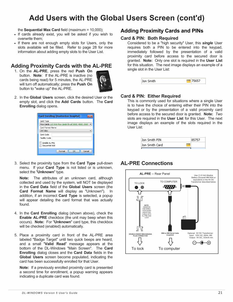
Adding Proximity Cards with the AL-PRE
1. On the AL-PRE, press the red Push On button. Note: If the AL-PRE is inactive (no cards being read) for 5 minutes, the AL-PRE will turn off automatically; press the Push On button to "wake up" the AL-PRE.
2. In the Global Users screen, click the desired User or the
empty slot, and click the Add Cards button. The Card Enrolling dialog opens.
3. Select the proximity type from the Card Type pull-down
menu. If your Card Type is not listed or is unknown, select the "Unknown" type.
Note: The attributes of an unknown card, although collected and used by the system, will NOT be displayed in the Card Data field of the Global Users screen (the Card Format Name will display as "Unknown"). In addition, if an incorrect Card Type is selected, a popup will appear detailing the card format that was actually found.
4. In the Card Enrolling dialog (shown above), check the
Enable AL-PRE checkbox (the unit may beep when this occurs). Note: For "Unknown" card type, this checkbox will be checked (enabled) automatically.
5. Place a proximity card in front of the AL-PRE area
labeled "Badge Target" until two quick beeps are heard, and a small "Valid Read" message appears at the bottom of the DL-Windows "Main Screen". The Card Enrolling dialog closes and the Card Data fields in the Global Users screen become populated, indicating the card has been successfully enrolled for that User.
Note: If a previously enrolled proximity card is presented a second time for enrollment, a popup warning appears indicating a duplicate card was found.
Adding Proximity Cards and PINs
Card & PIN: Both Required Considered to be a "high security" User, this single User
requires both a PIN to be entered into the keypad, immediately followed by the presentation of a valid proximity card before access to the secured door is granted. Note: Only one slot is required in the User List for this situation. The next image displays an example of a single slot in the User List:
Card & PIN: Either Required This is commonly used for situations where a single User
is to have the choice of entering either their PIN into the keypad or by the presentation of a valid proximity card before access to the secured door is granted. Note: Two slots are required in the User List for this User. The next image displays an example of the slots required in the User List:
AL-PRE Connections
AL-PRE -- Rear Panel
TO LOCK TO COMPUTER
DOUBLE-ENDED MINI BANANA PLUG CONNECTOR
DB9 to DB9 Serial Cable (supplied)
To lock
NOTE: OBSERVE
TAB DIREC-TION WHEN INSERTING CABLE INTO AL-PRE AND
LOCK
To computer
Optional: 9V DC Transformer: Input: 120V AC, 60Hz, 8W Output: 9V DC, 333mA min.
Use (1) 9 Volt Alkaline Battery (Duracell MN1604 or
equivalent) or the 9V DC Transformer described below.

22 DL-WINDOWS Vers ion 5 User 's Guide
Add Users with the Global Users Screen (cont'd) Adding Proximity Cards (Advanced) DL-Windows users can create their own proximity cards
based on user-defined proximity card data. This section is not necessarily required when adding
standard proximity cards, but is provided for advanced users who wish to define their own proximity format parameters. To use this screen successfully it is assumed you possess in-depth knowledge of the internal parameters of proximity cards. Using this screen likely requires the data sheet from the manufacturer or a deep understanding of the functionality of each field required for the specific card format. For example, parity bit attributes must be thoroughly understood before populating these fields.
Format Button (125kHz) When the Format button in the Card Enrolling dialog is
clicked, the Card Formats dialog opens displaying the proximity card format parameters for various manufacturer's pre-loaded proximity cards (such as CNT36 bit cards). For these pre-loaded card format data, the fields cannot be edited, as the parameters are displayed for reference only.
User Defined Card Format (125kHz) Open the Card Enrolling dialog and proceed as follows: In
the Card Type pull-down menu, select Prox Cards and click the Format button. In the Card Formats dialog that opens, as with the various manufacturer's pre-loaded proximity cards, the fields are initially inactive. However, the Copy button is available so that you can create and enter your own custom card format parameters. Note: Not all parameters are required for every card format.
Note: The Format Number is a field can be edited at your discretion but we recommend not to change it, as it is an internally designated number within DL-Windows.
Be sure to click the Save button to retain your custom card
formats. Unlike pre-loaded formats, User defined formats can be deleted as needed.
Format Button (13.56MHz) When the Format button in the Card Enrolling dialog is
clicked for locks with 13.5mHz readers (7000 and 8000 series), the Card Formats dialog opens (shown below) displaying the proximity card format parameters for iCLASS / FIPS proximity cards (e.g. HID 26 bit H10301 cards). For these card formats, card data can be copied and edited; see "Copy Button" below for instructions.
The above Card Formats screen is used to enter the
characteristics of the iCLASS data format definitions. Before using this Card Formats screen, it is assumed that you have an advanced level of knowledge regarding the data structure of iCLASS branded smart cards, and have been issued an iCLASS format data definition statement from HID Global. For more information, visit www.hidglobal.com.
Copy Button When clicked, all default parameters for the selected card
format will be displayed, but with the ability to be edited. Use this button for situations where you possess similar card format parameters, and wish to use most of them, while making minor changes. Note: The Card Format Name can be edited for your reference; if not edited, one will be assigned automatically.
The Copy button is also used for situations where you would like to enable certain features, such as Match Card Code Only or Match Facility Code Only, defined as follows:

DL-WINDOWS Vers ion 5 User 's Guide 23
• Match Card Code Only: Card Formats with this option selected will force programmed locks to ignore all other card parameters (e.g. Facility Code, Agency Code) and verify only the Card Code upon attempted access / presentation.
• Match Facility Code Only: Card Formats with this option selected will force programmed locks to ignore all other card parameters (e.g. Card Code, Agency Code) and verify only the Facility Code upon attempted access / presentation. WARNING: When checked, this is considered to be a VERY low security feature, as many different cards often may share the same Facility Code, and therefore the physical lock would then be unable to distinguish between multiple card holders.
User Defined Card Format (13.56MHz) Open the Card Enrolling dialog and proceed as follows: In
the Card Type pull-down menu, select Smart Cards. Then, in the Card Format Name pull-down menu, select User Defined_Smart and click the Format button.
In the Card Formats dialog that opens, as with the various
proximity card format parameters for iCLASS / FIPS cards, the fields are initially inactive. However, the Edit button is available so that you can create and enter your own custom card format parameters. Be aware that FIPS card formats do not have the User Defined option; therefore use the Copy button instead for creating custom FIPS formats. Note: All fields that are set with card format parameters will cause the reader to then verify the validity of each parameter entered. Not all parameters are required for every card format.
Note: The Format Number is a field that can be edited at your discretion but we recommend it not be changed, as it is an internally designated number within DL-Windows.
Add Users with the Global Users Screen (cont'd)

24 DL-WINDOWS Vers ion 5 User 's Guide
In the Global Users screen, one or multiple Users previously added to the User List can later be selected and "Removed", "Deleted" or "Disabled" as follows: "Removing" (Deactivating) Users In the Global Users screen, "Remove" is used to describe a User that continues to occupy a slot in the User List, but is "deactivated". The colored "box" in the Locks area of the Global Users screen is colored white, indicating the User's PIN number and/or proximity credential that was once "added" is now "removed" from the Lock Profile (removed from the physical lock's database), and therefore denying the User access through the protected door. Note: The word "Unassigned" is also used interchangeably with the word "Removed" throughout DL-Windows. Removing Users can be accomplished in either of two ways:
• In the Global Users screen, select desired User(s), then double-click on the desired colored "box" (Lock Profile) in the Locks area until the box color cycles back to white. White indicates the User has be "removed" from the selected Lock Profile.
--or-- • In the Global Users screen, select desired User(s), then
right-click the User(s) and select "Remove Users from All Locks" (all "boxes" [Lock Profiles] in the Locks area in the Account will be colored white, thus deactivating the selected Users). Alternatively, the other selection "Remove Users from Locks" can be used (selected "boxes" [Lock Profiles] in the Locks area will be colored white, thus deactivating the selected Users). The color codes for each rectangular "box" are as follows:
• White = User NOT added to the Lock Profile • Green = User added to the Lock Profile and enabled • Red = User added to the Lock Profile and disabled
Removing Proximity Cards from Locks See "Deleting Cards" below for complete information.
Deleting Users In the Global Users screen, "Delete" is used to describe a User that was completely erased from the User List (and therefore from the Account database). PIN and/or proximity credential information can be erased as desired. Proceed as follows:
• Right-click on the desired User(s) and click "Delete Users". Click OK to the popup warning, and Users will be completely erased from the User List (and therefore the Account database). For more information, see right click menu selections on page 27.
Deleting PINs from Locks This can be accomplished in one of two ways:
• The contents of the PIN field in the User List (or the PIN field in the User Information area) can be manually erased using the keyboard Backspace key.
Removing / Deleting / Disabling Users (Global Users Screen) --or-- • Right-click the desired User(s) and click either "Delete
PINs" (PIN is completely erased from the User List and therefore from the Account database) or "Delete All PINs" (ALL PINs that exist in the User List will be completely erased, and therefore completely erased from the Account database). For more information, see page 27.
Deleting Proximity Cards from Locks This can be accomplished in one of two ways: • Select desired proximity card User(s), then click the
Remove Card button in the Card Data area. Click OK to the popup warning, and proximity card data will be completely erased from the User List (and therefore the Account database) for the selected User(s).
--or-- • Right-click the desired User(s) and click either "Delete
Card" (proximity card data is completely erased from the User List and therefore from the Account database) or "Delete All Cards" (ALL proximity card data that exists in the User List will be completely erased, and therefore completely erased from the Account database). For more information, see page 27.
Deleting Users from Other Accounts
This option allows you to select an existing User in the User List, and then by using the right-click menu, delete that selected User from any other Account (or ALL other Accounts) existing in your DL-Windows in your database. For more information, see page 28.
Disabling Users In the Global Users screen, "Disable" is used to describe a User that continues to occupy a slot in the User List, but is intentionally "turned off" (the colored "box" in the Locks area of the Global Users screen is colored red, indicating the User is "disabled"). Although the PIN number and/or proximity credential exist in DL-Windows and also within the physical lock's database, upon attempted access to the physical lock, the lock will respond with a specific indication that the User is disabled and will not be granted access through the protected door. A common use for "disabling" a User is to purposely send the User (or Users) to the lock as "disabled", then later have a Schedule automatically enable the User at a specified time. This can be accomplished as follows:
• Select desired User(s), then double-click on desired colored "box" (Lock Profile) in the Locks area (green indicates "added") until the color cycles to red (indicating User is "disabled" in the Lock Profile). Note: Users can be disabled via scheduled events, see page 34 for a lit of Event Types.

DL-WINDOWS Vers ion 5 User 's Guide 25
Assign Users: Groups / Levels / Double Sided Access Groups Overview With many lock applications, it is convenient for large numbers of similar Users to be grouped together. Placing Users into Groups allows large numbers of Users to be controlled all at once --rather than individually-- saving time and effort. Groups can be controlled via Schedules, and a typical example involves enabling or disabling a Group at a certain time. In addition, a single User can be assigned to different Groups in different Lock Profiles within an Account. Groups may be enabled or disabled from the Lock Data screen, as desired. See page 30 for more information. Assigning User(s) to Groups Note: The User must be added to the Lock Profile before
performing this operation. In the Global Users screen, select desired User(s), then
click the Assign Groups button to display the Group Assignment dialog:
Notice how each Lock Profile is displayed with four
Groups available (GP1, GP2, etc.). As with the Locks "grid" in the Global Users screen, click the desired Group once to change the color from white to green:
• Green = User(s) assigned to the Group • White = User(s) NOT assigned to the Group
To save time, you can also use the check boxes located at the bottom of the dialog to add or remove User(s) to or from desired Groups (GP1, GP2, etc.) for ALL available Lock Profiles. Click Save to retain (or click Cancel to discard) your selections.
Note: If a User is "Removed" (a User that continues to occupy a slot in the User List, but is "deactivated") from a Lock Profile, their Group association will be lost.
Levels Overview (DL2800 and DL3000 models only) The Programming Level defines the range of keypad programming tasks a User is allowed to perform. For most locks, the higher the Level, the more keypad programming tasks the User is allowed (with the Master allowing ALL tasks
for all locks). Programming Levels are hierarchical (higher Levels are allowed to do anything the Levels below them can do). For example, if you are a Manager, you are allowed to do anything that Supervisors, Print-Only Users and Basic Users can do, in addition to those tasks allowed for Managers (Level 3). See "Programming Levels" on pages 6-7 for more details. Assigning Levels to User(s) Note: The User must be added to a DL2800 or DL3000
Lock Profile before performing this operation. In the Global Users screen, select desired User(s), then
click the Assign Levels button to display the Level Assignment dialog:
Notice how each Lock Profile is displayed with four
Levels available (LVL1, LVL2, etc.). As with the Locks "grid" in the Global Users screen, click the desired Level once to change the color from white to green:
• White = Level NOT assigned to User(s) • Green = Level assigned to User(s)
To save time, you can also use the check boxes located at the bottom of the dialog to add or remove Levels to or from desired Users (LVL1, LVL2, etc.) for ALL available Lock Profiles. Click Save to retain (or click Cancel to discard) your selections.
Note: If a User is "Removed" (a User that continues to occupy a slot in the User List, but is "deactivated") from a Lock Profile, their Level association will be lost.
Double Sided Access Overview DL5300, PDL5300 and NETWORXPANEL ("NETWX PNL") models only The above models are "double-sided" locks that allow control over either side of the protected door. Since "inside" or "outside" may not always apply, the words "Primary" (usually the "outside") and "Secondary" (usually the "inside" or "protected side" of the door) are used. Users can be assigned to Primary, Secondary or both (by default, Users are to assigned to "both" when added). Note: For the NETWORXPANEL, Primary = "Door 1" and Secondary = "Door 2".

26 DL-WINDOWS Vers ion 5 User 's Guide
Assign Users: Groups / Levels / Double Sided Access (cont'd) Assigning Users to a Side Note: The User must be added to the Lock Profile before
performing this operation. In the Global Users screen, select desired User(s), then
click the Double Sided Access button to display the Entry Side Selection dialog:
In the Entry Side Selection dialog shown above, each
Lock Profile is displayed with their two sides available (Primary or Secondary). Similar to the Locks "grid" in the Global Users screen, click once on the desired Side to change the color from green to white:
• Green = User(s) assigned to Side (Users are assigned to both sides by default)
• White = User(s) NOT assigned to Side (User MUST be assigned to at least one side)
To save time, you can use the check boxes located at the bottom of the dialog to add or remove User(s) to or from the desired Side for ALL available Lock Profiles. Click Save to retain (or click Cancel to discard) your selections. Note: If a User is "Removed" (a User that continues to occupy a slot in the User List, but is "deactivated") from a Lock Profile, their Primary or Secondary association will be lost and will be set back to "both".
SELECTING A RANGE OF USERS Multiple Users in the User List can be
selected by any of three methods: 1. CLICK & DRAG
Click to select the first User, hold down the mouse button and drag the mouse arrow down the list. Be aware that a maximum of 17 Users can be selected using this method. 2. SHIFT KEY Click to select the first User, press and hold the SHIFT key, then click the last User in the range. 3. CTRL Press and hold the CTRL key and click individual Users.
TIP

DL-WINDOWS Vers ion 5 User 's Guide 27
"Global Users" Screen - Right-Click Menu Right-clicking in the "User List" area of the Global Users screen opens a right-click menu; each item is detailed below.
Generate New User PIN - Random User Codes (PINs) may be generated for one or many Users. (Note: To avoid User Number conflicts, it is recommended to first assign specific User Codes to Users before selecting random User Code generation). A PIN Length menu will display; click to select the number of digits each generated User Code (PIN) will contain.
Generate All New User PINs - Random User Codes (PINs)
are generated for ALL Users listed in the Global Users screen User List. A PIN Length menu will display; click to select the number of digits each generated User Code (PIN) will contain. Note: Existing Codes (PINs) will be overwritten (card data will not change) and new PINs will be generated for every slot in the User List.
Delete PINs - Click to erase the User Code (PIN) from the
selected User(s); all other data will remain unchanged. A confirmation popup appears; click Yes to erase the User Code, click No to retain the User Code without making changes.
Delete All PINs - Click to erase ALL User Codes (PINs) from
ALL Users listed in the User List. A confirmation popup appears; click Yes to erase ALL User Codes, click No to retain ALL User Codes without making changes.
Delete Cards - Click to erase the existing proximity card data
from the selected User(s); all other data will remain un-changed. A confirmation popup appears; click Yes to erase the proximity card data, click No to retain the prox-imity card data without making changes.
Delete All Cards - Click to erase ALL existing proximity card
data from ALL Users listed in the User List. A confirma-tion popup appears; click Yes to erase ALL proximity card data, click No to retain ALL proximity card data without making changes.
Delete Users - Click to erase selected User(s) from the User
List, and therefore from the selected Account (Name, PIN, proximity card data, etc.). A confirmation popup appears;
click Yes to erase the User(s), click No to retain the User(s) without making changes.
Add Users to All Locks - Click to add the selected User(s)
to ALL existing Lock Profiles shown in the Locks area. A confirmation popup appears; click Yes to add User(s) to ALL Lock Profiles, click No to continue without making changes.
Add Users to Locks - Click to add
the selected User(s) to one or more of the Lock Profile(s) in the Account. The Add Users to Locks dialog appears listing ALL Lock Profiles within the Account; select desired Lock Profile(s) then click OK (or click Cancel to con-tinue without making changes).
Remove Users from All Locks - Click to erase the selected
User(s) from ALL existing Lock Profiles shown in the Locks area. A confirmation popup appears; click Yes to erase User(s) from ALL Lock Profiles, click No to continue without making changes.
Remove Users from Locks - Click to erase the selected
User(s) from one or more of the Lock Profile(s) in the Ac-count. A dialog appears listing ALL Lock Profiles within the Account; select desired Lock Profile(s) then click OK (or click Cancel to continue without making changes).
Add Users to All Accounts - (Administrators only). Make
this selection carefully. Click to add the selected User(s) to ALL LOCK PROFILES within ALL ACCOUNTS existing in the DL-Windows database. In addition, the selected User(s) will be ENABLED in ALL LOCK PROFILES in ALL ACCOUNTS (green in Lock area). A confirmation popup appears: Click Yes to add User(s); click No to continue without making changes. Note: If PINs or proximity card data for the selected User(s) conflicts with existing User(s), (e.g. a duplicate User, an existing Ambush Code, or a subset of an existing PIN), the conflict User(s) will NOT be added to the Account.
Right-Click Menu Highlight a name or names (or an empty Slot) and right-click to open the menu shown at right.

28 DL-WINDOWS Vers ion 5 User 's Guide
"Global Users" Screen - Right-Click Menu (cont'd) Add Users to Accounts - (Administrators only). Make this
selection carefully. Click to add the selected User(s) to ALL LOCK PROFILES within selected Accounts. In addi-tion, the selected User(s) will be ENABLED in ALL LOCK PROFILES in the selected Accounts (green in Lock area). A dialog appears listing ALL Accounts that exist within the DL-Windows database; select desired Ac-counts and click OK (or click Cancel without saving changes). Note: If PINs or proximity card data conflicts with another User, (e.g. a duplicate User, an existing Am-bush Code, or a subset of an existing PIN), the conflict User(s) will not be added to the Account.
Delete Users from All Accounts - (Administrators only).
Make this selection carefully. Click to erase the selected User(s) from ALL LOCK PROFILES within ALL AC-COUNTS existing in the DL-Windows database (Name, PIN, proximity card data, etc.). . A confirmation popup appears: Click Yes to erase User(s); click No to continue without making changes.
Delete Users from Accounts - (Administrators only).
Make this selection carefully. Click to erase the selected User(s) from ALL LOCK PROFILES within selected Ac-counts existing in the DL-Windows database (Name, PIN, proximity card data, etc.). A dialog appears listing ALL Accounts that exist within the DL-Windows database; se-lect desired Accounts and click OK (or click Cancel with-
out saving changes). Add User to Admin Screen - Click to add the selected User
(not multiple Users) to an available position within the Administrative Users screen. The Select Admin User dialog opens; from the pull-down list, select the position ("User Location"). Click OK to add the User to the se-lected position, click Cancel to exit without saving. Note: For Master Code position, PIN must be 6 digits in length, and cannot be a proximity credential.
Allow User to Issue Emergency Commands. - Provides
authority for a Basic User to initiate keypad Emergency Commands. See OI383 for more information regarding the wireless Networx system, its supported locks and fea-tures (including "Emergency Commands"). Note: When authority is provided to the User, a red siren icon appears next to the User's name in the User List.
Add a Block of Empty Slots to List - If all slots in the User
List are filled and you wish to add more Users, click this menu item to add a specified number of additional empty slots to the User List. The Add Blank Users dialog opens (shown below). Type a number into the number field (the available range will be specified in the dialog) and click OK to add the slots or click Cancel to exit with-out adding slots.

DL-WINDOWS Vers ion 5 User 's Guide 29
Right-Click Menu Highlight an Administrative User and right-click to open a menu containing the following items: Single-click in the User Name column highlights and selects one Administrative User. Generate New Code - Random User Codes (PINs) may be generated Administrative Users. (Note: To avoid User Number con-
flicts, it is recommended to first assign specific User Codes to Users before selecting random User Code generation). A PIN Length menu will display; click to select the number of digits the generated User Code (PIN) will contain. Note: Only "PIN Length 6" will be available for the Master Code.
Delete PIN - Click to erase the User Code (PIN) from the Administrative User; all other data will remain unchanged. A confir-mation popup appears; click Yes to erase the User Code, click No to retain the User Code without making changes.
Send User Back to Global Screen - Click to remove all Administrative User information, including the PIN from the Administrative Users screen and send it to the Global Users screen. An empty slot is required in the Global Users screen User List for this action.
Adding Users to the Administrative Users screen The Administrative Users screen is used assign Users to the administrative positions for ALL Lock Profiles within a single Account. The position of each Administrative User determines their Programming Levels and therefore defines the range of keypad programming tasks a User is allowed to perform. Administrative Users are special in that they can perform programming tasks that non-Administrative ("Basic") Users cannot perform (such as changing or adding new User Codes, etc.). Some of these Administrative Users are allowed more tasks than others, and the distinction between Users and their allowed tasks is known as a "Programming Level". (See the definition of "Programming Level" on page 6). Click the Administrative Users button on the Global Users screen to Access the Administrative Users dialog.
Name By default, this field is populated with the Admin User position description. As the First Name and Last Name fields are edited, this column will populate accordingly.
Admin Users The descriptive names in this col-umn cannot be edited, and are shown for referencing each Adminis-trative User position. See "Programming Levels" on page 6 for details.
Click a row in this column to high-light the Administrative User to be edited. In this example, the Master Code is highlighted, displaying the default User information in the screen, with the fields ready to be populated.
PIN Set each Administrative User PIN in this field. Master Codes must be 6 digits in length (no more, no less). If desired, this column can be hidden by pressing the Hide PINs button located in the Global Users screen.
User Information In this area the names and personal data of each Administrator can be cus-tomized as needed.
Custom Field Allows a customized field of up to 15 characters. This field is set in the Options screen and once changed remains identical for all Lock Profiles in all Accounts.
Comments Allows text up to 256 characters for each Administrative User.
Assign Groups Opens a new screen, allowing the assignment of the Administrative User to a specific Group within a Lock Profile.
Close Click to save your settings and exit the screen. Warning: This button always remains active, therefore pressing the keyboard Enter key is equivalent to clicking this button. In addition, clicking the "X" at the top right will save all changes made before closing the screen.
Emergency Users Displays the list of Emergency Users. See OI383 for more information regarding the wire-less Networx™ system and its supported features, including "Emergency Users" and "Emergency Commands".
Card Data Click Add Card to open the Card En-rolling dialog. Once a proximity cre-dential is successfully added, the fields will populate with proximity parameters (e.g. Card Code, Card Format Name and Facility Code). Up to 9 characters may be typed into the Card ID field, as desired. Click Remove Card to delete all proximity data. Note: AL-PRE will populate fields in this area automatically.

30 DL-WINDOWS Vers ion 5 User 's Guide
"Lock Data" Screen - Field and Button Definitions The Lock Data screen is an extension of the Global Users screen. It displays all enabled/disabled Users, their names, PINs, proximity card data, Group Associations, double-sided access rights and Programming Levels. Search by User name, communicate with your locks, set Group information, and print all lock data. Click the Lock button to access the Lock Data screen. The position of the User in the Global
Users screen does NOT indicate the actual User No. of the User in the Lock Data screen.
User Number = User Location = Location Number = Slot in lock
TIP
Communication Same as the Communication but-ton on the DL-Windows main screen. Allows the DL-Windows User to select Receive from Lock, Send to Lock, or Communicate with selected Networx Lock.
Group Enable (For all locks except the DL2800 and DL3000). Users that have been assigned a Group number can be enabled / disabled by checking or un-checking the asso-ciated box. Note: Group Enable data is not transferred by the AL-DTM3.
LVL1 LVL2 LVL3 LVL4 (Not shown; DL2800 / DL3000 only) Each non-Admin User can be associated with up to 4 Levels. Denoted by a check box for each Level; each check box will remain unchecked until the User's Level association is assigned in the Global Users screen.
Print Click to open a "Print Pre-view" screen, displaying all information in this screen. Click the "Printer" icon to send the request to your default printer.
Close Click to save your settings and exit the screen. Warning: This button always remains active, therefore pressing the keyboard Enter key is equivalent to clicking this button. In addition, clicking the "X" at the top right will save all changes made before closing the screen.
User Enabled Indicates the current status of each User. If the User is currently enabled, the check-box wil l be checked (unchecked for disabled).
GP1 GP2 GP3 GP4 (User Group Association). Each User can be associated with up to 4 Groups. Denoted by a check box for each Group; each check box will remain unchecked until the User's Group associa-tion is assigned in the Global Users screen.
Card Type Proximity credential information dis-played for each proximity User. The Card Type specifies the format of the card being used (e.g. CNT 37 bit).
Card Code Proximity creden-tial information displayed for each Prox User. The Card Code is the "serial" number or "PIN" number embedded within the card data parameters.
Facility Code Proximity credential information displayed for each Prox User. The Facility Code (also known as a "site code", is a unique number common to all cards in a particu-lar set.
PIN Also called User Codes, PINs are numbers the User presses into the lock keypad. In DL-Windows, PINs are entered via the Global Users screen. Adminis-trators can hide this column by clicking the Hide Pins button. This column is hidden for all non-Administrator DL-W i n d o w s U s e r s (Operators).
Card ID Used to physically identify a proximity card that has been assigned by a DL-Windows User.
User Name In this field, the First and Last Name entered in the Global Users screen is displayed. The Name listed in the Lock Data screen will appear on all log entries. The default labels (such as "Supervisor 1") that appear in the User Name column when a new Lock Profile is created are for reference only. As Users are as-signed to each User Num-ber "slots", the User Name will appear in place of the default values shown.
User No. User Numbers are significant within each individual lock only. For example, many locks can hold up to 5000 Users in its programming memory. This memory can be thought of as simply a numbered list. Each entry in the list is represented by this User Number. Therefore, where a User is located in this list--their User Location--is a commonly used descrip-tion of their User Number. Knowing a User Number will specify the associated Programming Level, and will in turn indicate a User's programming abilities. See the Terminology section for more information regarding Program-ming Levels.
DS Acc. Indicates the User's double-sided access rights. P = Primary Side only; S = Secon-dary Side only; B = Both Primary and Sec-ondary Sides (always set to "B" for all Admin-istrative Users and Basic Users unless changed in the Global Users screen).
Type user name to search Type the User Name to be searched. For example, enter "Bob". All names with "Bob" in the User Name will display.

DL-WINDOWS Vers ion 5 User 's Guide 31
"Schedules" Screen - Field and Button Definitions This screen consists of two parts--the Time Zones area (top) and the Schedule Entry area (bottom). The Time Zones area is used to program the time the event(s) will occur, and the Schedule Entry area is used to create events that can be linked to the times created in the Time Zones area. Use this screen to create schedules where your lock can unlock at a certain times, enable Groups, disable Users, and set "windows of opportunity" (in other words, "windows of time") for lock actions. Schedules may be saved and imported for use with other Lock Profiles and Accounts. Click the Schedules button to access the Schedules screen.
^ (Minimize) Time Zones - Allows you to minimize the Time Zones area.
Time Zone # - Use the pull-down to select the desired Time Zone. Use Add button to add more Time Zones (250 maximum allowed).
Add - Click to add additional Time Zones (250 maximum). Each added Time Zone will be available from the Time Zone # pull-down.
Delete - Click to delete added Time Zones. At least one Time Zone must be available (the last Time Zone cannot be deleted).
Print Time Zones - Click to open a "Print Preview" screen, displaying every Time Zone created. Click the "Printer" icon to send the request to your default printer.
Day - Displays day of the week (for reference only). Note: All = Sunday - Saturday.
Start - For the selected day (row), set the time you wish to begin the Schedule (in other words, the starting time for the Event). Double-click desired start time to enable pull-down selections. At each pull-down, set the hour / minute / AM / PM accordingly. Pull-down fields may be cleared and edited manually; leave blank for open-ended ("single-ended") schedules (see page 35 for more information).
Stop - For the selected day (row), set the time you wish to end the Schedule (in other words, the stop time for the Event). Double-click desired stop time to enable pull-down selections. At each pull down, set the hour / minute / AM / PM accordingly. Pull-down fields may be cleared and edited manually; leave blank for open-ended ("single-ended") schedules (see page 35 for more information).
Month - For the selected day (row), set the month of the year (default = all months). Double-click to enable pull-down selection of desired month.
Day of Month - For the selected day (row), set the day of month (default = all). Double-click to enable pull-down selection of desired day of month (1 - 31).
Enable - Denoted by check box, click to enable selected day (row). Default = Sun. - Sat. Enable row "All" for full week 7-day Time Zones. Right-click the Enable column and a small popup list appears with additional selections (see next section)
^ (Minimize) Schedule Entry - Allows you to minimize the Schedule Entry area.
Add - Click to add additional Event Numbers (494 maximum).
Clear Entry - Click to clear contents of selected Event Number (row).
Clear All - Click to clear contents of all scheduled entries. Print Schedules - Click to open a "Print Preview" screen, displaying every scheduled
entries created. Click the "Printer" icon to send the request to your default printer.
Save Schedule - Opens a dialog to save all attributes of the Schedule (all Time Zones and all Events). In addition, Schedules can be saved for all Accounts (see page 34 for more information).
Import Schedule - Opens a dialog to import previously saved Schedules (see page 34 for more information).
Event Number - Event Numbers denote each scheduled Event. These numbers are displayed for reference only (maximum 494 Events).
Description - Type a short summary of each scheduled Event (up to 40 characters). User / Group - Double-click to show pull-down, then select the Group or User
Number associated with the scheduled Event (if required). If the Event is associated with a Group, valid entries are 1 to 4. If the Event is associated with a User Number, valid entries are 2 to 5000 depending on lock type (model). Selection will determine Events available.
Event - Double-click to show pull-down of available Events (lock actions). Options change depending upon the selection made in User / Group, if any. The Events are: (Blank), Unlock, Lock, Disable Group, Enable Group, Disable User, Enable User, Passage Mode by Grp1-Open Window, Relay Activation by Grp1-Open Window and Enable Group 4 by Grp1-Open Window.
Time Zone - Double-click to show pull-down of available Time Zone numbers. Use this field to link Events (lock actions) to available Time Zones.
Switch to Sched. View - Combines the Time Zone area with the scheduled Events. Opens Schedule View screen displaying a read-only view of full schedules.
Close - Saves all changes and exits the Schedules screen.

32 DL-WINDOWS Vers ion 5 User 's Guide
"Schedules" Screen - Right-Click Menu
Right-Click Menu Right-click on Start time or Stop time to view the following options:
• Clear Start / Stop Time - When option is selected for highlighted Start time, Start time will be cleared (blank). When option is selected for highlighted Stop time, Stop time will be cleared (blank).
• Clear All Start / Stop Times -
When option is selected for any Start time, ALL Start times will be cleared (blank). When option is selected for any Stop time, ALL Stop times will be cleared (blank).
• Set All As Current Start / Stop - When option is selected
for highlighted Start time, ALL existing Start times will then reflect the highlighted Start time. When option is selected for highlighted Stop time, ALL existing Stop times will then reflect the highlighted Stop time.
Right-Click Menu Right-click on Enable column to view various day-to-day Enable configurations, as shown at right:

DL-WINDOWS Vers ion 5 User 's Guide 33
Schedules Overview Schedules consist of two main parts: The Event (the action the lock will perform) and the Time Zone (the time/day the Event will occur).
It is important to conceptualize your complete Schedule first. In other words, try to write a simple description of what you want the lock to do, and when. For example:
"I want the lock on my office door to unlock at 9 AM and re-lock when I leave my office at 5 PM. I want this to happen every day I am at the office, Monday through Friday."
The above sentence is a typical example of a Schedule; it contains an Event ("unlock") and a Time Zone (Monday - Friday, 9 AM to 5 PM).
Begin by creating the Time Zone. Creating Time Zones In the Time Zone area, select the day(s) and time(s) you want the Events in your Schedule to occur.
1. Highlight / select the first day of the week your intended scheduled Event will occur (selection highlighted in blue). For example, click in the Monday row. Select day of week ALL to utilize a 7-day Schedule.
2. For the day "row" selected, double-click the Start time field. Use each pull-down to select the hour, minute and AM/PM for your Start time accordingly (the time your intended scheduled Event will begin). Pull down fields may be cleared and edited manually; leave blank for open-ended ("single-ended") schedules (see page 35 for more information).
3. For the day "row" selected, double-click the Stop time field. Use each pull-down to select the hour, minute and AM/PM for your Stop time accordingly (the time your intended scheduled Event will end). Pull down fields may be cleared and edited manually; leave blank for open-ended ("single-ended") schedules (see page 35 for more information).
4. If necessary, set Month and Day of Month for your intended scheduled Event. Leave default setting (All) unless your schedule requires a specific month and/or specific day.
5. In the Enable column, click to add a check to the check box to enable that day for your intended scheduled Event.
6. Repeat above steps for all days required in your Schedule.
Note: When multiple Events occur on the same day
but at different times, multiple Times Zones are required. Click Add in Time Zone area (top) and repeat steps above to create additional Time Zones.
Creating Time Zones and Events in the Schedule Screen
Creating Events In the Schedule Entry area, select Events and Users/Groups (if required), then link to Time Zones.
1. For the first Event, in the Description field, type a brief summary (40 characters maximum) describing the Event (lock action) to occur.
2. If necessary, double-click the User/Group field, and use the pull-down to select the User or Group associated with your intended scheduled Event. Select 1-4 for enabling / disabling a Group; select 2-5000 for enabling / disabling a User (depending on lock type). Selection will determine Events available in the next step (Event column). Note: For "Grp1-Open Window Events", User/Group selection is not required.
3. Double-click the Event field and in the pull-down, select the desired Event. Events available are determined by the previous selection made in step 2, if any.
4. Double-click the Time Zone field and in the pull-down, select the desired Time Zone to which your Event will be linked.
5. Repeat steps 1-4 for other Events, if more Events are required than are available, click the Add button located in the Schedule Entry area.
Note: When adding data to the "User / Group", "Event" and "Time Zone" columns, all three columns must be completed at one time. A red box will surround the Event "row" if the Event is incomplete.
Switch to Schedule View Upon completion of Schedule programming, click the Switch to Sched View button to verify the full details of your Schedule. A popup appears, "Are you sure you want to overwrite all the previous data?". Click Yes in the popup and continue to the Schedule View screen to view all
IMPORTANT: Time Zones are "Global" to your Account, and are shared between all of the Lock Profiles in the Account. Events are NOT shared between Lock Profiles. Full Schedules (Time Zones and Events) may be shared between Lock Profiles and even other Accounts by using the Save / Import feature.
Most Schedules are "double-ended", with one end being the Start time (begins the
Event) and the other end the Stop time (performs the opposite of the Start time Event). For
example, with an unlock Schedule from 9 AM to 5 PM, the Start time begins the "unlock" Event, and remains unlocked until the End time performs its opposite ("lock"). Notice that a second "lock" Event is NOT required.
TIP

34 DL-WINDOWS Vers ion 5 User 's Guide
attributes of your Schedule (Time Zones and Events combined). For more information about the Schedule View screen, see page 33 and page 37. Saving and Importing Schedules Since Events are not shared between Lock Profiles, and are therefore designated to the Lock Profile in which the Schedule was created, full Schedules (Times Zones and Events) may be shared between Lock Profiles by using the Save Schedule / Import Schedule features. Note: Full Schedules may also be saved and available for importing into Lock Profiles located in other Accounts. Save Schedule 1. Once Time Zones and Events have been created in the
Lock Profile(s), click Save Schedule. The Save
Creating Time Zones and Events in the Schedule Screen (cont'd) Schedule dialog opens.
2. In the Schedule Description field, type a brief summary describing your Schedule (40 characters maximum).
3. If desired, select the Save for all Accounts checkbox to allow the Schedule to be imported into ANY other Lock Profile in ANY other Account. Click OK to save your Schedule.
Import Schedule 1. Open desired Account and Lock Profile into which you
would like to import the Schedule. 2. Click the Schedules button located on the toolbar of the
DL-Windows "Main Screen". 3. C l ick the Impor t
Schedule button. The Import Schedule dialog opens.
4. In the pull-down, select the previously saved Schedule and click OK. All attributes of the Schedule will be imported into the Lock Profile (all Time Zones and all Events).
Editing Saved Schedules
Existing Schedules may be edited and saved again, as required. 1. In the Lock Profile where the Schedule originated,
make the desired changes to the Schedule, then click the Save Schedule button.
2. In the dialog that appears, the previously saved Schedule will be listed in the Saved Schedules list. Click the previously saved Schedule Description from the list, and click OK.
3. A popup will appear indicating the schedule already exists; click OK to overwrite and replace the existing Schedule. Note: Be sure to re-import Schedules in other Lock Profiles, as necessary. Note: The "Save for all Accounts" checkbox may be checked (enabled), as desired.
Note: If Save for all Accounts checkbox was not selected previously, by using the previous step you can go back and change it. To Delete a Schedule: In the Save Schedule dialog, select the Schedule to be deleted and click the Delete button.
Event Types (Defined)
Unlock – Device unlocks at programmed time. Lock – Device locks at programmed time. Disable Group – All Users within specified Group become
disabled at the programmed time. Enable Group - All Users within specified Group become
enabled at the programmed time. Disable User – Specified User is disabled at programmed
time. Enable User – Specified User is enabled at programmed
time. Passage Mode by Group 1–Open Window – Places
device into Passage Mode (unlocked state) when a member of Group 1 enters their PIN (or other valid credential). The Start time opens the timeframe ("window of opportunity") where the Group 1 member can enter their PIN to enable Passage Mode. The Stop Time ends the timeframe (closes the "window").
Note: If a Group 1 member has successfully placed the device into Passage Mode, the device will NOT exit Passage Mode automatically. Be sure to lock manually or schedule a single-ended Lock event.
Relay Activation by Group 1–Open Window – Sets a timeframe ("window of opportunity") where if a Group 1 member enters their PIN (or other valid credential), a relay activation is triggered. A relay is commonly used to arm and diarm burgalry alarm control panels.
Enable Group 4 by Group 1–Open Window – Sets a timeframe ("window of opportunity") where if a Group 1 member enters their User Code (PIN) , all members of Group 4 will become enabled.
Note: Group 4 will remain enabled if a Group 1 member has entered their PIN (or other valid credential) within the specified time. Be sure to disable Group 4 manually, or schedule a single-ended Disable Group Event.

DL-WINDOWS Vers ion 5 User 's Guide 35
Single-Ended Schedules Though most schedules are double-ended (containing both Start and Stop times), single-ended Schedules that contain a Start time only (or a Stop time only) may be required ("single-ended" may also be referred to as "open-ended"). Example The use of a single-ended Schedule can be used to safeguard a "Passage Mode by Group 1– Open Window" Event. By using a single-ended lock Event, a "safeguard" will be in place to ensure Passage Mode is disabled (locking the device) at the same time every day. The above screen displays an example of the "Passage Mode by Group 1–Open Window" as shown from the Schedule View screen. As defined earlier, Passage Mode by Group 1–Open Window places the device into Passage Mode (unlocked state) when a member of Group 1 enters their PIN (or other valid credential). The Start time opens the timeframe ("window of opportunity") where the Group 1 member can enter their PIN to enable Passage Mode. The Stop time ends the timeframe (closes the "window"). Since the device will not exit Passage Mode automatically, you must add a safeguard by adding single-ended lock Event. To begin, first add a new Time Zone (e.g. "Time Zone 2"), then clear the Stop times for the days the Schedule will be triggered. Do this via right-click option or by manually clearing the Stop time numerals. Next, change all required Start times to a time that the device must be locked ("safeguard" time). As shown below, right click and select "Set All As Current Start" (all set to 5 PM):
Schedules...In More Detail Next, create new "safeguard" Event (set the Event to "Lock", and set the Time Zone to "Time Zone 2"). The Schedule View screen should look similar to this: Summary: As shown above in the Schedule View screen, if the lock remains in Passage Mode at 5 PM, the device will re-lock indefinitely.

36 DL-WINDOWS Vers ion 5 User 's Guide
Holiday Schedule (Suppression) Similar to single-ended schedules, a single Event may be programmed for a holiday to suppress normal Schedule activity. Example You are currently using a double-ended Schedule where, Monday through Friday, your device unlocks every day at 7 AM and re-locks at 5:30 PM. Shown below is an example of this unlock schedule in the Schedule View screen: As most businesses close on Christmas day every year, you must suppress the unlock Schedule by adding a single "lock" Event for that day ("25") and that month ("December"). Note: "Lock" Events always take precedence over "unlock" Events, therefore when both are programmed for the same time, the "unlock" Event will be suppressed.
To begin, first add a new Time Zone (e.g. "Time Zone 2"), then in the "All" row, check the Enable check box and also be sure to clear its Stop time. Do this via right-click option ("Clear Stop Time") or by manually clearing the Stop time. IMPORTANT: Start time MUST be the same as the Start time of the Event you wish to suppress! In this example, 7 AM was the Start time, therefore, in Time Zone 2, 7 AM must ALSO be the Start time. Next, change Month pull-down to "December" and Day of Month pull-down to "25".
Next, create new Holiday suppression Event (set the Event to "Lock", and set the Time Zone to "Time Zone 2"). The Schedule View screen should look similar to this: Summary: As shown above in the Schedule View screen, the normal unlock Schedule for 7 AM is suppressed by the addition of the December 25th Lock Event for 7 AM, thus the lock remains in locked every year on that date, at that time. This type of Schedule can be used for all types of holidays; however, for holidays where the Day of the Month varies from year to year (such as the American Thanksgiving holiday), this date MUST be manually changed from year to year.
Schedules...In More Detail (cont'd)

DL-WINDOWS Vers ion 5 User 's Guide 37
The Schedule View screen combines the Time Zones with the scheduled Events from the Schedules screen. The Schedule View screen is a read-only screen that is designed as an overview of programmed Schedules. In addition, the Schedule View screen becomes populated when schedules are received from locks. Click the Schedule View button to access the Schedule View screen.
"Schedule View" Screen - Field and Button Definitions
Event Number Event Numbers denote each scheduled Event. This number is displayed for reference only. Note: Unlike the Schedule Entry area of the Schedules screen, all Events, including Stop or End Events, are shown.
Day of Month Day of month of each Event programmed in the Schedule screen.
Month Month of each Event programmed in the Schedule screen.
User or Group The User or Group number associated with each Event programmed in the Schedule screen. Note: Group 1 not displayed for Open / Close window Events Day of Week
Day of the week of each Event programmed in the Schedule screen. Will be condensed when optimal (e. g. "Mon - Fri").
Clear All Clears ALL Time Zone and Event data from the Schedule View screen.
Print Click to open a "Print Preview" screen, displaying all information in the Schedule View screen. Click the "Printer" icon to send the request to your default printer.
Time The Start time and Stop time of each Event programmed in the Schedule screen.
Close Click to close the Schedule View screen.
Event The Events programmed in the Schedule screen. Note: Unlike the Schedule Entry area of the Schedules screen, all Events, including Stop or End Events, are shown.
When keypad programmed Schedules are uploaded (received) into DL-
Windows, the Schedules can ONLY be viewed through the Schedule View screen, not
the Schedule screen. Therefore, before any downloading (sending data to lock) can be performed from the Schedule View screen, select Send Schedule from Schedule View option in the Options screen.
TIP

38 DL-WINDOWS Vers ion 5 User 's Guide
Lock ID Lock ID will be between 1– 2000; the number is designated by the position within the Account. Note: When a new Lock Profile is added, the Lock ID number is added based on its order within the Account. When used with the AL-DTM3, this is the number the AL-DTM3 will use to identify itself to the physical lock, insuring that the proper data inside the AL-DTM3 will be matched to the correct lock.
Pass Time In Seconds The duration in seconds that the physical lock will remain unlocked after a valid credential has been entered (3, 10 & 15 seconds).
Entry Delay in Seconds Delays door entry (access) after a valid credential has been presented (0, 5, 15 and 45 seconds).
Lockout # of Attempts The maximum number of invalid entry attempts (with wrong PIN) the lock will allow before it enters "lockout mode", where the lock refuses to recognize any PIN entry. The lock will shut down for the period programmed in the Lockout Time in Seconds field, which follows (1-9).
Lockout Time in Seconds The duration of time the lock refuses to recognize any PIN after the maximum number of invalid entry attempts (with wrong PIN) has been reached (1-60 seconds).
Lock Responds to Emergency Commands Users are Disabled during Lockdown See OI383 for more information regarding the wireless Networx system and its supported features, including "Emergency Commands" and "Lockdown".
Group 2 Toggles Passage Mode If checked, any valid credential from a Group 2 member has the ability to toggle Passage Mode (lock is unlocked). Caution! The consequences of accidentally selecting this option can cause a security breach! (Not applicable to the DL2800 / DL3000. Note: May not be selected with Group 2 Enables and 3 Disables Passage Mode).
Group 2 Enables and 3 Disables Passage Mode If checked, any valid credential from a Group 2 member places the lock in Passage Mode (lock is unlocked). In addition, any valid credential from a Group 3 member will take the lock out of Passage Mode. Caution! The consequences of accidentally selecting this option can cause a security breach! (Not applicable to the DL2800 / DL3000. Note: May not be selected with Group 2 Toggles Passage Mode).
One Time Entry for Group 3 Users If checked, the presentation of a valid credential from a Group 3 member will unlock the lock one time only; then that credential will become disabled. (Not applicable to the DL2800 / DL3000).
Star Key as Enter Key If checked, all PINs entered must be followed by the keypad "star" key.
"Features" Screen - Options tab The Features screen is used to program various lock options and a variety of programmable Features. In the Options tab, you can set door actions, Group entry modes, lock sounder, Daylight Saving Time and Door Monitoring functions. The screen shown below is from a PDL6200 lock type (model), and was created to show as many options as possible. Available options will vary with lock type. Click the Features button to access the Features screen.
Disable Sounder Disable the lock sounder to enable silent operation (not available on all lock models).
Enable Star Key as Doorbell Check to allow the "star" key to act as a doorbell. Sounder must be enabled for doorbell operation (not available on all lock models).
Enable Entry Sounder Check to enable sounder to activate upon each valid credential or Remote Input activation (not available on all lock models).
Custom Daylight Savings Time (Pull-Down) Most lock models will adjust for Daylight Saving Time automatically, and therefore will reflect this option (enabled by default). When the Daylight Saving Time adjustment is not required, from the pull-down select Daylight Savings Disabled. For some lock types (e.g. PDL3000), 23 pre-set DST adjustments are available as well as custom Daylight Saving Time settings. For these models, when the DST adjustment is not required, from pull-down select No DST Adjust. Note: For DL2800 and DL3000, when DST adjustment is not required, uncheck the Daylight Savings Time checkbox.
Custom Daylight Saving Time (button) Opens the adjustable Daylight Saving Time settings dialog. See pages 38-39 for more information.
Enable Door Ajar Monitoring If checked, door will be monitored for "Door Ajar" occurrences. A "Door Ajar" occurs when the protected door is found to be left open after a specified period of time. Requires remote input used for door monitoring. Enabling this feature disables the Remote tab in this Features screen. Not available for all lock models. Note: For use with door position contacts.
Door Ajar Trip Time in Seconds Select from pull-down the delay time in seconds before a Door Ajar occurrence is monitored. Not available for all lock models. Note: For use with door position contacts.
Use Sounder on Door Ajar If checked, the lock sounder will trigger an audible warning upon a valid Door Ajar occurrence. Not available for all lock models. Note: For use with door position contacts.
Forced Door Detection If checked, sounder will trigger upon "door open" without prior valid credential entry. Not available for all lock models. Note: For use with door position contacts.
Close Click to close this screen.

DL-WINDOWS Vers ion 5 User 's Guide 39
"Features" Screen - Options tab (cont'd)
Click buttons to scroll through the months
Click any day in the selected month to set
Current date is
highlighted. All Daylight Saving Time adjustments
will take place at 2 AM on the day selected. Daylight Saving Time "start" and
Daylight Saving Time "end" will be logged accordingly.
TIP Click the Custom Daylight Savings Time button to open the Adjustable Daylight Savings Time dialog.
Start Month/Day The default Start date based upon the DST law enacted for 2007 in the USA (Second Sun-day in March).
Start Month/Day (field) DST Start Month/Day/Year will adjust automatically every year. Click calen-dar icon to select custom DST Start. Field may be manually edited (the format MM/DD/YYYY must be main-tained).
Set USA Default - Click to revert the Start Month/Day and End Month/Day back to their default dates. In the United States, the start date is the second Sun-day in March; the end date is the first Sunday in November.
OK Click to save changes and exit.
Cancel Click to exit without saving changes.
Button Click icon and calendar will appear.
End Month/Day (field) DST End Month/Day/Year will adjust automatically every year. Click calendar to select custom DST End. Field may be manually edited (the format MM/DD/YYYY must be maintained).
End Month/Day The default End date based upon the DST law enacted for 2007 in the USA (First Sunday in November).
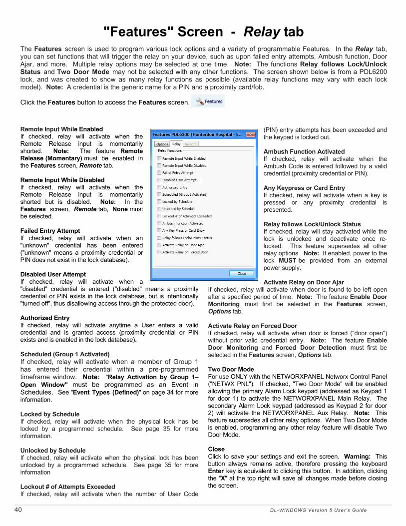
40 DL-WINDOWS Vers ion 5 User 's Guide
"Features" Screen - Relay tab The Features screen is used to program various lock options and a variety of programmable Features. In the Relay tab, you can set functions that will trigger the relay on your device, such as upon failed entry attempts, Ambush function, Door Ajar, and more. Multiple relay options may be selected at one time. Note: The functions Relay follows Lock/Unlock Status and Two Door Mode may not be selected with any other functions. The screen shown below is from a PDL6200 lock, and was created to show as many relay functions as possible (available relay functions may vary with each lock model). Note: A credential is the generic name for a PIN and a proximity card/fob. Click the Features button to access the Features screen.
Remote Input While Enabled If checked, relay will activate when the Remote Release input is momentarily shorted. Note: The feature Remote Release (Momentary) must be enabled in the Features screen, Remote tab. Remote Input While Disabled If checked, relay will activate when the Remote Release input is momentarily shorted but is disabled. Note: In the Features screen, Remote tab, None must be selected. Failed Entry Attempt If checked, relay will activate when an "unknown" credential has been entered ("unknown" means a proximity credential or PIN does not exist in the lock database). Disabled User Attempt If checked, relay will activate when a "disabled" credential is entered ("disabled" means a proximity credential or PIN exists in the lock database, but is intentionally "turned off", thus disallowing access through the protected door). Authorized Entry If checked, relay will activate anytime a User enters a valid credential and is granted access (proximity credential or PIN exists and is enabled in the lock database). Scheduled (Group 1 Activated) If checked, relay will activate when a member of Group 1 has entered their credential within a pre-programmed timeframe window. Note: "Relay Activation by Group 1–Open Window" must be programmed as an Event in Schedules. See "Event Types (Defined)" on page 34 for more information. Locked by Schedule If checked, relay will activate when the physical lock has be locked by a programmed schedule. See page 35 for more information. Unlocked by Schedule If checked, relay will activate when the physical lock has been unlocked by a programmed schedule. See page 35 for more information Lockout # of Attempts Exceeded If checked, relay will activate when the number of User Code
(PIN) entry attempts has been exceeded and the keypad is locked out. Ambush Function Activated If checked, relay will activate when the Ambush Code is entered followed by a valid credential (proximity credential or PIN). Any Keypress or Card Entry If checked, relay will activate when a key is pressed or any proximity credential is presented. Relay follows Lock/Unlock Status If checked, relay will stay activated while the lock is unlocked and deactivate once re-locked. This feature supersedes all other relay options. Note: If enabled, power to the lock MUST be provided from an external power supply. Activate Relay on Door Ajar
If checked, relay will activate when door is found to be left open after a specified period of time. Note: The feature Enable Door Monitoring must first be selected in the Features screen, Options tab. Activate Relay on Forced Door If checked, relay will activate when door is forced ("door open") without prior valid credential entry. Note: The feature Enable Door Monitoring and Forced Door Detection must first be selected in the Features screen, Options tab. Two Door Mode For use ONLY with the NETWORXPANEL Networx Control Panel ("NETWX PNL"). If checked, "Two Door Mode" will be enabled allowing the primary Alarm Lock keypad (addressed as Keypad 1 for door 1) to activate the NETWORXPANEL Main Relay. The secondary Alarm Lock keypad (addressed as Keypad 2 for door 2) will activate the NETWORXPANEL Aux Relay. Note: This feature supersedes all other relay options. When Two Door Mode is enabled, programming any other relay feature will disable Two Door Mode. Close Click to save your settings and exit the screen. Warning: This button always remains active, therefore pressing the keyboard Enter key is equivalent to clicking this button. In addition, clicking the "X" at the top right will save all changes made before closing the screen.

DL-WINDOWS Vers ion 5 User 's Guide 41
The Features screen is used to program various lock options and a variety of programmable Features. In the Remote tab, you can program the functionality of the Remote Input on your device (the Remote Input is, in most cases, the two white wires located inside the rear of the "protected side" housing). Only one Remote Input function may be selected at any one time. Note: Some features require the Remote Input have a maintained closure, therefore the use of an external power supply will be required. Click the Features button to access the Features screen.
"Features" Screen - Remote tab
None If checked, Remote Input is disabled (Remote Input inactive). Remote Release (Momentary) If checked, Remote Input is enabled for the duration of the Pass Time and will cause the door to unlock upon momentarily short. Remote Toggles Passage Mode If checked, Remote Input will toggle Passage Mode. Each momentary short of the Remote Input will cause the device to switch between locked and unlocked states. Remote Disables Lock If checked, Remote Input disables the lock while a short is maintained (held closed) across remote input. Therefore, if a switch is used for the remote input, as long as the switch is closed the lock will be disabled and its state cannot be changed. As long as the switch is open, the lock will be enabled. Note: If enabled, power to the lock MUST be supplied by an external power supply. Forced Lock Follows Remote If checked, the lock will lock when a short is maintained (held closed) across the remote input. Therefore, if a
switch is used for the remote input, as long as the switch is closed the lock will be locked and its state cannot be changed. Note: If enabled, power to the lock MUST be supplied by an external power supply. Forced Unlock Follows Remote If checked, the lock will unlock when a short is maintained (held closed) across the Remote Input. Therefore, if a switch is used for the Remote input, as long as the switch is closed the lock will be unlocked and its state cannot be changed. Note: If enabled, power to the lock MUST be supplied by an external power supply. Remote Puts Lock in PC Comm Mode If checked, the Remote Input will act as User 298 (or keypad Function 58), i.e. will place the device into PC Communication Mode. Function not available for Networx lock types. Close Click to save your settings and exit the screen. Warning: This button always remains active, therefore pressing the keyboard Enter key is equivalent to clicking this button. In addition, clicking the "X" at the top right will save all changes made before closing the screen.
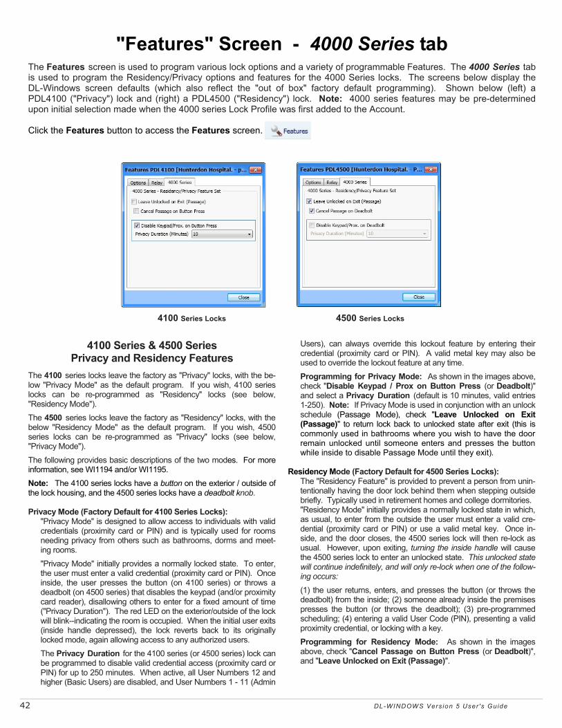
42 DL-WINDOWS Vers ion 5 User 's Guide
4100 Series & 4500 Series Privacy and Residency Features
The 4100 series locks leave the factory as "Privacy" locks, with the be-low "Privacy Mode" as the default program. If you wish, 4100 series locks can be re-programmed as "Residency" locks (see below, "Residency Mode").
The 4500 series locks leave the factory as "Residency" locks, with the below "Residency Mode" as the default program. If you wish, 4500 series locks can be re-programmed as "Privacy" locks (see below, "Privacy Mode").
The following provides basic descriptions of the two modes. For more information, see WI1194 and/or WI1195.
Note: The 4100 series locks have a button on the exterior / outside of the lock housing, and the 4500 series locks have a deadbolt knob. Privacy Mode (Factory Default for 4100 Series Locks):
"Privacy Mode" is designed to allow access to individuals with valid credentials (proximity card or PIN) and is typically used for rooms needing privacy from others such as bathrooms, dorms and meet-ing rooms.
"Privacy Mode" initially provides a normally locked state. To enter, the user must enter a valid credential (proximity card or PIN). Once inside, the user presses the button (on 4100 series) or throws a deadbolt (on 4500 series) that disables the keypad (and/or proximity card reader), disallowing others to enter for a fixed amount of time ("Privacy Duration"). The red LED on the exterior/outside of the lock will blink--indicating the room is occupied. When the initial user exits (inside handle depressed), the lock reverts back to its originally locked mode, again allowing access to any authorized users.
The Privacy Duration for the 4100 series (or 4500 series) lock can be programmed to disable valid credential access (proximity card or PIN) for up to 250 minutes. When active, all User Numbers 12 and higher (Basic Users) are disabled, and User Numbers 1 - 11 (Admin
Users), can always override this lockout feature by entering their credential (proximity card or PIN). A valid metal key may also be used to override the lockout feature at any time.
Programming for Privacy Mode: As shown in the images above, check "Disable Keypad / Prox on Button Press (or Deadbolt)" and select a Privacy Duration (default is 10 minutes, valid entries 1-250). Note: If Privacy Mode is used in conjunction with an unlock schedule (Passage Mode), check "Leave Unlocked on Exit (Passage)" to return lock back to unlocked state after exit (this is commonly used in bathrooms where you wish to have the door remain unlocked until someone enters and presses the button while inside to disable Passage Mode until they exit).
Residency Mode (Factory Default for 4500 Series Locks): The "Residency Feature" is provided to prevent a person from unin-tentionally having the door lock behind them when stepping outside briefly. Typically used in retirement homes and college dormitories. "Residency Mode" initially provides a normally locked state in which, as usual, to enter from the outside the user must enter a valid cre-dential (proximity card or PIN) or use a valid metal key. Once in-side, and the door closes, the 4500 series lock will then re-lock as usual. However, upon exiting, turning the inside handle will cause the 4500 series lock to enter an unlocked state. This unlocked state will continue indefinitely, and will only re-lock when one of the follow-ing occurs:
(1) the user returns, enters, and presses the button (or throws the deadbolt) from the inside; (2) someone already inside the premises presses the button (or throws the deadbolt); (3) pre-programmed scheduling; (4) entering a valid User Code (PIN), presenting a valid proximity credential, or locking with a key.
Programming for Residency Mode: As shown in the images above, check "Cancel Passage on Button Press (or Deadbolt)", and "Leave Unlocked on Exit (Passage)".
The Features screen is used to program various lock options and a variety of programmable Features. The 4000 Series tab is used to program the Residency/Privacy options and features for the 4000 Series locks. The screens below display the DL-Windows screen defaults (which also reflect the "out of box" factory default programming). Shown below (left) a PDL4100 ("Privacy") lock and (right) a PDL4500 ("Residency") lock. Note: 4000 series features may be pre-determined upon initial selection made when the 4000 series Lock Profile was first added to the Account. Click the Features button to access the Features screen.
4100 Series Locks 4500 Series Locks
"Features" Screen - 4000 Series tab

DL-WINDOWS Vers ion 5 User 's Guide 43
Communicating with Locks
Communication Overview There are several methods for sending data to (or receiving data from) a physical lock. One method is Direct PC communication to the lock, and the other method is to use the AL-DTM3 Data Transfer Module. Both methods require an AL-PCI cable for communications. Note: The wireless Networx™ system allows the uploading and downloading of programming features wirelessly using a computer network. See OI383 for more information Before communication to a physical lock (or to an AL-DTM3) can be initiated, a communication port (COM port) in your computer must first be configured using DL-Windows. COM Port Setup It is assumed you have already completed the AL-PCI driver installation procedure (refer to the instructions accompanied with your AL-PCI cable for assistance).
1. Insert the AL-PCI cable into a PC communication port (in most cases an available USB port).
2. In the DL-Windows "Main Screen", click Tools >
COM Port Setup and Test. The Loopback Test dialog opens listing all communication ports detected.
3. Select Test to initiate COM port Loopback Test. All
detected COM parts will be tested. 4. Select a COM Port that passed the Loopback test,
and click Set to close the dialog; your cable is ready for communication.
If the Loopback Test did not pass ("No loopback data
found" is displayed next to the COM number) verify the following:
• Ensure the double-ended banana plug is NOT connected to the lock or AL-DTM3. Cable cannot be connected during the Loopback Test.
• Confirm the AL-PCI driver installed completely and is not awaiting a restart of your PC.
• Check for a COM Port number conflict (with mouse for example); try a different COM port if available.
• If Loopback Test still fails, try restarting DL-Windows and retry the COM port test.
Getting Started Begin by connecting the other end of the AL-PCI cable to the lock, observing polarity. Warning: Polarity MUST be observed when inserting the double-ended banana plug; the tab (–) must plug into the left hole (black). Sending Data to Lock 1. In the DL-Windows "Main Screen", click the
Communication button on the toolbar and select Send to Lock.
Note: The Communication button on the Lock Data
screen may also be used. 2. The following dialog appears: Select any combination of data to send to lock; A red
circle with red square will denote those selections made, though it is recommended to check "All". • All - Sends the complete program to the physical lock. • Users - Sends all User Information including User
Enable/ Disable status, User Codes (PINs), proximity data, Group Assignments, and Level Assignments (DL2800/ DL3000 only)
• Schedule - Sends all schedules (see Schedule section for more details)
• Features - Sends all features chosen in the Features screen (see Features section(s) for more details)
• Update Group Status - Updates the Enabled/ Disabled status of Groups. See Lock Data section for more details.
• Time/ Date - Sends the PCs current time and date. 3. Start the communication at the physical lock keypad by
either pressing the special function User 298 User Code at the keypad or by entering Program Mode and accessing Function 58 (Upload/Download PC Data command). Once initiated, click the Start button in DL-Windows. For more information about User 298, see "Tip" below.
Any combination of available data may be sent to your lock.

44 DL-WINDOWS Vers ion 5 User 's Guide
Communicating with Locks (cont'd) Note: Conversely, the Start button in DL-Windows can
be pressed first, followed by the keypad initiation of Upload / Download.
4. The Model Type and Lock Firmware Version will be
displayed on the screen. Real-time data packet transfer information for each selection will also be shown (see next image). If communications do not initiate ("Communication timeout"), check the following:
• COM port selection: Ensure the Loopback test is passed
• Cable connections: The physical cable connections must be connected and secure
• Polarity: (Described above) • Correct lock type: ("Expected lock type" not
found) 5. After data transfer has finished, verify all selected
options are displayed with a green checkmark and the message "Communication completed".
Receiving data from the lock is equally as simple, as described in the following section.
USER 298: "PC DOWNLOAD" CODE
Entering the User Code assigned to User 298 allows that particular User to enable
communications between the lock and DL-Windows. Therefore, User 298 can activate what is the equivalent of keypad programming Function 58 in Program Mode (see the keypad programming instructions for details), without the need to enter Program Mode nor the necessity of knowing the Master Code of the lock. NOTE: The User Code for User 298 is not an Access Code and is not used with the DL2800 / DL3000 locks.
TIP

DL-WINDOWS Vers ion 5 User 's Guide 45
Communicating with Locks (cont'd)
Receiving Data From Lock Receiving data from the physical lock is handled in a similar way as sending data to the physical lock. You can selectively decide what you want to receive from the lock (i.e. User Data, Schedules, Features or the Event Log). Use the feature, "Receive from Lock", to review data that exists in the lock vs. the data that exists in DL-Windows. As with the Send to Lock function, the Receive from Lock function is selected by clicking the Communication button on the DL-Windows toolbar, and then clicking Receive from Lock. The following dialog box appears: To initiate communication with your lock, see page 43. Lock Differences The appearance of the Lock Differences screen indicates that disparities were found between the information stored in DL-Windows and the information found in the physical lock.
Three types of events can occur to cause the Lock Differences screen to appear:
Event 1: For the same User Number, the credential (PIN / proximity card) is different for what exists in the physical lock compared to what exists in DL-Windows. For example, User Number 22 PIN in the physical lock is 5555, and User Number 22 PIN in DL-Windows is 4578.
Event 2: For the same User Number, the credential (PIN / proximity card) exists in the physical lock but does not exist in DL-Windows. For example, User Number 22 PIN in the lock is 5555, and for User Number 22 in DL-Windows, the PIN field is blank.
Event 3: For the same User Number, the credential (PIN / proximity card) exists in DL-Windows but does not exist in the physical lock. For example, User Number 22 PIN in the physical lock is "empty", and User Number 22 PIN in DL-Windows is 4578.
Keep the above Events in mind as you read the following information.
Note: Disparities between Group associations and Level associations will also display the Lock Differences screen. When a "Receive All" or "Receive Users" is performed, DL-Windows will recognize these "differences" and display them in the following screen:
In most cases, you must manually make the changes in DL-Windows if you want them to be permanent. The columns in the Lock Differences screen are defined as follows:
User No. - Number associated with the slot that contains the disparity. User Status – The User Status column displays either Modified, Added or Empty:
• Modified - Indicates that certain User data already exists in DL-Windows, and this User data is different in the physical lock. Note: Because DL-Windows will not automatically receive and accept User changes made at the physical lock, if you wish to retain the data displayed in the Lock Differences screen, you must MANUALLY enter this data into DL-Windows (see above, "Event 1").
• Added - Indicates that certain User data did not previously exist in DL-Windows, yet was found in the physical lock. DL-Windows will update accordingly to include User Data differences ("non-Admin" Users only; changes made to Administrative Users MUST ALWAYS be made in DL-Windows). Note: This is the only situation where the DL-Windows database will be appended to reflect the differences (see above, "Event 2").
• Empty - Indicates that certain User data exists in DL-Windows yet User data does not exist in the physical lock (see above, "Event 3").
Enable – Indicates User Enable / Disable status from the physical lock. When User is enabled at the physical lock, the checkbox will be checked. When User is disabled at the physical lock, the checkbox will be unchecked. Prox Card – Displays proximity credential status. Display is dependant on User Status (see above).
• User Status = Modified: Field displays "New Card" • User Status = Added: For PIN only, field displays
"No Card"; for proximity data, field is blank • User Status = Empty: Field displays "Empty"
PC Code – Displays the User Code (PIN) in DL-Windows for that User Number.

46 DL-WINDOWS Vers ion 5 User 's Guide
Communicating with Locks (cont'd) Lock Code – Displays the User Code (PIN) at the physical lock for that User Number. GP1 to GP4 – Indicates Group Assignment of the User at the physical lock. When the User is assigned to a particular Group (GP1, GP2, etc.), the checkbox will be checked. When the User is not assigned to a particular Group, the checkbox will be unchecked (when compared to the DL-Windows database). LVL1 to LVL4 - (DL2800 / DL3000 only) – Indicates the Level Assignment of the User at the physical lock. When the User is assigned to a particular Level (LVL1, LVL2, etc.), the checkbox will be checked. When the User is not assigned to a particular Level, the checkbox will be unchecked (when compared to the DL-Windows database). Export List (Button) - Click the Export List button and two selections appear (as shown below): You can click either Export List to Text File or Export List to CSV File.
• If you click Export List to Text File, the list will be saved in the form of a .txt (text) file, and a popup will appear detailing the name and path of the file.
• If you click Export List to CSV File, the list will be
saved in the form of a CSV (Comma Separated Value or comma delimited) file, and a dialog will appear allowing you to save the file to a desired location. Note: This CSV file can be viewed in MS Excel, and each column in the list will be aligned in Excel under its own column heading.
Print Button - Click to open a "Print Preview" screen, displaying the Lock Differences. Click the "Printer" icon to send the request to your default printer.
Receive Schedules IMPORTANT: All schedule information received from the lock will be displayed in the Schedule View screen, and any pre-existing schedules in the Schedule View screen will be overwritten (actual Schedules screen will not be populated). Use data from the Schedule View screen for reference for manual schedule entry. Changes to the schedule the Creating Schedules and Time Zones section for more information. For additional information, see the Options screen, "Send Schedule from Schedule View" option on page 53. Receive Features All features received from your physical lock will be reflected in the DL-Windows Features screen.
Receive Event Log Upon receiving the Event Log from the physical lock, the Event Log screen will display after communication completes. Note: By default, only the last 50 records are received from the physical lock. To receive more records in the log screen, select the number in the Max. Event Log Length pull-down list (as shown in the image below). The complete log (up to a maximum of 40,000 records) can be received. See page 52 for information about the Event Log screen. Receive Update Group Status When Update Group Status is selected in the Receive From Lock dialog, the Enabled/ Disabled status of each Group is obtained and reflected in the Lock Data screen. A checkbox will indicate Group enable status. See page 25 for more information about Groups (see the section "Groups Overview").
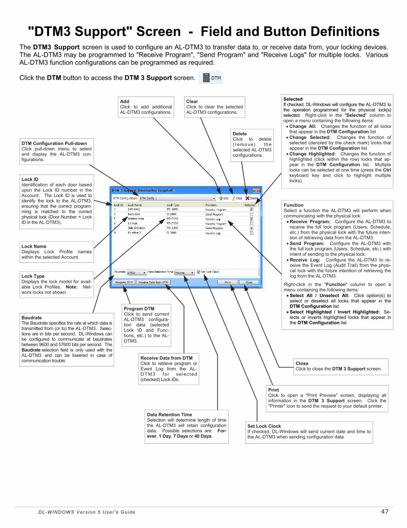
DL-WINDOWS Vers ion 5 User 's Guide 47
The DTM3 Support screen is used to configure an AL-DTM3 to transfer data to, or receive data from, your locking devices. The AL-DTM3 may be programmed to "Receive Program", "Send Program" and "Receive Logs" for multiple locks. Various AL-DTM3 function configurations can be programmed as required. Click the DTM button to access the DTM 3 Support screen.
"DTM3 Support" Screen - Field and Button Definitions
DTM Configuration Pull-down Click pull-down menu to select and display the AL-DTM3 con-figurations.
Add Click to add additional AL-DTM3 configurations.
Clear Click to clear the selected AL-DTM3 configurations.
Selected If checked, DL-Windows will configure the AL-DTM3 to the operation programmed for the physical lock(s) selected. Right-click in the "Selected" column to open a menu containing the following items:
• Change All: Changes the function of all locks that appear in the DTM Configuration list
• Change Selected: Changes the function of selected (denoted by the check mark) locks that appear in the DTM Configuration list
• Change Highlighted: Changes the function of highlighted (click within the row) locks that ap-pear in the DTM Configuration list. Multiple locks can be selected at one time (press the Ctrl keyboard key and click to highlight multiple locks)
Delete Click to delete ( remove) the selected AL-DTM3 configurations.
Function Select a function the AL-DTM3 will perform when communicating with the physical lock:
• Receive Program: Configure the AL-DTM3 to receive the full lock program (Users, Schedule, etc.) from the physical lock with the future inten-tion of retrieving data from the AL-DTM3.
• Send Program: Configure the AL-DTM3 with the full lock program (Users, Schedule, etc.) with intent of sending to the physical lock.
• Receive Log: Configure the AL-DTM3 to re-ceive the Event Log (Audit Trail) from the physi-cal lock with the future intention of retrieving the log from the AL-DTM3.
Right-click in the "Function" column to open a menu containing the following items:
• Select All / Unselect All: Click option(s) to select or deselect all locks that appear in the DTM Configuration list
• Select Highlighted / Invert Highlighted: Se-lects or inverts highlighted locks that appear in the DTM Configuration list
Close Click to close the DTM 3 Support screen.
Print Click to open a "Print Preview" screen, displaying all information in the DTM 3 Support screen. Click the "Printer" icon to send the request to your default printer.
Data Retention Time Selection will determine length of time the AL-DTM3 will retain configuration data. Possible selections are: For-ever, 1 Day, 7 Days or 40 Days.
Receive Data from DTM Click to retrieve program or Event Log from the AL-DTM3 for selected (checked) Lock IDs.
Program DTM Click to send current AL-DTM3 configura-tion data (selected Lock ID and Func-tions, etc.) to the AL-DTM3.
Baudrate The Baudrate specifies the rate at which data is transmitted from (or to) the AL-DTM3. Selec-tions are in bits per second. DL-Windows can be configured to communicate at baudrates between 9600 and 57600 bits per second. The Baudrate selection field is only used with the AL-DTM3 and can be lowered in case of communication trouble.
Lock Name Displays Lock Profile names within the selected Account.
Lock ID Identification of each door based upon the Lock ID number in the Account. The Lock ID is used to identify the lock to the AL-DTM3, ensuring that the correct program-ming is matched to the correct physical lock (Door Number = Lock ID in the AL-DTM3).
Lock Type Displays the lock model for avail-able Lock Profiles. Note: Net-worx locks not shown.
Set Lock Clock If checked, DL-Windows will send current date and time to the AL-DTM3 when sending configuration data.

48 DL-WINDOWS Vers ion 5 User 's Guide
Overview The hand-held AL-DTM3 Data Transfer Module acts as an intermediary between DL-Windows and the physical locking device(s). The AL-DTM3 allows for the transfer of lock data (Users, Schedules, etc.) from DL-Windows to your locking device, or in reverse (from your locking device to DL-Windows). An AL-PCI cable is required when transferring from DL-Windows to the AL-DTM3; a Double-ended Mini Banana Plug Connector (see page 4) is required for transferring data from the AL-DTM3 to the locking device(s).
When communications take place between DL-Windows and the lock(s), the Lock IDs must match in order for the data transfer to take place. If they do not match, communications will halt! DL-Windows assigns Lock IDs to the locks, and can be performed in two ways:
• Direct communication with your locking device using "Send All" or "Send Features"
• Communication with the AL-DTM3 using "Send Program to Lock" and Door Select Mode
Note: Door Select Mode (see below) should only be used when it is necessary to assign a Lock ID (usually first time programming of lock only). Thereafter, all AL-DTM3 communications should be performed in the "Lock Mode" of the AL-DTM3, ensuring the data is transferring correctly between DL-Windows and the lock(s) (see below for more information). Note: The AL-DTM3 displays the word "Door" and not "Lock ID" when referring to door numbers; in the AL-DTM3, both words are equivalent.
IMPORTANT: Be sure to make note of the EXISTING User 299 User Code (PIN). You will need this code later when transferring data from the AL-DTM3 to the lock(s). (See "Tip" below for a definition of the User 299 Code). AL-DTM3 Setup -- Operation Mode Note: If incorrect mode was selected, restart the AL-DTM3 by holding down both left and right buttons simultaneously for 5 seconds, then reselect the desired mode. Upon power up of the AL-DTM3, when prompted with "Operation Mode?", two choices are available: SELECT and STD:
SELECT – Chose SELECT Mode for first time data communications (by pressing left button). Then, choose between three modes: PC Comm Mode, Lock Mode, and Door Select Mode:
Communicating with the AL-DTM3 • PC Comm Mode is used to transfer programming
between DL-Windows and the AL-DTM3 • Lock Mode is used to transfer data between the AL-
DTM3 and the physical locks. The AL-DTM3 will automatically identify the Lock ID to which it is communicating
• Door Select Mode is used to transfer programming and to assign Lock ID numbers from DL-Windows (see step 6 below)
STD ("standard") – STD Mode will automatically put the AL-
DTM3 in PC Comm Mode when communicating with DL-Windows and will put the AL-DTM3 in Lock Mode when performing communications with the physical locks. STD Mode should be used for all subsequent communication after the Lock ID has been assigned.
Send Program to Lock When sending the DL-Windows programming to the
physical lock for the fist time, the AL-DTM3s "Operation Mode" should be in Select Mode. See previous section for more information. Note: For subsequent AL-DTM3 communications, use STD Mode and disregard step 6.
1. Plug the AL-PCI cable into the correct COM port in your PC and plug the other end (the two-pin banana plug connector) into the AL-DTM3, observing polarity (tab marked GND to black). It is expected that you have previously configured your AL-PCI cable. For more information about the AL-PCI setup and test, see page 43. Upon successful loopback test, proceed to next step.
2. Open the desired Account in DL-Windows containing the Lock Profiles with which you intend to communicate using the AL-DTM3. Note: For each physical lock with which you intend to communicate using the AL-DTM3, there must also be a corresponding Lock Profile in DL-Windows.
3. On the DL-Windows toolbar, click the DTM button and the DTM3 Support screen opens. All locks to which you can communicate using the AL-DTM3 will be listed in this screen.
4. For each lock you wish to send the program, double-click in Function area and in the pull-down select Send Program. In addition, click to add a check to the checkbox in the Selected column for each lock.
Note: Right-click function options may be used to set AL-DTM3 functions quickly (see the "Selected" column description detailed on page 47 for more information).
5. With the AL-DTM3 in PC COMM MODE, select
Program DTM and the following message will display:
User 299: "DTM Download" Code Entering the User Code (or proximity card)
assigned to User 299 allows that particular User to initiate communications between the AL-DTM3 and DL-Windows. NOTE: The User Code for User 299 is not an Access Code and is not used with the DL2800/DL3000 locks or the Networx™ wireless locks or devices.
TIP
Check the checkbox for Set Lock Clock (checked by default). If you do NOT want to send
the date and time to the AL-DTM3 and the physical lock, uncheck this checkbox and proceed to the next step.
TIP

DL-WINDOWS Vers ion 5 User 's Guide 49
Real-time packet communication will display in the DL-
Windows AL-DTM3 screen, as shown: Following a successful data transfer to the AL-DTM3,
the AL-DTM3 will emit several beeps (beeps are dependent on configuration data) and display a "Comm. Complete." message followed by a display of current memory block status.
6. For first time data communications to a lock, the AL-
DTM3 must be in Door Select Mode. Therefore, upon successful communication from DL-Windows, select NO for Lock Mode and select YES for Door Select Mode.
The AL-DTM3, now programmed, is ready to transfer
the data to the selected locks. The following messages will scroll back and forth on the AL-DTM3.
Continue to the next section for transferring data from
the AL-DTM3 to your physical locks. Transferring Data from the AL-DTM3 to Locks For first time data communications to your physical lock,
continue with step 1; for subsequent communications, skip to step 3.
1. The AL-DTM3 screen displays "Set Door TO=0001". The number "0001" refers to the lock assigned Lock ID # 1 in DL-Windows. If this is the first lock to be programmed, press the green button (SET). (To choose a different lock, the left AL-DTM3 button will toggle back through the list of locks and the middle button will toggle forward).
2. The AL-DTM3 screen displays "Ready, Door=xxxx" (xxxx
= Lock ID). Press left button (GO) and the screen will then toggle between:
3. Connect the AL-DTM3 to the lock by connecting the
Double-ended Mini Banana Plug Connector (see page 4) into the AL-DTM3 and into the lock that is to be programmed (observing polarity (GND tab to black).
4. Enter the User 299 User Code (PIN) or proximity card at
the physical lock. The AL-DTM3 briefly displays the message "Analyzing Lock – Please Standby" and then displays the following:
Note: Older AL-DTM models may require the re-entering
of the User 299 Code to continue. In most cases, do not press any buttons and continue.
During communication, the AL-DTM3 will display real-time packet data transfer between the AL-DTM3 and the lock:
After programming is complete, the following will display: After the initial programming of the locks with the AL-DTM3, Door Select Mode is no longer required. AL-DTM3 should now be used in STD Mode (Lock Mode). All changes can be communicated to and from the locks in this mode. DL2800 / DL3000 Only If the lock's Master Code and the DL-Windows Master
Code do not match, then the following AL-DTM3 screen will display:
Re-enter 299 Code to Continue
Door 0001, Send PGM Packet 001
Communicating with the AL-DTM3 (cont'd)
COMM. COMPLETE, 07/24/18 02:08PM
LOCK’S TIME AND DATE UPDATED.
0993 FREE MEMORY BLOCKS
(Current Date and Time)
(Current Memory Status)
MASTER CODE MISMATCH!
DOOR 03, SENDING PGM PACKET 000
0993 FREE MEMORY BLOCKS
COMM. COMPLETE, 07/24/18 12:08PM
Waiting for lock 04/25/18 02:30PM
DTM-III: Plug in then enter code
DOOR SELECT MODE YES NO
LOCK MODE YES NO
Waiting for lock 04/25/18 02:30PM
DTM-III: Plug in then enter code
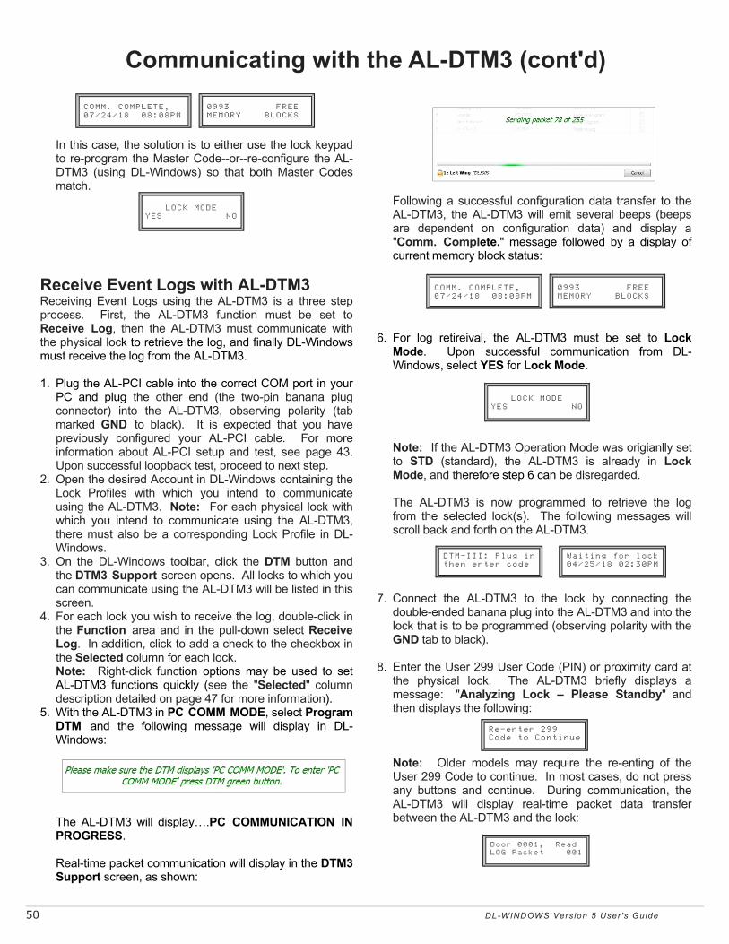
50 DL-WINDOWS Vers ion 5 User 's Guide
Following a successful configuration data transfer to the
AL-DTM3, the AL-DTM3 will emit several beeps (beeps are dependent on configuration data) and display a "Comm. Complete." message followed by a display of current memory block status:
6. For log retireival, the AL-DTM3 must be set to Lock
Mode. Upon successful communication from DL-Windows, select YES for Lock Mode.
Note: If the AL-DTM3 Operation Mode was origianlly set
to STD (standard), the AL-DTM3 is already in Lock Mode, and therefore step 6 can be disregarded.
The AL-DTM3 is now programmed to retrieve the log
from the selected lock(s). The following messages will scroll back and forth on the AL-DTM3.
7. Connect the AL-DTM3 to the lock by connecting the
double-ended banana plug into the AL-DTM3 and into the lock that is to be programmed (observing polarity with the GND tab to black).
8. Enter the User 299 User Code (PIN) or proximity card at
the physical lock. The AL-DTM3 briefly displays a message: "Analyzing Lock – Please Standby" and then displays the following:
Note: Older models may require the re-enting of the
User 299 Code to continue. In most cases, do not press any buttons and continue. During communication, the AL-DTM3 will display real-time packet data transfer between the AL-DTM3 and the lock:
In this case, the solution is to either use the lock keypad
to re-program the Master Code--or--re-configure the AL-DTM3 (using DL-Windows) so that both Master Codes match.
Receive Event Logs with AL-DTM3 Receiving Event Logs using the AL-DTM3 is a three step process. First, the AL-DTM3 function must be set to Receive Log, then the AL-DTM3 must communicate with the physical lock to retrieve the log, and finally DL-Windows must receive the log from the AL-DTM3. 1. Plug the AL-PCI cable into the correct COM port in your
PC and plug the other end (the two-pin banana plug connector) into the AL-DTM3, observing polarity (tab marked GND to black). It is expected that you have previously configured your AL-PCI cable. For more information about AL-PCI setup and test, see page 43. Upon successful loopback test, proceed to next step.
2. Open the desired Account in DL-Windows containing the Lock Profiles with which you intend to communicate using the AL-DTM3. Note: For each physical lock with which you intend to communicate using the AL-DTM3, there must also be a corresponding Lock Profile in DL-Windows.
3. On the DL-Windows toolbar, click the DTM button and the DTM3 Support screen opens. All locks to which you can communicate using the AL-DTM3 will be listed in this screen.
4. For each lock you wish to receive the log, double-click in the Function area and in the pull-down select Receive Log. In addition, click to add a check to the checkbox in the Selected column for each lock.
Note: Right-click function options may be used to set AL-DTM3 functions quickly (see the "Selected" column description detailed on page 47 for more information).
5. With the AL-DTM3 in PC COMM MODE, select Program DTM and the following message will display in DL-Windows:
The AL-DTM3 will display….PC COMMUNICATION IN
PROGRESS. Real-time packet communication will display in the DTM3
Support screen, as shown:
Communicating with the AL-DTM3 (cont'd)
0993 FREE MEMORY BLOCKS
COMM. COMPLETE, 07/24/18 08:08PM
LOCK MODE YES NO
Waiting for lock 04/25/18 02:30PM
DTM-III: Plug in then enter code
Re-enter 299 Code to Continue
Door 0001, Read LOG Packet 001
0993 FREE MEMORY BLOCKS
COMM. COMPLETE, 07/24/18 08:08PM
LOCK MODE YES NO
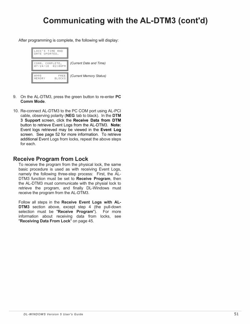
DL-WINDOWS Vers ion 5 User 's Guide 51
After programming is complete, the following will display: 9. On the AL-DTM3, press the green button to re-enter PC
Comm Mode. 10. Re-connect AL-DTM3 to the PC COM port using AL-PCI
cable, observing polarity (NEG tab to black). In the DTM 3 Support screen, click the Receive Data from DTM button to retrieve Event Logs from the AL-DTM3. Note: Event logs retrieved may be viewed in the Event Log screen. See page 52 for more information. To retrieve additional Event Logs from locks, repeat the above steps for each.
Receive Program from Lock To receive the program from the physical lock, the same
basic procedure is used as with receiving Event Logs, namely the following three-step process: First, the AL-DTM3 function must be set to Receive Program, then the AL-DTM3 must communicate with the physial lock to retrieve the program, and finally DL-Windows must receive the program from the AL-DTM3.
Follow all steps in the Receive Event Logs with AL-
DTM3 section above, except step 4 (the pull-down selection must be "Receive Program"). For more information about receiving data from locks, see "Receiving Data From Lock" on page 45.
Communicating with the AL-DTM3 (cont'd)
COMM. COMPLETE, 07/24/18 02:08PM
LOCK’S TIME AND DATE UPDATED.
0993 FREE MEMORY BLOCKS
(Current Date and Time)
(Current Memory Status)

52 DL-WINDOWS Vers ion 5 User 's Guide
"Event Log" Screen - Field and Button Definitions
In the Event Log screen, each column heading (Date, Time, etc.) can be clicked to
sort its data.
TIP
The Event Log screen is used to view each Event (also called the "Audit Trail") retrieved from your physical lock(s). Event Logs are obtained using various methods including direct communication, AL-DTM3 transfer as well as wirelessly (with Networx locks). Event Logs display a record of activity of various lock functions and User access. Each Log entry is denoted by its date/time and when applicable, its User Number to identify the credential. Click the Log button to access the Event Log screen.
User No. The number corresponding to each User within the lock (1-5000). See the Terminology entry on page 7.
Date The date the event occurred (MM/DD/YY).
Time The time the event occurred (hh:mm:ss AM/PM).
Name The name corresponding to each User within the lock. Most often, this is the name corre-sponding to each User within the lock. Group and Schedule data may also be displayed.
Event Description of each logged event (lock action, keypad function, Schedule, etc.) that occurred at the physical lock.
Max. Event Log Length From the pull-down, select the maximum Event Log length to be displayed (50 - 40,000). Note: Selection also deter-mines the number of Event Logs to be retrieved.
Default View Click to revert Event Log back to original format after sorting.
Export Log Click the Export Log button and two selections appear (as shown below): You can click either Export Log to Text File or Export Log to CSV File.
• If you click Export Log to Text File, the log will be saved in the form of a .txt (text) file, and a popup will appear detailing the name and path of the file.
• If you click Export Log to CSV File, the log will be saved in the form of a CSV (Comma Separated Value or comma delimited) file, and a dialog will appear allowing you to save the file to a desired location. Note: This CSV file can be viewed in MS Excel, and each column in the list will be aligned in Excel under its own column heading.
Clear Log Click to permanently clear all existing Event Log data from the Event Log screen (not the physical lock) until next retrieval.
Print Click to open a "Print Pre-view" screen, displaying ALL information in the Event Log screen (the total number of Event Log records). Click the "Printer" icon to send the request to your default printer.
Close Click to close the Event Log screen.

DL-WINDOWS Vers ion 5 User 's Guide 53
The Options screen allows for the selection of "Account" and "DL-Windows database" preferences. For example, the Options screen is where you can set the Ambush Code (same for all Lock Profiles within an Account), the Custom field (same for all Accounts within the DL-Windows database). Note: Account-wide Options are denoted by "ACC"; DL-Windows database-wide options are denoted by "DB"). Click the Options button to access the Options screen.
"Options" Screen - Field and Button Definitions
Send Schedule from Schedule View (DB) When keypad programmed Schedules are up-loaded (received) into DL-Windows, Schedules can only be viewed in the Schedule View screen, NOT the Schedule screen. Therefore, in this situation, when sending data back to the physical lock, this option must be checked so that Schedule data may be re-used. IMPORTANT: If this option is checked, when creating Schedules in the Schedule screen, if "Switch to Schedule View" is not selected (Schedule View screen empty) upon download, no Schedule data will be sent to the lock.
Use Ambush Code in Global Users (ACC) If checked, pull-down will allow the selection of a two-digit Code that will activate the relay when this Code entered before a valid credential. Note: Must be used with "Ambush Function Activated" Feature (located in the Features screen, Relay tab). If the Ambush Code conflicts with an existing PIN, field must be changed or disabled before exiting the Options screen.
Global Users Custom Field Label Name (DB) This customizable field controls the label name of the Custom field located under the PIN field in the Global Users screen. For example, you can use the Social Security number as the name of the new field, for all Users in DL-Windows.
Startup Screens (DB) Check to enable select screens to open automatically when any Lock Profile is opened.
Close Click to close the Options screen.
Sequential Max Card Customizable field that determines the maximum number of cards allowed to be sequentially added from the Card Enrolling screen. See page 20 for more information ("Sequential Add"). Maximum is 10000.
Show Global Reference Numbers (ACC) If checked, the Global Reference Number is displayed in the Global Users screen. Note: Global Reference Numbers are not related to User Numbers nor to Programming Levels. The number acts as an internal designation only. See Terminology on page 7 for more information.
Open Event Log Viewer on Receive (DB) Check to allow the Event Log screen to open automatically after receiving data from a lock.
Working Directory (DB) Select the directory in which newly created DL-Windows files will reside.
Language Support (DB) From the pull-down list select the language that will popu-late all DL-Windows screens.
Enable User 300 on download (ACC) If checked, User 300 (the "one time" service User Code normally enabled by User 297) will be enabled upon every "User" download from DL-Windows to your lock. See User 297: Quick Enable User 300 on page 7.

54 DL-WINDOWS Vers ion 5 User 's Guide
Tools Menu (Expanded) The following Tools menu items can impact the security of your DL-Windows installation, and are therefore limited to DL-Windows Administrators only. Set Security Password In MOST cases, the Security Password is only used with Networx installations, however it can also be used to increase security in the non-Networx (AL-DTM3 and direct communication) installations. The Security Password ensures that only your copy of DL-Windows can communicate with your locks or your AL-DTM3. Once set, an internal link is created between DL-Windows, the AL-DTM3 (if applicable) and your physical locks. Therefore, other copies of DL-Windows will be unable to communicate with your locks unless your Security Password is set in those copies of DL-Windows prior to the attempted communication. IMPORTANT: The Security Password cannot be changed and cannot be retrieved. If you wish to change or remove the Security Password, the Account may be cloned to remove the Security Password in the new Account (see page 16 for more information about cloning Accounts). To change or remove the Security Password in the locks and/or the AL-DTM3, each lock (or AL-DTM3) must be manually defaulted and re-downloaded with the new (or blank) Security Password.
To set the Security Password, click Tools > Set Security Password. In the dialog that appears, type a unique 6 character (no more, no less) password in the New Password field. Retype the password in the Confirm field and click OK to set the Security Password, or click Cancel to exit without saving changes. Backup / Restore Database All contents of the DL-Windows database may be backed up and restored at any time. It is important to ensure the safety of the database so that it may be restored at any time or restored to another copy of DL-Windows, if necessary. To Backup: Click Tools > Backup Database to open the
Save As dialog, pointing to a default Backup folder located in your Microsoft SQL Server folder. Note: Backup files may be save to any desired location, including a thumb (USB) drive, etc. To Restore: Click Tools > Restore Database. In the dialog that appears, select the location of the database file (by default, an "AlarmLock.5.x.x.bak" file) and click Open. Note: When restoring a database, the DL-Windows software version must be identical to the version that was used to backup the database. Export / Import Accounts Any Account in your DL-Windows database may be exported or imported at any time. This will allow individual Accounts to be transferred between different installations of DL-Windows. To Export Click Tools > Export Account to open the Save As dialog. Files may be exported to any desired location, including a thumb (USB) drive, etc. To Import Click Tools > Import Account. In the dialog that appears, select the location of the .acc file and click Open. The Import Account dialog appears. Type a description of the Account and click OK. Note: When importing an Account, the DL-Windows so f tware version must be identical to the version that was used to export the Account.

DL-WINDOWS Vers ion 5 User 's Guide 55
Tools Menu (Expanded) (cont'd)
Export / Import Global Users To / From .CSV This feature allows a Global User database to be created in Microsoft Excel and imported into DL-Windows. Conversely, one can also export your entire Global User database to a single .csv file for use in Microsoft Excel. Export to .CSV Open desired Account and Lock Profile. Then click Tools > Export Global Users to .CSV. The Save As dialog appears; select desired location and click Save. When viewing the exported Account file in Excel, note the cell configuration shown below:
Cell A1 = First Name Cell B1 =Last name Cell C1 = PIN Cell D1= Address Cell E1= City Cell F1= State Cell G1 = Zip Code Cell H1 = Telephone Cell I1 = Custom Field
Import from .CSV Create a spreadsheet following the cell configuration detailed above for the Global User data. Note: Any cell not used should be left blank. Invalid characters will be ignored and not imported (for example, letters in the Telephone field). Upon completion, the MS Excel file must be saved as a comma delimited file by clicking File > Save As…, then in the Save as type: pull-down, select CSV (Comma delimited) (*.csv).
An example of one line of an MS Excel spreadsheet: The above MS Excel file will populate in DL-Windows as shown: Cell Guidelines Be sure to follow the following guidelines when entering cell data in MS Excel:
• No letters or invalid characters (question mark, slash, dashes, etc.) in the PIN, Zip Code or Telephone fields
• Maximum 6 digits in PIN field • Maximum 6 digits in the Zip Code field • Maximum two letters in State field
Note: When importing Users, it is important to verify there are sufficient empty Slots in the Global Users screen User List for the Users attempting to be imported (default = 100 slots). To add more slots, right click the User List and select "Add a Block of Empty Slots to list", then type the desired quantity.

56 DL-WINDOWS Vers ion 5 User 's Guide
As shown above, the default setting of "ON" should be
retained if Lock ID numbers have not yet been programmed and you wish to use the AL-DTM3 to assign Lock ID numbers to existing locks, or if Lock ID numbers are to be changed. Otherwise set Door Select Mode to "OFF". Press the green button to select and exit this option.
6. Additional configuration and diagnostic options display in
turn on each press of the green button; when SLEEP THEN POWER DOWN appears, press and hold the green button to exit Configuration Mode. Note: UNCONDITIONAL FLASH ERASE erases all lock information and configured settings in the AL-DTM3. To reset the AL-DTM3 to its factory default settings, remove the battery, press and hold the green button for 10 seconds, then replace the battery.
7. The unit may now be powered up with the new feature(s)
enabled. AL-DTM3 Specifications
Power Requirements:..........(One) 9V Alkaline battery, Duracell MN1604 or equivalent
Battery Life Standby Mode:..................60 Hours Sleep Mode: ......................1 Year
Operating Temperature:......0 - 49ºC (32-122ºF) Dimensions (H x W x D): .....19 x 10 x 3.8cm (7.5 x 4 x 1.5")
The AL-DTM3 may be configured for Foreign Language support and the Door Select feature (see below). Warning: Entering the following Configuration Mode will clear all data (lock information) from memory.
1. Place AL-DTM3 into PC Comm Mode. If not already in PC Comm Mode, press green button to enter this mode.
2. Press and HOLD both the left and green buttons on the
AL-DTM3. After several messages appear, release the buttons when the display reads:
When the display reads "CONFIG. LANGUAGE", the AL-
DTM3 has entered Configuration Mode. Note: Pressing the green button allows you to step
through each configuration option in turn; after the last option, the list repeats ("CONFIG. LANGUAGE" re-appears).
3. If you wish to configure the first option, Language, press
and hold the green button (otherwise press and release the green button to skip to the next option shown in step 4).
Set the language (as shown above) with the left and
middle black buttons, then press the green button to select the language AND exit this option.
4. The next option appears: CONFIG. FOR DTM-III MODE.
For DL-Windows 3.5x and above, this mode MUST be set to "ON". Therefore, enter this option by pressing and holding the green button. The following screen appears:
As shown above, the default setting is "ON". Press the
green button to both select DTM-III mode and exit this option.
5. The next option appears: CONFIG. DOOR SELECT MODE.
Enter this option by pressing and holding the green button. The following screen appears:
LANGUAGE = ENGLISH <BACK NEXT> EXIT
DOOR SELECT = ON ON OFF EXIT
CONFIG. LANGUAGE
AL-DTM3 Specifications and Configuration
CLOCK TEST.
LCD DIS. TEST.
LOW BAT. TEST.
FLASH MEM. TEST.
EXIT TO STANDBY
UNCONDITIONAL FLASH ERASE
SLEEP THEN POWER DOWN
Hold Down to Shutdown AL-DTM3
DTM-III MODE= ON ON OFF EXIT
PC COMM MODE . . . .
Entering Config/Test Mode
(Release buttons when displayed)

DL-WINDOWS Vers ion 5 User 's Guide 57
ACCESS = Entry into a restricted area. AMBUSH = A special Code entered at the keypad when the
User is forced to unlock a device. The device unlocks but sends a silent alarm with no indication at the keypad. Can be used to trip a relay, to alert security, or trip a silent alarm on a Burglary Control Panel.
AUDIT TRAIL = A date/time stamped log of previous lock
events. BURGLARY CONTROL PANEL = Provides local alarm and
remote communication to request security for burglary/break-in. A relay output used for Ambush can provide a silent alarm and call-for-help.
CLOCK
• REAL TIME CLOCK = An accurate built-in clock that allows date/time stamping of events. The clock can be slowed or speeded up to fine tune long term accuracy to within three minutes per year.
• CLOCK SETTINGS = Printout includes date, time, weekday, and clock speed.
• CLOCK SPEED = The clock can be adjusted to allow faster/slower speeds and therefore increasing clock accuracy.
CODE = Numeric sequence of numbers (such as: 1234) entered at the keypad. If Star-Enter-Key is required, must be followed by a [:] key.
• AMBUSH CODE = See Ambush. • BASIC USER CODE = User Codes assigned to User
Numbers 12+ (except Users 297-300). (Does not allow programming)
• INSTALLER CODE = User Codes assigned to User Numbers 2 and 3. (Allows all programming except Master functions).
• INVALID CODE = A User Code that has not been programmed in the lock.
• MANAGER CODE = User Codes assigned to User Numbers 4 through 6. (Allows most of the programming functions).
• MASTER CODE = User Code assigned to User Number 1. Default (factory) Master Code is 123456. The User with the Master Code has complete control of the lock.
• PRINT ONLY USER CODE = User Code assigned to Users 10 and 11. (Allows no programming except print functions).
• QUICK ENABLE USER 300 CODE = Refers to the User Code entered by User 297 which (when entered at the keypad) enables the User Code assigned to User 300 for one time only.
• QUICK PC ACCESS CODE = Permits upload/download to DL-Windows Software on IBM/compatible computer running Microsoft Windows 95, 98, or NT 4.0. Refers to the User Code for User 298.
• SERVICE CODE = User 300 User Code. Allows only
one entry, then needs to be re-enabled by the User 297 User Code to regain access.
• SUPERVISOR CODE = User Codes assigned to Users 7, 8 and 9. Can only program day-to-day operation.
• USER CODE = Code used by Users. Code is 3 to 6 numeric digits long, allowing controlled entry.
• VALID CODE = An entered User Code that has been programmed in the device.
COM PORT = A computer serial communications port used to
communicate with the Lock and/or Data Transfer Module. CREDENTIAL = A generic word used to indicate a PIN
number pressed into a lock keypad, or a proximity card or proximity keyfob.
DATA TRANSFER MODULE = A device that permits transfer
of program/data between a computer and the lock. DATE = Month, Day and Year entered as MMDDYY. DAY OF WEEK = Sunday through Saturday (where 1 =
Sunday and 7 = Saturday). DEFAULT = "Default" settings are the original settings that
were set at the factory; in other words, it is the lock's original factory condition when the lock was first taken out of its box. The default settings are permanently encoded within the lock's fixed memory, and when the lock is first started, or when power is removed and re-applied, the original factory default settings are re-loaded and take effect.
DELETE = User Codes (PINs) and proximity credentials can
exist (occupy a User Number) within the lock programming, but are removed when "deleted". can be rendered inoperative (thus the entry of a non-existent PIN does not allow access). Similarly, when used with DL-Windows Operators and Administrators, "delete" describes an Operator or Administrator who's Name, Full Name, Type and Password was removed from DL-Windows.
DISABLE = User Codes (PINs) and proximity credentials can
exist (occupy a User Number) within the lock programming, but can be rendered inoperative (PIN entry does not allow access). Similarly, when used with DL-Windows Operators and Administrators, "disable" describes an Operator or Administrator who's Name, Full Name, Type and Password exist within DL-Windows but is rendered inoperative. Contrast with "enable," which means active and operational.
DOOR AJAR = If access is granted with the lock, and the door
is held open beyond the pre-programmed amount of time, the lock will trip a ‘Door Ajar’ event. If programmed, the lock will provide audible annunciation and/or an auxiliary relay closure.
DOOR NUMBER = Identification of each door with a specific
Glossary

58 DL-WINDOWS Vers ion 5 User 's Guide
Glossary (cont'd) number (1-2000). (Used with the AL-DTM and AL-DTM2. For the AL-DTM3, see glossary entry "Lock ID").
DOWNLOAD = Send data to lock or AL-DTM3. EMERGENCY COMMANDS = For use only with the Trilogy
Networx™ wireless network, wireless commands can be sent to all wireless locking devices in an Account during a crisis or other urgent situation: "Emergency Lock Down", to lock all doors in the Account; "Emergency Passage", to unlock all doors in the Account; and "Emergency Return to Normal" (non-emergency) operation. See OI383 for more information regarding the wireless Networx™ system, its supported locks and features.
ENABLE = See Disable ERASE = See Delete EVENTS = Recorded lock activity. FUNCTION (also called Programming Functions) = are the
numbers used to program lock features (enabling/disabling Users, User Groups, Passage Mode, Schedules, etc.).
FUNCTION CARDS (Used with the PL3000 lock only) = Nine
standard proximity cards labeled one through nine, enrolled into the PL3000 lock. Each card can perform a specific function, such as initiating PC communications or enrolling proximity cards. See WI1280 for more information.
GROUP
• USER GROUP = Defining a User to specific Groups, allows User entry when the Group is allowed entry.
• GROUP 1 DISARMS BURGLAR CONTROL = A Group 1 USER CODE entry can disarm an alarm panel during a predefined schedule. Should the Group 1 enter the lock outside of the scheduled time, the alarm will not disarm. The alarm panel must be armed through other means (such as an Alarm Panel Keypad). The Burglary Alarm Panel must be programmed to disarm from an Armed State Only and the zone input must be programmed for input disarming.
• GROUP 1 ENABLES GROUP 4 USERS = A Group 1 USER CODE entry during a predefined schedule will allow access to Group 4 Users.
• GROUP 1 PUTS UNIT IN PASSAGE = A Group 1 USER CODE entry during a pre-defined schedule will unlock unit.
GUARD TOUR = A Guard Tour Code is used to log the
movement of a security guard as he or she makes rounds from one assigned guard tour station to the next. A Guard Tour Code is used to log the movement of a security guard as he or she makes rounds from one assigned guard tour station to the next. Entering the User 299 code provides precise verification and accountability of a guard's movements by logging the location with a time/date stamp in the Event Log (Audit Trail). See OI383 for more
information regarding the wireless Networx™ system and its supported features.
INSTALLER = See.... CODE, INSTALLER CODE. KEYPAD = 10-numeric keys, : and special ; key.
• KEYPAD LOCKOUT = Keypad is programmed to
lockout Users, for a specified period of time, when a specified number of invalid User Codes are entered.
• KEYPAD PROGRAMMING = Ability to program the lock through the keypad.
KEYPRESS = Pressing a button on the Lock’s Keypad. LEVEL ABILITY = Predefined User Types (such as Master,
Installer, Manager, Supervisor, and Print Only User) have specific abilities to program and/or control the lock.
LOCK = A generic word used to indicate one of the many
Alarm Lock locking devices available, including devices such as the DK series keypads that trigger other locking devices.
LOCK PROFILE = See Profile LOCK ID = Identification of each door with a specific number--
or in other words, a number representing an individual lock within an Account. No longer entered through AL-59. For use with the AL-DTM3 (for the AL-DTM or the AM-DTM2, see glossary entry "Door Number".
The new Lock ID format was developed to increase the number of locks allowed per Account (now up to 2000 locks). As a result of this increase, the ability to change the Door Number (now called Lock ID) at the lock keypad is no longer used. DL-Windows (versions 3.5.3 and greater) software must now be used to change the Lock ID. When DL-Windows version 3.5+ data is sent to the lock, this Lock ID is updated.
If you wish to receive data from the lock before data is sent, the new "Update Lock ID" option in DL-Windows version 3.5+ will change or update the Lock ID. In addition, the current keypad Function 59 (in Programming Mode) is no longer allowed, and is consequently ignored by the DL-Windows software.
LOCKOUT ATTEMPTS = A specified number of invalid User
Code entries (1-9), that will disable the keypad for a predefined period of time (1-60 seconds).
LOCKOUT TIME = A predefined time (1-60) seconds that the
lock will stop accepting User Codes, after a specified number of invalid User Code entries (1-9).
LOG = See... AUDIT TRAIL. MANAGER = See... CODE, MANAGER CODE.

DL-WINDOWS Vers ion 5 User 's Guide 59
Glossary (cont'd) MASTER = See... CODE, MASTER CODE. NETWORX = For information regarding the programming of
the wireless Trilogy Networx™ system, where programming features can be sent wirelessly using a computer network, see OI383.
PASSAGE = Allow anyone to pass through the door without
USER CODES (door is unlocked). PROFILE = A Lock Profile contains the instructions that a lock
uses to perform its various functions. Use DL-Windows to create a Lock Profile on your computer, and then transfer and store the Profile in the circuitry contained inside the lock itself. The Lock Profile is essentially a computer database file that maintains feature settings, schedules, audit trails, etc. Using DL Windows, Lock Profiles can be created with default information (see "default" Glossary entry), edited on your PC, and then sent to (and even received from) locks.
PROXIMITY CREDENTIAL = See Credential PRINTER = A printout device such as an infrared printer or
computer printer. PRIVACY MODE (Factory Default for 4100 Series Locks):
"Privacy Mode" is designed to allow access to individuals with access codes (or PROX cards) and is typically used for rooms needing privacy from others such as bathrooms, dorms and meeting rooms.
PROGRAM MODE = A mode allowing program/data to be
entered through the keypad. Only specific Users can program a lock manually, by entering their USER CODE, followed by the [;] key. To exit program mode, hold any key until repeated beeps are heard.
PROGRAMMABLE RELAY FUNCTIONS = The relay can be
programmed for one or more functions. PROXIMITY CARDS = HID ProxCards® and ProxKey® keyfobs are access control cards manufactured in a variety of bit formats.* RELAY = Switched output allowing remote control of other
devices. External power source is required. • Relay, Ambush Activated - Ambush Code entered prior
to a User Code will trip a relay. This can alert Security or trip a zone on an Alarm Panel.
• Relay, Any Keypress - First keypress of any sequence. • Relay, Authorized Entry - Valid User Code entered. • Relay, Disabled User Entered Code - Valid User Code
entered but the User is disabled. • Relay, Failed Entry Attempt - Invalid User Code
entered. • Relay, Keypad Lockout - Should several Invalid User
Codes be entered that exceed the number of lockout attempts (1-9), then the lock will stop accepting keypad entries for the Lockout Time (1-60 seconds). The Relay output can be used to indicate tampering of the keypad.
• Relay, Group 1 Activation - A Group 1 User can enter a User Code and can disarm a Burglary Alarm Panel using the Relay Output.
• Relay, On Door Ajar - Relay will activate when Door is found to be ajar, that is, left open after a specified period of time.
REMOTE INPUT = Entry into a restricted area, by pressing a
button connected to the REMOTE INPUT WIRES (White and White) by someone on the other side of the door.
RESIDENCY MODE (Factory Default for 4500 Series Locks):
The "Residency Feature" is provided to prevent a person from unintentionally having the door lock behind them when stepping outside briefly. Typically used in retirement homes and college dormitories.
SCHEDULE = A programmed operation (enable/disable, lock/
unlock, etc.) on a specific day (Sunday through Saturday) and time.
SCHEDULES, QUICK = Any one of four most common types
of schedules can be programmed. TIME = Hours and Minutes in the HHMM format. TIME/DATE STAMP = A recorded date and time that an event
occurred. TIMEOUT = Immediate operation for a specified number of
hours. TWO DOOR MODE = For use with the Networx™
NETWORXPANEL control panel. See OI383 for more information regarding the wireless Networx™ system and its supported features, including "Two Door Mode".
UPLOAD = Receive data from the lock or AL-DTM3. USER = A person who has been provided with a USER CODE
for access through the door. USER LOCKOUT, TOTAL = All Users (except for Master
Code) have been locked out.

60 DL-WINDOWS Vers ion 5 User 's Guide
ALARM LOCK SYSTEMS, INC. (ALARM LOCK) warrants its products to be free from manufacturing defects in mate-rials and workmanship for twenty four months following the date of manufacture. ALARM LOCK will, within said pe-riod, at its option, repair or replace any product failing to operate correctly without charge to the original purchaser or user.
This warranty shall not apply to any equipment, or any part thereof, which has been repaired by others, improperly installed, improperly used, abused, altered, damaged, sub-jected to acts of God, or on which any serial numbers have been altered, defaced or removed. Seller will not be re-sponsible for any dismantling or reinstallation charges, environmental wear and tear, normal maintenance ex-penses, or shipping and freight expenses required to re-turn products to ALARM LOCK. Additionally, this warranty shall not cover scratches, abrasions or deterioration due to the use of paints, solvents or other chemicals.
THERE ARE NO WARRANTIES, EXPRESS OR IM-PLIED, WHICH EXTEND BEYOND THE DESCRIPTION ON THE FACE HEREOF. THERE IS NO EXPRESS OR IMPLIED WARRANTY OF MERCHANTABILITY OR A WARRANTY OF FITNESS FOR A PARTICULAR PUR-POSE. ADDITIONALLY, THIS WARRANTY IS IN LIEU OF ALL OTHER OBLIGATIONS OR LIABILITIES ON THE PART OF ALARM LOCK.
Any action for breach of warranty, including but not limited to any implied warranty of merchantability, must be brought within the six months following the end of the war-ranty period.
IN NO CASE SHALL ALARM LOCK BE LIABLE TO ANY-ONE FOR ANY CONSEQUENTIAL OR INCIDENTAL DAMAGES FOR BREACH OF THIS OR ANY OTHER WARRANTY, EXPRESS OR IMPLIED, EVEN IF THE LOSS OR DAMAGE IS CAUSED BY THE SELLER'S OWN NEGLIGENCE OR FAULT.
In case of defect, contact the security professional who installed and maintains your security system. In order to exercise the warranty, the product must be returned by the security professional, shipping costs prepaid and insured to ALARM LOCK. After repair or replacement, ALARM LOCK assumes the cost of returning products under war-ranty. ALARM LOCK shall have no obligation under this warranty, or otherwise, if the product has been repaired by others, improperly installed, improperly used, abused, al-tered, damaged, subjected to accident, nuisance, flood, fire or acts of God, or on which any serial numbers have been altered, defaced or removed. ALARM LOCK will not be responsible for any dismantling, reassembly or reinstal-lation charges, environmental wear and tear, normal main-tenance expenses, or shipping and freight expenses re-quired to return products to ALARM LOCK. Additionally, this warranty shall not cover scratches, abrasions or dete-rioration due to the use of paints, solvents or other chemi-cals.
This warranty contains the entire warranty. It is the sole warranty and any prior agreements or representations, whether oral or written, are either merged herein or are expressly cancelled. ALARM LOCK neither assumes, nor authorizes any other person purporting to act on its behalf to modify, to change, or to assume for it, any other war-ranty or liability concerning its products.
In no event shall ALARM LOCK be liable for an amount in excess of ALARM LOCK's original selling price of the product, for any loss or damage, whether direct, indirect, incidental, consequential, or otherwise arising out of any failure of the product. Seller's warranty, as hereinabove set forth, shall not be enlarged, diminished or affected by and no obligation or liability shall arise or grow out of Seller's rendering of technical advice or service in connection with Buyer's order of the goods furnished hereunder.
ALARM LOCK RECOMMENDS THAT THE ENTIRE SYS-TEM BE COMPLETELY TESTED WEEKLY.
Warning: Despite frequent testing, and due to, but not limited to, any or all of the following; criminal tampering, electrical or communications disruption, it is possible for the system to fail to perform as expected. ALARM LOCK does not represent that the product/system may not be compromised or circumvented; or that the product or sys-tem will prevent any personal injury or property loss by burglary, robbery, fire or otherwise; nor that the product or system will in all cases provide adequate warning or pro-tection. A properly installed and maintained alarm may only reduce risk of burglary, robbery, fire or otherwise but it is not insurance or a guarantee that these events will not occur. CONSEQUENTLY, SELLER SHALL HAVE NO LI-ABILITY FOR ANY PERSONAL INJURY, PROPERTY DAMAGE, OR OTHER LOSS BASED ON A CLAIM THE PRODUCT FAILED TO GIVE WARNING. Therefore, the installer should in turn advise the consumer to take any and all precautions for his or her safety including, but not limited to, fleeing the premises and calling police or fire department, in order to mitigate the possibilities of harm and/or damage.
ALARM LOCK is not an insurer of either the property or safety of the user's family or employees, and limits its li-ability for any loss or damage including incidental or con-sequential damages to ALARM LOCK's original selling price of the product regardless of the cause of such loss or damage.
Some states do not allow limitations on how long an im-plied warranty lasts or do not allow the exclusion or limita-tion of incidental or consequential damages, or differenti-ate in their treatment of limitations of liability for ordinary or gross negligence, so the above limitations or exclusions may not apply to you. This Warranty gives you specific legal rights and you may also have other rights which vary from state to state.
ALARM LOCK LIMITED WARRANTY