door interlock systems installation & operation manual user manual.pdf · 1 | p a g e door...
TRANSCRIPT

1 | P a g e
Door Interlock Systems Installation & Operation Manual
(DIS-4X; DIS-4SV; DIS-2X)
Door Interlock Systems revised Ver. 1.01 on date 16 Feb 2012
Due to continuous technology up-gradation, product specifications and features are subject to change without notice at an y time.
It is Smart I’s goal to supply accurate and reliabl e documentation. If you
discover a discrepancy in this document or Need Hel p, please e-mail your comments to
Smart-I Electronics Systems Pvt. Ltd . 119, Neha Industrial Estate,
Opp. Tata Steel, Dattapada Road, Borivali (East) Mumbai – 400 066.
Tel: + 91-22-40744444 / Telefax: +91-22-40744455 Email- [email protected]
2 | P a g e
TABLE OF CONTENT
WARNING & CAUTION _________________________________ ___________3
INTRODUCTION:- _________________________________________________4
PRODUCT FEATURE ______________________________________________4
PRODUCT SPECIFICATION:- _______________________________________5
BLOCK DIAGRAM FOR 2 DOORS DIS:- ___________________ ___________6
GENERAL ARRANGEMENT DIAGRAM OF SYSTEM FOR 4DIS SYST EM:- __8
MASTER 2-DIS BOARD CONNECTION DETAILS: ____________ __________9
MASTER 4-DIS MASTER BOARD CONNECTION DETAILS:- ____ ________10
SLAVE 4-DIS SLAVE BOARD CONNECTION DETAILS:- ______ __________11
4 DIS PCB CONNECTOR DETAILS:- _____________________ ___________12
4 DIS PCB LED DETAILS:- ___________________________ _____________15
DOOR CONNECTIONS FOR EML AND STRIKE LOCK:- ________ ________15
DOOR CONNECTIONS FORMAGNETIC CONTAC:- _____________ ______15
FACIA PLATE CONNECTION DETAILS:- __________________ ___________16
SYSTEM OPERATION:- ___________________________________________17
PROGRAM DOORS LOGICALLY USING KEYPAD:- ____________ ________18
KEYPAD FUNCTION DETAILS FOR 4 DIS SYSTEM:- ________ ___________18
DIS INTEGRATION WITH ACCESS CONTROLLER SYSTEM _____ _______20

3 | P a g e
WARNING & CAUTION Ø Do not opens system or places it near other heavy electrical equipments. The system is
sensitive to Electro Static Discharge (ESD) Ø Do not power on the system without reading this ma nual. Ensure proper power supply
with Earthing. Ø Note down the serial number and model no. of the d evice for future reference and quote
in all support and service requests. Ø Mounting the unit in strong sunlight may affect us er visibility of the LCD. Ensure that
the LCD and LED’s are clearly visible in all lighti ng conditions. Ø Do not use this unit near water. Ø Never insert objects of any kind into the unit or through the cabinet slots as they may
touch voltage points and/or short circuit parts pos sibly resulting in fire or electric shock. Never spill liquid of any kind on the unit.
Ø Power up the controller only when installation is complete.
Important instructions:
1. Care should be taken identifying the wires. Impr oper wiring may render permanent damage to the device or personal injury.
2. Check the earthing at the site before installing the controllers. Normally the earthing should be between 1V to 2V only. Earthing on the higher side may damage the controller or its various other componen ts.
3. Max allowable cable distance between Master DIS & Slave DIS is up to 1.5 mtr to 2 mtr
4 | P a g e
Introduction:- DIS is designed and manufactured state-of-the-art door interlock/access systems for clean rooms, containment suites, laboratories - in fact any critical area that requires door access control with additional security. It is an USER PROGRAMMABLE Door Interlock System, This system is designed to suit modern door interlocking requirements. DIS has Master-Slave Configuration and can be configured up to maximum 8 doors in loop.
The unit is flexible and can be configured on site by the user for required door locking logic
Product Feature
1. Programmable Micro controller based Door Interlock unit 2. One “4 - DIS Master” system can control up to 4 Doors 3. By adding “4-DIS Slave” system can control up to 8 Doors 4. Master & slave configuration. (Max. salves 1 no.)
Each Master & slave control 4 Doors in DIS (i.e. totally 8 Doors) 5. One Emergency / Fire input is used to open all doors automatically on following
events • Fire input activated by alarm output of fire panel, connected to only at Master
unit • Emergency input activated by user, using Emergency button connected to
only Master unit 6. Different modes of operation
• Inter-lock logic standard / programmed selected by Pro-keypad on Master 7. Status of individual door is also indicated on Door Facia Plate.
• “OPEN” --------- Door Opened • “LOCK” --------- Door is Lock
5 | P a g e
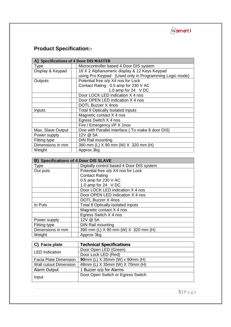
Product Specification:- A) Specifications of 4 Door DIS MASTER
Type Microcontroller based 4 Door DIS system Display & Keypad 16 X 2 Alphanumeric display & 12 Keys Keypad
using Pro Keypad (Used only in Programming Logic mode) Outputs Potential free o/p X4 nos for Lock
Contact Rating : 0.5 amp for 230 V AC 1.0 amp for 24 V DC
Door LOCK LED indication X 4 nos Door OPEN LED indication X 4 nos DOTL Buzzer X 4nos Inputs Total 9 Optically Isolated inputs Magnetic contact X 4 nos Egress Switch X 4 nos Fire / Emergency I/P X 1nos Max. Slave Output One with Parallel Interface ( To make 8 door DIS) Power supply 12V @ 5A Fitting type DIN Rail mounting Dimensions in mm 390 mm (L) X 90 mm (W) X 320 mm (H) Weight Approx 3kg B) Specifications of 4 Door DIS SLAVE Type Digitally control based 4 Door DIS system Out puts Potential free o/p X4 nos for Lock
Contact Rating 0.5 amp for 230 V AC 1.0 amp for 24 V DC
Door LOCK LED indication X 4 nos Door OPEN LED indication X 4 nos DOTL Buzzer X 4nos In Puts Total 8 Optically Isolated inputs Magnetic contact X 4 nos Egress Switch X 4 nos Power supply 12V @ 5A Fitting type DIN Rail mounting Dimensions in mm 390 mm (L) X 90 mm (W) X 320 mm (H) Weight Approx 3kg C) Facia plate Technical Specifications
LED Indication Door Open LED (Green) Door Lock LED (Red)
Facia Plate Dimension 90mm (L) X 35mm (W) x 90mm (H) Wall cutout Dimension 48mm (L) X 35mm (W) X 70mm (H) Alarm Output 1 Buzzer o/p for Alarms
Input Door Open Switch or Egress Switch
6 | P a g e
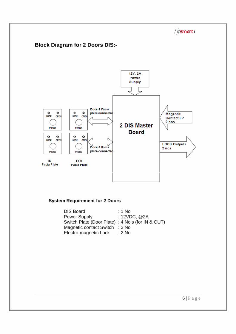
Block Diagram for 2 Doors DIS:-
System Requirement for 2 Doors
DIS Board : 1 No Power Supply : 12VDC, @2A Switch Plate (Door Plate) : 4 No’s (for IN & OUT) Magnetic contact Switch : 2 No Electro-magnetic Lock : 2 No
7 | P a g e
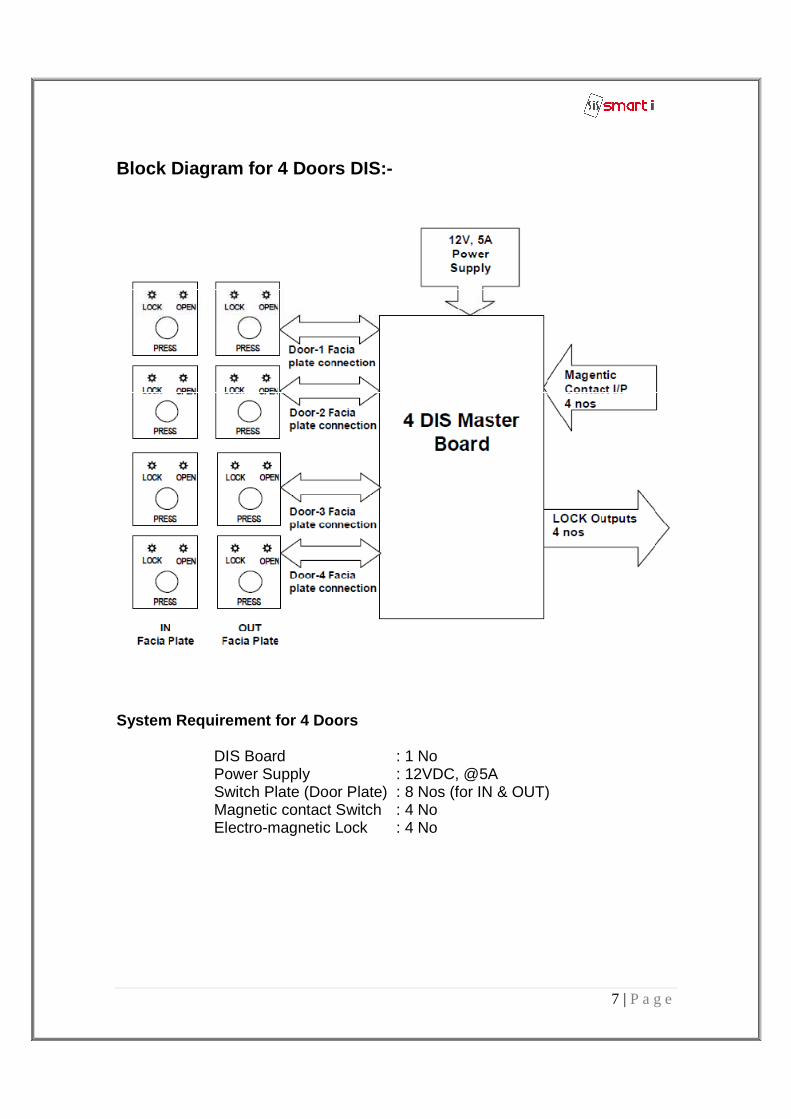
Block Diagram for 4 Doors DIS:-
System Requirement for 4 Doors
DIS Board : 1 No Power Supply : 12VDC, @5A Switch Plate (Door Plate) : 8 Nos (for IN & OUT) Magnetic contact Switch : 4 No Electro-magnetic Lock : 4 No
8 | P a g e
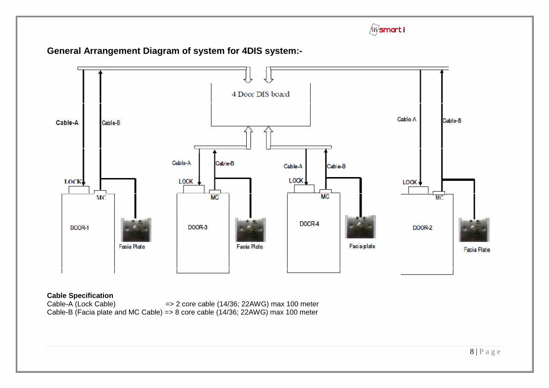
General Arrangement Diagram of system for 4DIS syst em:-
Cable Specification Cable-A (Lock Cable) => 2 core cable (14/36; 22AWG) max 100 meter Cable-B (Facia plate and MC Cable) => 8 core cable (14/36; 22AWG) max 100 meter
9 | P a g e
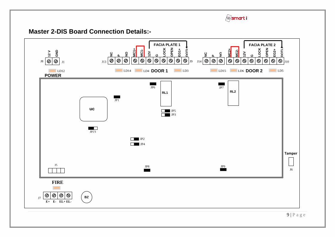
Master 2-DIS Board Connection Details:-
RL1 RL2
DOOR 1 DOOR 2 POWER
BZ
NC
P
N
O
MC
1+
MC
1-
12V
G
LO
CK
O
PE
N
EG
1+
DO
TL1
NC
P
N
O
MC
2+
MC
2-
12V
G
LO
CK
O
PE
N
EG
2+
DO
TL2
uc
12 V
GN
D
Tamper
JP1
JP23
J5
JP2
JP4
JP8
JP6 JP7
JP5 JP3
JP9
FACIA PLATE 1 FACIA PLATE 2
J1 J13 J9 J14 J10
J6
E+ E- EL+ EL- J7
J8
FIRE
LD12 LD4 LD14 LD3 LD6 LD15 LD5
10 | P a g e
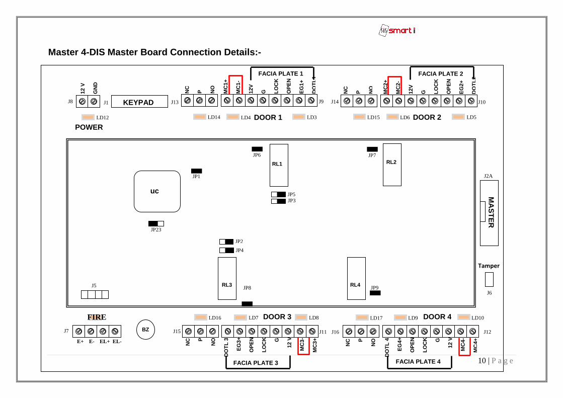
Master 4-DIS Master Board Connection Details:-
RL1 RL2
RL4 RL3
DOOR 1 DOOR 2
DOOR 3 DOOR 4
KEYPAD
POWER
MA
ST
ER
BZ
NC
P
N
O
MC
1+
MC
1-
12V
G
LO
CK
O
PE
N
EG
1+
DO
TL1
NC
P
N
O
MC
2+
MC
2-
12V
G
LO
CK
O
PE
N
EG
2+
DO
TL2
NC
P
NO
DO
TL
4
EG
4+
O
PE
N
L
OC
K
G
1
2 V
MC
4-
MC
4+
NC
P
NO
DO
TL
3
E
G3+
OP
EN
LO
CK
G
1
2 V
M
C3-
MC
3+
uc
12 V
GN
D
Tamper
JP1
JP23
J5
JP2
JP4
JP8
JP6 JP7
JP5 JP3
JP9
FACIA PLATE 1 FACIA PLATE 2
FACIA PLATE 3 FACIA PLATE 4
J1 J13 J9 J14 J10
J2A
J6
J12 J16 J11 J15
E+ E- EL+ EL-
J7
J8
FIRE
LD12 LD4 LD14 LD3 LD6 LD15 LD5
LD9 LD7 LD8 LD16 LD10 LD17
11 | P a g e
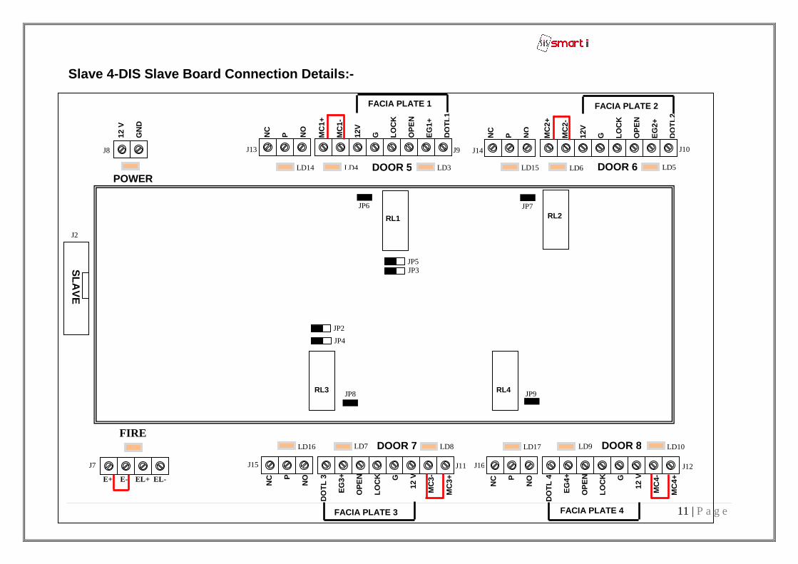
Slave 4-DIS Slave Board Connection Details:-
RL1 RL2
RL4 RL3
DOOR 5 DOOR 6
DOOR 7 DOOR 8
POWER
NC
P
N
O
MC
1+
MC
1-
12V
G
LO
CK
O
PE
N
EG
1+
DO
TL1
NC
P
N
O
MC
2+
MC
2-
12V
G
LO
CK
O
PE
N
EG
2+
DO
TL2
NC
P
NO
DO
TL
4
EG
4+
O
PE
N
L
OC
K
G
1
2 V
MC
4-
MC
4+
NC
P
NO
DO
TL
3
E
G3+
OP
EN
LO
CK
G
1
2 V
M
C3-
MC
3+
12 V
GN
D
JP2
JP4
JP8
JP6 JP7
JP5 JP3
JP9
FACIA PLATE 1 FACIA PLATE 2
FACIA PLATE 3 FACIA PLATE 4
J13 J9 J14 J10
J12 J16 J11 J15
SLA
VE
E+ E- EL+ EL-
J7
J2
J8
FIRE
LD14 LD3 LD15 LD5
LD8 LD16 LD10 LD17
LD4 LD6
LD9 LD7
12 | P a g e
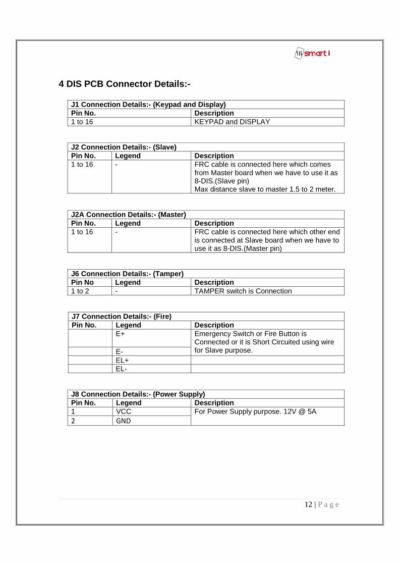
4 DIS PCB Connector Details:-
J1 Connection Details: - (Keypad and Display) Pin No. Description 1 to 16 KEYPAD and DISPLAY
J2 Connection Details: - (Slave) Pin No. Legend Description 1 to 16 - FRC cable is connected here which comes
from Master board when we have to use it as 8-DIS.(Slave pin) Max distance slave to master 1.5 to 2 meter.
J2A Connection Details: - (Master) Pin No. Legend Description 1 to 16 - FRC cable is connected here which other end
is connected at Slave board when we have to use it as 8-DIS.(Master pin)
J6 Connection Details: - (Tamper) Pin No Legend Description 1 to 2 - TAMPER switch is Connection
J7 Connection Details: - (Fire) Pin No. Legend Description E+ Emergency Switch or Fire Button is
Connected or it is Short Circuited using wire for Slave purpose. E-
EL+ EL-
J8 Connection Details: - (Power Supply) Pin No. Legend Description 1 VCC For Power Supply purpose. 12V @ 5A 2 GND
13 | P a g e
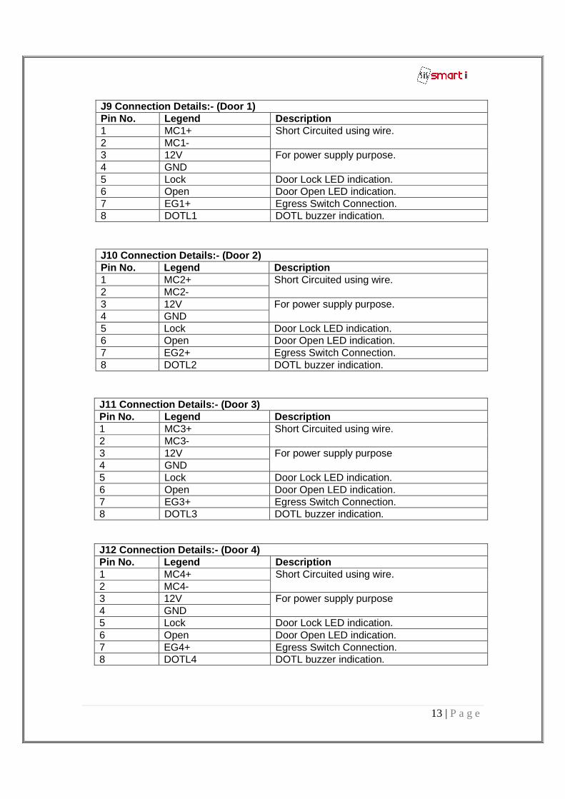
J9 Connection Details: - (Door 1) Pin No. Legend Description 1 MC1+ Short Circuited using wire. 2 MC1- 3 12V For power supply purpose. 4 GND 5 Lock Door Lock LED indication. 6 Open Door Open LED indication. 7 EG1+ Egress Switch Connection. 8 DOTL1 DOTL buzzer indication.
J10 Connection Details: - (Door 2) Pin No. Legend Description 1 MC2+ Short Circuited using wire. 2 MC2- 3 12V For power supply purpose. 4 GND 5 Lock Door Lock LED indication. 6 Open Door Open LED indication. 7 EG2+ Egress Switch Connection. 8 DOTL2 DOTL buzzer indication.
J11 Connection Details: - (Door 3) Pin No. Legend Description 1 MC3+ Short Circuited using wire. 2 MC3- 3 12V For power supply purpose 4 GND 5 Lock Door Lock LED indication. 6 Open Door Open LED indication. 7 EG3+ Egress Switch Connection. 8 DOTL3 DOTL buzzer indication.
J12 Connection Details: - (Door 4) Pin No. Legend Description 1 MC4+ Short Circuited using wire. 2 MC4- 3 12V For power supply purpose 4 GND 5 Lock Door Lock LED indication. 6 Open Door Open LED indication. 7 EG4+ Egress Switch Connection. 8 DOTL4 DOTL buzzer indication.
14 | P a g e
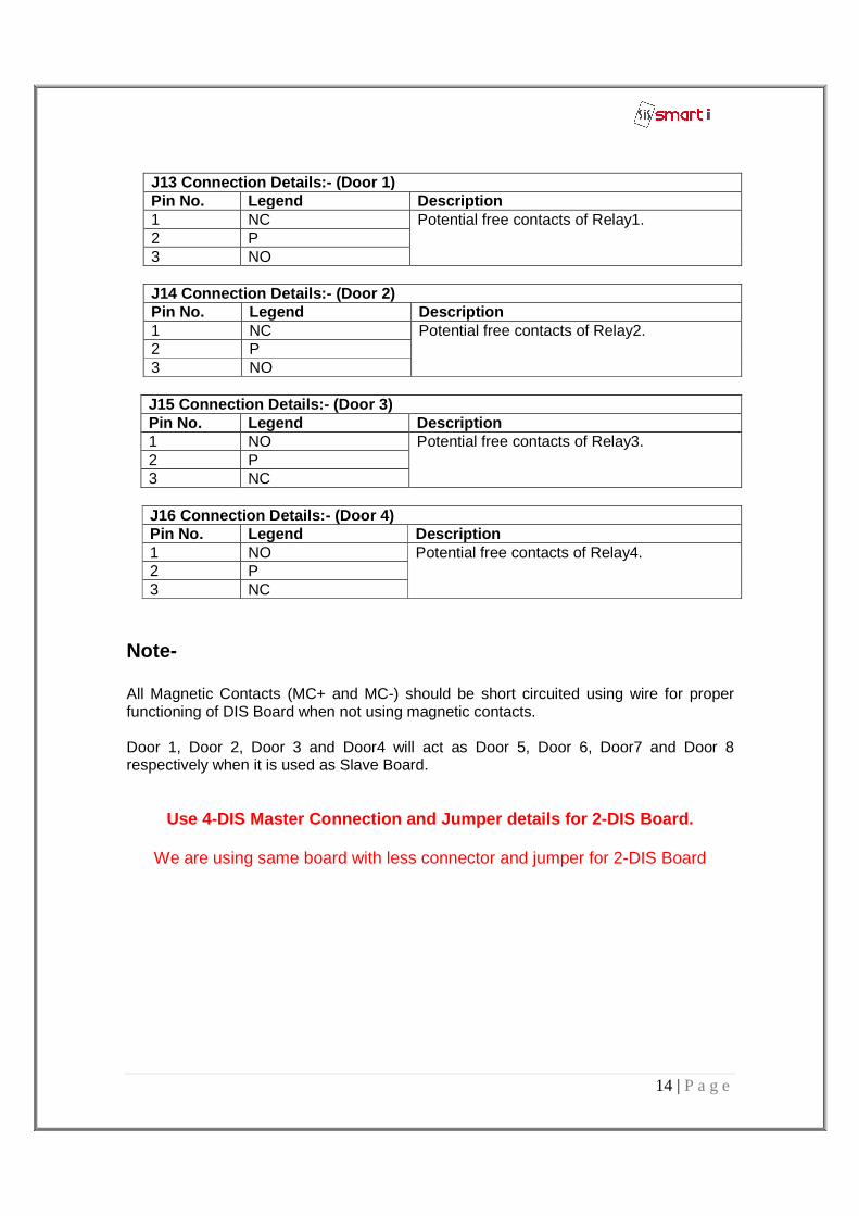
J13 Connection Details: - (Door 1) Pin No. Legend Description 1 NC Potential free contacts of Relay1. 2 P 3 NO
J14 Connection Details: - (Door 2) Pin No. Legend Description 1 NC Potential free contacts of Relay2. 2 P 3 NO
J15 Connection Details: - (Door 3) Pin No. Legend Description 1 NO Potential free contacts of Relay3. 2 P 3 NC
J16 Connection Details: - (Door 4) Pin No. Legend Description 1 NO Potential free contacts of Relay4. 2 P 3 NC
Note- All Magnetic Contacts (MC+ and MC-) should be short circuited using wire for proper functioning of DIS Board when not using magnetic contacts. Door 1, Door 2, Door 3 and Door4 will act as Door 5, Door 6, Door7 and Door 8 respectively when it is used as Slave Board.
Use 4-DIS Master Connection and Jumper details for 2-DIS Board.
We are using same board with less connector and jumper for 2-DIS Board
15 | P a g e
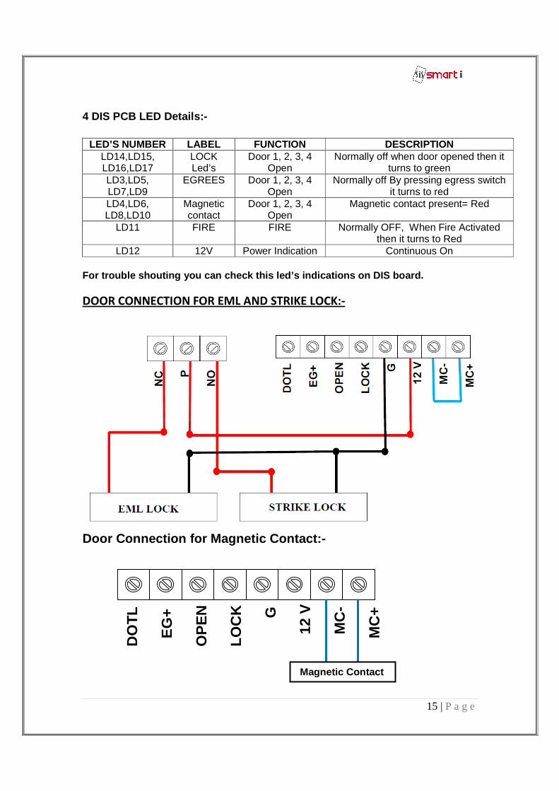
4 DIS PCB LED Details:-
LED’S NUMBER LABEL FUNCTION DESCRIPTION LD14,LD15, LD16,LD17
LOCK Led’s
Door 1, 2, 3, 4 Open
Normally off when door opened then it turns to green
LD3,LD5, LD7,LD9
EGREES Door 1, 2, 3, 4 Open
Normally off By pressing egress switch it turns to red
LD4,LD6, LD8,LD10
Magnetic contact
Door 1, 2, 3, 4 Open
Magnetic contact present= Red
LD11 FIRE FIRE Normally OFF, When Fire Activated then it turns to Red
LD12 12V Power Indication Continuous On For trouble shouting you can check this led’s indic ations on DIS board. DOOR CONNECTION FOR EML AND STRIKE LOCK:-
Door Connection for Magnetic Contact:-
D
OT
L
EG
+
OP
EN
LO
CK
G
1
2 V
M
C-
M
C+
Magnetic Contact
16 | P a g e
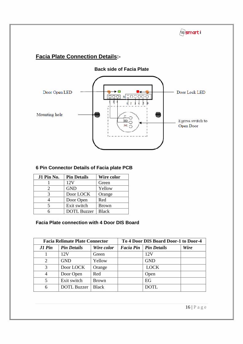
Facia Plate Connection Details :-
Back side of Facia Plate
6 Pin Connector Details of Facia plate PCB
Facia Plate connection with 4 Door DIS Board
J1 Pin No. Pin Details Wire color 1 12V Green 2 GND Yellow 3 Door LOCK Orange 4 Door Open Red 5 Exit switch Brown 6 DOTL Buzzer Black
Facia Relimate Plate Connector To 4 Door DIS Board Door-1 to Door-4 J1 Pin
No. Pin Details Wire color Facia Pin
No. Pin Details Wire
color 1 12V Green
12V 2 GND Yellow GND 3 Door LOCK
LED Orange LOCK
4 Door Open LED
Red Open 5 Exit switch Brown EG 6 DOTL Buzzer Black DOTL
17 | P a g e
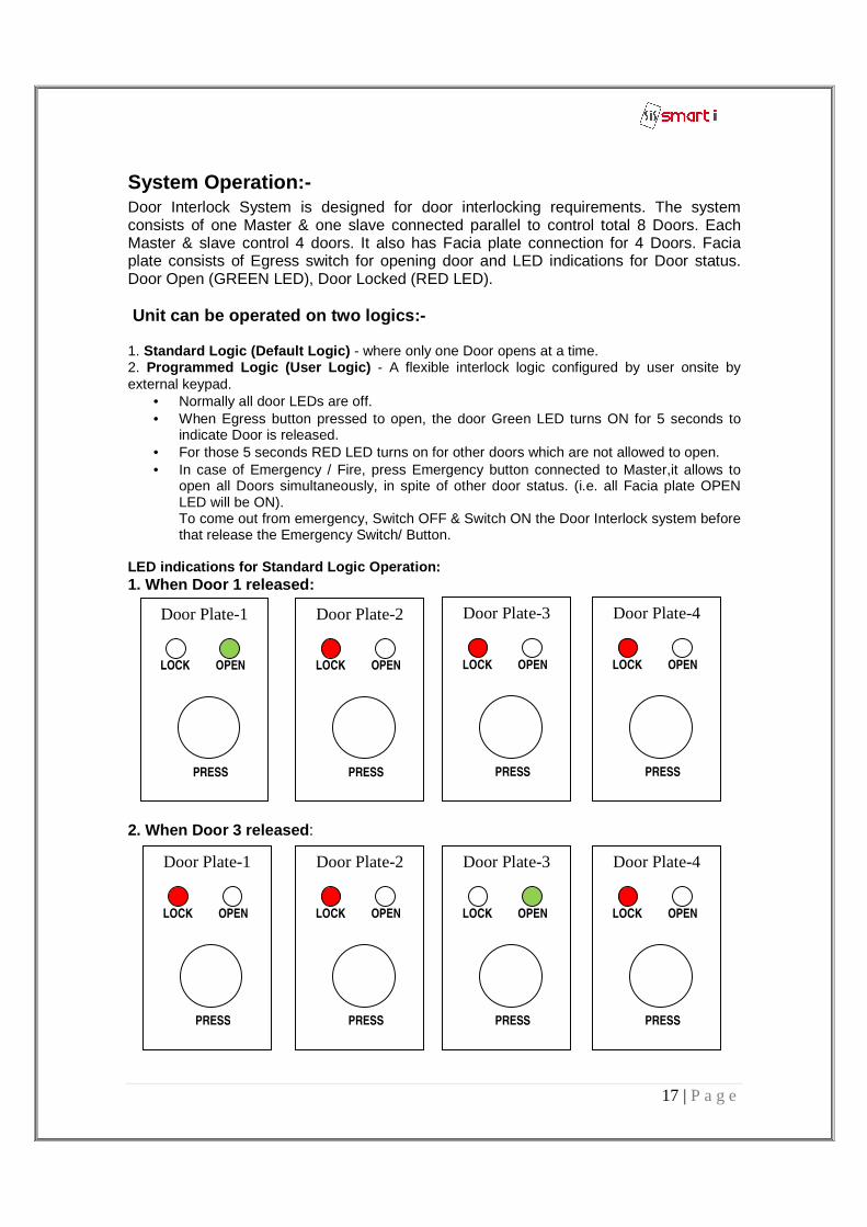
System Operation:- Door Interlock System is designed for door interlocking requirements. The system consists of one Master & one slave connected parallel to control total 8 Doors. Each Master & slave control 4 doors. It also has Facia plate connection for 4 Doors. Facia plate consists of Egress switch for opening door and LED indications for Door status. Door Open (GREEN LED), Door Locked (RED LED). Unit can be operated on two logics:- 1. Standard Logic (Default Logic) - where only one Door opens at a time. 2. Programmed Logic (User Logic) - A flexible interlock logic configured by user onsite by external keypad.
• Normally all door LEDs are off. • When Egress button pressed to open, the door Green LED turns ON for 5 seconds to
indicate Door is released. • For those 5 seconds RED LED turns on for other doors which are not allowed to open. • In case of Emergency / Fire, press Emergency button connected to Master,it allows to
open all Doors simultaneously, in spite of other door status. (i.e. all Facia plate OPEN LED will be ON). To come out from emergency, Switch OFF & Switch ON the Door Interlock system before that release the Emergency Switch/ Button.
LED indications for Standard Logic Operation: 1. When Door 1 released:
2. When Door 3 released :
Door Plate-1
LOCK OPEN
PRESS
Door Plate-2
LOCK OPEN
PRESS
Door Plate-3
LOCK OPEN
PRESS
Door Plate-4
LOCK OPEN
PRESS
Door Plate-3
LOCK OPEN
PRESS
Door Plate-2
LOCK OPEN
PRESS
Door Plate-4
LOCK OPEN
PRESS
Door Plate-1
LOCK OPEN
PRESS
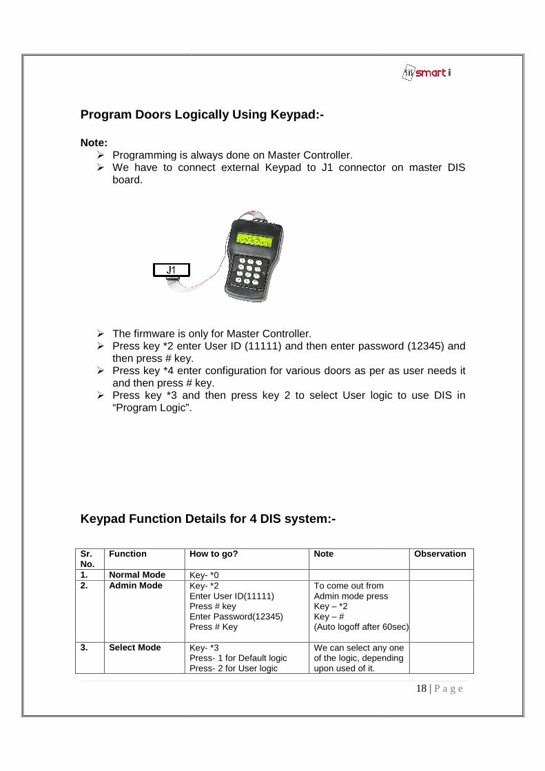
Program Doors Logically Us Note: � Programming is always done on Master Controller.� We have to connect
board.
� The firmware is only for Master Controller� Press key *2 enter
then press # key.� Press key *4 enter configuration for various doors as per as user needs it
and then press # key.� Press key *3 and then press key 2 to select User logic to use DIS in
“Program Logic”.
Keypad Function Details for 4 DIS system
Sr. No.
Function How to go?
1. Normal Mode Key2. Admin Mode Key
Enter User ID(11111)Press # keyEnter Password(12345)Press # Key
3. Select Mode KeyPressPress
Logically Us ing Keypad:-
Programming is always done on Master Controller. We have to connect external Keypad to J1 connector
The firmware is only for Master Controller. 2 enter User ID (11111) and then enter password (12345) and
then press # key. Press key *4 enter configuration for various doors as per as user needs it and then press # key. Press key *3 and then press key 2 to select User logic to use DIS in “Program Logic”.
Keypad Function Details for 4 DIS system :-
How to go? Note
Key- *0 Key- *2 Enter User ID(11111) Press # key Enter Password(12345) Press # Key
To come out from Admin mode pressKey – *2 Key – # (Auto logoff after 60sec)
Key- *3 Press- 1 for Default logic Press- 2 for User logic
We can select any one of the logic, depending upon used of it.
18 | P a g e
Keypad to J1 connector on master DIS
User ID (11111) and then enter password (12345) and
Press key *4 enter configuration for various doors as per as user needs it
Press key *3 and then press key 2 to select User logic to use DIS in
Observation
To come out from Admin mode press
(Auto logoff after 60sec)
We can select any one of the logic, depending
19 | P a g e
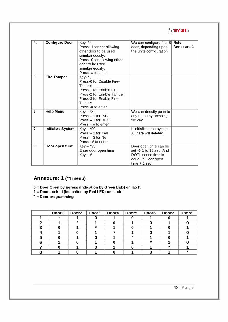
Annexure: 1 (*4 menu) 0 = Door Open by Egress (Indication by Green LED) o n latch. 1 = Door Locked (Indication by Red LED) on latch * = Door programming
4. Configure Door Key- *4 Press- 1 for not allowing other door to be used simultaneously. Press- 0 for allowing other door to be used simultaneously. Press- # to enter
We can configure 4 or 8 door, depending upon the units configuration
Refer Annexure:1
5 Fire Tamper Key- *5 Press-0 for Disable Fire-Tamper Press-1 for Enable Fire Press-2 for Enable Tamper Press-3 for Enable Fire-Tamper Press -# to enter
6 Help Menu Key – *8 Press – 1 for INC Press – 3 for DEC Press – # to enter
We can directly go in to any menu by pressing “#” key.
7 Initialize System Key – *90 Press – 1 for Yes Press – 3 for No Press– # to enter
It initializes the system. All data will deleted
8 Door open time Key – *95 Enter door open time Key – #
Door open time can be set � 1 to 98 sec. And DOTL sense time is equal to Door open time + 1 sec.
Door1 Door2 Door3 Door4 Door5 Door6 Door7 Door8 1 * 1 0 1 0 1 0 1 2 1 * 1 0 1 0 1 0 3 0 1 * 1 0 1 0 1 4 1 0 1 * 1 0 1 0 5 0 1 0 1 * 1 0 1 6 1 0 1 0 1 * 1 0 7 0 1 0 1 0 1 * 1 8 1 0 1 0 1 0 1 *
20 | P a g e
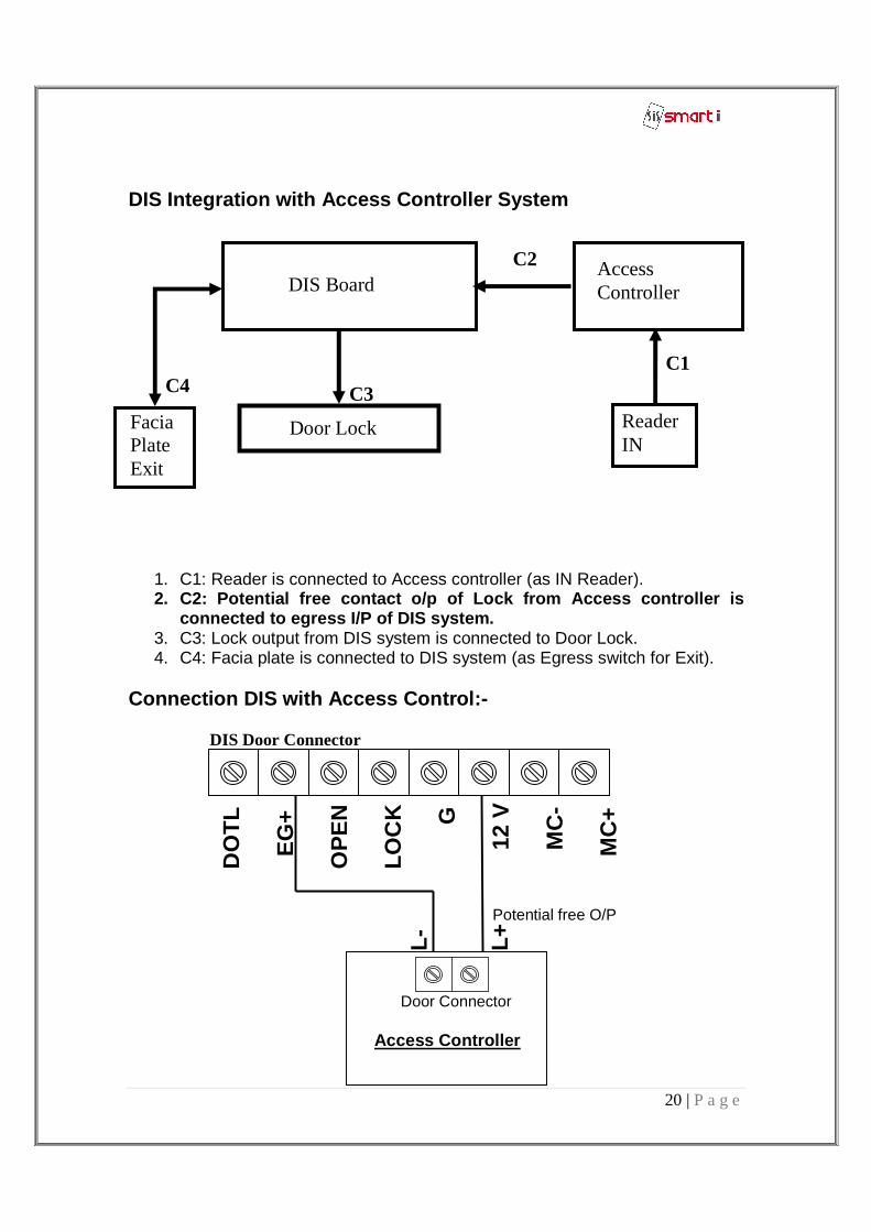
DIS Integration with Access Controller System
1. C1: Reader is connected to Access controller (as IN Reader). 2. C2: Potential free contact o/p of Lock from Acce ss controller is
connected to egress I/P of DIS system. 3. C3: Lock output from DIS system is connected to Door Lock. 4. C4: Facia plate is connected to DIS system (as Egress switch for Exit).
Connection DIS with Access Control:- DIS Door Connector
DIS Board Access Controller
Door Lock Facia Plate Exit
C1
C2
C3 C4
Reader IN
D
OT
L
EG
+
OP
EN
LO
CK
G
1
2 V
M
C-
M
C+
Door Connector Access Controller
L- L+
Potential free O/P