disassembly procedure - tim.id.autim.id.au/laptops/asus/w3000a.pdf · disassembly procedure w3a 3 -...
TRANSCRIPT

disassembly procedure
W3A 3 - 1
Disassembly Procedure Please follow the information provided in this section to perform the complete disassembly procedure of the notebook. Be sure to use proper tools described before.
SUS W3000A Series Notebook consists of various modules. This chapter describes the procedures for the complete notebook disassembly. In addition, in between procedures, the detailed disassembly procedure of individual modules will be provided for your service needs. The disassembly procedure consists of the following steps:
• Battery Module • HDD Module • Optical Drive Module • CPU Module • Second Memory Module • Mini PCI Module • Keyboard Module • First Memory Module • LCD Module • Top Case Module • Motherboard Module
Chapter
3
A

disassembly procedure
W3A 3 - 2
Battery Module The illustration below shows how to remove the battery module. 1. Press latch to open the battery module, then lift battery module away from the system.
HDD Module The illustrations below show how to remove the HDD module from the notebook. Removing HDD Module 1. Remove 1 screw (M2*4L(K)), then remove the HDD door.
2. Lift the hard disk module and disconnect the FPC then take away the hard disk module.
B A T T E R Y
H D D
M O D U L E
H D D
M O D U L E
R E M O V A L
M2*4L
disassembly procedure
W3A 3 - 3
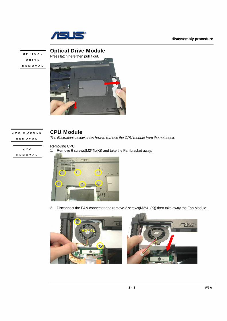
Optical Drive Module Press latch here then pull it out.
CPU Module The illustrations below show how to remove the CPU module from the notebook. Removing CPU 1. Remove 6 screws(M2*4L(K)) and take the Fan bracket away.
2. Disconnect the FAN connector and remove 2 screws(M2*4L(K)) then take away the Fan Module.
O P T I C A L
D R I V E
R E M O V A L
C P U M O D U L E
R E M O V A L
C P U
R E M O V A L
M2*4L

disassembly procedure
W3A 3 - 4
3. Remove the 4 screws (M2*4L(K)) upon the thermal module and take away the CPU heat sink module gently
4. Turn the non-removable screw here 180 degrees counter-clockwise to loosen the CPU and take the
CPU away
Note: If thermal module has no thermal pad on it, please plus a thermal pad on the CPU die before assembling.

disassembly procedure
W3A 3 - 5
Second Memory Module The W3000A Series Notebook does not have onboard RAM. There are two SO-DIMM sockets for installing SO-DIMM RAM. It can upgrade the total memory size up to 2GB with a 1GB module on each socket. Removing Memory module 1. Pull 2 latches 2. Pop the module up to a 45° angles, and then pulling out the module in that angle.
Wireless LAN Module This slot usually has Wireless LAN module when leaving the factory, this slot is for optional system upgrade. Removing Wireless LAN Module 1. Remove 1 screw (M2*4L(K)), then take the mini-PCI cover off.
2. Remove 2 Antenna cables from Wireless LAN Module
W I R E L E S S
L A N
M O D U L E
W I R E L E S S
L A N
R E M O V A L
S E C O N D
M E M O R Y
M O D U L E
M E M O R Y
R E M O V A L

disassembly procedure
W3A 3 - 6
3. Remove the Wireless LAN module by opening the 2 latches aside, which will pop the module up to an angle of 30°, then pull out the module in that angle just like memory module.
Keyboard Module The illustration of below shows how to remove the keyboard Removing Keyboard and Keyboard Cover 1. Remove 2 screws (M2*4L(K))
2. Unlock 3 keyboard latches then pull out the keyboard forward and lay the keyboard on the front side
then disconnect the FPC.
K E Y B O A R D
K / B C O V E R
R E M O V A L

disassembly procedure
W3A 3 - 7
First Memory Module 1. The first memory module is under keyboard. Push the memory cover to the left side and lift the
memory cover and open the two latches to pop up memory module at 45 degrees angle then pull it out.
LCD Module The illustrations below show how to remove and disassemble the LCD module. The module contains LCD panel, Inverter board, LCD Hinge bracket, Hinge cover, LCD front cover, LCD back cover 1. Remove 2 screws(M2*4L(K)) and FPC on top case and take away the Keyboard Cover.
2. Remove Coaxial cable and inverter cable
F I R S T
M E M O R Y
M O D U L E
R E M O V A L
L C D
M O D U L E
disassembly procedure
W3A 3 - 8
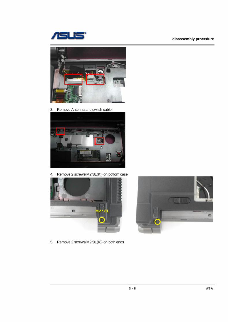
3. Remove Antenna and switch cable.
4. Remove 2 screws(M2*8L(K)) on bottom case
5. Remove 2 screws(M2*8L(K)) on both ends
M2*8L

disassembly procedure
W3A 3 - 9
6. Take away the LCD Module
Removing LCD Module 1. Remove 5 rubber pads and 5 screws(M2 x 4L) from LCD module.
2. Prying the inside edges of the top front bezel, then separate it from LCD back cover and take
L C D
R E M O V A L
M2*8L
disassembly procedure
W3A 3 - 10
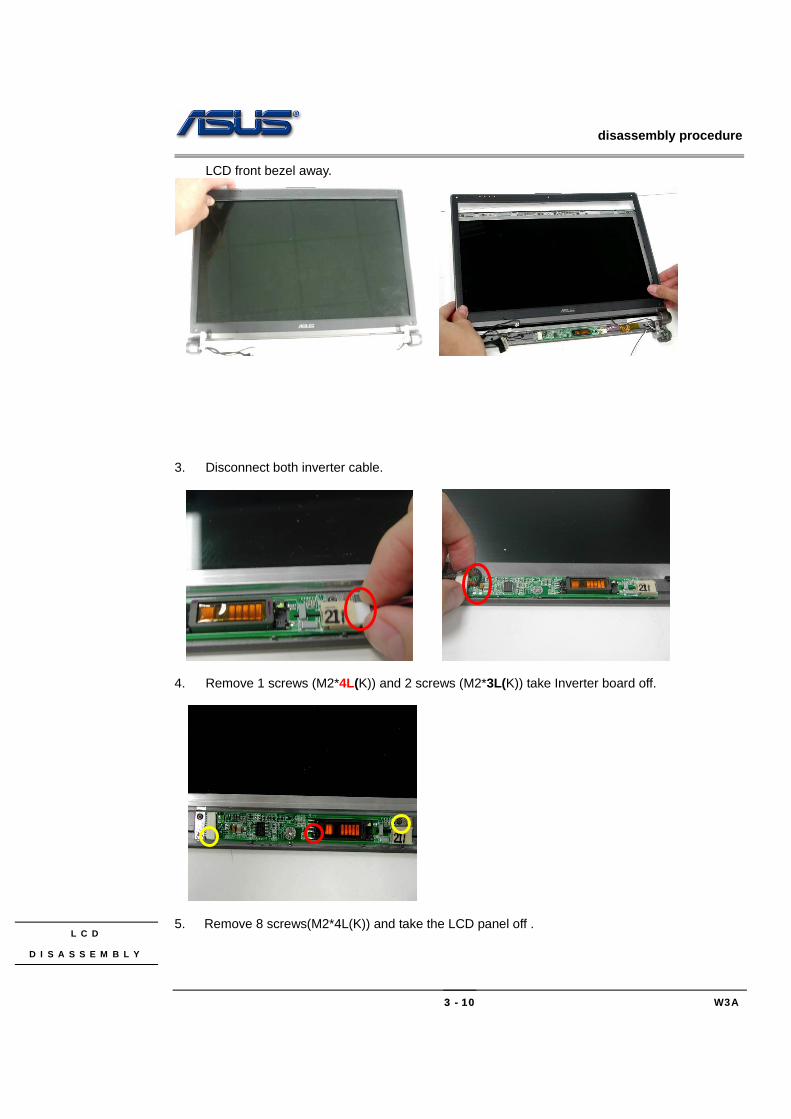
LCD front bezel away.
3. Disconnect both inverter cable.
4. Remove 1 screws (M2*4L(K)) and 2 screws (M2*3L(K)) take Inverter board off.
5. Remove 8 screws(M2*4L(K)) and take the LCD panel off . L C D
D I S A S S E M B L Y
disassembly procedure
W3A 3 - 11
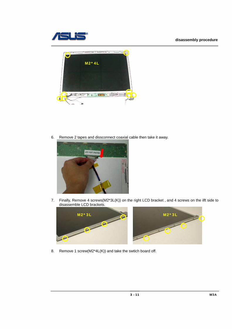
6. Remove 2 tapes and dissconnect coaxial cable then take it away.
7. Finally, Remove 4 screws(M2*3L(K)) on the right LCD bracket , and 4 screws on the ilft side to
disassemble LCD brackets.
8. Remove 1 screw(M2*4L(K)) and take the swtich board off.
M2*4L
M2*3L M2*3L
disassembly procedure
W3A 3 - 12
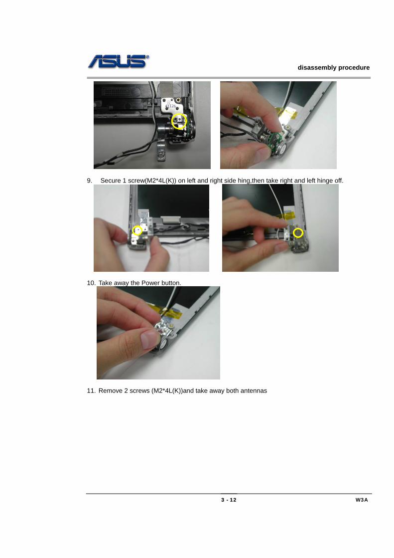
9. Secure 1 screw(M2*4L(K)) on left and right side hing,then take right and left hinge off.
10. Take away the Power button.
11. Remove 2 screws (M2*4L(K))and take away both antennas
disassembly procedure
W3A 3 - 13
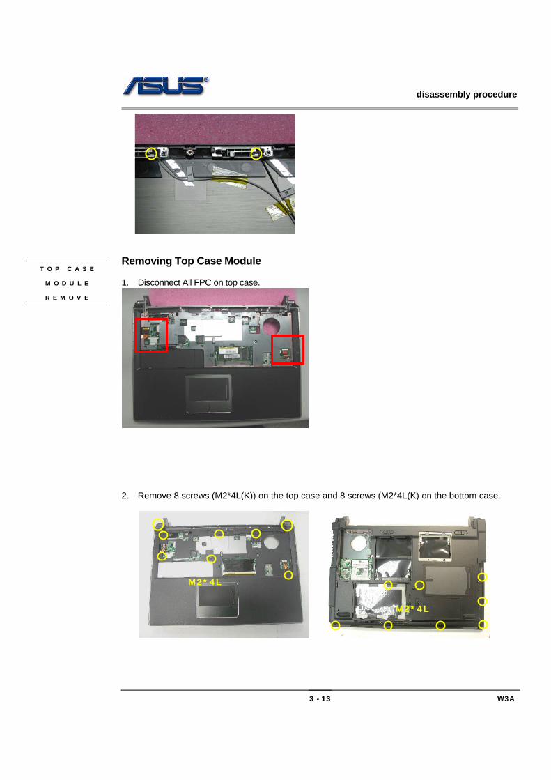
Removing Top Case Module 1. Disconnect All FPC on top case.
2. Remove 8 screws (M2*4L(K)) on the top case and 8 screws (M2*4L(K) on the bottom case.
T O P C A S E
M O D U L E
R E M O V E
M2*4L
M2*4L

disassembly procedure
W3A 3 - 14
3. Separate the top case module from the bottom case module.
4. Remove 4 screws(M2*4L(K)) and take away both speaker.
5. Disconnect touch pad FPC cables and remove 5 screws(M2*3L(K)) then take touch pad backet
off and take touch pad away.

disassembly procedure
W3A 3 - 15
6. Remove 6 scews (M2*2L(K)) and take away both side key modules
Motherboard module The illustrations below show how to disassemble and remove the Motherboard module, the blue tooth module and the modem module. Removing Motherboard Module 1. Disconnect the power cable
2. Remove 3 screws (M2*4L(K)) and take away the Motherboard Module from the left side.
M O T H E R B O A R D
M O D U L E
M D C
M O D U L E
R E M O V A L

disassembly procedure
W3A 3 - 16
3. Turn the mother board around, remove 2 screws (M2*4L(K)), disconnect the modem cable.
4. Remove the blue tooth module.
M2*4L
M2*4L
disassembly procedure
W3A 3 - 17
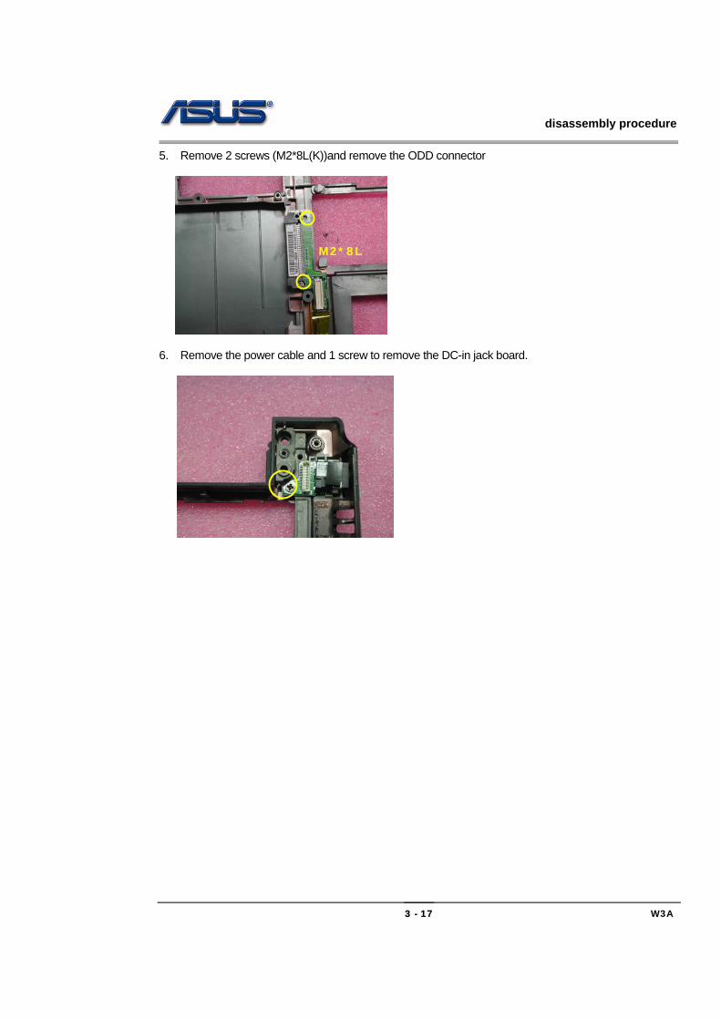
5. Remove 2 screws (M2*8L(K))and remove the ODD connector
6. Remove the power cable and 1 screw to remove the DC-in jack board.
M2*8L