digital projects - door lock - eit.lth.se · the aim of this project was to construct a door lock...
TRANSCRIPT
Digital projects - Door lockEITF40 - LTH
George Ryrstedt - dt07gr1
Fredrik Annerstedt - dt07fa8
Advisor: Bertil Lindvall
March 1, 2011
Abstract
The aim of this project was to construct a door lock that responded to
a set of prede�ned knock sequences. The idea was that it is all too easy
to forget your keys and for example lock yourself out of your apartment.
Having to remember a certain sequence instead is much easier and elim-
inates the need for any physical keys. For additional security Bluetooth
reception of the owners cellphone is also required.
2

Contents
1 Introduction 4
1.1 About the course . . . . . . . . . . . . . . . . . . . . . . . . . . . 41.2 About the project . . . . . . . . . . . . . . . . . . . . . . . . . . 4
2 Requirements 4
3 Hardware 4
3.1 Arduino BT with ATMega168 . . . . . . . . . . . . . . . . . . . . 43.2 LCD Hitachi 44780 . . . . . . . . . . . . . . . . . . . . . . . . . . 53.3 H-bridge and motor . . . . . . . . . . . . . . . . . . . . . . . . . 53.4 Other hardware . . . . . . . . . . . . . . . . . . . . . . . . . . . . 5
4 Software design 5
5 Execution 6
6 Results 6
7 Discussion 6
A Schematics 9
B Source code 9
3
1 Introduction
1.1 About the course
The goal of the course is to simulate real industrial development. More speci�-cally to learn the necessary skills needed in order to build a working prototypefor further production. First and foremost it provides an insight on how soft-ware and hardware integrates and work together. The course is without anyscheduled lectures and requires much individual work and time management.
1.2 About the project
The project in this report is a door look that responds to a preprogrammed se-quence of knocks. The intended function is that the user knocks the sequence onthe door and if it is correct the door should open automatically. To make it easierfor the user the knocks should not be based on an absolute time frame. Ratherthe relative time between each knock is the important factor. In case someoneaccidentally happens to produce the correct sequence the users cellphone mustbe in Bluetooth range for the door to open. The lock is reprogrammable andhave a LCD-screen which outputs status messages and debug information.
2 Requirements
In the beginning of the project a basic requirements speci�cation was created.
• The lock should be constantly ready to receive the key sequence.
• The lock should only accept the correct knock sequence, based on relativetiming.
• The lock should only open the door if both the knock sequence and theprede�ned cellphone is in range.
• The lock should be easily reprogrammable with a new knock sequence.
• The prede�ned cellphone should be easily changeable.
• The lock should have a LCD to display current state and other informa-tion.
• The lock should have status LEDs to indicate its current state.
3 Hardware
3.1 Arduino BT with ATMega168
The whole project is based around an AVR ATMega168 microprocessor whichis integrated in an Arduino board. The ATMega is a complete microcontrollerwith RAM, �ash memory and EEPROM. The initial thought was to just usethe ATMega16 but the Arduino was chosen for its simple Bluetooth integration.Otherwise Bluetooth would probably have been too complex to integrate inthe speci�ed timeframe. Both the ATMega and the Arduino board are well
4

known as among hobbyists which makes it easy to �nd documentation andother information. The Arduino also makes it possible to do everything inC++ instead of just using C.
3.2 LCD Hitachi 44780
The display consists of spaces for 2x16 characters and is based on the Hitachi44780 chip. This project uses it for outputting information about the state ofthe lock. Also debug information in the development phase of the project.
3.3 H-bridge and motor
An ordinary LEGO-motor is used in the project to simulate the opening of thelock. When the door opens the motor �rst rotates in one direction for a coupleof seconds then wait for the user to get inside and then rotates in the otherdirection, simulating the locking. To be able to turn the motor both ways asimple H-bridge is used. This also enables the ability to connect an externalpower source to the motor so that in a real world scenario a more powerfulmotor can be used.
3.4 Other hardware
A trimmable potentiometer (trimpot) is used to vary the contrast on the LCD.LEDs are used to indicate basic states, but was mostly used during development.
Buttons are used to simulate door knocks and to reprogram the device. Theoriginal idea was to use a piezo speaker to detect knocks but due to availabilitybuttons are used instead. There were unexpected problems with button de-bouncing and a low pass �lter consisting of resistors and capacitors had to beimplemented.
4 Software design
The �rst problem with the software was the fact that the user had to be ableto set a knock sequence of variable length. This immediately ruled out usinga standard array as if the user entered a knock sequence that was longer thenthe array was designed to hold it would result in unde�ned and potentiallydangerous behavior. To get around this a simple vector class was implementedthat internally stored the values in an array giving O(1) fetches of data and O(n)insertion time. The worst case insertion time occurs when an object is placedafter the last position in the array, in which case a new and bigger array wascreated. The old one copies to the new one and the old one gets deleted. Thesecond problem was how to implement code to detect when a knock occurred, orthe programming button was pressed. Had polling been used the program mightpotentially miss the event if it occurred faster then the main loops executiontime. Instead the ATMega's two available interrupts bound to the two eventsand store the time the knock occurred or to enter programming mode based onthe event that occurred. If the event was of a knock type the "knockDetected"-function was called and the current time stored in the knocks vector. Howeverif the programming button was pressed the knock handling routine was changed
5
from the default "knockDetected" to "programKnocks" which essentially doesthe same thing as "knockDetected" except instead of storing the time values inthe "knocks "vector it stores them in the "openSeq" vector. The main loop ofthe program continuously runs and checks whether the "knocks" and "openSeq"vector are equal in length; if they are it compares the relative time intervals thatthe knocks occurred at in the array and if they are equal to each other withinthe de�ned tolerances, the door opens. The software was implemented usingC++ as there were no hard realtime constraints on the system and the featuresof C++ enabled design choices that would not have been available had C beenused e.g. implementing a custom vector class.
5 Execution
The original plan was to build a complete system which would be ready tobe installed in a standard door. However due to several mechanical obstaclesthe project was scaled down somewhat. The actual �tting of the lock andeverything surrounding that e.g. the motor torque required to open a lock werenot problems that felt relevant to the course. It was decided to skip those partsand replace them with simulated components in order to focus on the electronicparts and the software. A LEGO-motor was used to simulate a real high torquemotor but it could easily be replaced with a real one should anyone wish toimplement the system in an actual door.
A piezo speaker would have provided the input for the knock sequence butsince no one was available and and it was possible to do it just as well withbuttons, no further time was spent investigating that. Buttons replaced thepiezo entirely and while a few possible problems disappeared with that othersappeared instead. A substantial amount of time was spent trying to eliminatedebouncing. The buttons would trigger irregularly and in e�ect became totallyuseless in that state. However after a simple low-pass �lter was implementedbetter results were noted. They were still not up to the task of emulating knocksthough. With additional code to further eliminate debouncing an acceptablereliability was reached. Just as with the motor the buttons should be somewhateasily replaceable with a pizeo speaker in a real system.
6 Results
The prototype is working as intended and simulates opening of the door whenthe correct sequence is entered. It should be relatively easy to modify thisprototype to a working production model. The basic operation is there onlythe form factor and some of the components need revision. It satis�es all of therequirements that were set up in the beginning. In addition to this it is alsopossible to open the door with only the speci�ed cellphone.
7 Discussion
During the project several problems where encountered in regards to the ana-log components. The �rst problem we encountered was that sometimes whenpressing the button repeatedly in rapid succession the software would register
6
two button presses when the button was only pressed once. The �rst solutionto this problem we tried was implement a low pass �lter between the buttonand the input pin, this reduced the problem some what but the software wouldstill sometimes register one too many presses so to argument the hardware so-lution a software �x was implemented where button presses occurring withinless then 100ms from the last registered one are ignored. The second majorhardware problem we encountered was that at what appeared to random timesthe Arduino stopped responding to input or giving output as well as behavingerratically when buttons were pressed with no apparent pattern. After a whilewe realized that this was occurring every time we tried to run the motor throughthe H-bridge and due to the induced current spike the Arduino entered an un-de�ned state, the solution to this was as simple as adding a capacitor betweenground and Vcc before the H-bridge.
7
References
[1] AVR ATMega16http://www.eit.lth.se/�leadmin/eit/courses/edi021/datablad/Processors/ATmega16.pdf
[2] Hitachi 44780http://www.eit.lth.se/�leadmin/eit/courses/edi021/datablad/Display/hd44780.pdf
[3] Arduino BThttp://arduino.cc/en/Main/ArduinoBoardBluetooth
8
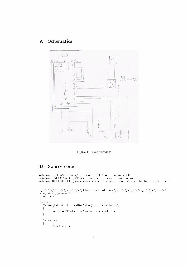
A Schematics
Figure 1: Basic overview
B Source code
#de f i n e TOLERANCE 0.5 // t o l e r an c e i e 0 . 5 = plus /minus 50%#de f i n e TIMEOUT 5000 //Timeout between knocks in m i l l i s e c ond s#de f i n e DEBOUNCE 100 //minimum amount o f time to wait between button p r e s s e s in ms
/////////////////////////// Class d e c l a r a t i o n s //////////////////////////////////template<typename T>c l a s s Vector{pub l i c :
Vector ( i n t s i z e ) : mySize ( s i z e ) , myLastValue(−1){
array = (T ∗) mal loc (mySize ∗ s i z e o f (T) ) ;}
~Vector ( ){
f r e e ( array ) ;
9

}
void s e t ( i n t po s i t i on , T value ){
i f ( p o s i t i o n > myLastValue ){
myLastValue = po s i t i o n ;}i f ( p o s i t i o n > (mySize − 1) ){
T∗ tmp = array ;array = (T ∗) mal loc ( ( p o s i t i o n + 1) ∗ s i z e o f (T) ) ;memcpy( array , tmp , mySize ) ;f r e e (tmp ) ;mySize = po s i t i o n + 1 ;
}array [ p o s i t i o n ] = value ;
}
void push (T value ){
s e t ( ( myLastValue + 1) , va lue ) ;}
T get ( i n t p o s i t i o n ){ re turn array [ p o s i t i o n ] ; }
i n t s i z e ( ){ re turn (myLastValue + 1 ) ; }
T la s tVa lue ( ){ re turn array [ myLastValue ] ; }
void c l e a r ( ){ myLastValue = −1; }
p r i va t e :i n t myLastValue ;i n t mySize ;T∗ array ;
} ;
///////////////////////////////////////////////////////////////////////////////////
v o l a t i l e i n t motorstate = LOW;v o l a t i l e bool programMode = 0 ;i n t knockpin=2;i n t programpin=3;i n t motorEnablePin = 8 ;i n t motorForwardsPin = 7 ;i n t motorBackwardsPin = 6 ;i n t l edp in =13;i n t l edS ta t e = LOW;Vector<f l o a t > knocks ( 1 0 ) ;Vector<f l o a t > openSeq ( 1 0 ) ;i n t nothing = 0 ;
void setup ( ) {a t t a ch In t e r rup t (0 , knockDetected , FALLING) ;a t t a ch In t e r rup t (1 , enterProgramMode , FALLING) ;pinMode ( programpin , INPUT) ;
10
pinMode ( knockpin , INPUT) ;pinMode ( ledpin , OUTPUT) ;pinMode (motorEnablePin , OUTPUT) ;pinMode (motorForwardsPin , OUTPUT) ;pinMode (motorBackwardsPin , OUTPUT) ;S e r i a l . begin (115200 ) ;S e r i a l . p r i n t l n (" Started " ) ;openSeq . push ( 0 ) ;openSeq . push ( 1 ) ;openSeq . push ( 2 ) ;
}
void loop ( ) {// S e r i a l . p r i n t l n ( S e r i a l . l i s t ( ) . l ength ) ;i f ( S e r i a l . a v a i l a b l e ( ) > 0)
{byte data = S e r i a l . read ( ) ;i f ( data == 'o ' )
{openDoor ( ) ;
}}
i f ( openSeq . s i z e ( ) != 0 && knocks . s i z e ( ) == openSeq . s i z e ( ) ){openDoor ( ) ;/∗S e r i a l . p r i n t (" running de t e c t i on code\n " ) ;togg leLed ( ) ; // g ive some debugging outputf l o a t d i s tance Input ;f l o a t d i s tanceExpected ;f l o a t totalTimeInput = knocks . l a s tVa lue ( ) − knocks . get ( 0 ) ;f l o a t totalTimeExpected = openSeq . l a s tVa lue ( ) − openSeq . get ( 0 ) ;i n t c o r r e c t = 0 ;i n t nmbrDatapoints = openSeq . s i z e ( ) − 1 ;f o r ( i n t i = 0 ; i < nmbrDatapoints ; i++)
{d i s tance Input = ( knocks . get ( i + 1) − knocks . get ( i ) ) / totalTimeInput ;d i s tanceExpected = ( openSeq . get ( i + 1) − openSeq . get ( i ) ) / totalTimeExpected ;// S e r i a l . p r i n t (" Distnance " ) ;// S e r i a l . p r i n t ( d i s tanceInput , 3 ) ;// S e r i a l . p r i n t (" expected value : " ) ;// S e r i a l . p r i n t ( distanceExpected , 3 ) ;// S e r i a l . p r i n t ("\n " ) ;i f ( d i s tance Input > ( distanceExpected ∗ TOLERANCE) && di s tance Input < ( distanceExpected ∗ (1 + TOLERANCE) ) ){c o r r e c t++;}
e l s e{break ;}
}i f ( c o r r e c t == nmbrDatapoints )
{openDoor ( ) ;
}∗/
knocks . c l e a r ( ) ; // r e s e t p o s i t i o n to r eenab l e knockDetect ion}
}
void knockDetected ( )
11
{
f l o a t time = m i l l i s ( ) ;i f ( knocks . s i z e ( ) < openSeq . s i z e ( ) && ( knocks . s i z e ( ) == 0 | | time > ( knocks . l a s tVa lue ( ) + DEBOUNCE) ) )
{S e r i a l . p r i n t l n (" knock detec ted " ) ;i f ( knocks . s i z e ( ) != 0 && time > ( knocks . l a s tVa lue ( ) + TIMEOUT)) // i f t imeout s i n c e l a s t knock then s t a r t from the beg inning
{S e r i a l . p r i n t l n ("New sequence " ) ;knocks . c l e a r ( ) ;
}knocks . push ( time ) ;}
}
void programKnocks ( ){
f l o a t time = m i l l i s ( ) ;i f ( openSeq . s i z e ( ) == 0 | | time < ( openSeq . l a s tVa lue ( ) + TIMEOUT))
{i f ( time > ( openSeq . l a s tVa lue ( ) + DEBOUNCE))
{S e r i a l . p r i n t l n (" adding knock " ) ;openSeq . push ( time ) ;
}}
e l s e{S e r i a l . p r i n t l n (" e x i t i n g programming mode " ) ;a t t a ch In t e r rup t (0 , knockDetected , FALLING) ;knockDetected ( ) ;}
}
void enterProgramMode ( ){
S e r i a l . p r i n t l n (" Enter ing programming mode " ) ;openSeq . c l e a r ( ) ;knocks . c l e a r ( ) ; // prevent loop code from running once we r e c i v i e a knock or twoa t ta ch In t e r rup t (0 , programKnocks , FALLING) ;
}
void togg leLed ( ){
l edS ta t e = ! l edS ta t e ;d i g i t a lWr i t e ( ledpin , l edS ta t e ) ;
}
void openDoor ( ){i n t waitDelay = 5000 ;d i g i t a lWr i t e (motorForwardsPin , HIGH) ;d i g i t a lWr i t e (motorEnablePin , HIGH) ;de lay ( waitDelay ) ;d i g i t a lWr i t e (motorEnablePin , LOW) ;d i g i t a lWr i t e (motorForwardsPin , LOW) ;de lay ( waitDelay ) ;d i g i t a lWr i t e (motorBackwardsPin , HIGH) ;d i g i t a lWr i t e (motorEnablePin , HIGH) ;de lay ( waitDelay ) ;d i g i t a lWr i t e (motorEnablePin , LOW) ;d i g i t a lWr i t e (motorBackwardsPin , LOW) ;
}
12