diagnostic and troubleshooting for golf car with … s. vineyard avenue ontario, ca 91761...
TRANSCRIPT

1551 S. Vineyard Avenue Ontario, CA 91761
909-923-1973
Diagnostic and Troubleshooting
For Golf Car with NON “E” Controller Software Version 1426 and UP
Revision: A Date: 11-30-17

Diagnostics
Diagnostics information can be obtained by observing the fault codes issued by the Status LED’s or as displayed on the Spyglass. See Table below for a summary of LED display formats.
The 1311 programmer will display all faults that are currently set as well as a history of the faults that have been set since the history log was last cleared. The 1311 displays the faults by name.
Summary of LED display formats
The two LEDs have four different display modes, indicating the type of information they are providing.
Display Status Neither LED Illuminated Controller is not powered on; or
vehicle has dead battery; or severe damage
Yellow LED flashing Controller is operating normally. Yellow and red LEDs both on solid Controller is in Flash program mode
Red LED on solid Watchdog failure or no software
loaded. Cycle KSI to restart, and if necessary load software.
Red LED and yellow LED flashing
alternately Controller has detected a fault. 2-digit code flashed by yellow LED identifies the specific fault; one or two flashes by red LED indicate whether first or second code digit will follow.
The pair of LEDs built into the controller (one red, one yellow) produce flash codes displaying all the currently set faults in a repeating cycle. Each code consists of two digits. The red LED flashes once to indicate that the first digit of the code will follow; the yellow LED then flashes the appropriate number of times for the first digit. The red LED flashes twice to indicate that the second digit of the code

will follow; the yellow LED flashes the appropriate number of times for the second digit.
Example: Battery Undervoltage (code 23). In the Fault menu of the 1311 programmer, the words Undervoltage Cutback will be displayed; the real-time battery voltage is displayed in the Monitor menu (“Keyswitch Voltage”).The controller’s two LEDs will display this repeating pattern:
RED YELLOW RED YELLOW ✱ ✲ ✲ ✱ ✱ ✲ ✲ ✲
(first digit) (2) (second digit) (3)
With this software package, not all of the codes below will be displayed on the Spyglass or enGage VII. We have only utilized faults that are pertinent to our software package.

Troubleshooting
The troubleshooting chart below provides the following information on all the controller faults:
• fault code • fault name as displayed on the programmer’s LCD • the effect of the fault • possible causes of the fault • fault set conditions • fault clear conditions
Whenever a fault is encountered and no wiring or vehicle fault can be found, shut off KSI and turn it back on to see if the fault clears. If it does not, shut off KSI and remove the 35-pin connector. Check the connector for corrosion or damage, clean it if necessary, and re-insert it.

Troubleshooting Chart
Golf Car Controller Faults (NON "E") Controllers
Code PROGRAMMER LCD DISPLAY
EFFECT OF FAULT POSSIBLE CAUSE SET/CLEAR CONDITIONS
12
Controller Overcurrent ShutdownMotor;
ShutdownMainContactor; ShutdownEMBrake; ShutdownThrottle;
FullBrake; ShutdownPump.
1) External short of phase U, V, or W motor connections 2) Motor parameters are mis-tuned 3) Controller defective 4) Speed encoder noise problems.
Set: Phase current exceeded the current measurement limit Clear: Cycle KSI
13
Current Sensor Fault ShutdownMotor;
ShutdownMainContactor; ShutdownEMBrake; ShutdownThrottle;
FullBrake; ShutdownPump.
1) Leakage to vehicle frame from phase U, V, or W (short in motor stator) 2) Controller defective
Set: Controller current sensors have invalid reading Clear: Cycle KSI
14
Precharge Failed ShutdownMotor;
ShutdownMainContactor; ShutdownEMBrake; ShutdownThrottle;
FullBrake; ShutdownPump.
1) External load on capacitor bank (B+ connection terminal) that prevents the capacitor bank from charging
Set: Precharge failed to charge the capacitor bank to KSI voltage Clear: Cycle Interlock input or use VCL function Enable_Precharge()
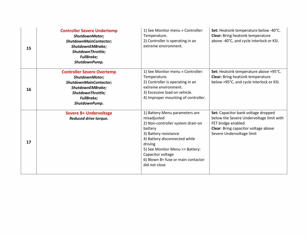
15
Controller Severe Undertemp ShutdownMotor;
ShutdownMainContactor; ShutdownEMBrake; ShutdownThrottle;
FullBrake; ShutdownPump.
1) See Monitor menu » Controller: Temperature. 2) Controller is operating in an extreme environment.
Set: Heatsink temperature below -40°C. Clear: Bring heatsink temperature above -40°C, and cycle interlock or KSI.
16
Controller Severe Overtemp ShutdownMotor;
ShutdownMainContactor; ShutdownEMBrake; ShutdownThrottle;
FullBrake; ShutdownPump.
1) See Monitor menu » Controller: Temperature. 2) Controller is operating in an extreme environment. 3) Excessive load on vehicle. 4) Improper mounting of controller.
Set: Heatsink temperature above +95°C. Clear: Bring heatsink temperature below +95°C, and cycle interlock or KSI.
17
Severe B+ Undervoltage Reduced drive torque.
1) Battery Menu parameters are misadjusted 2) Non-controller system drain on battery 3) Battery resistance 4) Battery disconnected while driving 5) See Monitor Menu >> Battery: Capacitor voltage 6) Blown B+ fuse or main contactor did not close
Set: Capacitor bank voltage dropped below the Severe Undervoltage limit with FET bridge enabled Clear: Bring capacitor voltage above Severe Undervoltage limit

18
Severe B+ Overvoltage ShutdownMotor;
ShutdownMainContactor; ShutdownEMBrake; ShutdownThrottle;
FullBrake; ShutdownPump.
1) See Monitor menu >> Battery: Capacitor Voltage 2) Battery menu parameters are misadjusted 3) Battery resistance too high for given regen current 4) Battery disconnected while regen braking
Set: Capacitor bank voltage exceeded the Severe Overvoltage limit with FET bridge enabled Clear: Bring capacitor voltage below Severe Overvoltage limit and then cycle KSI
22
Controller Overtemp Cutback Reduced drive and brake
torque.
1) See Monitor menu >> Controller: Temperature 2) Controller is performance-limited at this temperature 3) Controller is operating in an extreme environment 4) Excessive load on vehicle 5) Improper mounting of controller
Set: Heatsink temperature exceeded by 85°C Clear: Bring heatsink temperature below 85°C
23
B+ Undervoltage Cutback Reduced drive torque.
1) Normal operation. Fault shows that the batteries need recharging. Controller performance is limited at this voltage. 2) Battery parameters are misadjusted 3) Non-controller system drain on battery 4) Battery resistance too high 5) Battery disconnected while driving 6) See Monitor Menu >> Battery: Capacitor voltage 7) Blown B+ fuse or main contactor did not close
Set: Capacitor bank voltage dropped below the Undervoltage limit with the FET bridge enabled Clear: Bring capacitor voltage below the undervoltage limit

24
B+ Overvoltage Cutback Reduced brake torque.
1) Normal operation. Fault shows that regen braking currents elevated the battery voltage during regen braking. Controller is performance limited at this voltage. 2) Battery parameters are misadjusted 3) Battery resistance too high for given regen current 4) Battery disconnected while regen braking 5) See Monitor Menu >> Battery: Capacitor voltage
Set: Capacitor bank voltage exceeded the Overvoltage limit with the FET bridge enabled Clear: Bring capacitor voltage below the Overvoltage limit
25
5V Supply Failure None, unless a fault action
is programmed in VCL.
1) External load impedance on the +5V supply (pin 26) is too low 2) See Monitor menu >> outputs: 5 Volts and Ext Supply Current
Set: +5V supply (pin 26) outside the +5V +/- 10% range Clear: Bring voltage within range
26
Digital Out 6 Overcurrent Digital Output 6 driver
will not turn on.
1. External load impedance on Digital Output 6 driver (pin 19) is too low.
Set: Digital Output 6 (pin 19) current exceeded 15 mA. Clear: Remedy the overcurrent cause and use the VCL function Set_DigOut() to turn the driver on again.
27
Digital Out 7 Overcurrent Digital Output 7 driver
will not turn on.
1) External load impedance on Digital Output 7 driver (pin 20) is too low.
Set: Digital Output 7 (pin 20) current exceeded 15 mA. Clear: Remedy the overcurrent cause and use the VCL function Set_DigOut() to turn the driver on again.
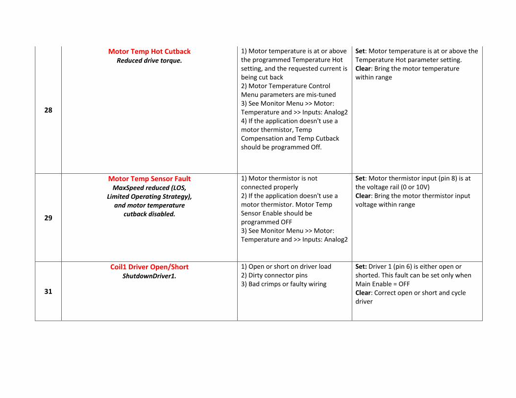
28
Motor Temp Hot Cutback Reduced drive torque.
1) Motor temperature is at or above the programmed Temperature Hot setting, and the requested current is being cut back 2) Motor Temperature Control Menu parameters are mis-tuned 3) See Monitor Menu >> Motor: Temperature and >> Inputs: Analog2 4) If the application doesn't use a motor thermistor, Temp Compensation and Temp Cutback should be programmed Off.
Set: Motor temperature is at or above the Temperature Hot parameter setting. Clear: Bring the motor temperature within range
29
Motor Temp Sensor Fault MaxSpeed reduced (LOS,
Limited Operating Strategy), and motor temperature
cutback disabled.
1) Motor thermistor is not connected properly 2) If the application doesn't use a motor thermistor. Motor Temp Sensor Enable should be programmed OFF 3) See Monitor Menu >> Motor: Temperature and >> Inputs: Analog2
Set: Motor thermistor input (pin 8) is at the voltage rail (0 or 10V) Clear: Bring the motor thermistor input voltage within range
31
Coil1 Driver Open/Short ShutdownDriver1.
1) Open or short on driver load 2) Dirty connector pins 3) Bad crimps or faulty wiring
Set: Driver 1 (pin 6) is either open or shorted. This fault can be set only when Main Enable = OFF Clear: Correct open or short and cycle driver

31
Main Open/Short ShutdownMotor;
ShutdownMainContactor; ShutdownEMBrake; ShutdownThrottle;
FullBrake; ShutdownPump.
1) Open or short on driver load 2) Dirty connector pins 3) Bad crimps or faulty wiring
Set: Main contactor driver (pin 6) is either open or shorted. This fault can be set only when Main Enable = ON Clear: Correct open or short, and cycle driver
32
Coil2 Driver Open/Short ShutdownDriver2.
1) Open or short on driver load. 2) Dirty connector pins. 3) Bad crimps or faulty wiring.
Set: Driver 2 (pin 5) is either open or shorted. This fault can be set only when EM Brake Type = 0. Clear: Correct open or short, and cycle driver.
32
EMBrake Open/Short ShutdownEMBrake; ShutdownThrottle;
FullBrake.
1) Open or short on driver load. 2) Dirty connector pins. 3) Bad crimps or faulty wiring.
Set: Electromagnetic brake driver (pin 5) is either open or shorted. This fault can be set only when EM Brake Type > 0. Clear: Correct open or short, and cycle driver.
33
Coil3 Driver Open/Short ShutdownDriver3.
1) Open or short on driver load. 2) Dirty connector pins. 3) Bad crimps or faulty wiring.
Set: Driver 3 (pin 4) is either open or shorted. Clear: Correct open or short, and cycle driver.
34
Coil4 Driver Open/Short ShutdownDriver4.
1) Open or short on driver load. 2) Dirty connector pins. 3) Bad crimps or faulty wiring.
Set: Driver 4 (pin 3) is either open or shorted. Clear: Correct open or short, and cycle driver.

35
PD Open/Short ShutdownPD.
1) Open or short on driver load. 2) Dirty connector pins. 3) Bad crimps or faulty wiring.
Set: Proportional driver (pin 2) is either open or shorted. Clear: Correct open or short, and cycle driver.
36
Encoder Fault ShutdownEMBrake; ShutdownThrottle.
1) Motor encoder failure 2) Bad crimps or faulty wiring 3) See Monitor menu >> Motor: Motor RPM
Set: Motor encoder phase failure detected. Clear: Cycle KSI
36
Sin/Cos Sensor Fault ShutdownEMBrake; ShutdownThrottle.
1) SPMSM motor characterization not completed or poorly matched to motor. 2) Sin/cos feedback sensor failure. 3) Bad crimps or faulty wiring. 4) See Monitor menu » Motor: Sin Input A and Sin Input B. 5) See Monitor menu » Motor: Motor RPM.
Set: Sin/cos sensor output failure detected. Clear: Cycle KSI.
37
Motor Open ShutdownMotor;
ShutdownMainContactor; ShutdownEMBrake; ShutdownThrottle;
FullBrake; ShutdownPump.
1) Motor phase is open 2) Bad crimps or faulty wiring
Set: Motor phase U, V or W detected open Clear: Cycle KSI

38
Main Contactor Welded ShutdownMotor;
ShutdownMainContactor; ShutdownEMBrake; ShutdownThrottle;
FullBrake; ShutdownPump.
1) Main contactor tips are welded closed 2) Motor phase U or V is disconnected or open 3) An alternative voltage path (such as an external precharge resistor) is providing a current to the capacitor bank (B+ connection terminal)
Set: Just prior to the main contactor closing, the capacitor bank voltage (B+ connection terminal) was loaded for a short time and the voltage did not discharge Clear: Cycle KSI
39
Main Contactor Did Not Close ShutdownMotor;
ShutdownMainContactor; ShutdownEMBrake; ShutdownThrottle;
FullBrake; ShutdownPump.
1) Main contactor did not close 2) Main contactor tips are oxidized, burned, or not making good contact 3) External load on capacitor bank (B+ connection terminal) that prevents capacitor bank from charging 4) Blown B+ fuse
Set: With the main contactor commanded closed, the capacitor bank voltage (B+ connection terminal) did not charge to B+ Clear: Cycle KSI
41
Throttle Wiper High ShutdownThrottle.
1) See Monitor Menu >> Inputs: Throttle Pot 2) Throttle pot wiper voltage too high
Set: Throttle pot wiper (pin 16) voltage is higher than the high fault threshold (can be changed with the VCL function Setup_Pot_Faults()) Clear: Bring throttle pot wiper voltage below the fault threshold

42
Throttle Wiper Low ShutdownThrottle.
1) See Monitor Menu >> Inputs: Throttle Pot 2) Throttle pot wiper voltage too low
Set: Throttle pot wiper (pin 16) voltage is lower than the low fault threshold (can be changed with the VCL function Setup_Pot_Faults()) Clear: Bring throttle pot wipervoltage above the fault threshold
43
Pot2 Wiper High FullBrake.
1) See Monitor Menu >> Inputs: Pot2 Raw 2) Pot2 wiper voltage too high
Set: Pot2 wiper (pin 17) voltage is higher than the high fault threshold (can be changed with the VCL function Setup_Pot_Faults()) Clear: Bring Pot2 wiper voltage below the fault threshold
44
Pot2 Wiper Low FullBrake.
1) See Monitor Menu >> Inputs: Pot2 Raw 2) Pot2 wiper voltage too low
Set: Pot2 wiper (pin 17) voltage is lower than the low fault threshold (can be changed with the VCL function Setup_Pot_Faults()) Clear: Bring Pot2 wiper voltage above the fault threshold
45
Pot Low Overcurrent ShutdownThrottle;
FullBrake.
1) See Monitor Menu >> Outputs: Pot Low 2) Combined pot resistance connected to pot low is too low
Set: Pot low (pin 18) current exceeds 10mA Clear: Clear pot low overcurrent condition and cycle KSI

46
EEPROM Failure ShutdownMotor;
ShutdownMainContactor; ShutdownEMBrake; ShutdownThrottle; ShutdownInterlock; ShutdownDriver1; ShutdownDriver2; ShutdownDriver3; ShutdownDriver4;
ShutdownPD; FullBrake;
ShutdownPump.
1) Failure to write to EEPROM memory. This can be caused by EEPROM memory writes initiated by VCL, by the CAN bus, by adjusting parameters with the programmer, or by loading new software into the controller
Set: Controller operating system tried to write to EEPROM memory and failed. Clear: Download the correct software (OS) and matching parameter default settings into the controller and cycle KSI
47
HPD/Sequencing Fault ShutdownThrottle.
1. KSI, interlock, direction, and throttle inputs applied in incorrect sequence. 2. Faulty wiring, crimps, or switches KSI, interlock, direction, or throttle inputs.
Set: HPD (High Pedal Disable) or sequencing fault caused by incorrect sequence of KSI, interlock, direction, and throttle inputs. Clear: Reapply inputs in correct sequence.
47
Emer Rev HPD ShutdownThrottle; ShutdownEMBrake.
1) Emergency Reverse operation has concluded, but the throttle, forward and reverse inputs, and interlock have not been returned to neutral.
Set: At the conclusion of Emergency Reverse, the fault was set because various inputs were not returned to neutral. Clear: If EMR_Interlock = On, clear the interlock, throttle, and direction inputs. If EMR_Interlock = Off, clear the throttle and direction inputs.
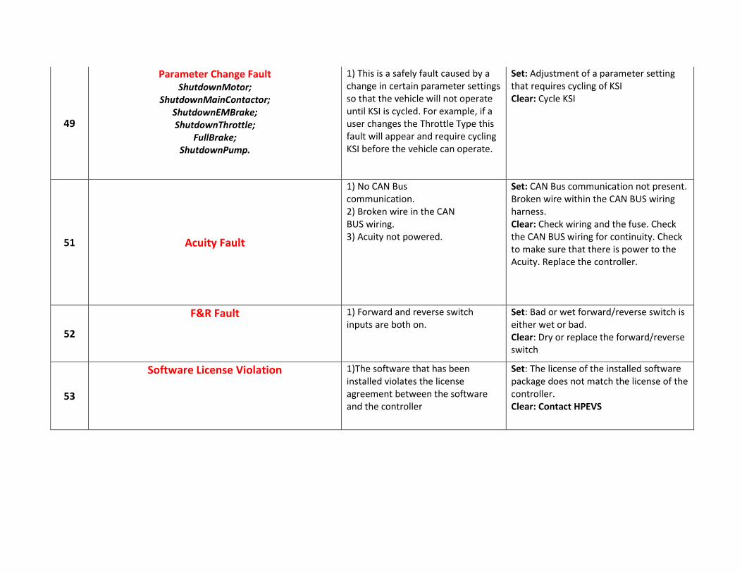
49
Parameter Change Fault ShutdownMotor;
ShutdownMainContactor; ShutdownEMBrake; ShutdownThrottle;
FullBrake; ShutdownPump.
1) This is a safely fault caused by a change in certain parameter settings so that the vehicle will not operate until KSI is cycled. For example, if a user changes the Throttle Type this fault will appear and require cycling KSI before the vehicle can operate.
Set: Adjustment of a parameter setting that requires cycling of KSI Clear: Cycle KSI
51 Acuity Fault
1) No CAN Bus communication. 2) Broken wire in the CAN BUS wiring. 3) Acuity not powered.
Set: CAN Bus communication not present. Broken wire within the CAN BUS wiring harness. Clear: Check wiring and the fuse. Check the CAN BUS wiring for continuity. Check to make sure that there is power to the Acuity. Replace the controller.
52
F&R Fault 1) Forward and reverse switch inputs are both on.
Set: Bad or wet forward/reverse switch is either wet or bad. Clear: Dry or replace the forward/reverse switch
53
Software License Violation 1)The software that has been installed violates the license agreement between the software and the controller
Set: The license of the installed software package does not match the license of the controller. Clear: Contact HPEVS

54
Tow Mode 1) If applicable, the tow mode switch has been activated, allowing for the golf car to be towed.
Set: Tow mode switch to tow or the tow/run switch has failed to an active state. Clear: Switch the Run/Tow switch to Run if desired. Check switch to make sure it is operating properly.
55
NO BMS COMMUNICATION 1) BMS communication has stopped or never started
Set: BMS communication fault detected Clear: Check CAN BUS wiring and connectors for loose or recessed pins in the connector or cut/broken wires. Restart system.
56
E7 Display NO COMMUNICATION 1)enGage VII communication has stopped or never started
Set: enGage VII communication fault detected Clear: Check CAN BUS wiring and connectors for loose or recessed pins in the connector or cut/broken wires. Possible issue with enGage VII; replace.
57
ACUITY COMMUNICATION FAULT 1) Acuity communication has stopped or never started
Set: Acuity communication fault detected Clear: Check CAN BUS wiring and connectors for loose or recessed pins in the connector or cut/broken wires. Replace Acuity
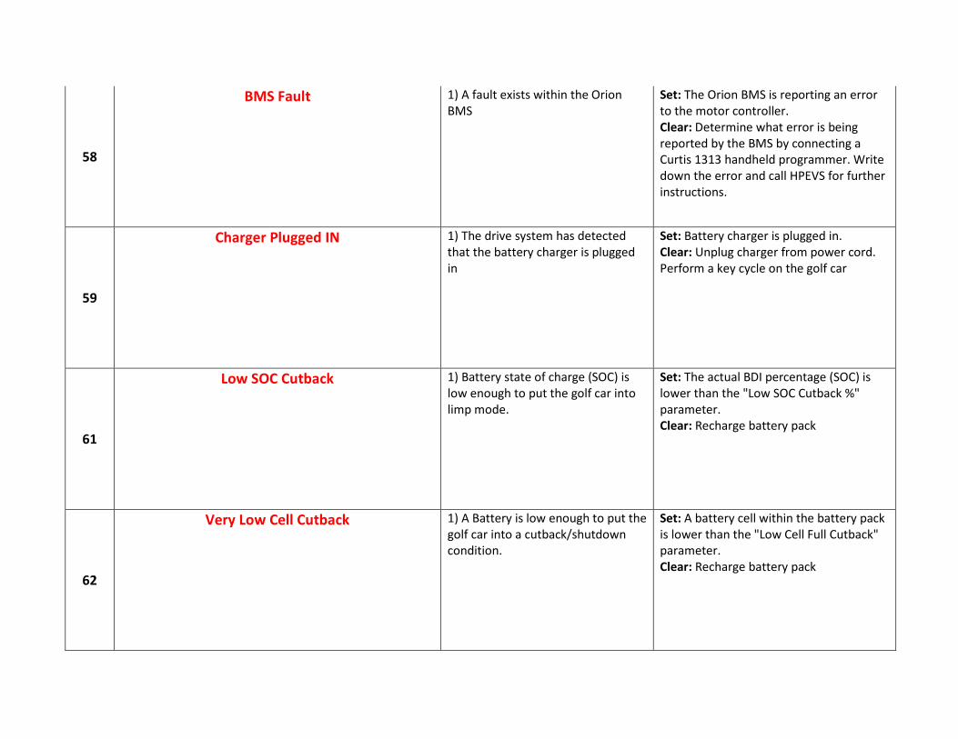
58
BMS Fault 1) A fault exists within the Orion BMS
Set: The Orion BMS is reporting an error to the motor controller. Clear: Determine what error is being reported by the BMS by connecting a Curtis 1313 handheld programmer. Write down the error and call HPEVS for further instructions.
59
Charger Plugged IN 1) The drive system has detected that the battery charger is plugged in
Set: Battery charger is plugged in. Clear: Unplug charger from power cord. Perform a key cycle on the golf car
61
Low SOC Cutback 1) Battery state of charge (SOC) is low enough to put the golf car into limp mode.
Set: The actual BDI percentage (SOC) is lower than the "Low SOC Cutback %" parameter. Clear: Recharge battery pack
62
Very Low Cell Cutback 1) A Battery is low enough to put the golf car into a cutback/shutdown condition.
Set: A battery cell within the battery pack is lower than the "Low Cell Full Cutback" parameter. Clear: Recharge battery pack

63
Shutdown 1) A battery condition exists where the BDI (SOC) is equal or less than 1% or a battery within the pack is below "Low Cell Full Cutback" for a short period of time. Note: Cart will shutdown
Set: Battery SOC is at or below 1% or a battery within the battery pack is below "Low Cell Full Cutback" parameter. Clear: Recharge battery pack
68
VCL Run Time Error ShutdownMotor;
ShutdownMainContactor; ShutdownEMBrake; ShutdownThrottle; ShutdownInterlock; ShutdownDriver1; ShutdownDriver2; ShutdownDriver3; ShutdownDriver4;
ShutdownPD; FullBrake;
ShutdownPump.
1) VCL code encountered a runtime VCL error 2) See Monitor Menu >> Controller: VCL Error Module and VCL Error. This error can then be compared to the runtime VCL module ID and error code definitions found in the specific OS system information file.
Set: Runtime VCL code error condition Clear: Edit VCL application software to fix this error condition; flash the new complied software and matching parameter defaults; cycle KSI

69
External Supply Out of Range 1) External load on the 5V and 12V supplies draws either too much or too little current 2) Fault Checking Menu parameters Ext Supply Max and Ext Supply Min are mis-tuned 3) See Monitor Menu >> Options: Ext Supply Current
Set: The external supply current (combined current used by the 5V supply [pin 26] and the 12V supply [pin 25]) is either greater than the upper current threshold or lower than the lower current threshold. The two thresholds are defined by the External Supply Max and External Supply Min parameter settings. Clear: Bring the external supply current within range
71
OS General ShutdownMotor;
ShutdownMainContactor; ShutdownEMBrake; ShutdownThrottle; ShutdownInterlock; ShutdownDriver1; ShutdownDriver2; ShutdownDriver3; ShutdownDriver4;
ShutdownPD; FullBrake;
ShutdownPump.
1) Internal controller fault. Set: Internal controller fault detected. Clear: Cycle KSI.

72
PDO Timeout ShutdownThrottle;
CAN NMT State set to Pre-operational.
1) Time between CAN PDO messages received exceeded the PDO Timeout Period.
Set: Time between CAN PDO messages received exceeded the PDO Timeout Period. Clear: Cycle KSI or receive CAN NMT message.
73
Stall Detected ShutdownEMBrake;
Control Mode changed to LOS (Limited Operating
Strategy).
1) Stalled Motor 2) Motor encoder failure 3) Bad crimps or faulty wiring 4) Problems with power supply for the motor encoder 5) See Monitor Menu >> Motor: Motor RPM
Set: No motor encoder movement detected Clear: Either cycle KSI or detect valid motor encoder signals while operating in LOS mode and return Throttle Command = 0 and Motor RPM = 0
77
Supervisor Fault ShutdownMotor;
ShutdownMainContactor; ShutdownEMBrake; ShutdownThrottle; ShutdownInterlock; ShutdownDriver1; ShutdownDriver2; ShutdownDriver3; ShutdownDriver4;
ShutdownPD; FullBrake;
ShutdownPump.
1) The Supervisor has detected a mismatch in redundant readings. 2) Internal damage to Supervisor microprocessor. 3) Switch inputs allowed to be within upper and lower thresholds for over over 100 milliseconds.
Set: Mismatched redundant readings; damaged Supervisor; illegal switch inputs. Clear: Check for noise or voltage drift in all switch inputs; check connections; cycle KSI.

78
Supervisor Incompatible ShutdownMotor;
ShutdownMainContactor; ShutdownEMBrake; ShutdownThrottle; ShutdownInterlock; ShutdownDriver1; ShutdownDriver2; ShutdownDriver3; ShutdownDriver4;
ShutdownPD; FullBrake;
ShutdownPump.
1) The main OS is not compatible with the Supervisor OS.
Set: Incompatible software. Clear: Load properly matched OS code or update the Supervisor code; cycle KSI.
82
Bad Calibrations ShutdownMotor;
ShutdownMainContactor; ShutdownEMBrake; ShutdownThrottle;
FullBrake; ShutdownPump.
1) Internal controller fault. Set: Internal controller fault detected. Clear: Correct fault; cycle KSI.
83
Driver Supply Fault ShutdownMotor;
ShutdownMainContactor; ShutdownEMBrake; ShutdownThrottle;
FullBrake; ShutdownPump.
1) Internal controller fault in the voltage supply for the driver circuits.
Set: Internal controller fault detected. Clear: Cycle KSI.

84
Following Error Fault ShutdownMotor;
ShutdownMainContactor; ShutdownEMBrake; ShutdownThrottle;
FullBrake; ShutdownPump.
1) Motor speed was detected not following the commanded speed trajectory within the programmed limits. 2) See Program menu » 1-Speed Mode » Speed Controller »Following Error Limit and Following Error Time. 3) See Monitor menu » Motor Tuning » Speed Error.
Set: With Control Mode Select = 0 or 1 Speed Mode Express or Speed Mode), motor speed error detected outside the the programmed limits. Clear: Cycle KSI.

87
Motor Characterization Fault ShutdownMotor;
ShutdownMainContactor; ShutdownEMBrake; ShutdownThrottle;
FullBrake; ShutdownPump.
1.) Motor characterization failed during characterization process. See Monitormenu » Controller: Motor Characterization Error for cause: 0=none 1=encoder signal seen, but step size not determined; set Encoder Step Size manually 2=motor temp sensor fault 3=motor temp hot cutback fault 4= controller overtemp cutback fault 5=controller undertemp cutback fault 6=undervoltage cutback fault 7=severe overvoltage fault 8=encoder signal not seen, or one or both channels missing 9=motor parameters out of characterization range. 20=sin/cos sensor not found. 21=phasing not detected. 22=sin/cos sensor characterization failure. 23=started characterization procedure while motor rotating.
Set: Motor characterization failed during the motor characterization process. Clear: Correct fault; cycle KSI. Notes: Errors 1 and 8 apply to ACIM motors only. Errors 20, 21, and 23 apply to SPMSM motors only. Errors indicate the motor characterization data is invalid, except in the case of Error 1.
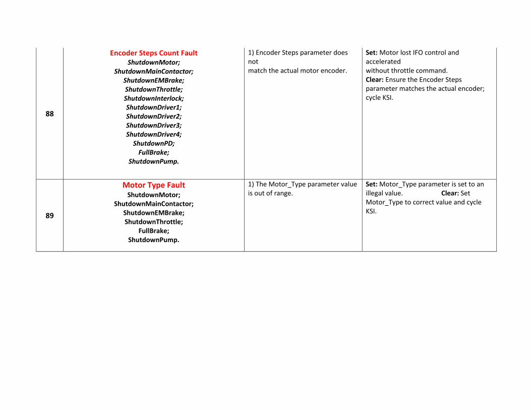
88
Encoder Steps Count Fault ShutdownMotor;
ShutdownMainContactor; ShutdownEMBrake; ShutdownThrottle; ShutdownInterlock; ShutdownDriver1; ShutdownDriver2; ShutdownDriver3; ShutdownDriver4;
ShutdownPD; FullBrake;
ShutdownPump.
1) Encoder Steps parameter does not match the actual motor encoder.
Set: Motor lost IFO control and accelerated without throttle command. Clear: Ensure the Encoder Steps parameter matches the actual encoder; cycle KSI.
89
Motor Type Fault ShutdownMotor;
ShutdownMainContactor; ShutdownEMBrake; ShutdownThrottle;
FullBrake; ShutdownPump.
1) The Motor_Type parameter value is out of range.
Set: Motor_Type parameter is set to an illegal value. Clear: Set Motor_Type to correct value and cycle KSI.

91
VCL/OS Mismatch ShutdownMotor;
ShutdownMainContactor; ShutdownEMBrake; ShutdownThrottle; ShutdownInterlock; ShutdownDriver1; ShutdownDriver2; ShutdownDriver3; ShutdownDriver4;
ShutdownPD; FullBrake;
ShutdownPump.
1) The VCL software in the controller does not match the OS software in the controller.
Set: VCL and OS software do not match; when KSI cycles, a check is made to verify that they match and a fault is issued when they do not. Clear: Download the correct VCL and OS software into the controller.
92
EM Brake Failed to Set ShutdownEMBrake; ShutdownThrottle;
Position Hold is engaged when Interlock=On.
1) Vehicle movement sensed after the EM Brake has been commanded to set. 2) EM Brake will not hold the motor from rotating.
Set: After the EM Brake was commanded to set and time has elapsed to allow the brake to fully engage, vehicle movement has been sensed. Clear: Activate the throttle.
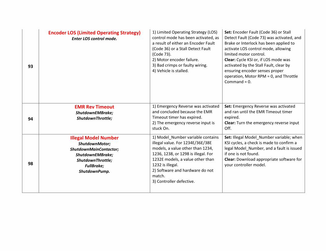
93
Encoder LOS (Limited Operating Strategy) Enter LOS control mode.
1) Limited Operating Strategy (LOS) control mode has been activated, as a result of either an Encoder Fault (Code 36) or a Stall Detect Fault (Code 73). 2) Motor encoder failure. 3) Bad crimps or faulty wiring. 4) Vehicle is stalled.
Set: Encoder Fault (Code 36) or Stall Detect Fault (Code 73) was activated, and Brake or Interlock has been applied to activate LOS control mode, allowing limited motor control. Clear: Cycle KSI or, if LOS mode was activated by the Stall Fault, clear by ensuring encoder senses proper operation, Motor RPM = 0, and Throttle Command = 0.
94
EMR Rev Timeout ShutdownEMBrake; ShutdownThrottle;
1) Emergency Reverse was activated and concluded because the EMR Timeout timer has expired. 2) The emergency reverse input is stuck On.
Set: Emergency Reverse was activated and ran until the EMR Timeout timer expired. Clear: Turn the emergency reverse input Off.
98
Illegal Model Number ShutdownMotor;
ShutdownMainContactor; ShutdownEMBrake; ShutdownThrottle;
FullBrake; ShutdownPump.
1) Model_Number variable contains illegal value. For 1234E/36E/38E models, a value other than 1234, 1236, 1238, or 1298 is illegal. For 1232E models, a value other than 1232 is illegal. 2) Software and hardware do not match. 3) Controller defective.
Set: Illegal Model_Number variable; when KSI cycles, a check is made to confirm a legal Model_Number, and a fault is issued if one is not found. Clear: Download appropriate software for your controller model.

99
Parameter Mismatch Fault ShutdownMotor;
ShutdownMainContactor; ShutdownEMBrake; ShutdownThrottle;
FullBrake; ShutdownPump.
1) Dual Motor Enable parameter set On and Control Mode Select parameter not set to 1 (Speed Mode Express) or 2 (Speed Mode). 2) Motor Technology and Feedback Type parameters do not match.
Set: When the Dual Drive software is enabled, the controller must be set to either Speed Mode Express or Speed Mode; otherwise this fault is set. Motor Technology=0 must be paired with Feedback Type=1, and Motor Technology=1 must be paired with Feedback Type=2; otherwise this fault is set. Clear: Adjust parameters to appropriate values and cycle KSI.