dhulapally, secunderabad (approved by aicte, affiliated to jntu...
TRANSCRIPT
1
(Approved by AICTE, Affiliated to JNTU, Hyderabad)
Department of Civil Engineering
CONCRETE & HIGHWAY MATERILALS
LAB MANUAL
ST. MARTIN’S ENGINEERING COLLEGE
DHULAPALLY, SECUNDERABAD

2
MANDATORY INSTRUCTIONS
1. Students should report to the labs concerned as per the timetable.
2. Record should be updated from time to time and the previous experiment must
be signed by the faculty in charge concerned before attending the lab.
3. Students who turn up late to the labs will in no case be permitted to perform the
experiment scheduled for the day.
4. After completion of the experiment, certification of the staff in-charge concerned
in the observation book is necessary.
5. Students should bring a notebook of about 100 pages and should enter the
readings/observations/results into the notebook while performing the
experiment.
6. The record of observations along with the detailed experimental procedure of the
experiment performed in the immediate previous session should be submitted
and certified by the staff member in-charge.
7. Not more than FIVE students in a group are permitted to perform the experiment
on a set up.
8. The group-wise division made in the beginning should be adhered to, and no mix
up of student among different groups will be permitted later.

3
9. The components required pertaining to the experiment should be collected from
Lab- in-charge after duly filling in the requisition form.
10. When the experiment is completed, students should disconnect the setup made
by them, and should return all the components/instruments taken for the
purpose.
11. Any damage of the equipment or burnout of components will be viewed
seriously either by putting penalty or by dismissing the total group of
students from the lab for the semester/year.
12. Students should be present in the labs for the total scheduled duration.
13. Students are expected to prepare thoroughly to perform the experiment before
coming to Laboratory.
14. Procedure sheets/data sheets provided to the students groups should be
maintained neatly and are to be returned after the experiment.
15. DRESS CODE:
i. Boys - Formal dress with tuck in and shoes.
ii. Girls - Formal dress (salwar kameez).
Iii. Apron in blue color for both boys and girls.
iii. Wearing of jeans is strictly prohibited

4

5
INDEX
I. TESTS ON ROAD AGGREGATES
1 Determination of Aggregate Crushing value
2 Determination of Aggregate Impact Value
3 Determination of Specific Gravity and water absorption.
4 Determination of Aggregate Attrition Value.
5 Determination of Aggregate Abrasion Value
6 Determination of Flakiness Index and Elongation Index of Coarse Aggregates.
II. TESTS ON BITUMINOUS MATERIALS
1 Penetration Test on Bitumen
2 Ductility Test on Bitumen
3 Softening point of Bitumen
4 Flash and Fire point Tests on Bitumen
III. TESTS ON CEMENT AND CONCRETE
1 Normal consistency of the cement
2 Determination of initial and final Setting Times of Standard Cement Paste.
3 Determination of Specific Gravity and Soundness of Cement.
4 Determination of Compressive Strength of Cement
5 Determination Workability of Fresh Concrete by Slump Cone Test, Compacting Factor Test
and Vee-Bee Consistometer method
6 Determination of Compressive Strength of Cubic Concrete Specimens
7 Determination of Bulking of Fine Aggregate
8 Non Destructive Testing on Concrete by Rebound hammer (for demonstration).
IV. TESTS BEYOND SYLLABUS COVERAGE
1 Marshal Stability Test for Bitumen or Asphalt mix

6
I. TESTS ON ROAD AGGREGATES

7
EXPERIMENT - 1: DETERMINATION OF AGGREGATE CRUSHING
VALUE
1.1 OBJECTIVE: This method of test covers the procedure for determining the aggregate
crushing value of coarse aggregate.
1.2 RESOURCES:
A 15 cm diameter open-ended steel cylinder, with plunger and base-plate, of the
general form and dimensions shown in Fig. ,A straight metal tamping rod, A balance
of capacity 3 kg, readable and accurate to one gram, IS Sieves of sizes 12.5, 10 and
2.36 mm, For measuring the sample, cylindrical metal measure of sufficient rigidity
to retain its form under rough usage and of the following internal dimensions:
Diameter 11.5 cm and Height 18.0 cm
1.3 PRECAUTIONS:
1. Aggregate should be saturated but with dry surface.
2. All care should be taken to avoid the loss of fines
3. Measure all quantities to the accuracy of 1 in 1000.
1.4 PROCEDURE:
1. The material for the standard test shall consist of aggregate passing a 12.5
mm IS Sieve and retained on a 10 mm IS Sieve, and shall be thoroughly
separated on these sieves before testing.
2. The aggregate shall be tested in a surface-dry condition. If dried by heating,
the period of drying shall not exceed four hours, the temperature shall be 100
to 110°C and the aggregate shall be cooled to room temperature before
testing.
3. The appropriate quantity may be found conveniently by filling the cylindrical
measure in three layers of approximately equal depth, each layer being
tamped 25 times with the rounded end of the tamping rod and finally leveled
off, using the tamping rod as a straight-edge.
4. The weight of material comprising the test sample shall be determined (Weight
A) and the same weight of sample shall be taken for the repeat test.
5. The apparatus, with the test sample and plunger in position, shall then be
placed between the platens of the testing machine and loaded at as uniform a
rate as possible so that the total load is reached in 10 minutes. The total load
shall be 400 kN.
6. The load shall be released and the whole of the material removed from the cylinder and sieved on a 2.36 mm IS Sieve for the standard test. The fraction passing the sieve shall be weighed (Weight B)

8
1.5 DIAGRAM:
1.6 TABLE AND CALCULATION:
The ratio of the weight of fines formed to the total sample weight in each test
shall be expressed as a percentage, the result being recorded to the first
decimal place: Aggregate Crushing Value - B/A X 100 A = weight in g of saturated surface - dry sample, B = weight in g of fraction passing through appropriate sieves
1.7 RESULT:
The aggregate crushing value of given sample of coarse aggregate is ……….. % The aggregate crushing value should not be more than 45 per cent for aggregate
used for concrete other than for wearing surfaces, and 30 per cent for concrete
used for wearing surfaces such a runways, roads and air field pavements.
1.8 PRE LAB QUESTIONS:
1. Explain aggregate crushing value how is this value expressed
2. Briefly explain the aggregate crushing value test procedure
3. What is the specified standard size of aggregates how is the aggregate crushing value of
non standard size aggregate evaluated
1.9 LAB ASSIGNMENT:
How do you determine the aggregate crushing value of the aggregate?

9
1.10 POST LAB QUESTIONS:
1. Aggregate crushing value of a material A is 40 and B is 25. Which on e is stronger/better
why
2. What are applications of aggregate crushing value test
3. What are the recommenced maximum values of aggregate crushing value for the
aggregates to be used in base and surface courses of cement concrete pavements
4. How is the crushing strength test carried out on cylindrical stone specimen? Why is the
test not carried out normally?

10
EXPERIMENT -2: DETERMINATION OF AGGREGATE IMPACT VALUE
2.1 OBJECTIVE: This method of test covers the procedure for determining the aggregate
impact value of coarse aggregate.
2.2 RESOURCES: An impact testing machine of the general form shown in Fig. 2 and
complying with the following:
1. A cylindrical steel cup of internal dimensions: Diameter 102 mm, Depth 50 mm
and not less than 6.3 mm thick 2. A metal hammer weighing 13.5 to 14.0 kg, the lower end of which shall be
cylindrical in shape, 100.0 mm in diameter and 5 cm long, with a 2 mm
chamfer at the lower edge, and case-hardened. The hammer shall slide freely
between vertical guides so arranged that the lower (cylindrical) part of the
hammer is above and concentric with the cup. 3. Means for raising the hammer and allowing it to fall freely between the vertical
guides from a height of 380.0 mm on to the test sample in the cup, and means
for adjusting the height of fall within 5 mm. 4. Sieves-The IS Sieves of sizes 12.5, 10 and 2.36 mm, Tamping Rod, balance of
capacity not less than 500 g, Oven etc.
2.3 PRECAUTIONS:
1. Proper sieve should be used for preparing the sample
2. Please ensure that the metallic cup Is tightly bolted
3. The safety lock should always in position
4. Measure all quantities to the accuracy of 1 in 1000.
2.4 PROCEDURE:
1. The test sample shall consist of aggregate the whole of which passes a 12.5
mm IS Sieve and is retained on a 10 mm IS Sieve. The aggregate comprising
the test sample shall be dried in an oven for a period of four hours at a
temperature of 100 to 110°C and cooled.
2. The measure shall be filled about one-third full with the aggregate and
tamped with 25 strokes of the rounded end of the tamping rod. The net
weight of aggregate in the measure shall be determined to the nearest gram
(Weight A)
3. The impact machine shall rest without wedging or packing upon the level
plate, block or floor, so that it is rigid and the hammer guide columns are
vertical.
4. The cup shall be fixed firmly in position on the base of the machine and the
whole of the test sample placed in it and compacted by a single tamping of 25

11
strokes of the tamping rod.
5. The hammer shall be raised until its lower face is 380 mm above the upper
surface of the aggregate in the cup, and allowed to fall freely on to the
aggregate. The test sample shall be subjected to a total of 15 such blows each
being delivered at an interval of not less than one second.
6. The crushed aggregate shall then be removed from the cup and the whole of
it sieved on the 2.36 mm IS Sieve until no further significant amount passes
in one minute. The fraction passing the sieve shall be weighed to an accuracy
of 0.1 g (Weight. B).
7. The fraction retained on the sieve shall also be weighed (Weight C) and, if the
total weight (C+B) is less than the initial weight (Weight A) by more than one
gram, the result shall be discarded and a fresh test made. Two tests shall be
made.
2.5 DIAGRAM:

12
2.6 TABLE AND CALCULATION:
The ratio of the weight of fines formed to the total sample weight in each test
shall he expressed as a percentage, the result being recorded to the first
decimal place: Aggregate Impact Value = B/A X 100 A = weight in g of saturated surface - dry sample, B = weight in g of fraction passing through 2.36 mm IS Sieves
2.7 RESULT:
The aggregate Impact value of given sample of coarse aggregate is ……….. % The aggregate impact value should not be more than 45 per cent for aggregate
used for concrete other than for wearing surfaces, and 30 per cent for concrete
used for wearing surfaces such a runways, roads and air field pavements.
2.8 PRE LAB QUESTIONS:
1. What are advantage of aggregate impact test
2. Briefly mention the procedure of aggregate impact test
3. What is the specified height of fall of the impact hammer on the surface of aggregate
sample to be tested
2.9 LAB ASSIGNMENT:
How do you determine the aggregate impact value of the aggregate?
2.10 POST LAB QUESTIONS:
1. How is aggregate impact value is expressed
2. Aggregate impact value of material A is 20 an d B is 45. Which one is better for surface
course of pavements
3. How do you compare the aggregate impact value and aggregate crushing value
4. What are desirable limits of aggregate impact value specified for different types of
pavement base and surface course materials

13
EXPERIMENT -3: DETERMINATION OF SPECIFIC GRAVITY AND
WATER ABSORPTION OF COARSE AGGREGATE
3.1 OBJECTIVE: To determine specific gravity and water absorption of a given sample of
coarse aggregate.
3.2 RESOURCES: A wire basket of not more than 6-3 mm mesh, A stout watertight
container in which the basket may be freely suspended, well-ventilated oven, Taping rod,
An airtight container of capacity similar to that of the basket, etc.
3.3 PRECAUTIONS:
1. Keep in mind that the saturated surface dry sample is the condition when all the visible
films of water are removed from the sample
2. All the weighing should be done carefully and accurately
3.4 PROCEDURE:
1. A sample of not less than 2000 g of the aggregate shall be thoroughly washed to
remove finer particles and dust, drained and then placed in the wire basket and
immersed in distilled water at a temperature between 22°C to 32°C with a cover of at
least 5 cm of water above the top of the basket. 2. Immediately. after immersion the entrapped air shall be removed from the sample by
lifting the basket containing it 25 mm above the base of the tank and allowing it to drop
25 times at the rate of about one drop per second. The basket and aggregate shall
remain completely immersed during the operation and for a period of 24 ± l/2 hours
afterwards.
3. The basket and the sample shall then be jolted and weighed in water at a temperature
of 22°C to 32°C (weight A1)
4. The basket and the aggregate shall then be removed from the water and allowed to
drain for a few minutes, after which the, aggregate shall be gently emptied from the
basket on to one of the dry clothes, and the empty basket shall be returned to the water
and weighed in water ( weight A2 ).
5. The aggregate placed on the dry cloth shall be gently surface dried with the cloth,
transferring it to the second dry cloth when the first will remove no further moisture.
The aggregate shall then be weighed (weight B). 6. The aggregate shall then be placed in the oven in the shallow tray, at a temperature of
100 to 110°C and maintained at this temperature for 24 ± l/2 hours. It shall then be
removed from the oven, cooled in the airtight container and weighed (weight C). 7. Calculations— Specific gravity, apparent specific gravity and water absorption shall be
calculated as follows.

14
3.5 DIAGRAM:
3.6 TABLE AND CALCULATION:
1. Size of aggregates :
2. Types of aggregates :
Sr. No. Details test
number1 test
number 2 mean value
1 wt. of saturated aggregate and basket
in water = w1gm
2 wt. of basket in water = w2 (gm)
3 wt. of saturated surface dry aggregates
in air = w3 gm
4 wt. of oven dried aggregates in air =
W4 gm
5 Sp. Gravity = (w4)/(w3-(w1-w2))
6 Water absorption = (w3-w4) x 100/w4
3.7 RESULT:
1. The Specific Gravity of a given sample of course aggregate is found to be …….
2. The Water Absorption of a given sample of course aggregate is found to be ……. %
15
3.8 PRE LAB QUESTIONS:
1. Discuss the importance of specific gravity and water absorption test on raod aggregate
2. Differentiate between true and apparent specific gravity of aggregates
3.9 LAB ASSIGNMENT:
How do you determine the specific gravity of the coarse aggregate?
3.10 POST LAB QUESTIONS:
1. What are the application of specific gravity test in mix design
2. Mention the allowable limits of water absorption values in 1.Bituminous concrete surface
course 2. Bituminous surface dressing 3 .Wet mix Macadam base course

16
EXPERIMENT -4: DETERMINATION OF AGGREGATE ATTRITION
VALUE
4.1 OBJECTIVE: To determine aggregate attrition value of a given sample of coarse
aggregate by using Deval’s attrition apparatus.
4.2 RESOURCES: The apparatus shall consist of the following:
Deval’s machine - The Deval abrasion testing machine shall consist of one or more hollow
cast iron cylinders closed at one end and furnished with a tightly fitting iron cover at the
other. The inside diameter of the cylinders shall be 20 cm and depth 34 cm. The cylinders
shall be mounted on a shaft at an angle of 30 degrees with the axis of rotation of the shaft
as per IS: 2386 (part-IV)-1963.
Sieve - The 1.70-mm IS Sieve having square holes.
Abrasive Charge - The abrasive charge shall consist of 6 cast iron spheres or steel spheres
approximately 48 mm in diameter, each weighing between 390 and 445 g. An abrasive
charge of 6 spheres weighing 2,500 ± 10 g shall be used with each test sample.
Grading - The coarse aggregate shall be separated by sieving in accordance with the sieve
analysis specified in Part I of IS: 2386 into the various sizes required for grading the test
sample according to one of the grading specified as per the test sample. The material thus
separated into various sizes shall be washed and dried.
Test Sample - The test sample shall consist of dry coarse aggregate made up of
percentages of the various sizes conforming to one of the grading shown below. The grading
used shall be that most nearly representing the coarse aggregate furnished for the work.
Grading Passing IS sieve Retained IS sieve Percentage of sample
A
20 mm 12.5 mm 25
25 mm 20 mm 25
40 mm 25 mm 25
50 mm 40 mm 25
B
20 mm 12.5 mm 25
25 mm 20 mm 25
40 mm 25 mm 50
C 20 mm 12.5 mm 50
25 mm 20 mm 50
D 12.5 mm 4.75 mm 50
20 mm 12.5 mm 50
E 10 mm 4.75 mm 50
12.5 mm 10 mm 50

17
The weight of the test sample shall depend upon its average specific gravity and shall he as
follows:
Range in Specific gravity Weight of Sample(gms) Over 2.8 5,500 2.4 to 2.8 5,000 2.2 to 2.39 4,500 Less than 2.2 4,000
When the coarse aggregate furnished for the work contains as much as 25 percent of
material finer than 12.5 mm hut is of such size that either grading A, B or C would be used
for the abrasion test, a second abrasion test shall be made, using grading D, if in the
opinion of the engineer, the particles less than 12.5 mm in size are not at least equal in
hardness to those particles 12.5 mm or over in size.
Crushed gravel - In the case of crushed gravel, the test sample shall contain crushed
fragments so as to be representative of the gravel furnished for the work and shall be
prepared in accordance with grading and test sample.
4.3 PRECAUTIONS:
1. While conducting the experiment care must be taken for the tilt angle of the
cylinders is 30°.
2. The abrasive charge weight should comply as per the relevant IS code as they are
tend to wear with each successive test.
3. The grading and preparation of test sample should be done carefully.
4. All the weighing should be done carefully and accurately
4.4 PROCEDURE:
The test sample and the abrasive charge shall be placed in the Deval abrasion testing
machine and the machine rotated for 10 000 revolutions at a speed of 30 to 33 rev/min.
At the completion of the test, the material shall be removed from the machine and
sieved on a 1.70-mm IS Sieve. The material retained on the sieve shall be washed,
dried, and accurately weighed to the nearest gram.
4.5 DIAGRAM:

18
4.6 CALCULATIONS:
Percentage of wear - The loss by abrasion shall be considered as the difference
between the original weight of the test sample and the weight of the material retained
on the 1.70-mm IS Sieve, expressed as percentage of the original weight of the test
sample.
Crushed gravel - In the case of crushed gravel, the percentage by weight of crushed
fragments shall be determined, and the permissible percentage or wear which shall be
calculated as follows:
w = (AL +(l00-A)L’)/ 100
Where W = permissible percentage of wear,
A = percentage of uncrushed fragments,
L = maximum percentage of wear permitted by the specifications for gravel consisting entirely of uncrushed fragments,
100 - A = percentage of crushed fragments,
L’ = maximum percentage of wear permitted by the specifications for gravel consisting entirely of crushed fragments.
4.7 RESULT:
1. Percentage of wear of coarse aggregate is…..
2. Percentage of crushed fragments in the test sample……
3. Weight and grading of the test sample is………………………..
4.8 PRE LAB QUESTIONS:
1. Discuss the importance of aggregate attrition test on road surface
2. Name other tests which can be used for testing of aggregate abrasion value
4.9 LAB ASSIGNMENT:
How do you determine the attrition value of the coarse aggregate?
4.10 POST LAB QUESTIONS:
1. What are the applications of deval’s attrition test in road and pavement construction
2. Mention the allowable limits of aggregate abrasion values for 1.wearing and non
wearing surfaces 2. Hard and flexible road pavements 3. Different types of roads?

19
EXPERIMENT-5: DETERMINATION OF AGGREGATE ABRASION VALUE
5.1 OBJECTIVE: This method of test methods of determining the abrasion value of
coarse aggregate By the use of Los Angeles machine
5.2 RESOURCES:
1. Los Angeles machine - The Los Angeles abrasion testing machine shall consist of a
hollow steel cylinder, closed at both ends, having an inside diameter of 700 mm and
an inside length of 500 mm. The cylinder shall be mounted on stub shafts attached
to the ends of the cylinders but not entering it, and shall be mounted in such, a
manner that it may be rotated about its axis in a horizontal position.
2. An opening in the cylinder shall be provided for the introduction of the test sample.
3. A removable steel shelf, projecting radially 88 mm into the cylinder and extending its
full length, shall be mounted along one element of the interior surface of the
cylinder. The shelf shall be of such thickness and so mounted, by bolts or other
approved means, as to be firm and rigid. The 1.70 mm IS Sieve.
5.3 PRECAUTIONS:
1. To minimize wear of 1.7mm sieve use a higher grade sieve first
2. No spillage of aggregate should be there for the entire experiment duration
3. Measure all quantities to the accuracy of 1 in 1000.
5.4 PROCEDURE:
1. The test sample shall consist of clean aggregate which has been dried in an
oven at 105 to 110°C to substantially constant weight and shall conform to one
of the grading shown in Table 3.22. The grading or grading used shall be those
most nearly representing the aggregate furnished for the work. 2. The test sample and the abrasive charge shall be placed in the Los Angeles
abrasion testing machine and the machine rotated at a speed of 20 to 33 rev/
min. For grading A, B, C and D, the machine shall be rotated for 500
revolutions; for grading E, F and G, it shall be rotated for 1 000 revolutions. 3. The machine shall be so driven and so counter-balanced as to maintain a
substantially uniform peripheral speed. If an angle is used as the shelf, the
machine shall be rotated in such a direction that the charge is caught on the
outside surface of the angle. 4. At the completion of the test, the material shall be discharged from the machine
and a preliminary separation of the sample made on a sieve coarser than the
l.70 mm IS Sieve. 5. The material coarser than the 1.70 mm IS Sieve shall be washed dried in an
oven at 105 to 110°C to a substantially constant weight, and accurately
weighed to the nearest gram.

20
5.5 DIAGRAM:
5.6 TABLE AND CALCULATION:
The difference between the original weight and the final weight of the test sample is
expressed as a percentage of the original weight of the test sample. This value is reported
as the percentage of wear.
Aggregate abrasion value: B/A X 100.
A = weight in g of saturated surface - dry sample,
B = weight in g of fraction passing through 1.70 mm IS Sieves.
5.7 RESULT:
The aggregate Abrasion Value of given sample of coarse aggregate is ………. %
The percentage of wear should not be more than 16 per cent for concrete aggregates.
5.8 PRE LAB QUESTIONS:
1. Why Los Angeles abrasion test considered superior to other tests to determine the
hardness of aggregates
2. How is Los Angeles abrasion value expressed
5.9 LAB ASSIGNMENT:
How do you determine the aggregate abrasion value of the aggregate?

21
5.10 POST LAB QUESTIONS:
1. The abrasion value found from Los Angeles test for aggregates A and B are 35 and 25%
respectively which aggregate is harder and why? For what type of constructions these
are suitable
2. Briefly explain the test procedure
3. What are desirable limits of Los Angeles abrasion values specified for different types of
pavement surface course

22
EXPERIMENT- 6: DETERMINATION OF FLAKINESS INDEX AND
ELONGATION INDEX OF COARSE AGGREGATES.
6.1 OBJECTIVE:
To determination of Flakiness Index and Elongation Index of Coarse aggregates.
6.2 RESOURCES:
The metal gauge shall be of the pattern shown in Fig. 10.1, Balance, Gauging Trowel, Stop
Watch, etc.
6.3 PRECAUTIONS:
1. Take the sample by quartering
2. Do not force to pass the particle from the thickness gauge
3. Measure the mass of aggregate retained accurately
6.4 PROCEDURE:
1. Sample - A quantity of aggregate shall be taken sufficient to provide the
minimum number of 200 pieces of any fraction to be tested
2. Sieving - The sample shall be sieved in accordance with the method described
in Exp. 3(b) with the sieves specified in Table 3.18.
3. Separation of Flaky material- Each fraction shall be gauged in turn for
thickness on a metal gauge of the pattern shown in Fig. 11.1, or in bulk on
sieves having elongated slots. The width of the slot used in the gauge or sieve
shall be of the dimensions specified in co1 3 of Table 3.18 for the appropriate
size of material.
4. Weighing of Flaky Material - The total amount passing the gauge shall be
weighed to an accuracy of at least 0.1 percent of the weight of the test
sample.
5. The flakiness index is the total weight of the material passing the various
thickness gauges or sieves, expressed as a percentage of the total weight of
the sample gauged.
6. Sieving - The sample shall be sieved in accordance with the method described
in Exp. 3(b) with the sieves specified in Table 3.18.
7. Separation of Elongated Material- Each fraction shall be gauged individually
for length on a metal length gauge of the pattern shown in Fig. 11.2. The
gauge length used shall be that specified in co1 4 of Table 3.18 for the
appropriate size of material.
8. Weighing of Elongated Material - The total amount retained by the length
gauge shall be weighed to an accuracy of at least 0.1 percent of the weight of
the test sample.

23
9. The elongation index is the total weight of the material retained on the various
length gauges, expressed as a percentage of the total weight of the sample gauged.
6.5 DIAGRAM:

24
6.6 TABLE AND CALCULATION:
Sr. No.
Size range of aggregates passing and
retained IS sieve size, mm
weight of 200 pieces
of aggregates
rof the range, gm
thickness gauge size, mm
weight of the flaky
particles
percentage by wt. of flaky
aggregates,100 F/P= Y%
weighted percentage of flaky particles = XY
1 63-50
2 50-40
3 40-31.5
4 31.5-25
5 25-20
6 20-16
7 16-12.5
8 12.5-10
9 10-6.3
Total F1= XY
Sr. No.
Size range of aggregates passing and retained IS sieve size, mm
weight of sieved fraction W1,gm
length gauge size, mm
wt. of elongated particles
retained on LG=E1,gm
percentage elongated particles, 100E1/W
1 63-50
2 50-40
3 40-31.5
4 31.5-25
5 25-20
6 20-16
7 16-12.5
8 12.5-10
9 10-6.3
Total E1=100(E1/W)

25
6.7 RESULT:
1. The flakiness index of a given sample of fine aggregate is ………. %
2. The elongation index of a given sample of fine aggregate is ……..%
6.8 PRE LAB QUESTIONS:
1. What are application of the shape tests
2. What is the significance of shape factors of coarse aggregates in pavement construction
3. Discuss the effects of flaky and elongated aggregate in road construction
4. Explain what is meant by flaky particles
6.9 LAB ASSIGNMENT:
How do you determine the flakiness index and elongation index of the aggregate?
6.10 POST LAB QUESTIONS:
1. How is FI value calculated
2. What are the acceptable limits of FI value of coarse aggregates for different types of
pavement layers
3. Explain the Flakiness Index and how is it found
4. What is Elongation Index and how is it determined in the laboratory
5. Discuss the advantage and limitation of rounded and angular aggregates in different
types of pavements

26
II. TESTS ON BITUMINOUS MATERIALS

27
EXPERIMENT-1: PENETRATION TEST ON BITUMEN
1.1 OBJECTIVE: To determine the grade of given bitumen sample.
1.2 RESOURCES:
It consists of items like container, needle, water bath, penetrometer, stop watch etc.
Container is 55mm in diameter and 35mm to 57mm height. The needle is provided with a
shank approximately 3.0mm in diameter into which it is immovably fixed.
1.3 PRECAUTIONS:
1. Be careful while doing the test as it the bitumen is very hot.
2. The heating should be done very carefully
3. Measure all quantities very accurately.
1.4 DIAGRAM:

28
1.5 PROCEDURE:
1. The bitumen is softened to a paving consistency between 75º and 100ºC above the approximate temperature at which bitumen softens.
2. The sample material is thoroughly stirred to make it homogeneous and free from air bubbles and water.
3. The sample containers are cooled in atmosphere of temperature not lower than 13ºC for one hour. Then they are placed in temperature controlled water bath at a temperature of 25ºC for a period of one hour.
4. The weight of needle, shaft and additional weight are checked. The total weight of this assembly should be 100gm.
5. Using the adjusting screw, the needle assembly is lowered and the tip of the needle is made to just touch the top surface of the sample.
6. The needle assembly is clamped in this position. The contact of the tip of the needle is checked using the mirror placed on the rear of the needle.
7. The initial reading of the penetrometer dial is either adjusted to zero or the initial reading is noted.
8. Then the needle is released by pressing a button and a stop watch is started. The needle is released exactly for a period of 5.0secs.
9. At least 3 measurements are made on this sample by testing at distance of not less than 100mm apart.
10. The difference between the initial and final penetration readings are taken as the penetration value.
1.6 TABLE AND CALCULATION:
1.7 RESULT:
The average penetration value of a given bitumen sample is ________________ and the grade of bitumen is ________________.
1.8 PRE LAB QUESTIONS:
1. What are the applications of penetration test? 2. What do you understand by the term 30/40 bitumen?
1.9 LAB ASSIGNMENT:
How do you determine the grade of the bitumen?
1.10 POST LAB QUESTIONS:
1. What are the precautions to be taken while conducting a penetration test?
29
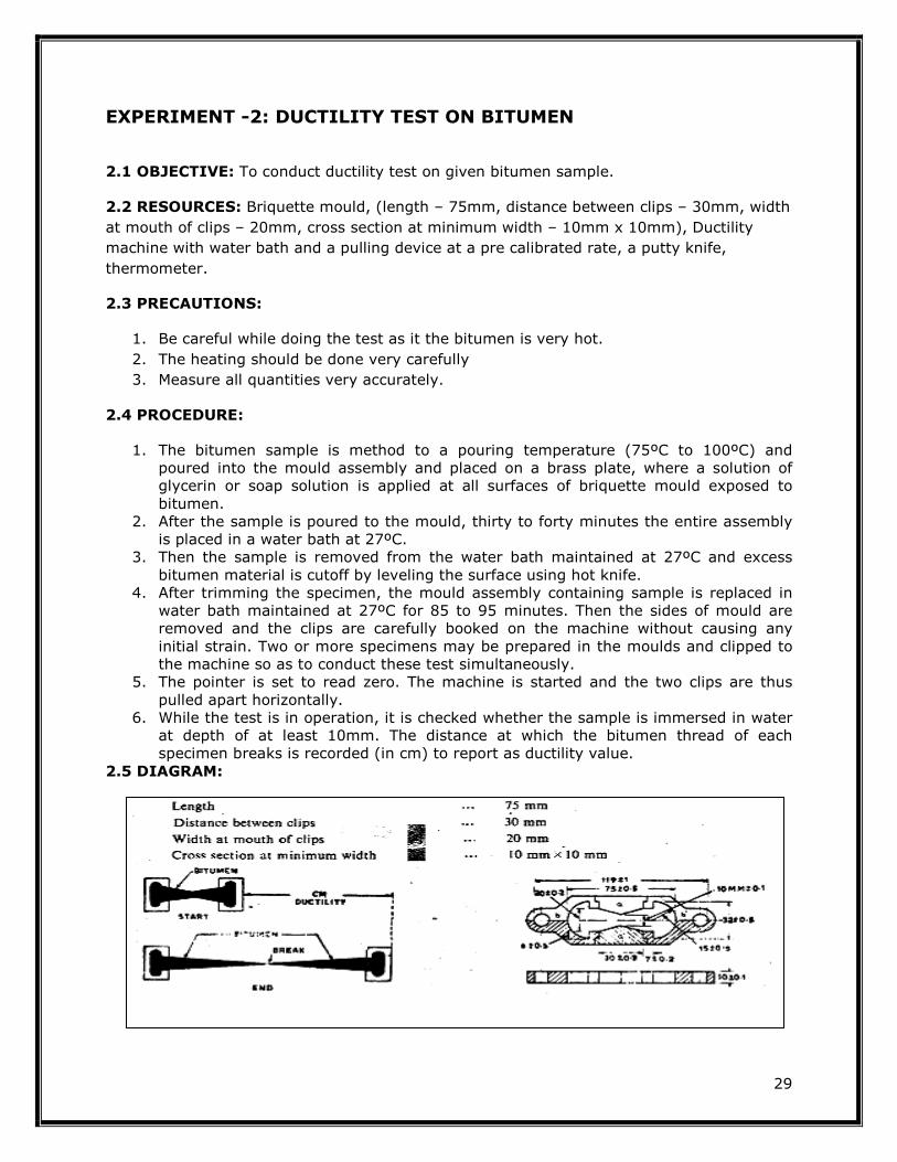
EXPERIMENT -2: DUCTILITY TEST ON BITUMEN
2.1 OBJECTIVE: To conduct ductility test on given bitumen sample.
2.2 RESOURCES: Briquette mould, (length – 75mm, distance between clips – 30mm, width
at mouth of clips – 20mm, cross section at minimum width – 10mm x 10mm), Ductility
machine with water bath and a pulling device at a pre calibrated rate, a putty knife,
thermometer.
2.3 PRECAUTIONS:
1. Be careful while doing the test as it the bitumen is very hot.
2. The heating should be done very carefully
3. Measure all quantities very accurately.
2.4 PROCEDURE:
1. The bitumen sample is method to a pouring temperature (75ºC to 100ºC) and poured into the mould assembly and placed on a brass plate, where a solution of glycerin or soap solution is applied at all surfaces of briquette mould exposed to bitumen.
2. After the sample is poured to the mould, thirty to forty minutes the entire assembly is placed in a water bath at 27ºC.
3. Then the sample is removed from the water bath maintained at 27ºC and excess bitumen material is cutoff by leveling the surface using hot knife.
4. After trimming the specimen, the mould assembly containing sample is replaced in water bath maintained at 27ºC for 85 to 95 minutes. Then the sides of mould are removed and the clips are carefully booked on the machine without causing any initial strain. Two or more specimens may be prepared in the moulds and clipped to the machine so as to conduct these test simultaneously.
5. The pointer is set to read zero. The machine is started and the two clips are thus pulled apart horizontally.
6. While the test is in operation, it is checked whether the sample is immersed in water at depth of at least 10mm. The distance at which the bitumen thread of each specimen breaks is recorded (in cm) to report as ductility value.
2.5 DIAGRAM:

30
2.6 TABLE AND CALCULATION:
2.7 RESULT:
The ductility value of the given bitumen sample is _________________ cm.
2.8 PRE LAB QUESTIONS:
1. List the factors that affect the result of a ductility test. 2.9 LAB ASSIGNMENT:
How do you determine the ductility of the bitumen?
2.10 POST LAB QUESTIONS:
1. What do you understand by the term repeatability and reproducibility? 2. Explain the significance of ductility test.

31
EXPERIMENT -3: SOFTENING POINT OF BITUMEN
3.1 OBJECTIVE: To determine the softening point of given paving bitumen as per IS:
1205.
3.2 RESOURCES: Ring and Ball apparatus, Water bath with stirrer, Thermometer,
Glycerin, etc. Steel balls each of 9.5mm and weight of 2.5±0.08gm.
3.3 PRECAUTIONS:
1. Be careful while doing the test as it the bitumen is very hot.
2. The heating should be done very carefully
3. Measure all quantities very accurately.
3.4 PROCEDURE:
1. Sample material is heated to a temperature between 75º and 100ºC above the approximate softening point until it is completely fluid and is poured in heated rings placed on the metal plate.
2. To avoid sticking of the bitumen to metal plate, coating is done to this with a solution of glycerin and dextrin.
3. After cooling the rings in air for 30 minutes, the excess bitumen is trimmed and rings are placed in the support.
4. At this time the temperature of distilled water is kept at 5ºC. This temperature is maintained for 15 minutes after which the balls are placed in position.
5. Then the temperature of water is raised at uniform rate of 5ºC per minute with a controlled heating unit, until the bitumen softens and touches the bottom plate by sinking of balls. At least two observations are made. For material whose softening point is above 80ºC, glycerin is used for heating medium and the starting temperature is 35ºC instead of 5ºC.
6. The temperature at the instant when each of the ball and sample touches the bottom plate of support is recorded as softening point value.
3.5 DIAGRAM:
Softening Test Concept

32
3.6 TABLE AND CALCULATION:
3.7 RESULT:
The softening point value of given bitumen sample is ___________________0C and grade of bitumen is ______________.
3.8 PRE LAB QUESTIONS:
1. What are the factors which affect the ring and ball test results?
3.9 LAB ASSIGNMENT:
How do you determine the softening point of the bitumen?
3.10 POST LAB QUESTIONS:
1. What is softening point? 2. If material A has softening point of 56 and B has 42 which binder is good and why?

33
EXPERIMENT – 4: FLASH AND FIRE POINT TESTS ON BITUMEN
4.1 OBJECTIVE: To determine the flash and fire point of a given bituminous material.
4.2 RESOURCES: Pensky -Martens closed cup tester, thermometer, heating source, flame
exposure.
4.3 PRECAUTIONS:
1. Be careful while doing the test as it the bitumen is very hot.
2. The heating should be done very carefully
3. Measure all quantities very accurately.
4.4 PROCEDURE:
1. All parts of the cup are cleaned and dried thoroughly before the test is started. 2. The material is filled in the cup up to a mark. The lid is placed to close the cup in a
closed system. All accessories including thermometer of the specified range are suitably fixed.
3. The bitumen sample is then heated. The test flame is lit and adjusted in such a way that the size of a bed is of 4mm diameter. The heating of sample is done at a rate of 5º to 6ºC per minute. During heating the sample the stirring is done at a rate of approximately 60 revolutions per minute.
4. The test flame is applied at intervals depending upon the expected flash and fire points and corresponding temperatures at which the material shows the sign of flash and fire are noted.
4.5 DIAGRAM:
Flash and Fire Point Test Concept

34
4.6 TABLE AND CALCULATION:
4.7 RESULT:
The temperature at which the flame application that causes a bright flash (Flash Point) ______________0C and temperature at which the sample catches fire (Fire Point) ______________0C.
4.8 PRE LAB QUESTIONS:
1. Define flash and fire points.
4.9 LAB ASSIGNMENT:
How do you determine the flash and fire points of the bitumen?
4.10 POST LAB QUESTIONS:
1. What is the significance of flash and fire point test? 2. What are the parameter that affects the result of flash and fire point tests?

35
III. TESTS ON CEMENT AND CONCRETE

36
EXPERIMENT NO -1: NORMAL CONSISTENCY OF CEMENT
1.1 OBJECTIVE: To determine the normal consistency of a given sample of cement.
1.2 RESOURCES: Vicat apparatus conforming to IS: 5513-1976, Balance, Gauging Trowel,
Stop Watch, etc.
1.3 PRECAUTIONS
1. The cement balls any should be powdered before of adding water to the cement
2. While preparing the test block do not press the cement in the mould.
3. Release the needles gently.
4. The experiment should be performed away from vibrations and other disturbances.
1.4 DIAGRAM
1.5 PROCEDURE
1. The standard consistency of a cement paste is defined as that consistency which
will permit the Vicat plunger to penetrate to a point 5 to 7 mm from the bottom
of the Vicat mould 2. Initially a cement sample of about 300 g is taken in a tray and is mixed with a
known percentage of water by weight of cement, say starting from 26% and
then it is increased by every 2% until the normal consistency is achieved. 3. Prepare a paste of 300 g of Cement with a weighed quantity of potable or
distilled water, taking care that the time of gauging is not less than 3 minutes,
not more than 5 min, and the gauging shall be completed before any sign of
setting occurs. The gauging time shall be counted from the time of adding water
to the dry cement until commencing to fill the mould.

37
4. Fill the Vicat mould (E) with this paste, the mould resting upon a non-porous
plate. After completely filling the mould, smoothen the surface of the paste,
making it level with the top of the mould. The mould may be slightly shaken to
expel the air. 5. Place the test block in the mould, together with the non-porous resting plate,
under the rod bearing the plunger; lower the plunger gently to touch the surface
of the test block, and quickly release, allowing it to sink into the paste. This
operation shall be carried out immediately after filling the mould.
6. Prepare trial pastes with varying percentages of water and test as described
above until the amount of water necessary for making up the standard
consistency as defined in Step 1 is found
1.6 TABLE AND CALCULATION
Express the amount of water as a percentage by mass of the dry cement to the first place of decimal.
Weight of cement
Percentage by water of dry Cement (%)
Amount of water added
(ml)
Penetration
(mm)
Sr. No.
(gm)
1
2
3
4
1.7 RESULT
The normal consistency of a given sample of cement is _ _ _ _ _ _ %
1.8 PRE LAB QUESTIONS
1. What do you understand by standard consistency
2. What is the weight of the moving part of the vicat apparatus and what are the
dimensions of the plunger
1.9 LAB ASSIGNMENT
How do you perform the normal consistency test for cement?
1.10 POST LAB QUESTIONS
1. What is importance of the test?
2. What precautions do you observe in performing the above tests

38
EXPERIMENT - 2: DETERMINATION OF SETTING TIMES OF
STANDARD CEMENT PASTE
2.1 OBJECTIVE: To determine the initial and final setting time of a given sample of
cement
2.2 RESOURCES: Vicat apparatus conforming to IS: 5513-1976, Balance, Gauging Trowel,
Stop Watch, etc
2.3 PRECAUTIONS
1. The cement balls any should be powdered before of adding water to the cement
2. While preparing the test block do not press the cement in the mould.
3. Release the needles gently.
4. The experiment should be performed away from vibrations and other disturbances.
2.4 PROCEDURE
1. Preparation of Test Block - Prepare a neat 300 gm cement paste by
gauging the cement with 0.85 times the water required to give a paste of
standard consistency. Potable or distilled water shall be used in preparing the
paste.
2. Start a stop-watch at the instant when water is added to the cement. Fill the
Vicat mould with a cement paste gauged as above, the mould resting on a
nonporous plate. Fill the mould completely and smooth off the surface of the
paste making it level with the top of the mould.
3. Immediately after moulding, place the test block in the moist closet or moist
room and allow it to remain there except when determinations of time of
setting are being made.
4. Determination of Initial Setting Time - Place the test block confined in the
mould and resting on the non-porous plate, under the rod bearing the needle
( C ); lower the needle gently until it comes in contact with the surface of the
test block and quickly release, allowing it to penetrate into the test block
5. Repeat this procedure until the needle, when brought in contact with the test
block and released as described above, fails to pierce the block beyond 5.0 ±
0.5 mm measured from the bottom of the mould shall be the initial setting
time.
6. Determination of Final Setting Time - Replace the needle (C) of the Vicat
apparatus by the needle with an annular attachment (F).
7. The cement shall be considered as finally set when, upon applying the needle
gently to the surface of the test block, the needle makes an impression
thereon, while the attachment fails to do so.
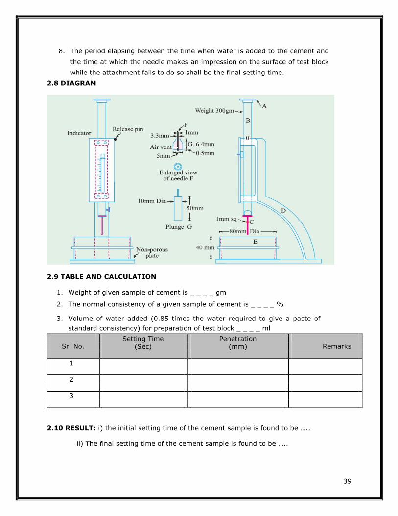
39
8. The period elapsing between the time when water is added to the cement and
the time at which the needle makes an impression on the surface of test block
while the attachment fails to do so shall be the final setting time.
2.8 DIAGRAM
2.9 TABLE AND CALCULATION
1. Weight of given sample of cement is _ _ _ _ gm
2. The normal consistency of a given sample of cement is _ _ _ _ %
3. Volume of water added (0.85 times the water required to give a paste of
standard consistency) for preparation of test block _ _ _ _ ml
Sr. No.
Setting Time (Sec)
Penetration (mm)
Remarks
1
2
3
2.10 RESULT: i) the initial setting time of the cement sample is found to be …..
ii) The final setting time of the cement sample is found to be …..

40
2.11 PRE LAB QUESTIONS
1. What do you understand by initial and final setting times of a cement sample
2. What is importance of the test?
3. What precautions do you observe in performing the above tests
4. What is the weight of the moving part of the Vicat apparatus and what are the
dimensions of the setting time needle
2.12 LAB ASSIGNMENT
How do you determine the initial and final setting times for cement?
2.13 POST LAB QUESTIONS
1. What are is specifications for setting times of various types of cements
recommended for us e on a construction site
2. What is the amount of water to be added for initial setting time?
3. What is difference between setting and hardening

41
EXPERIMENT NO-3 (a): DETERMINATION OF SPECIFIC GRAVITY OF
CEMENT
3(a).1 OBJECTIVE: To determine specific gravity of a cement sample by density bottle
method.
3(a).2 RESOURCES: Specific gravity bottle, kerosene free from water, weighing balance,
Constant temperature water bath
3(a).3 PRECAUTIONS
1. While pouring cement in the specific gravity bottle care should be taken to avoid
splashing and cement should not adhere to the inside of the flask above the liquid.
2. The kerosene or Naphtha should be completely free from water.
3. The specific gravity bottle should be kept in a constant temperature water bath
sufficiently long to ensure same temperature before each weighing is made.
4. All air bubbles shall be eliminated in filling the apparatus and inserting the stopper.
5. Duplicate results of specific gravity should agree within 0. 01.
3(a).4 PROCEDURE
1. Clean and dry the specific gravity bottle and weigh it with the stopper
(W1).
2. Fill the bottle with distilled water and measure the weight of the bottle
along with stopper (W2)
3. Dry the specific gravity bottle and fill it with kerosene and measure the
weight along with stopper(W3)
4. Pour some of the kerosene out and introduce a weighed quantity of
cement (which would be measured prior to the introduction) into the
bottle. Roll the bottle gently in the inclined position until no further air
bubble rise to the surface. Let the weight of the cement is W5.
5. Fill the bottle to the top with kerosene and measure the weight of bottle
along with stopper (W4)
6. All the above weighing should be done at the room temperature of 27 °C
± 1 °C.

42
3(a).5 DIAGRAM
3(a).6 TABLE AND CALCULATION
S.No. Description of item Trail 1 Trail 2 Trail 3
1 Weight of empty dry bottle (W1) gms
2 Weight of bottle + water (W2) gms
3 Weight of bottle + Kerosene (W3), gms
4 Weight of bottle + Cement + Kerosene (W4) gms
5 Weight of cement (W5) gms
Specific gravity of kerosene (g) = ((W-W1)/ (W2-W1)).
Specific gravity of cement (G) = ((W2(W3-W1))/ (W3-W4)(W2-W1)).
3(a).7 RESULT:
The Specific gravity of the cement sample is ……………….
3(a).8 PRE LAB QUESTIONS
1. Differentiate between density and specific gravity of a material.
2. State the importance of this test.
3. Name other methods that can be used for finding the specific gravity of cement

43
3(a).9 LAB ASSIGNMENT
How do you determine the Specific gravity for cement?
3(a).10 POST LAB QUESTIONS
1. What is the effect on the specific gravity value if the air bubbles are not removed
completely?
2. Why constant temperature bath is used in this experiments.
3. Why do we use kerosene or naphtha in this experiment?"

44
EXPERIMENT NO-3 (b): DETERMINATION OF SOUNDNESS OF
CEMENT BY LE-CHATELIER METHOD
3(b).1 OBJECTIVE: To determine the soundness of a given sample of cement by Le-
Chatlier method.
3(b).2 RESOURCES: Le- Chatlier test apparatus conform to IS: 5514-1969, Balance,
Gauging Trowel, Water Bath etc.
3(b).3 PRECAUTIONS
1. Oil the mould with a thin layer of mineral oil
2. Lengths L1 and L2 should be measured accurately
3. The temperature of autoclave should be raised and lowered gradually
4. The experiment should be performed away from vibrations and other
disturbances.
3(b).4 PROCEDURE
1. place the lightly oiled mould on a lightly oiled glass sheet and fill it with
cement paste formed by gauging cement with 0.78 times the water
required to give a paste of standard consistency
2. The paste shall be gauged in the manner and under the conditions
prescribed in experiment No.1, taking care to keep the edges of the mould
gently together while this operation is being performed.
3. Cover the mould with another piece of lightly oiled glass sheet, place a
small weight on this covering glass sheet and immediately submerge the
whole assembly in water at a temperature of 27 ± 2°C and keep there for
24 hours.
4. Measure the distance separating the indicator points to the nearest 0.5
mm. Submerge the mould again in water at the temperature prescribed
above.
5. Bring the water to boiling, with the mould kept submerged, in 25 to 30
minutes, and keep it boiling for three hours. Remove the mould from the
water, allow it to cool and measure the distance between the indicator
points.
6. The difference between these two measurements indicates the expansion
of the cement. This must not exceed 10 mm for ordinary, rapid hardening
and low heat Portland cements. If in case the expansion is more than 10
mm as tested above, the cement is said to be unsound.

45
3(b).5 DIAGRAM
3(b).6 TABLE AND CALCULATION
Express the amount of water as a percentage by mass of the dry cement to the first place of
decimal.
Sr. No.
Distance separating the indicator
submerge in normal temp water for 24
hours
Distances separating the
indicator submerge in boiling for three
hours
The difference between these two measurements
Remarks
1
2
3
4
3(b).7 RESULT:
The given cement is said to be sound / unsound.
3(b).8 PRE LAB QUESTIONS
1. What does it mean of soundness of the cement
2. What is diameter of lechateliers apparatus
3. What is meant by unsoundness and how it is caused
4. What is importance of the soundness of the cement
5. What precautions does a manufacturer to take to prevent unsound cement

46
3(b).9 LAB ASSIGNMENT
How do you determine the soundness for cement?
3(b).10 POST LAB QUESTIONS
1. Distinguish between expansion and shrinkage of the cement paste
2. What is maximum expansion for ordinary Portland cement
3. What is the cause of free lime in cement
4. What is the necessity to keep the cement paste moist in this test while it is
setting
47
EXPERIMENT - 4: DETERMINATION OF COMPRESSIVE STRENGTH OF
CEMENT
4.1 OBJECTIVE: To determine the compressive strength of a given sample of cement.
4.2 RESOURCES: The standard sand to be used in the test shall conform to IS : 650-1966,
Vibration Machine, Poking Rod, Cube Mould of 70.6 mm size conforming to IS : 10080-
1982, Balance, Gauging Trowel, Stop Watch, Graduated Glass Cylinders, etc.
4.3 PRECAUTIONS
1. The moulds should be oiled before the experiment
2. The weighing should be done accurately
3. The temperature and humidity must be accurately controlled
4. Increase the load gradually during testing
4.4 PROCEDURE
1. Preparation of test specimens - Clean appliances shall be used for mixing
and the temperature of water and that of the test room at the time when
the above operations are being performed shall be 27 ± 2°C.
Potable/distilled water shall be used in preparing the cubes.
2. The material for each cube shall be mixed separately and the quantity of
cement, standard sand and water shall be as follows: Cement 200g and
standard Sand 600g are required to produce a paste of standard
consistency determined as described in IS : 4031 (Part 4)-1988 or
Experiment No.1(a)
3. Place on a nonporous plate, a mixture of cement and standard sand. Mix it
dry with a trowel for one minute and then with water until the mixture is
of uniform colour. The quantity of water to be used shall be as specified in
step 2. The time of mixing shall in any event be not less than 3 min and
should the time taken to obtain a uniform colour exceed 4 min, the
mixture shall be rejected and the operation repeated with a fresh quantity
of cement, sand and water.
4. Moulding Specimens - In assembling the moulds ready for use, treat the
interior faces of the mould with a thin coating of mould oil.
5. Place the assembled mould on the table of the vibration machine and hold
it firmly in position by means of a suitable clamp. Attach a hopper of
suitable size and shape securely at the top of the mould to facilitate filling
and this hopper shall not be removed until the completion of the vibration
period.

48
6. Immediately after mixing the mortar in accordance with step 1 & 2 Place
the mortar in the cube mould and prod with the rod. Place the mortar in
the hopper of the cube mould and prod again as specified for the first
layer and then compact the mortar by vibration.
7. The period of vibration shall be two minutes at the specified speed of 12
000 ± 400 vibration per minute.
8. At the end of vibration, remove the mould together with the base plate
from the machine and finish the top surface of the cube in the mould by
smoothing the surface with the blade of a trowel.
9. Curing Specimens - keep the filled moulds in moist closet or moist room
for 24 ± 1 hour after completion of vibration. At the end of that period,
remove them from the moulds and immediately submerge in clean fresh
water and keep there until taken out just prior to breaking.
10. The water in which the cubes are submerged shall be renewed every 7
days and shall be maintained at a temperature of 27 ± 2°C. After they
have been taken out and until they are broken, the cubes shall not be
allowed to become dry.
11. Test three cubes for compressive strength for each period of curing
mentioned under the relevant specifications (i.e. 3 days, 7 days, 28 days)
12. The cubes shall be tested on their sides without any packing between the
cube and the steel plattens of the testing machine. One of the plattens
shall be carried on a base and shall be self-adjusting, and the load shall be
steadily and uniformly applied, starting from zero at a rate of 35
N/mm2/min.
4.5 DIAGRAM

49
4.6 TABLE AND CALCULATION
Age of
Weight of Cross- Compressive Average Sr.
No. Cement
Cube
Sectional Load
(N)
strength
Compressive
Cube
(gm)
area (mm2)
(N/mm2) strength
(MPa)
1
2 7 Days
3
4
5 28 Days `
6
4.7 CALCULATIONS: The measured compressive strength of the cubes shall be calculated by dividing the
maximum load applied to the cubes during the test by the cross-sectional area,
calculated from the mean dimensions of the section and shall be expressed to the
nearest 0.5 N/mm2. In determining the compressive strength, do not consider
specimens that are manifestly faulty, or that give strengths differing by more than
10 percent from the average value of all the test specimens.
4.8 RESULT
i) The average 3 Days Compressive Strength of given cement sample is found to be …..….. ii) The average 7 Days Compressive Strength of given cement sample is found to be …..…..
iii) The average 28 Days Compressive Strength of given cement sample is found to be
…..…..

50
4.9 PRE LAB QUESTIONS
1. What is the percentage of water required for preparing 1:3 cement sand mortar for
compressive strength test
2. What is significance of the test
3. What are IS specifications for compressive strength of 1:3 cement sand mortar after 3
days and 7 days
4. What is the minimum number of specimens to be made or each age of testing
4.10 LAB ASSIGNMENT
How do you determine the compressive strength of cement?
4.11 POST LAB QUESTIONS
1. How is the curing of a test specimen done
2. Why should not the specimen be allowed to dry until they are tested
3. What is the rate of loading
4. How can you be sure that the cement and sand are thoroughly mixed

51
EXPERIMENT – 5 (a): DETERMINATION WORKABILITY OF FRESH
CONCRETE BY COMPACTING FACTOR TEST
5 (a).1 OBJECTIVE: To determine the relative consistency of freshly mixed concrete by
the use of Compacting Factor Test
5 (a).2 RESOURCES : Compacting Factor Apparatus, Trowel, Scoop about 150 mm long.,
Balance capable of weighing up to 25 kg with the sensibility of 10 g. Weights and weighing
device, Tamper ( 16 mm in diameter and 600 mm length), Ruler, Tools and containers for
mixing, or concrete mixer etc.
5 (a).3 PRECAUTIONS:
1. Oil the inner surface of apparatus before starting of the experiment
2. Fill the top hopper gently and to the same extent each time
3. The hoppers and cylinder must be washed, cleaned and wiped before use.
4. The experiment should be performed away from vibrations and on level ground.
5 (a).4 PROCEDURE:
1. The internal surface of the hoppers and cylinder shall be thoroughly clean and
free from superfluous moisture and any set of concrete commencing the test.
2. The sample of concrete to be tested shall be placed gently in the upper hopper
using the scoop. The trap door shall be opened immediately after filling or
approximately 6 min after water is added so that the concrete fails into the
lower hopper. During this process the cylinder shall be covered.
3. The lower hopper opened and the concrete allowed falling to into the cylinder.
4. For some mixes have a tendency to stick in one or both of the hoppers. If this
occurs the concrete shall be helped through by pushing the tamping rod
gently into the concrete from the top.
5. The excess of concrete remaining above the level of the top of the cylinder
shall then be cut off by holding a trowel in each hand, with the plane of the
blades horizontal, and moving them simultaneously one from each side across
the top of the cylinder, at the same time keeping them pressed on the top
edge of the cylinder. The outside of the cylinder shall then be wiped clean.
This entire process shall be carried out at a place free from vibration or shock.
6. Determine the weight of concrete to the nearest 10 g. This is known as "weight of partially compacted concrete", Wp.
7. Refill the cylinder with concrete from the same sample in layers approximately
50 mm depth. The layers being heavily rammed with the compacting rod or
vibrated to obtain full compaction. The top surface of the fully compacted
concrete shall be carefully struck off and finished level with the top of the

52
cylinder. Clean up the outside of the cylinder.
8. Determine the weight of concrete to the nearest 10 g. This is known as
"weight of fully compacted concrete", Wf.
The compacting factor, CF can be calculated as follows:
The compaction factor = weight of partially compacted concrete/weight of fully
compacted concrete.
5 (a).5 DIAGRAM:

53
5 (a).6 TABLE AND CALCULATION:
The compacting factor is defined as the ratio of the weight of partially compacted
concrete to the weight of fully compacted concrete. It shall normally be stated to
the nearest second decimal place.
Sr. Description
Sample 1
Sample 2
No
1. Weight of Empty Cylinder (W1)
2. Weight of Cylinder + Free Fall Concrete (W2)
3. Weight of Cylinder + Hand Compacted Concrete (W2)
4. Weight of Partially Compacted Concrete (Wp=W2-W1)
5. Weight of Fully Compacted Concrete (Wf=W2-W1)
6 The Compacting Factor =Wp/Wf
5 (a).7 RESULT:
The Compaction factor of the concrete is _ _ _ _ _.
5 (a).8 PRE LAB QUESTIONS:
1. Define the compaction factor
2. How do you compare slump test with compaction factor test
3. Will workability increase or decrease with increase in compaction factor and why
5 (a).9 LAB ASSIGNMENT
How do you determine the compaction factor of the concrete?
5 (a).10 POST LAB QUESTIONS:
1. Does the compaction factor test gives a better measure of workability than slump test
2. Differentiate between workability and consistency
3. Can we use this test in the field also
4. Write a note on importance of compaction factor in concrete mix design.

54
EXPERIMENT -5 (b): DETERMINATION WORKABILITY OF FRESH
CONCRETE BY SLUMP CONE TEST
5 (b).1 OBJECTIVE: To determine the relative consistency of freshly mixed concrete by
the use of Slump Test.
5 (b).2 RESOURCES: The Slump Cone apparatus for conducting the slump test essentially
consists of a metallic mould in the form of a frustum of a cone having the internal
dimensions as under: Bottom diameter: 20 cm, Top diameter: 10 cm, Height: 30 cm and
the thickness of the metallic sheet for the mould should not be thinner than 1.6 mm
Weights and weighing device, Tamper ( 16 mm in diameter and 600 mm length), Ruler,
Tools and containers for mixing, or concrete mixer etc.
5 (b).3 PRECAUTIONS:
1. Apply the strokes with the tamping rod uniformly through the full depth.
2. Remove the mould very slowly by lifting it upwards so that concrete does not get
disturbed
3. Test should be completed in a minimum of 2 to 3 minutes.
4. The experiment should be performed away from vibrations and other disturbances.
5 (b).4 PROCEDURE:
1. Dampen the mould and place it on a flat, moist, nonabsorbent (rigid) surface.
It shall be held firmly in place during filling by the operator standing on the
two foot pieces. Immediately fill the mold in three layers, each approximately
one third the volume of the mold.
2. Rod each layer with 25 strokes of the tamping rod. Uniformly distribute the
strokes over the cross section of each layer.
3. In filling and rodding the top layer, heap the concrete above the mold before
rodding start. If the rodding operation results in subsidence of the concrete
below the top edge of the mold, add additional concrete to keep an excess of
concrete above the top of the mold at all time.
4. After the top layer has been rodded, strike off the surface of the concrete by
means of trowel and rolling motion of the tamping rod.
5. Remove the mold immediately from the concrete by raising it carefully in the
vertical direction. Raise the mold a distance of 300 mm in 5 ± 2 sec by a
steady upward lift with no lateral or torsional motion.
6. Immediately measure the slump by determining the vertical difference
between top of the mould and the displaces original center of the top surface
of the specimen. Complete the entire test from the start of the filling through
removal of the mold without interruption and complete it within 2½ min.
7. If a decided falling away or shearing off of concrete from one side or portion

55
of the mass occurs, disregard the test and make a new test on another
portion of the sample. If two consecutive tests on a sample of concrete show
a falling away or shearing off of a portion of concrete from the mass of
specimen, the concrete lacks necessary plasticity and cohesiveness for the
slump test to be applicable.
8. After completion of the test, the sample may be used for casting of the
specimens for the future testing.
5 (b).5 DIAGRAM
The pattern of slump is shown True Slump/Shear Slump/ Collapse Slump
5 (b).6 TABLE AND CALCULATION:
Sr. No. W/C ratio Slump (mm)
1
2
3
4
5 (b).7 RESULT:
The slump of concrete ……….. MM indicate Low/ Medium/ High Degree of workability

56
5 (b).8 PRE LAB QUESTIONS
1. Define the slump of concrete
2. State the significance of slump test
3. State the slump for concrete used for 1.roads, columns, mass concrete in foundation
5 (b).9 LAB ASSIGNMENT
How do you determine the slump of the concrete?
5 (b).10 POST LAB QUESTIONS
1. Differentiate by sketches the terms of true slump, shear and collapse type of slumps
2. Define the workability and consistency of freshly mixed concrete
3. How does W/C ratio effects the workability

57
EXPERIMENT – 5 (c): DETERMINATION OF CONSISTENCY OF
CONCRETE BY VEE-BEE CONSISTOMETER METHOD
5 (c).1OBJECTIVE: The determination of consistency of concrete using a Vee-Bee
Consistometer, which determines the time required for transforming, by vibration, a
concrete specimen in the shape of a conical frustum into a cylinder.
5 (c).2 RESOURCES: Vee Bee Consistometer: a) A vibrator table resting upon elastic
supports, b) A metal pot, c) A sheet metal cone, open at both ends, and d) A standard iron
rod. Weights and weighing device, Tamper ( 16 mm in diameter and 600 mm length), Ruler,
Tools and containers for mixing, or concrete mixer etc.
5 (c).3 PRECAUTIONS:
1. The slump test to be performed before giving vibrations as per the standard
specifications
2. The experiment should be performed away from vibrations and other disturbances.
3. The moulds should be oiled before the starting of the experiment.
5 (c).4 DIAGRAM:
5 (c).5 PROCEDURE:
1. Slump test as described earlier is performed, placing the slump cone inside the
sheet metal cylindrical pot of the Consistometer. 2. The glass disc attached to the swivel arm is turned and placed on the top of the
concrete in the pot. The electrical vibrator is then switched on and
simultaneously a stop watch started.
58
3. The vibration is continued till such a time as the conical shape of the concrete
disappears and the concrete assumes a cylindrical shape. This can be judged by
observing the glass disc from the top for disappearance of transparency. 4. Immediately when the concrete fully assumes a cylindrical shape, the stop
watch is switched off. The time required for the shape of concrete to change
from slump cone shape to cylindrical shape in seconds is known as Vee Bee
Degree. 5. This method is very suitable for very dry concrete whose slump value cannot be
measured by Slump Test, but the vibration is too vigorous for concrete with a
slump greater than about 50 mm.
5 (c).6 TABLE AND CALCULATION:
Sr. No. W/C ratio Vee Bee degree (Sec)
1
2
3
4
5 (c).7 RESULT
The Vee Bee Degree of concrete ……….. Sec
Indicate Low/ Medium/ High Degree of workability
5 (c).8 PRE LAB QUESTIONS
1. How do you measure the workability of the mix in this test
2. Why the name Vee bee has been given to this test
5 (c).9 LAB ASSIGNMENT
How do you determine the compaction factor of the concrete?
5 (c).10 POST LAB QUESTIONS
1. This test is a development of the remoulding test explain
2. State the number of Vee bee degrees for the following types of mixes 1. Very dry 2. Dry
3. Semi fluid .4 fluid

59
EXPERIMENT- 6: DETERMINE COMPRESSIVE STRENGTH OF CUBIC
CONCRETE SPECIMENS
6.1 OBJECTIVE: The test method covers determination of compressive strength of cubic
concrete specimens. It consists of applying a compressive axial load to molded cubes at a
rate which is within a prescribed range until failure occurs.
6.2 RESOURCES:
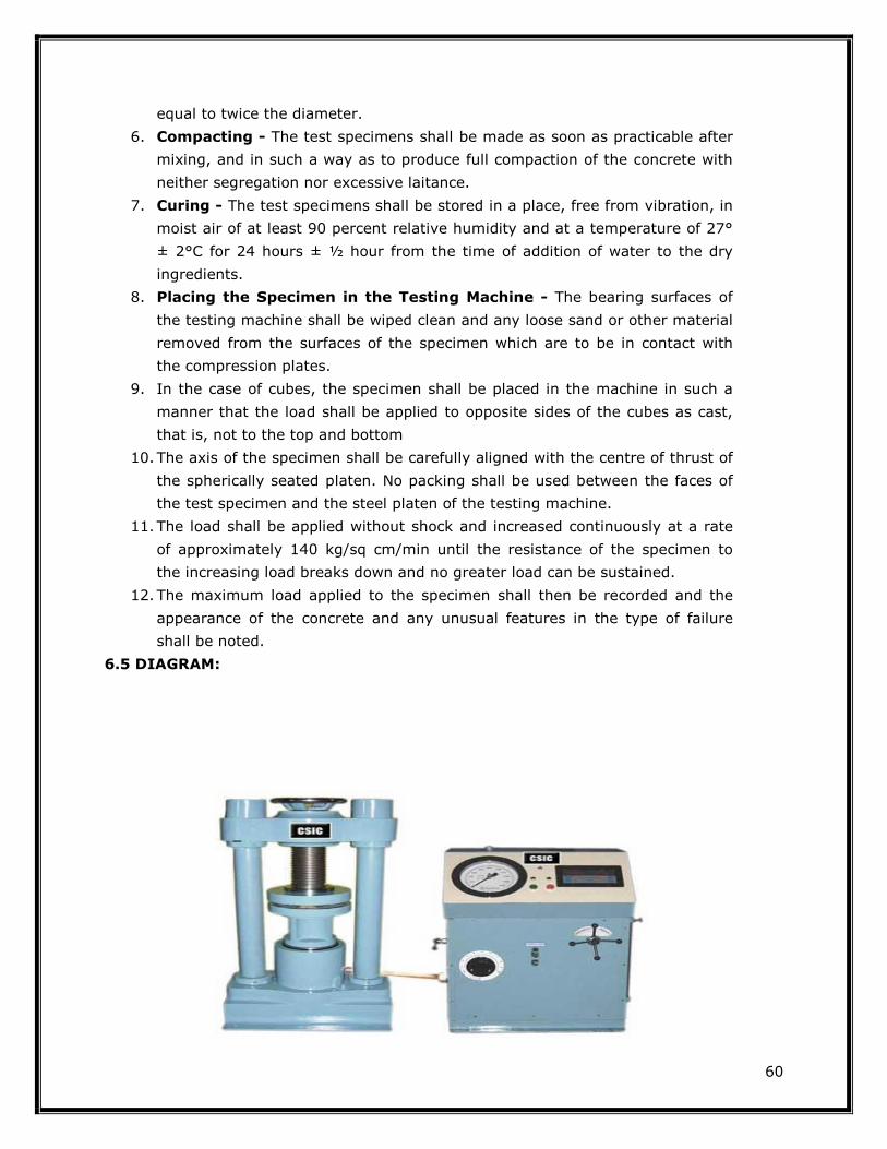
Testing Machine - The testing machine may be of any reliable type, of sufficient
capacity for the tests and capable of applying the load at the rate specified in 5.5.
The permissible error shall be not greater than ± 2 percent of the maximum load. Cube Moulds - The mould shall be of 150 mm size conforming to IS: 10086-1982. Cylinders -The cylindrical mould shall be of 150 mm diameter and 300 mm height
conforming to IS: 10086-1982. Weights and weighing device, Tools and containers for mixing, Tamper (square in cross section) etc. 6.3 PRECAUTIONS:
1. All the materials should be weighed to an accuracy of 1 in 1000.
2. The mould and base plate should be oiled lightly
3. Cubes should be placed in the testing machine centrally on platens
4. The cubes should not be allowed to dry and they must be tested wet.
6.4 PROCEDURE:
1. Sampling of Materials - Samples of aggregates for each batch of concrete
shall be of the desired grading and shall be in an air-dried condition. The
cement samples, on arrival at the laboratory, shall be thoroughly mixed dry
either by hand or in a suitable mixer in such a manner as to ensure the
greatest possible blending and uniformity in the material.
2. Proportioning - The proportions of the materials, including water, in
concrete mixes used for determining the suitability of the materials available,
shall be similar in all respects to those to be employed in the work.
3. Weighing - The quantities of cement, each size of aggregate, and water for
each batch shall be determined by weight, to an accuracy of 0.1 percent of
the total weight of the batch.
4. Mixing Concrete - The concrete shall be mixed by hand, or preferably, in a
laboratory batch mixer, in such a manner as to avoid loss of water or other
materials. Each batch of concrete shall be of such a size as to leave about 10
percent excess after moulding the desired number of test specimens.
5. Mould - Test specimens cubical in shape shall be 15 × 15 × 15 cm. If the
largest nominal size of the aggregate does not exceed 2 cm, 10 cm cubes
may be used as an alternative. Cylindrical test specimens shall have a length
60
equal to twice the diameter.
6. Compacting - The test specimens shall be made as soon as practicable after
mixing, and in such a way as to produce full compaction of the concrete with
neither segregation nor excessive laitance.
7. Curing - The test specimens shall be stored in a place, free from vibration, in
moist air of at least 90 percent relative humidity and at a temperature of 27°
± 2°C for 24 hours ± ½ hour from the time of addition of water to the dry
ingredients.
8. Placing the Specimen in the Testing Machine - The bearing surfaces of
the testing machine shall be wiped clean and any loose sand or other material
removed from the surfaces of the specimen which are to be in contact with
the compression plates.
9. In the case of cubes, the specimen shall be placed in the machine in such a
manner that the load shall be applied to opposite sides of the cubes as cast,
that is, not to the top and bottom
10. The axis of the specimen shall be carefully aligned with the centre of thrust of
the spherically seated platen. No packing shall be used between the faces of
the test specimen and the steel platen of the testing machine.
11. The load shall be applied without shock and increased continuously at a rate
of approximately 140 kg/sq cm/min until the resistance of the specimen to
the increasing load breaks down and no greater load can be sustained.
12. The maximum load applied to the specimen shall then be recorded and the
appearance of the concrete and any unusual features in the type of failure
shall be noted.
6.5 DIAGRAM:

61
6.6 TABLE AND CALCULATION:
Sr. No. Description Cube 1 Cube 2 Cube 3
1 Identification Mark
2 Date of casting
3 Date of testing
4 Age of specimen
5 Curing condition
6 Dimensions of specimen
7 Weight of specimen
8 Cross sectional area
9 Maximum load
10 Compressive strength
11 Type of fracture
6.7 RESULT:
The Compressive strength of the concrete is …………………….kN/sq.mm
6.8 PRE LAB QUESTIONS:
1. State the importance of the compressive strength test
2. What is the minimum number of test to be conducted for each batch
3. State the sequence of mixing the ingredients of concrete
4. Why moulds are oiled before use
5. State the methods of compacting the concrete in the cube and cylinder moulds
6.9 LAB ASSIGNMENT:
How do you determine the compressive strength of the concrete?
6.10 POST LAB QUESTIONS:
1. Why capping is necessary for cylindrical specimens
2. State the rate of applying of load on compression specimens
3. State the nature of compression failures observed by you during testing
4. The cubes should be tested on sides and not along the direction of casting comment on
this statement
5. State the relationship between cube strength and cylinder strength

62
EXPERIMENT – 7: DETERMINATION OF BULKING OF FINE
AGGREGATE
7.1 OBJECTIVE: To determine bulking of a given sample of fine aggregate.
7.2 RESOURCES: Measuring jar, tamping rod etc.
7.3 PRECAUTIONS
1. All the weighing should be done accurately
2. No sand should be lost while filling or emptying the pot
3. Mix the water in the sand uniformly.
7.4 PROCEDURE:
1. Put sufficient quantity of the sand loosely into a container. Level off the top of the sand and pushing
a steel rule vertically down through the sand at the middle to the bottom, measure the height. Suppose this is h1 cm.
2. Empty the sand out of the container into another container where none of it
will be lost. Half fill the first container with water. Put back about half the sand
and rod it with a steel rod, about 6 mm in diameter, so that its volume is
reduced to a minimum. Then add the remainder of the sand and rod it in the
same way.
3. The percentage of bulking of the sand due to moisture shall be calculated from
the formula: Percentage bulking = (h / h1) x 100.
7.5 TABLE AND CALCULATION
1. Height with sand only h1………………mm
2. Height of the sand and water (h)………………mm The percentage of bulking of the sand = (h/h1) x 100 = …………%
7.6 RESULT
Bulking of a given sample of fine aggregate is found to be ……. %
7.7 PRE LAB QUESTIONS
1. State the importance of the test
2. State the relative bulking tendencies of fine aggregate
3. Explain void content as it implies to fine aggregate
7.8 LAB ASSIGNMENT
How do you determine the bulking of the aggregate?

63
7.9 POST LAB QUESTIONS
1. How would you test sand for silt and organic matter
2. How bulking of fine aggregate is taken into account while designing a
concrete mix
3. What is the reason for bulking of sand

64
EXPERIMENT-8: NON DESTRUCTIVE TESTING ON CONCRETE BY
REBOUND HAMMER
8.1 OBJECTIVE:
To test the concrete specimens by the non destructive test method of rebound hammer
8.2 RESOURCES:
Universal Testing Machine, Balance, scale, Schmidt hammer etc.
8.3 PRECAUTIONS:
1. All the materials should be weighed to an accuracy of 1 in 1000.
2. The mould and base plate should be oiled lightly
3. Cubes should be placed in the universal testing machine centrally on platens
4. Hold the hammer very carefully as it is directly affects the rebound number thus
affecting the compressive strength
8.4 DIAGRAM:
Operation of the rebound hammer

65
8.5 PROCEDURE:
1. The specimen to be tested shall be kept and cured in such a way that the softening
and hardening of the surface due to leaching of calcium hydroxide corrosion is
avoided.
2. The specimen surface shall be cleaned of dust or any loose material
3. The specimen shall be held or fixed in such a way that is does not yield under the
impact of hammer
4. The plunger of the hammer shall always be kept perpendicular to the surface
5. About ten to twelve readings shall be taken and their average value is calculated to
get a representative index of hardness
6. All the readings which are to be compared shall be taken while keeping the hammer
in a specified inclination with the vertical, while the hammer pointing the same
direction always. For the same surface the readings taken vertically are likely to be
different from those taken by keeping the hammer in the horizontal position
8.6 OBSERVATION, TABLE AND CALCULATION:
1. Concrete Mix used : 2. Type of cement and aggregate used : 3. Curing Conditions : 4. Age of Concrete : 5. Whether wet or dry :
Sr. No. 1 2 3 4 5 6 7
Rebound Number
Compressive Strength
8.7 RESULT:
The Compressive strength of the concrete by Rebound Hammer is …………….kN./sq.mm
8.8 PRE LAB QUESTIONS:
1. What is the significance of the test
2. Compare the rebound hammer test with other non destructive tests
3. In which conditions non destructive tests are performed
8.9 LAB ASSIGNMENT:
How do you determine the compressive strength of the concrete by Rebound Hammer
test?

66
8.10 POST LAB QUESTIONS:
1. What are drawbacks of the non destructive tests
2. Are these tests quite reliable
3. What precautions should be taken for performing the rebound hammer test?

67
IV. TESTS BEYOND SYLLABUS COVERAGE

68
EXPERIMENT - 1: DETERMINATION OF STABILITY OF THE BITUMEN
USING MARSHAL STABILITY APPARATUS
1.1 OBJECTIVE: To determine the stability of bitumen mixing with cement and sand for
paving roads.
1.2 RESOURCES: The apparatus consists the following resources.
1. Specimen mould assembly comprising mould cylinders 10.16cm diameter by
7.5cm height, base plate and extension collars.
2. Specimen extractor for extracting the compacted specimen from the mould. A
suitable bar is required to transfer load from the extension collar to the upper
proving ring attachment while extracting the specimen.
3. Compaction hammer having a flat circular tamping face 4.5kg sliding weight
constructed to provide a free fall of 45 cm.
4. Compaction pedestal consisting of a 20×20×45 cm wooden block capped with
30×30×2.5 cm MS plate to hold the mould assembly in position during compaction.
Mould holder is provided consisting of spring tension device designed to hold
compaction mould in place on compaction pedestal.
5. Loading Machine
6. Flow meter consists of guide, sieve and gauge.
7. Oven or hot plate
8. Water bath
9. Thermometers of range up to 200oC with sensitivity of 2.5oC and
10. Miscellaneous equipments like containers, mixing and handling tools etc.
1.3 PRECAUTIONS:
1. Be careful while doing the test as it the bitumen is very hot.
2. The heating should be done very carefully
3. Measure all quantities to the accuracy of 1 in 1000.
1.4 PROCEDURE:
1. 1200 grams of aggregates blended in the desired proportions is measured and
heated in the oven to the mixing temperature.
2. Bitumen is added at the mixing temperature to produce viscosity of 170 ± 1
centi-stokes at various percentages.
3. The materials are mixed in a heated pan with heated mixing tools.
4. The mixture is returned to the oven and reheated to the compacting
temperature (to produce viscosity of 280±30 centi-stokes).
5. The mixture is then placed in a heated Marshall mould with a collar and base
and the mixture is spaded around the sides of the mould. A filter paper is
placed under the sample and on top of the sample.
6. The mould is placed in the Marshall compaction pedestal.
7. The material is compacted with 50 blows of the hammer (or as specified), and
the sample is inverted and compacted in the other face with same number of
blows.
8. After compaction, the mould is in
removed and the sample is extracted by pushing it out the extractor.
9. The sample is allowed to stand for the few hours to cool.
10. The mass of the sample in air and when submerged is used to measure the
density of specimen, so as to allow, calculation of the void properties.
11. Specimens are heated to 60 ±1oC either in a water bath for 30
in an oven for minimum of 2 hours.
12. The specimens are removed from the water bath or oven and place in lower
segment of the breaking head. The upper segment of the breaking head of
the specimen is placed in position and the complete assembly is placed in
position on the testing machine.
13. The flow meter is placed over one of the post and is adjusted to read zero.
14. Load is applied at a rate of 50 mm per minute until the maximum load
reading is obtained.
15. The maximum load reading in Newton is observed. At the same instant the
flow as recorded on the flow meter in units of mm was also noted.
1.5 DIAGRAM:
The mould is placed in the Marshall compaction pedestal.
The material is compacted with 50 blows of the hammer (or as specified), and
the sample is inverted and compacted in the other face with same number of
After compaction, the mould is inverted. With collar on the bottom, the base is
removed and the sample is extracted by pushing it out the extractor.
The sample is allowed to stand for the few hours to cool.
The mass of the sample in air and when submerged is used to measure the
specimen, so as to allow, calculation of the void properties.
Specimens are heated to 60 ±1oC either in a water bath for 30-40 minutes or
in an oven for minimum of 2 hours.
The specimens are removed from the water bath or oven and place in lower
f the breaking head. The upper segment of the breaking head of
the specimen is placed in position and the complete assembly is placed in
position on the testing machine.
The flow meter is placed over one of the post and is adjusted to read zero.
plied at a rate of 50 mm per minute until the maximum load
The maximum load reading in Newton is observed. At the same instant the
flow as recorded on the flow meter in units of mm was also noted.
69
The material is compacted with 50 blows of the hammer (or as specified), and
the sample is inverted and compacted in the other face with same number of
verted. With collar on the bottom, the base is
The mass of the sample in air and when submerged is used to measure the
specimen, so as to allow, calculation of the void properties.
40 minutes or
The specimens are removed from the water bath or oven and place in lower
f the breaking head. The upper segment of the breaking head of
the specimen is placed in position and the complete assembly is placed in
The flow meter is placed over one of the post and is adjusted to read zero.
plied at a rate of 50 mm per minute until the maximum load
The maximum load reading in Newton is observed. At the same instant the

70
1.6 TABLE AND CALCULATION:
Sample no Weight in air(g) Weight in
water(g) Specific gravity
1
2
3
Sample Softening point(0C)
1
2
1.7 RESULT:
The specific gravity of the bitumen is ……… 1.8 PRE LAB QUESTIONS:
1. Explain softening point of the bitumen how is this value expressed
2. Briefly explain the marshal stability apparatus working procedure
1.9 LAB ASSIGNMENT:
How do you determine the stability of the bitumen using Marshal stability apparatus?
1.10 POST LAB QUESTIONS:
1. What are applications of softening point and marshal stability values
2. What are the recommenced maximum values for road pavement as per IS Code?