development status of kstar lhcd system - welcome...
TRANSCRIPT

Development Status ofDevelopment Status ofKSTAR LHCD SystemKSTAR LHCD System
September 24, 2004September 24, 2004
Y. S. Y. S. BaeBae, M. H. Cho, W. Namkung, M. H. Cho, W. Namkung
Plasma Sheath LabPlasma Sheath Lab..Department of Physics, Department of Physics, PohangPohang University of Science and TechnologyUniversity of Science and Technology
Development Status of KSTAR ECH and LHCD System (September, 2004) 2
LHCD system overview
Objectives• Required for the the steady-state operation of KSTAR.• Non-inductive current drive • Off-axis current-profile control, so that q profile control, • Efficient bulk current drive at low plasma temperatures, • Electron heating.
RF source: Four TOSHIBA Klystrons (5-GHz, 500 kW CW)Transmission line system:
• Oversized circular waveguides between klystron and divider/phase shifter networks for low RF loss
• 3-dB dividers (standard WR187 waveguide size)• Phase shifters• DC breaks• Etc
Power dividing and phase shifting network

Development Status of KSTAR ECH and LHCD System (September, 2004) 3
Conceptual schematic of the transmission system
Klystron
3-dB divider
Dummy-load
E-plane taper
Launcher
Phase shifter
3-dB splitter
Development Status of KSTAR ECH and LHCD System (September, 2004) 4
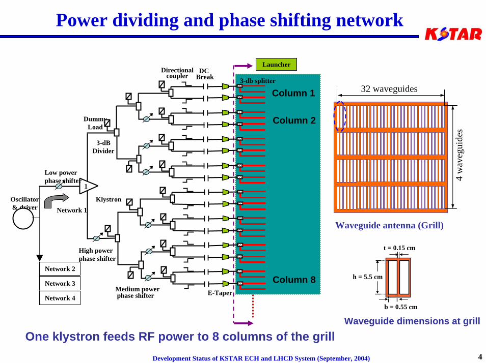
Power dividing and phase shifting network
Directionalcoupler
DC Break
Oscillator& driver
Low power phase shifter
High powerphase shifter
Medium powerphase shifter E-Taper
DummyLoad
Klystron
3-dBDivider
1
Launcher
Network 1
Network 2
3-db splitter
Network 3
Network 4
Waveguide antenna (Grill)
32 waveguides
4 w
aveg
uide
s
Column 1
Column 2
Column 8 h = 5.5 cm
b = 0.55 cm
t = 0.15 cm
Waveguide dimensions at grillOne klystron feeds RF power to 8 columns of the grill
Development Status of KSTAR ECH and LHCD System (September, 2004) 5
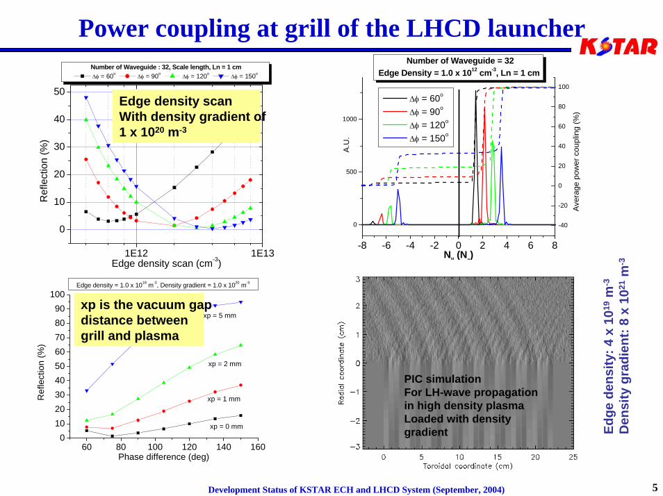
Power coupling at grill of the LHCD launcher
1E12 1E13
0
10
20
30
40
50
Ref
lect
ion
(%)
Edge density scan (cm-3)
Number of Waveguide : 32, Scale length, Ln = 1 cm ∆φ = 60o ∆φ = 90o ∆φ = 120o ∆φ = 150o
-8 -6 -4 -2 0 2 4 6 8
0
500
1000
-40
-20
0
20
40
60
80
100
A.U
.
N|| (Nz)
∆φ = 60o
∆φ = 90o
∆φ = 120o
∆φ = 150o
Number of Waveguide = 32Edge Density = 1.0 x 1012 cm-3, Ln = 1 cm
Aver
age
pow
er c
oupl
ing
(%)
60 80 100 120 140 1600
102030405060708090
100
xp = 5 mm
xp = 2 mm
xp = 1 mm
xp = 0 mm
Ref
lect
ion
(%)
Phase difference (deg)
Edge density = 1.0 x 10¹⁸ m-3, Density gradient = 1.0 x 10²⁰ m-3
Edge density scanWith density gradient of1 x 1020 m-3
xp is the vacuum gapdistance betweengrill and plasma
PIC simulationFor LH-wave propagationin high density plasmaLoaded with density gradient Ed
ge d
ensi
ty: 4
x 1
019
m-3
Den
sity
gra
dien
t: 8
x 10
21m
-3
Development Status of KSTAR ECH and LHCD System (September, 2004) 6
Design progress of 5.0-GHz LHCD launcher
• Conceptual physics design of the single waveguide channel has been done (using HFSS and ANSYS)– E-plane taper– 3-dB power splitter– Fixed phase shifter– Water-load
• Co-work with PPPL for the KSTAR launcher design– It has many of the design feature of C-MOD launcher (5 sec operation)– However, the near steady-state of KSTAR operation (300 sec) presents
some new challenges which will require new launcher design features• Better heat removal from the coupler grill• Shielding of the microwave windows from direct line of sight to the plasma • Compact water loads for capturing power reflected from the grill/plasma
interface– The collaboration with PPPL is expected to provide a suitable steady-state
launcher design for KSTAR.– A reasonable cooling structure is presented by Dr. J. Hosea in US-KO
collaboration meeting, May 19.
Development Status of KSTAR ECH and LHCD System (September, 2004) 7
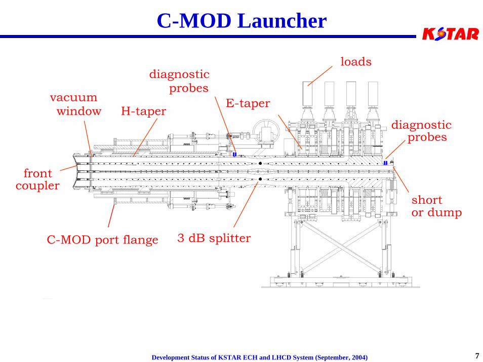
C-MOD Launcher
frontcoupler
vacuum window H-taper
3 dB splitter
E-taper
shortor dump
loadsdiagnostic
probes
diagnosticprobes
C-MOD port flange
Development Status of KSTAR ECH and LHCD System (September, 2004) 8
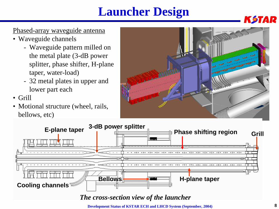
Launcher DesignPhased-array waveguide antenna• Waveguide channels
- Waveguide pattern milled on the metal plate (3-dB power splitter, phase shifter, H-plane taper, water-load)
- 32 metal plates in upper and lower part each
• Grill• Motional structure (wheel, rails,
bellows, etc)
The cross-section view of the launcher
E-plane taper 3-dB power splitterGrillPhase shifting region
Bellows H-plane taperCooling channels
Development Status of KSTAR ECH and LHCD System (September, 2004) 9
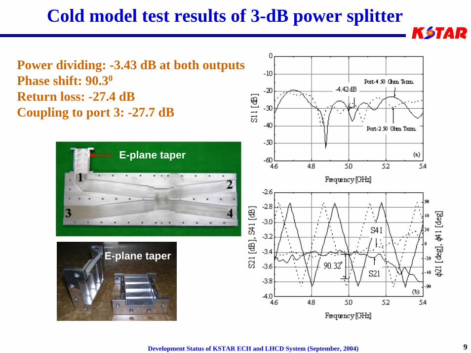
Cold model test results of 3-dB power splitter
Power dividing: -3.43 dB at both outputs Phase shift: 90.30
Return loss: -27.4 dBCoupling to port 3: -27.7 dB
E-plane taper
E-plane taper
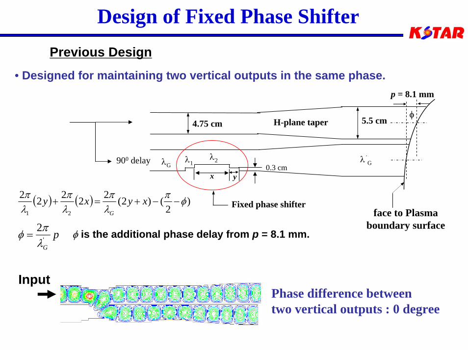
Design of Fixed Phase ShifterPrevious Design
• Designed for maintaining two vertical outputs in the same phase.p = 8.1 mm
face to Plasmaboundary surface
( ) ( ) )2
()2(22222
21
φπλπ
λπ
λπ
−−+=+ xyxyG
pG'
2λπφ =
Phase difference betweentwo vertical outputs : 0 degree
Input
H-plane taper
Fixed phase shifter
5.5 cm4.75 cm
x y
λ1λ2 λ′GλG900 delay
φ
0.3 cm
φ is the additional phase delay from p = 8.1 mm.
Development Status of KSTAR ECH and LHCD System (September, 2004) 11
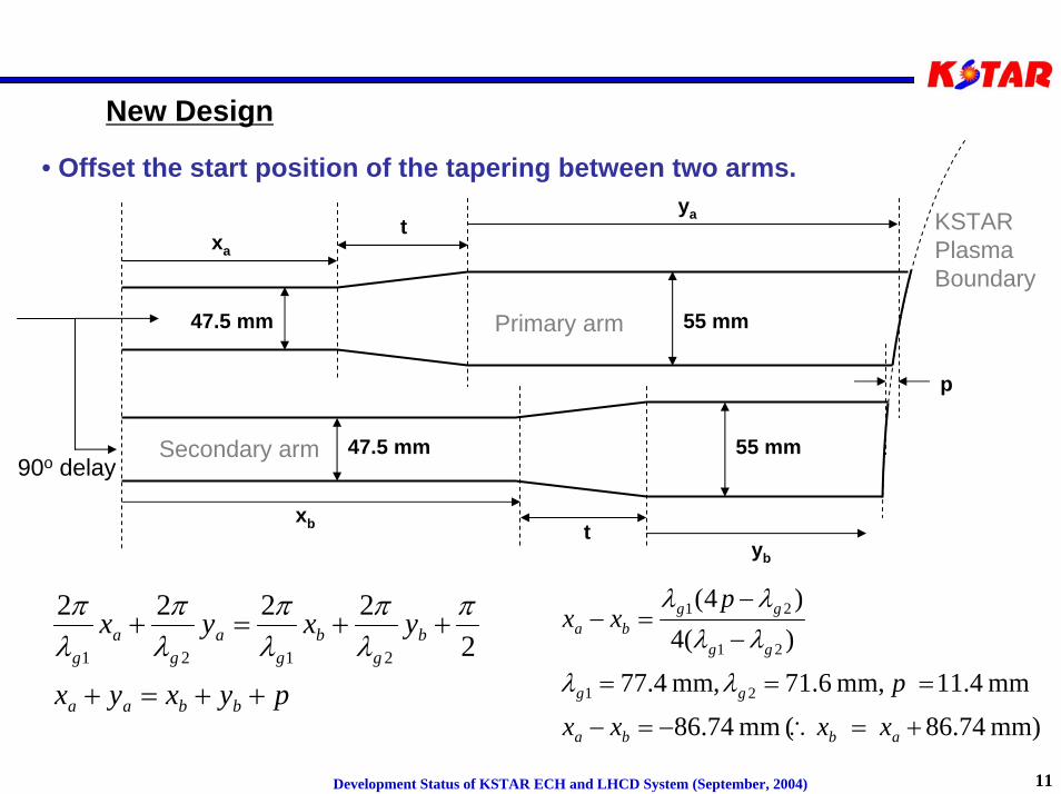
New Design
pyxyx
yxyx
bbaa
bg
bg
ag
ag
++=+
++=+2
2222
2121
πλπ
λπ
λπ
λπ
tyb
xb
p
ya
xat
47.5 mm
47.5 mm 55 mm
55 mm
Primary arm
Secondary arm90o delay
KSTARPlasmaBoundary
• Offset the start position of the tapering between two arms.
mm) 86.74( mm 86.74
mm 11.4 mm, 71.6,mm 77.4
)(4)4(
21
21
21
+=∴−=−
===
−
−=−
abba
gg
gg
ggba
x xxx
p
pxx
λλ
λλλλ
Development Status of KSTAR ECH and LHCD System (September, 2004) 12
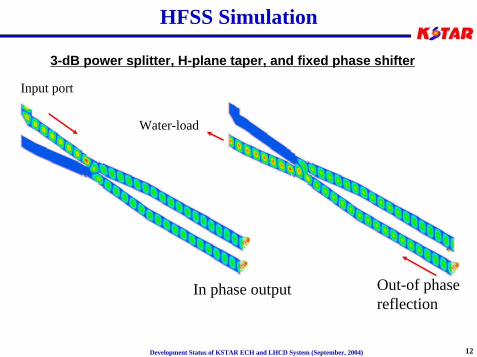
HFSS Simulation
3-dB power splitter, H-plane taper, and fixed phase shifter
Input port
In phase output Out-of phasereflection
Water-load
Development Status of KSTAR ECH and LHCD System (September, 2004) 13
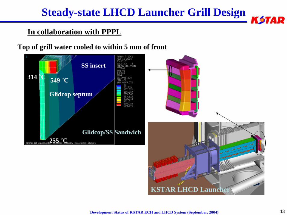
Steady-state LHCD Launcher Grill Design
In collaboration with PPPL
Top of grill water cooled to within 5 mm of front
Glidcop septum
255 °C
SS insert
314 °C 549 °C
Glidcop/SS Sandwich
KSTAR LHCD Launcher
Development Status of KSTAR ECH and LHCD System (September, 2004) 14
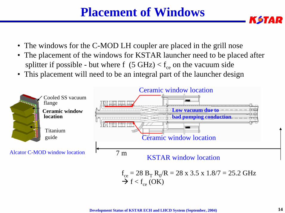
Placement of Windows
• The windows for the C-MOD LH coupler are placed in the grill nose• The placement of the windows for KSTAR launcher need to be placed after
splitter if possible - but where f (5 GHz) < fce on the vacuum side• This placement will need to be an integral part of the launcher design
Cooled SS vacuum flangeCeramic windowlocation
Titanium guide
Alcator C-MOD window locationKSTAR window location
Ceramic window location
Ceramic window location
7 m
Low vacuum due to bad pumping conduction
fce = 28 BT R0/R = 28 x 3.5 x 1.8/7 = 25.2 GHzf < fce (OK)
Development Status of KSTAR ECH and LHCD System (September, 2004) 15
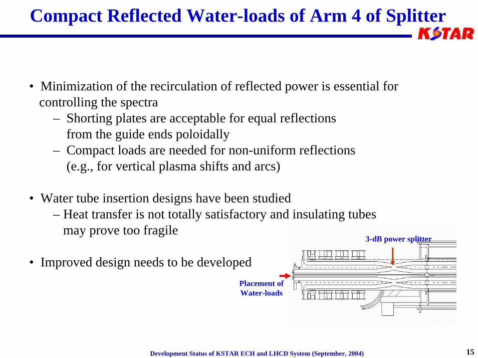
Compact Reflected Water-loads of Arm 4 of Splitter
• Minimization of the recirculation of reflected power is essential for controlling the spectra
– Shorting plates are acceptable for equal reflections from the guide ends poloidally
– Compact loads are needed for non-uniform reflections(e.g., for vertical plasma shifts and arcs)
• Water tube insertion designs have been studied– Heat transfer is not totally satisfactory and insulating tubes
may prove too fragile
• Improved design needs to be developed
3-dB power splitter
Placement ofWater-loads
Development Status of KSTAR ECH and LHCD System (September, 2004) 16
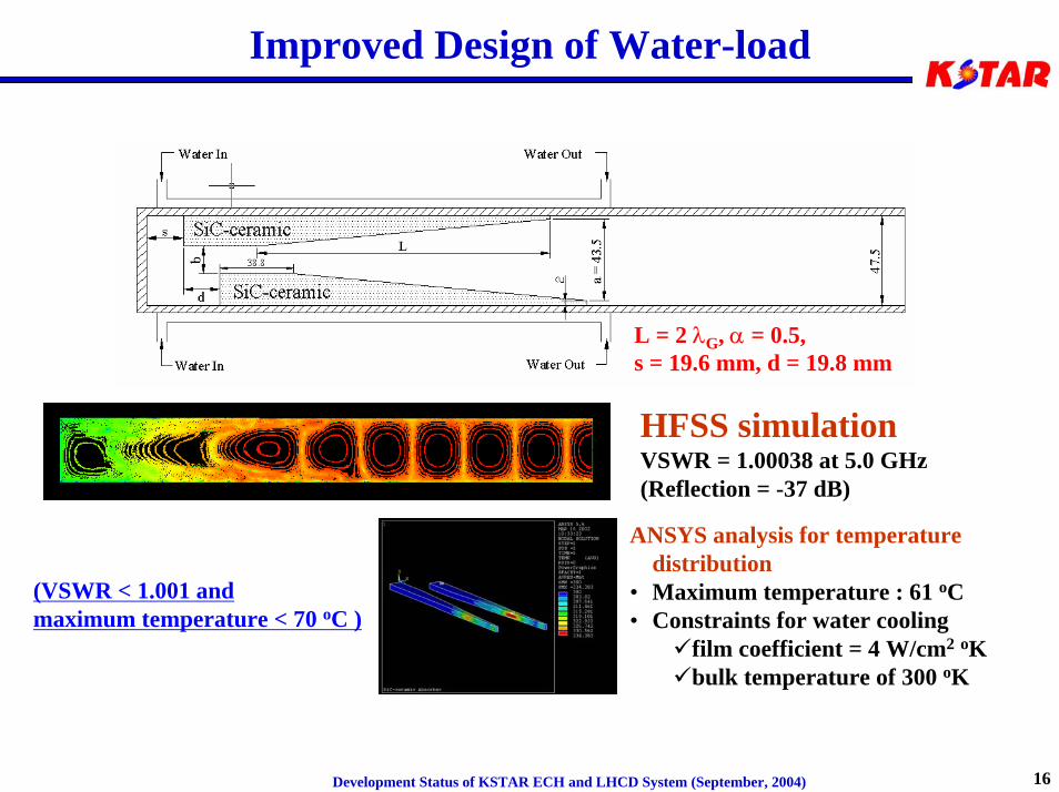
Improved Design of Water-load
L = 2 λG, α = 0.5, s = 19.6 mm, d = 19.8 mm
HFSS simulationVSWR = 1.00038 at 5.0 GHz(Reflection = -37 dB)
ANSYS analysis for temperature distribution
• Maximum temperature : 61 oC• Constraints for water cooling
film coefficient = 4 W/cm2 oKbulk temperature of 300 oK
(VSWR < 1.001 and maximum temperature < 70 oC )
Development Status of KSTAR ECH and LHCD System (September, 2004) 17
Summary and proposal alternatives for US support
• We propose to help address the important steady-state LH launcher issues– Design, analyze and prototype (at high power) fully active grills that can sustain
steady-state operation on KSTAR - a Glidcop/SS sandwich design is probably best for heat/disruption loads
– Design proper placement of windows out-of-sight of plasma– Develop new compact water load for arm 4 of splitter - design and
prototype (low and high power)
This task is estimated to take two years at ~ $400 k per year
• We could also undertake to design and fabricate the entire LH launcher for KSTAR– This would involve integrating the designs above into a splitter/guide
arrangement that would fit into the KSTAR port envelope– Most likely a three-way splitter poloidally would be designed so that the
number of windows could be reduced to 32 and could all be placed inside theport space
This task is roughly estimated to take ~ 3 years after the development aboveand to cost ~ $5 M in as spent dollars with 30% contingency.
Development Status of KSTAR ECH and LHCD System (September, 2004) 18
Proposed schedule and cost by PPPL
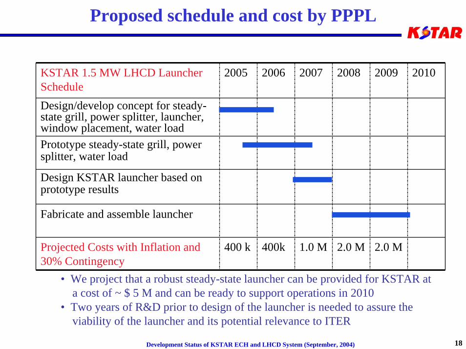
KSTAR 1.5 MW LHCD Launcher Schedule
2005 2006 2007 2008 2009 2010
Design/develop concept for steady-state grill, power splitter, launcher,window placement, water load
Projected Costs with Inflation and 30% Contingency
400 k 400k 1.0 M 2.0 M 2.0 M
Prototype steady-state grill, power splitter, water load
Design KSTAR launcher based on prototype results
Fabricate and assemble launcher
• We project that a robust steady-state launcher can be provided for KSTAR at a cost of ~ $ 5 M and can be ready to support operations in 2010
• Two years of R&D prior to design of the launcher is needed to assure theviability of the launcher and its potential relevance to ITER
Development Status of KSTAR ECH and LHCD System (September, 2004) 19
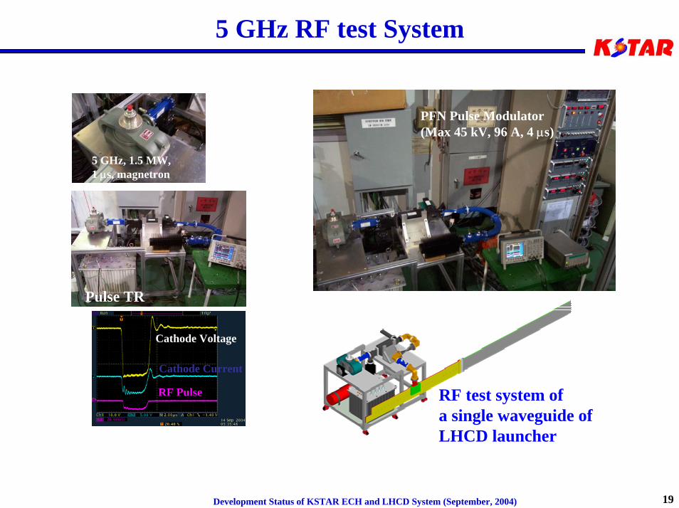
5 GHz RF test System
RF test system ofa single waveguide ofLHCD launcher
PFN Pulse Modulator(Max 45 kV, 96 A, 4 µs)
5 GHz, 1.5 MW,1 µs, magnetron
Pulse TR
Cathode Voltage
Cathode Current
RF Pulse
Development Status of KSTAR ECH and LHCD System (September, 2004) 20
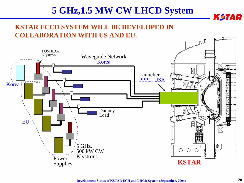
5 GHz,1.5 MW CW LHCD System
TOSHIBAKlystron
Power Supplies
5 GHz, 500 kW CWKlystrons
LauncherPPPL, USA
KSTAR
Korea
Waveguide NetworkKorea
EU
DummyLoad
KSTAR ECCD SYSTEM WILL BE DEVELOPED IN COLLABORATION WITH US AND EU.