itb formation with counter eccd and lhcd and suprathermal ... · itb formation with counter eccd...
TRANSCRIPT

ITB formation with counter ECCD and LHCD and Suprathermal ECCD experiments on FTU in ITER relevant conditions
C Sozzi1, G Granucci1, S Nowak1, A Bruschi1, D Farina1, F Gandini1, L Panaccione2, V Pericoli-Ridolfini2, B Angelini2, S V Annibaldi2, M L Apicella2, G Apruzzese2, E Barbato2, P Buratti2, G Calabrò2,C Castaldo2, S Cirant1, M De Benedetti2, J Berrino1, A Bertocchi2, A Cardinali2, L Carraro3, C Centioli2, R Cesario2, V Cocilovo2, F Crisanti2, R DeAngelis2, F De Marco2, B Esposito2, D Frigione2, L Gabellieri2, E Giovannozzi2, F Iannone2, H Kroegler2, E Lazzaro1, M Leigheb2, M Marinucci2, D Marocco2, G Mazzitelli2, C Mazzotta2, F Mirizzi2, G Monari2, F Orsitto2, D Pacella2, M Panella2, L Pieroni2, S Podda2, M E Puiatti3, G Ravera2, G Regnoli2, G B Righetti2, F Romanelli2, M Romanelli2, A Simonetto1, P Smeulders2, E Sternini2, B Tilia2, O Tudisco2, A A Tuccillo2, V Vitale2, G Vlad2 and F Zonca2. 1Istituto di Fisica del Plasma, EURATOM-ENEA-CNR Association, Milano, Italy. 2Associazione EURATOM-ENEA sulla Fusione, CR Frascati, Roma, Italy 3Consozio RFX, EURATOM-ENEA-CNR Association, Padova, Italy E-mail: [email protected] Abstract: In this paper the results of the experiments of combined injection of LH waves and EC waves performed in the FTU tokamak are reported. Such experiments were mainly devoted to study and to control the access to the advanced tokamak scenarios in plasma conditions close to ITER parameters (Bt≈5T or higher, ne,line≈1020 m-3). Two different absorption mechanisms were used for the EC waves. In the first one the cold resonance absorption of EC waves launched with a toroidal angle was used to induce small modification of the current profile mainly maintained by LH waves. In the second one the absorption through Doppler shift due to the fast electron tails generated by LHCD was used.
PACS code: 52.55.Wq 1. Introduction LH and EC wave radiofrequency heating and current drive systems have been used for long time in the fusion science devices, and their strong and weak points are well known. (See [1, 2] and references therein for recent reviews). However, their combined injection has been little studied and its potential use in present and future fusion devices is still far from full exploitation. The CD studies are one of the main task for FTU, exploiting the non-usual contemporary availability of the LHCD system (8GHz up to 2.4MW) and of the ECRH system (140 Ghz, 1.6MW) [3]. This makes possible a wide range of combined-injection applications, including the control of the plasma current profile in order to access advanced tokamak confinement regimes and the study of non conventional absorption schemes of the radiofrequency waves at toroidal magnetic field and plasma density in the very range of ITER. Operation with ITBs is one of the most promising tokamak regimes to be implemented in present and future fusion machines due to the superior energy confinement properties reached thorough the suppression of microinstabilities in at least one layer in the plasma core. ITB’s physics and formation dynamic have been extensively studied in all the major fusion experiments in the world [4]. In this frame the FTU tokamak has a particular role, due to the high range of toroidal magnetic field (4-8 T), to its high plasma density (1020 m-3 or higher) and to the
Institute of Physics Publishing Journal of Physics: Conference Series 25 (2005) 198–209doi:10.1088/1742-6596/25/1/025 Third IAEA Technical Meeting on ECRH Physics and Technology in ITER
198© 2005 IOP Publishing Ltd

presence of strong electron heating that results, in presence of electron ITB, in outstanding electron temperatures at plasma density high enough to involve indirect ion heating. Different ITB formation schemes have been used in FTU tokamak, and most of them (but not all) use combined injection of LH and ECRH. The “classical” scheme includes full (or partial) non inductive plasma current sustained with LHCD during the plateau phase and injection of ECRH in pure heating configuration (with no toroidal angle). Even though this scheme has been successfully demonstrated [5,6], its performance in terms of maximum plasma current and density attainable in the ITB regime and in terms of barrier radial width were limited by the amount of CD power available and by its poor control capability of the details of the resulting current profile, i.e. the radial position of low or negative magnetic shear regions. Such a control capability is a valuable goal in the advanced tokamak physics. The combined injection of LHCD and ECCD (co-current and counter-current) can be used as a tool to increase the reliability of this plasma scenario and give an important contribution to access and maintain the ITB regime even at higher performance. The direct absorption of EC wave by fast electron generated by LHCD is expected to have higher cd-efficiency if compared with the classic ECCD [7] This theoretical prediction has been previously confirmed by different experiments [8,9,10], and opens the perspective to design experimental scenarios tailored in order to take advantage of it. The wide range of toroidal magnetic field of FTU (4 – 8 T) allows in principle to test both the interaction mechanisms: the up-shifted resonance (BT< Bres =5 T) and the down-shifted (BT> Bres = 5T) ones. Clear evidences of the upshift interaction scheme can be obtained if the cold resonance layer and the LHCD deposition region, where the fast electron are generated, are well separated and if the EC wave beam crosses the suprathermal electrons region in the plasma before the dumping due to the cold resonance layer. This scheme, with its enhanced ECCD efficiency, could be advantageously applied in ITER provided that the suprathermal population could be maintained in some way. Unfortunately the upshift interaction in FTU is quite difficult to put in evidence due to the small radial dimension of the machine (R0=.935m; a = 0.28 m). Otherwise the downshift scheme is easily realized, simply increasing the toroidal magnetic field until the cold resonance is brought outside of the plasma. Accordingly with the theory, the suprathermal cd efficiency in the two schemes is expected to be of the same order of magnitude [11], and therefore experimental results obtained in the downshift scheme can be used at least for a raw evaluation of the effects in ITER, even if in a different absorption scheme. 2. Role of ECCD with resonant absorption in the ITB formation in reactor relevant conditions Electron cyclotron current driven on-axis in counter direction to the plasma current (CNT-ECCD) has been used on FTU tokamak in combination with Lower Hybrid Current Drive (LHCD) in order to obtain the Internal Transport Barrier (ITB) during the current plateau phase (Ip≈360 kA) at plasma density and magnetic field close to ITER parameters (ne0≥1.4 1020 m-3, B0=5.3 T, Te0>5.5 KeV). These ITBs are remarkably stronger of the “classic” ones, i.e. obtained using ECR power for pure heating, and usually they are long lasting, terminated by the power switch-off and not by MHD events. Their energy transport characteristics both in the electron and in the ion channels and the possible relationship with the reduction of the turbulence at long poloidal wavenumbers are described in reference [12] while the specific role of the cnt-ECCD in tailoring a current profile suitable for the ITBs formation is pointed out in the present paper. An interesting point that is worthy to mention, in view of similar application in future devices as well, is the very small amount of driven current that determines quite different plasma time evolutions. In fact the low overall EC current drive efficiency, of the order of 0.01*1020 AW-1m-2 as measured in a dedicated experiments in FTU [13], corresponds to ICNT-ECCD≈15-20 kA for 1.1MW injected EC power in the experiments here reported. Nevertheless the narrow localization of the ECW absorption and driven current density effectively modify the magnetic equilibrium configuration in the plasma core. This modification has been confirmed reversing the ECCD contribution in otherwise very similar plasma shots, producing in that way evident alteration of the sawteeth dynamics. The temporal evolution of the central electron temperature is shown in figure 1. In all these shots the LH power (1.4 MW in 26671 and 26662, 1.1 MW in 26661 and 26673) is switched on during the plasma current plateau at 0.5s, anticipated by an ohmic phase with well
199

developed sawteeth activity. The ECH power (1.1MW in all cases) is switched on with a 0.1s delay with respect to LH. The radial deposition profile of LHCD, derived from Fast Electron
#26671
#26673
#26661
#26662
Co-ECCD
Perp
Perp
Time (s) Time (s)0.4 0.6 0.8 1.0 0.70 0.72 0.74 0.76 0.78 0.80
EC
E T
empe
ratu
re (A
.U.)
a)
b)
c)
d)
Cnt-ECCD
ECRH ON/OFF
LH ON/OFF
#26671
#26673
#26661
#26662
Co-ECCD
Perp
Perp
Time (s) Time (s)0.4 0.6 0.8 1.0 0.70 0.72 0.74 0.76 0.78 0.80
EC
E T
empe
ratu
re (A
.U.)
a)
b)
c)
d)
Cnt-ECCD
ECRH ON/OFF
LH ON/OFF
Figure 1. On left: ECE temperature time evolution for a set of similar plasma shots with different EC injections: a) Cnt-ECCD; b) and c) Perpendicular injection; d) Co-ECCD. On right: zoom of the marked time window. Bremsstrahlung diagnostic, is broad with its peak at 5 cm from the magnetic axis. The radial deposition of ECCD, calculated with the ECWGB code [14] is about 2 cm FWHM and centred at 2-3 cm from the magnetic axis, well inside the q=1 surface. The sawteeth activity is stopped in the case of counter current injection only (shot 26671, -10° toroidal angle). In the case of perpendicular injection the sawteeth are temporarily suppressed (shots 26662 and 26661), and in the co-injection case (shot 26673, +10° toroidal angle) the activity is accentuated. The LH power normalized to the plasma line density is higher in shots 26671 and 26662 than in shots 26661 and 26673, and this observation confirms that the effect on sawteeth dynamics has to be ascribed to cnt-ECCD. This behaviour is consistent with the modification of the safety factor profile in the plasma core, as pointed out with the interpretative, time dependent transport analysis performed with the JETTO code and reported in figures 2 and 3. In this analysis the power densities, the electron temperature and the current densities are taken from measurements or from independent calculation, whereas the local transport and the current density and related quantities are consistently derived. Figure 2 shows the relevant plasma profiles at 0.7s for the shots 26671 and 26673. The non RF driven components of the current density are shown in row d) for the cnt-ECCD and co-ECCD experiment respectively, and the safety factor profiles q(r) in the row e). The combined injection of LHCD and ECCD introduces a non monotonic behaviour of the q profile both in co and cnt-ECCD cases. However, in the cnt-case the resulting minimum of the profile is significantly higher than in co-case and shifted outward. This contributes to reduce detrimental MHD activity, and then strengthens the ITBs. The perpendicular injection case (LHCD plus pure ECRH) has been included for comparison as well in the row e). Figures 3a) and 3c) show the temporal evolution of the safety factor profile for the same shots 26671 and 26673, cnt-ECCD and co-ECCD respectively. Coherently with the long lasting characteristics
200

observed in the cnt-ECCD ITBs, the central section of the safety factor profile is continuously rising during the power injection with respect to the q=1 level (figure 3a). This is not verified in co-ECCD
[email protected] [email protected]
PLHCD
Ti
JLHCD
q
PECCD
PLHCD
JLHCD
q
a)
b)
c)
d)
e)qmin qmin perp inj.
co- inj.
Te Te
Ti
Jco-ECCD
Jcnt-ECCD
[email protected] [email protected]
PLHCD
Ti
JLHCD
q
PECCD
PLHCD
JLHCD
q
a)
b)
c)
d)
e)qmin qmin perp inj.
co- inj.
Te Te
Ti
Jco-ECCD
Jcnt-ECCD
Figure 2. JETTO code transport analysis for cnt-ECCD (left) and co-ECCD (right). From top to bottom: a) ECCD and b) LHCD power density radial deposition; c) Electron and ion temperatures; d) Driven current densities; e) Safety factor profile. Shaded areas denote region where the calculation is inaccurate. case (figure 3c). The simulation of the pure ECRH case in figure 2b) confirms that the perpendicular injection combined with LHCD injection is unable to shape the details of the safety factor profile. In this case the central part of the profile is slightly risen due to LHCD, but it is only marginally above q=1 and strictly depending on the amount of the available LHCD power for the given plasma density. The role of the central ECCD in shaping the details of the current density profile is further specified in figure 4, where all the components of the current density are plotted for the 26671 shot. The cnt-ECCD contribution counterbalances the residual inductive current in the central region of the plasma, where the LHCD deposition profile is usually hollow. The effect of the on axis CNT-ECCD combined with LHCD in increasing the strength and the duration of the ITB through the reduction of the MHD activity here described resembles previous results obtained in TCV tokamak [15] using a different technique, i.e. ECRH off axis and cnt-ECCD. A second promising configuration for LHCD+ECCD experiments includes co-ECCD at higher toroidal angle (+30°) and therefore resulting in an off axis deposition even if the magnetic field and
201

the poloidal steering are unchanged with reference to the experiments above reported. This is the case of the shot 27273 (5.3 T, 0.6 MA, 1.5 MW LHCD, 1.1 MW co-ECCD) whose the Thomson Scattering
2
1
2
1
2
1
0 0.05 0.1 0.15ro (m)
26671 - cntECCD
26673 - coECCD
t=0.6s
t=0.7st=0.8s
t=0.5s
t=0.6st=0.7st=0.8s
t=0.5s
t=0.8st=0.7st=0.6st=0.5s
a)
b)
c)
2
1
2
1
2
1
0 0.05 0.1 0.15ro (m)
26671 - cntECCD
26673 - coECCD
t=0.6s
t=0.7st=0.8s
t=0.5s
t=0.6st=0.7st=0.8s
t=0.5s
t=0.8st=0.7st=0.6st=0.5s
a)
b)
c)
Figure 3. Evolution of the safety factor profiles during cnt-ECCD (a), pure ECRH (b) and co-ECCD (c). Shaded areas denote region where the calculation is inaccurate.
ro(m)
0.25
JOH+Jcnt-ECCD
Jcnt-ECCD
JTOTJLH JBS
JOH #26671 @ t=0.7 s
A/m
2
ro(m)
0.25
JOH+Jcnt-ECCD
Jcnt-ECCD
JTOTJLH JBS
JOH #26671 @ t=0.7 s
A/m
2
Figure 4. JETTO code transport analysis. Current densities components for cnt-ECCD shot 26671. Small box in bottom right presents the case of on axis deposition.
202

t=0.50-0.54s
t=0.56-0.62sBarrier
JcoECCD deposition27273T
e(K
eV)
2
0
4
6
2
0
3
1
z (m)0-0.1-0.2-0.3 0.1
10-2
Magn. axis
ρ*Tρ*Te =0.014
a)
b)
t=0.50-0.54s
t=0.56-0.62sBarrier
JcoECCD deposition27273T
e(K
eV)
2
0
4
6
2
0
3
1
z (m)0-0.1-0.2-0.3 0.1
z (m)0-0.1-0.2-0.3 0.1
10-2
Magn. axis
ρ*Tρ*Te =0.014
a)
b)
Figure 5. 1.5 MW co-ECCD at 30° injection angle. a) Te profiles from Thomson Scattering at different time slices before (0.50-0.54s) and during (0.56-0.62s) co-ECCD. b) ρ*T criterion applied to the Te profile above during the co-ECCD phase. temperature profiles are shown in figure 5a. The co-current deposition aids to flatten the magnetic shear of the larger q profile, due to the higher plasma current with respect of the previous experiments, moving outward the barrier foot. This is confirmed applying the so-called ρ*T criterion as shown in figure 5b, reckoning the existence of a transport barrier when the normalized inverse temperature scale length ρ*T=ρL,s/LT>0.014 where ρL,s is the Larmor radius of the ions moving at the sound velocity and LT=Te/(dTe/dr) [16]. Accordingly to this criterion, the region extending from r/a= 0.3 to r/a=0.65 presents a mild ITB feature. 3. Suprathermal ECCD experiments The suprathermal absorption of EC wave has been widely used on FTU. The routinely availability of more than 1 MW of EC and 1.5 MW of LHCD power has in fact opened the possibility of new experiments after the pioneering proof of principle obtained in the past at lower power level (0.4 MW) [9]. The most used suprathermal EC absorption scheme on FTU is the resonant at downshifted frequencies, in which the EC wave (140 GHz) is injected in a plasma with toroidal field well above the resonant one (5T). The presence in the plasma of fast electrons allows the resonant interaction to occur at frequencies shifted up or down with respect to the cold resonance, depending on the launched N//EC and on v// (parallel speed of electrons). The fast electron population, which directly absorbs the EC power, is generated and sustained by LHCD in plasmas with line density in the range 0.6 - 1.0 1020m-3 and current 400 - 800 kA.
203

Figure 6. Solutions of resonant equation for EC waves with different toroidal injection angles. Figure 6 shows the solutions in cv /|| , the normalized velocity of the electron in the suprathermal tail, of the resonant moment equation for EC waves with different toroidal injection angles with respect to the electron direction as given by the equation:
( ) ⎟⎟⎠
⎞⎜⎜⎝
⎛−
−=
Ω
||
||
2||
||
/1
1/
/vc
N
vc
vc EC
o
ec
ω (1)
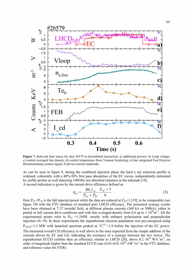
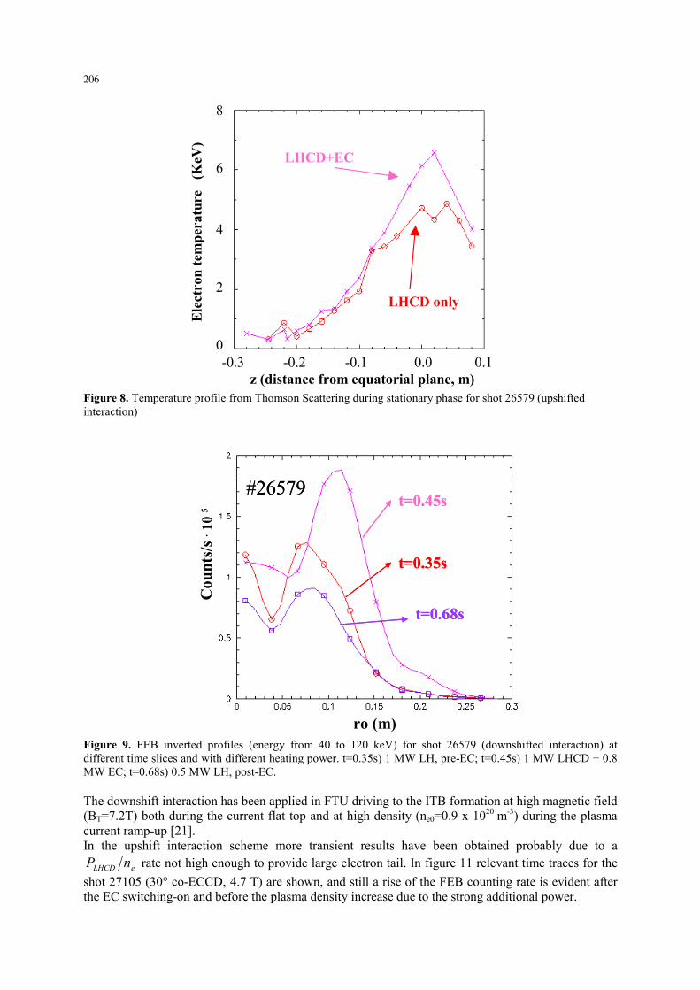
Here LHCDNvc //||/ = and vpar>>vperp are assumed. The two branches of the synergy interaction, representing the minimum and the maximum resonant momentum, are plotted as a function of the Ωec/ω0 ratio, being Ωec the electron cyclotron cold resonance angular frequency, ω0 the wave frequency and ( )TECN ϑsin|| = , where Tϑ is the toroidal angle of launch of the ECCD. The downshifted absorption condition is verified with B > 5T with perp. or cnt-cd injection, the upshifted absorption B<5T with co-cd injection. The driven current is in co-direction in both the cases. Figure 7 shows the time traces for the upshift experiment realized in shot 26579 at 7.2T, 0.5 MA, 0.6 1020 m-3 averaged line density, with perpendicular EC injection (PEC= 1.1 MW, O-Mode) and PLH= ~ 1 MW, n//=1.52, where the 5.3T “cold” resonance is outside of the plasma. Besides the remarkable effect on the electron temperature profile (figure 8), the signatures of the possible effectiveness of the absorption during the synergy phase are given by the signal of the Fast Electron Bremsstralung (FEB) camera (15 chords - 8 energy levels 20-200 KeV) [17] and by the amplitude of the non inductively driven current ICD by
⎟⎟⎠
⎞⎜⎜⎝
⎛
><
><−⋅=
cd
oh
ohe
cde
oh
cdPCD Zeff
ZeffTT
VloopVloopII 2/3
_
2/3_1 (2)
which gives the Icd term from the loop voltage reduction, compensated of the resistive change induced by Zeff and by volume averaged temperature (<Te3/2>) variations. However both the previous pieces of information are requiring deeper analysis to separate true synergy from effects due to standard LHCD application. One of such additional confirmations comes from the counts radial distribution of the FEB camera.
204
Te0
FEB
ne,line
Vloop
I_cd
#26579
ECLHCD
Time (s)0.40.3 0.5 0.6
A
Cou
nts
KeV
m-3
V
W
a)
b)
c)
d)
e)
f)
Te0
FEB
ne,line
Vloop
I_cd
#26579
ECLHCD
Time (s)0.40.3 0.5 0.6
A
Cou
nts
KeV
m-3
V
W
a)
b)
c)
d)
e)
f)
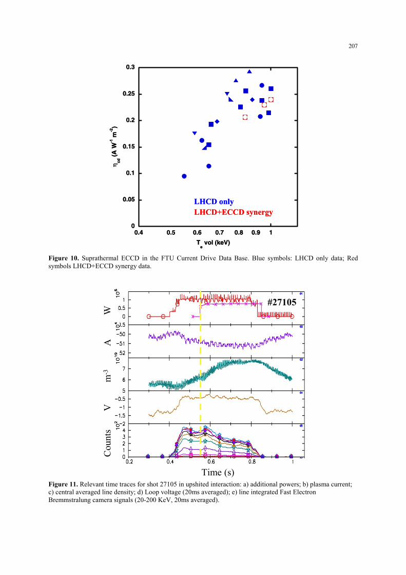
Figure 7. Relevant time traces for shot 26579 in downshited interaction: a) additional powers; b) Loop voltage; c) central averaged line density; d) central temperature from Tomson Scattering; e) line integrated Fast Electron Bremmstralung camera signal; f) driven current amplitude. As can be seen in figure 9, during the combined injection phase the hard x ray emission profile is widened, coherently with a 40%-50% first pass absorption of the EC waves, independently estimated by sniffer probes as well detecting 140GHz not absorbed radiation in the tokamak [18]. A second indication is given by the current drive efficiency defined as
65+
+= eff
ECLH
cdecd
ZPPInRη . (3)
Here PEC+PLH is the full injected power while the data are reduced at Zeff=1 [19], to be comparable (see figure 10) with the FTU database of standard pure LHCD efficiency. The presented synergy results have been obtained at 7.1T toroidal field, at different plasma currents (360 kA or 500kA), either in partial or full current drive conditions and with line averaged density from 0.6 up to 1 1020m-3. All the experimental points refer to PEC =1.1MW, mostly with ordinary polarization and perpendicular injection (N//=0). In these experiments the suprathermal electron population was pre-energized using PLHCD=1.2 MW with launched spectrum peaked at LHN // =1.8 before the injection of the EC power. The measured overall CD efficiency is well above to the ones expected from the simple addition of the currents driven by EC and LH, indicating the existence of a synergy between the two waves. The suprathermal ECCD exhibits then an efficiency similar to LHCD [20], above 0.2 1020 WA-1m-2, an order of magnitude higher than the standard ECCD case (0.01-0.02 1020 AW-1m-2 in the FTU database, and reference value for ITER).
205
LHCD+EC
LHCD only
Ele
ctro
n te
mpe
ratu
re
(KeV
)
-0.3 -0.2 -0.1 0.0 0.1z (distance from equatorial plane, m)
0
2
4
6
8
LHCD+EC
LHCD only
Ele
ctro
n te
mpe
ratu
re
(KeV
)
-0.3 -0.2 -0.1 0.0 0.1z (distance from equatorial plane, m)
0
2
4
6
8
Figure 8. Temperature profile from Thomson Scattering during stationary phase for shot 26579 (upshifted interaction)
#26579
t=0.35s
t=0.45s
t=0.68s
Cou
nts/
s·10
5
ro (m)
#26579
t=0.35s
t=0.45s
t=0.68s
Cou
nts/
s·10
5
ro (m) Figure 9. FEB inverted profiles (energy from 40 to 120 keV) for shot 26579 (downshifted interaction) at different time slices and with different heating power. t=0.35s) 1 MW LH, pre-EC; t=0.45s) 1 MW LHCD + 0.8 MW EC; t=0.68s) 0.5 MW LH, post-EC. The downshift interaction has been applied in FTU driving to the ITB formation at high magnetic field (BT=7.2T) both during the current flat top and at high density (ne0=0.9 x 10²⁰ m-3) during the plasma current ramp-up [21]. In the upshift interaction scheme more transient results have been obtained probably due to a
eLHCD nP rate not high enough to provide large electron tail. In figure 11 relevant time traces for the shot 27105 (30° co-ECCD, 4.7 T) are shown, and still a rise of the FEB counting rate is evident after the EC switching-on and before the plasma density increase due to the strong additional power.
206
0
0.05
0.1
0.15
0.2
0.25
0.3
0.4 0.5 0.6 0.7 0.8 0.9 1
η cd (
A W
-1 m
-2)
Te vol (keV)
LHCD onlyLHCD+ECCD synergy
0
0.05
0.1
0.15
0.2
0.25
0.3
0.4 0.5 0.6 0.7 0.8 0.9 1
η cd (
A W
-1 m
-2)
Te vol (keV)
LHCD onlyLHCD+ECCD synergy
Figure 10. Suprathermal ECCD in the FTU Current Drive Data Base. Blue symbols: LHCD only data; Red symbols LHCD+ECCD synergy data.
#27105
Time (s)
Cou
nts
Vm
-3A
W
#27105
Time (s)
#27105#27105
Time (s)
Cou
nts
Vm
-3A
W
Figure 11. Relevant time traces for shot 27105 in upshited interaction: a) additional powers; b) plasma current; c) central averaged line density; d) Loop voltage (20ms averaged); e) line integrated Fast Electron Bremmstralung camera signals (20-200 KeV, 20ms averaged).
207

However, the experimental situation is not that clear in such case, due to the shorter suprathermal interaction length. Only 5-7 cm walk across the LHCD driven electron tail are allowed before the EC wave is damped by the cold resonance close to the plasma centre. This is reflected in the radial Hard X emission profile in figure 12 where the presence of the double peaking reveals a more complex situation with respect to the downshift case.
t=0.520 s (before ECH start)
t=0.580 s (ECH start)t=0.600 s
t=0.620
t=0.700#27105
ro(m)
coun
ts/s
t=0.520 s (before ECH start)
t=0.580 s (ECH start)t=0.600 s
t=0.620
t=0.700#27105
ro(m)
coun
ts/s
Figure 12. FEB inverted profiles for shot 27105 (upshifted interaction) at different time slices and with different heating power. 4. Conclusions The experiments above reported underline the potential of the combined use of EC and LH waves in order to access/control the advanced tokamak scenarios. In combined LHCD+ECCD injection with EC resonant absorption, the localization of the EC driven current appears to be effective in triggering the ITB formation through “surgical” modification of the local magnetic shear. Cnt-ECCD experiment in ITB shows that 4-5% of the full current driven in the right radial position plays a relevant role, provided that the “general” shape is built with LHCD, or other possible alternative ways. The synergy interaction scheme presents a surprising enhancing of the EC current drive efficiency, raised to typical pure-LHCD values. This scenario could be used to generate significant amount of non-inductive current for sustaining plasma in future devices. Beyond these demonstration experiments, these scenarios require further development in present devices in order to explore higher performance regimes and gain the necessary reliability. One of the key aspects in this development is the generation and control of the suprathermal electron population. With the ECH system for ITER (170 GHz) at present foreseen, the upshift scheme is potentially exploitable, provided that fast electron tails are sustained in some way.
208

References [1] A.Tuccillo et al., 2005, 32nd EPS Plasma Physics Conference, I5.004. [2] T.Luce, 2002, IEEE Trans.Plasma Scie.,Vol. 30, No.3, p.734. [3] A. Tuccillo et al., May 2004 Fus. Sc. and Techn. Vol. 45, p. 459. [4] C.Challis, 2004, Plasma Phys. Control. Fusion 46 B23–B40. [5] V.Pericoli-Ridolfini et al., 2004, Fus. Sc. and Techn. Vol. 45, p. 323. [6] V.Pericoli-Ridolfini et al., 2003 Nucl. Fusion 43, p. 469. [7] D.Farina, R. Pozzoli, 1989, Phys. Fluids B 1 (5), p. 815. [8] G. Granucci et al., Proc.12th W. on ECE and ECRH, Aix-en-Prov., (France), 341 (2002). [9] V.Pericoli-Ridolfini et al, Proc. 14th RFPP, Oxnard, (USA),225-232, (2001). [10] G. Giruzzi et al., Phys. Rev. Lett. 93, 255002 (2004). [11] D.Farina, R. Pozzoli, 1989, Phys. Fluids B 1 (5), 1042. [12] V.Pericoli-Ridolfini et al., Febr 2005, 4th IAEA Technical Meeting on Steady State Operations, 2005. [13] S.Nowak et al., 2005, 32nd EPS Plasma Physics Conference, paper P1.095. [14] S.Nowak , E. Lazzaro , G. Ramponi, 1996, Phys. Plasmas 3, 4140. [15] Z. A. Pietrzyk, C. Angioni, R. Behn, S. Coda, T. P. Goodman, M. A. Henderson, F. Hofmann, and O. Sauter, 2001, Phys.Rev.Lett, 86, n. 8, p. 1530 . [16] G. Tresset et al., 2002, Nucl. Fusion, Vol. 42, 520–526 [17] O.Tudisco et al., 2004, Fus. Sc. and Techn. Vol. 45, p. 402. [18] F.Gandini et al., 2001 Fusion Eng. and Design 56-57, 975. [19] J.Fisch, 1987, Rev. Modern Phys., Vol.59, 175. [20] G.Granucci et al., 2004, Fus. Sc. and Techn. Vol. 45, p.387. [21] B.Angelini et al, Overview of FTU Results, to be published on Nuclear Fusion.
209