development of wound rotor synchronous motor for belt
TRANSCRIPT
Journal of Magnetics 18(4), 487-493 (2013) http://dx.doi.org/10.4283/JMAG.2013.18.4.487
© 2013 Journal of Magnetics
Development of Wound Rotor Synchronous Motor for Belt-Driven e-Assist System
Geun-Ho Lee*, Heon-Hyeong Lee, and Qi Wang
Graduate School of Automotive Engineering, Kookmin University, Seoul 136-702, Korea
(Received 15 October 2013, Received in final form 22 November 2013, Accepted 25 November 2013)
The automotive industry is showing widespread interest in belt-driven electric motor–assisted (e-Assist)
systems. A belt-driven assist system (BAS) starts and assists the combustion engine in place of the conventional
generator. In this study, a water-cooled wound rotor synchronous motor (WRSM) for the e-Assist system was
designed and analyzed. The performance of the WRSM was compared with that of an interior permanent
magnet synchronous motor (IPMSM). The WRSM efficiency can be improved for the BAS by adjusting the
field flux at high speeds. The field current map to obtain the maximum efficiency based on the speed and
torque was developed. To control the field flux via field current control in the WRSM, a general H-bridge
circuit was added to the WRSM inverter to get the rapid current response in the high-speed region; the
characteristics were compared with the chopper circuit. A WRSM developed for the belt-driven e-Assist system
and a prototype 115 V power electronic converter to drive the WRSM were tested with a 900 cc combustion
engine. The test results showed that the WRSM-type e-Assist system had good characteristics and could
successfully start and assist the 900 cc combustion engine.
Keywords: e-Assist system, wound rotor synchronous motor, integrated starter and generator, PWM inverter
1. Introduction
The belt-driven assist system (BAS) is gaining attention
for use in mild hybrid electric vehicles (HEVs). The idle
stop and go function of the BAS is important in areas
with heavy traffic such as urban streets. Idle stop ceases
engine operation in order to eliminate fuel consumption
and emissions when the vehicle stops temporarily. After
an idle stop, the engine is restarted automatically by the
BAS motor. A BAS increases the vehicle fuel economy
and comprises an electric machine, power electronics, a
controller, and a 115 V battery. Using belt-driven e-Assist
(electric motor–assisted) systems was found to improve
the fuel economy of vehicles by more than 10% when
driving in the city [1, 2].
Because replacing the 12 V DC generator mounted on
the combustion engine with the BAS allows the conv-
entional engine room structure to be retained, many auto-
motive engineers are interested in adopting the BAS.
The belt-driven e-Assist system provides starting, gene-
rating, torque-assisting, and three-phase pulse-width modu-
lation (PWM) converter functions for regenerative braking
[2, 3]. During starting mode, the machine operates at low
speed and is self-driven with torque control; it operates at
maximum torque for sufficiently fast cranking. In gene-
rating mode, the converter can operate in synchronous
rectifier mode or three-phase PWM converter mode with
the torque regulation function [3, 4].
Electric machines currently employ drives based on
permanent magnet synchronous motors (PMSMs) or
induction motors for BAS. Induction motors and PMSMs
can be driven with a proper power electronic converter.
These kinds of drives can only reach very high torque at
low speeds through the injection of very high current in
the machine stator windings. Electromagnetic flux control
methodology must be used to drive the motor at very high
speeds. PMSM motors are widely adopted in electric and
hybrid vehicles. However, the cost is very expensive because
of the permanent magnet, and the efficiency is reduced at
high speeds owing to the weakened flux. For induction
motors, flux control can be adopted at high speeds; how-
ever, guaranteeing high torque at low speed is difficult.
Recently, the wound rotor synchronous motor (WRSM)
has received a great deal of attention for automotive
applications requiring robustness and high-speed operation.
It is a cost-effective motor that does not use permanent
©The Korean Magnetics Society. All rights reserved.
*Corresponding author: Tel: +82-2-910-4721
Fax: +82-2-910-4718, e-mail: [email protected]
ISSN (Print) 1226-1750ISSN (Online) 2233-6656
− 488 − Development of Wound Rotor Synchronous Motor for Belt-Driven e-Assist System… − Geun-Ho Lee et al.
magnets.
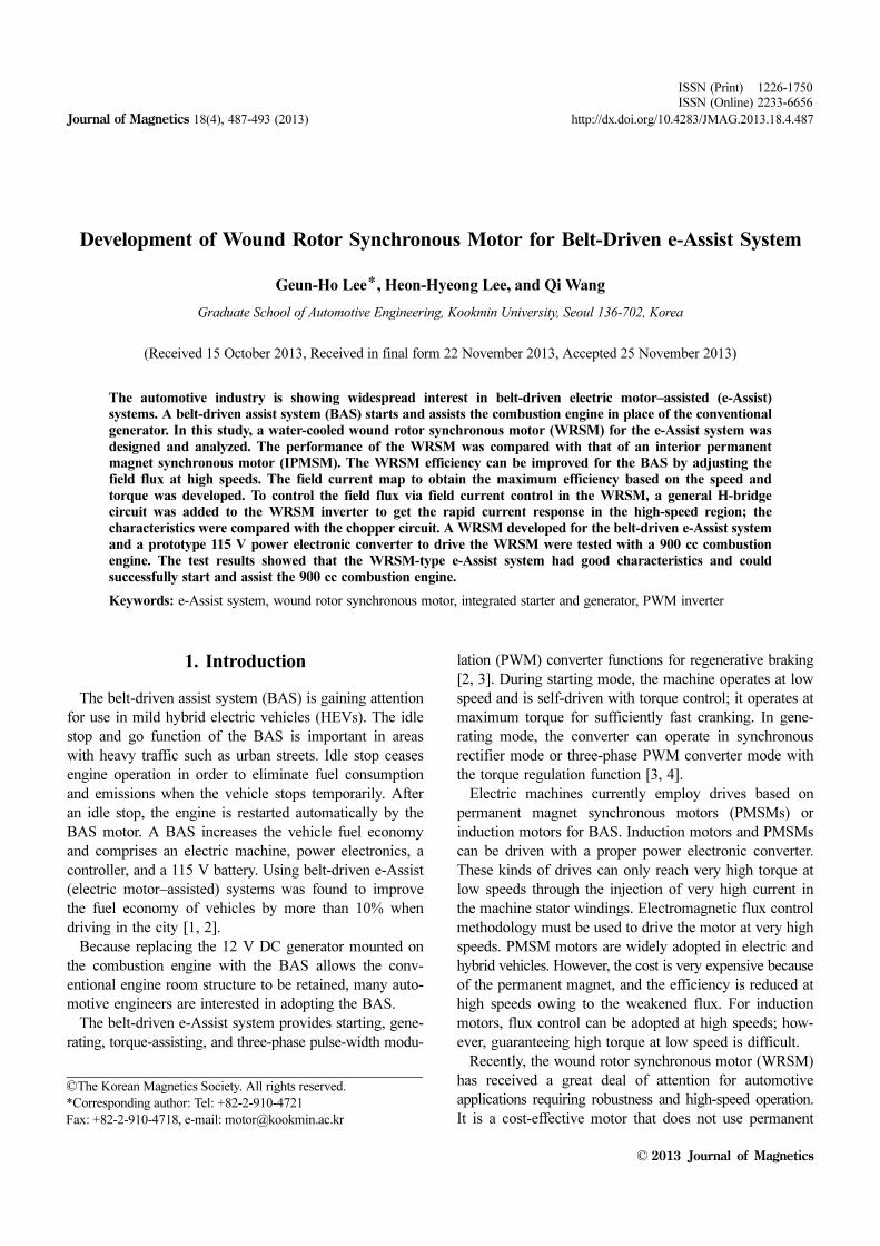
In this study, a WRSM for a belt-driven e-Assist system
was developed, as shown in Fig. 1, and compared with an
interior permanent magnet synchronous motor (IPMSM).
A prototype 115 V power electronic converter to drive the
WRSM was developed and tested with a combustion
engine. Field control in the WRSM was found to be very
important to change speeds rapidly and protect the power
electronics; the H-bridge circuit was compared to the
chopper circuit for field control. A 900 cc combustion
engine with the WRSM prototype was tested and analyzed.
2. Design of Wound Rotor Synchronous Motor for Belt-driven e-Assist System
2.1. Structure of Wound Rotor Synchronous Motor
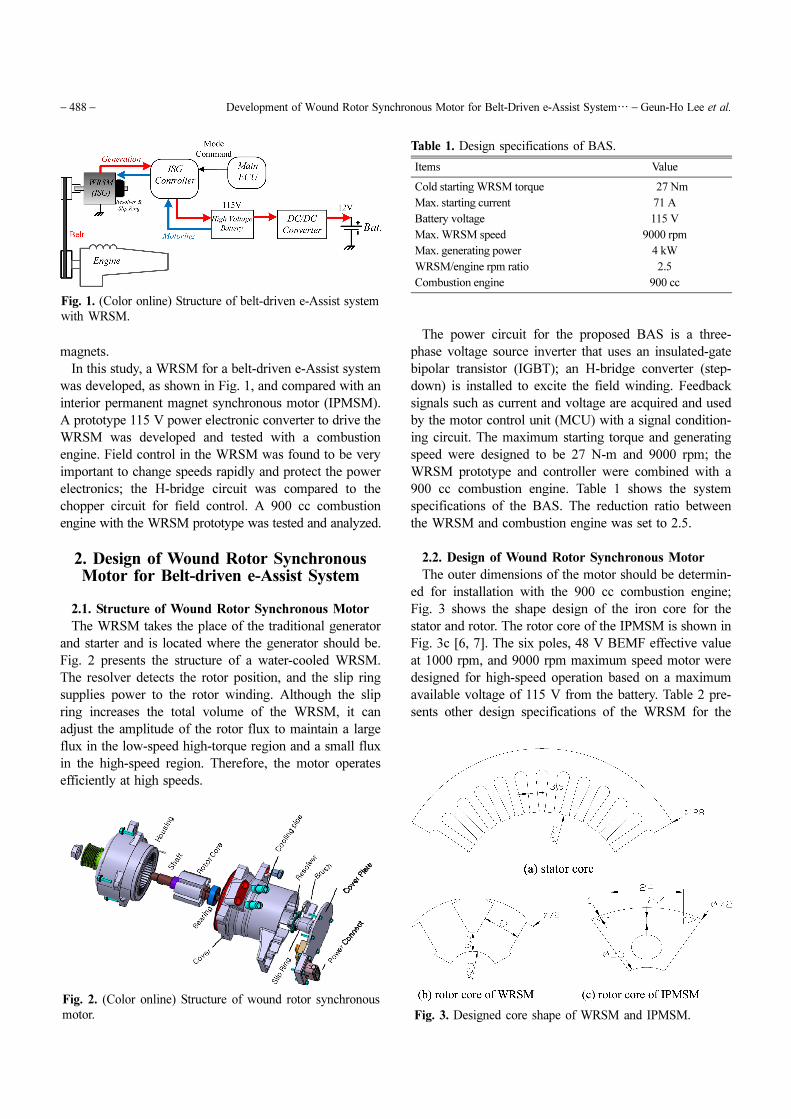
The WRSM takes the place of the traditional generator
and starter and is located where the generator should be.
Fig. 2 presents the structure of a water-cooled WRSM.
The resolver detects the rotor position, and the slip ring
supplies power to the rotor winding. Although the slip
ring increases the total volume of the WRSM, it can
adjust the amplitude of the rotor flux to maintain a large
flux in the low-speed high-torque region and a small flux
in the high-speed region. Therefore, the motor operates
efficiently at high speeds.
The power circuit for the proposed BAS is a three-
phase voltage source inverter that uses an insulated-gate
bipolar transistor (IGBT); an H-bridge converter (step-
down) is installed to excite the field winding. Feedback
signals such as current and voltage are acquired and used
by the motor control unit (MCU) with a signal condition-
ing circuit. The maximum starting torque and generating
speed were designed to be 27 N-m and 9000 rpm; the
WRSM prototype and controller were combined with a
900 cc combustion engine. Table 1 shows the system
specifications of the BAS. The reduction ratio between
the WRSM and combustion engine was set to 2.5.
2.2. Design of Wound Rotor Synchronous Motor
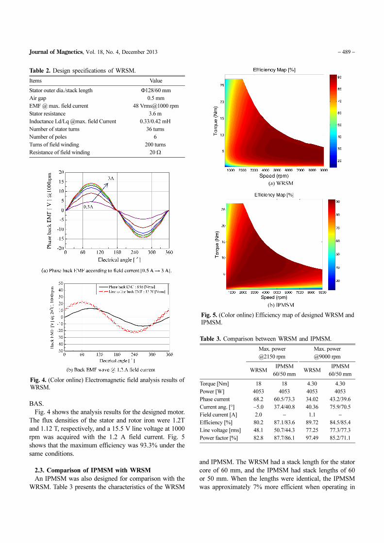
The outer dimensions of the motor should be determin-
ed for installation with the 900 cc combustion engine;
Fig. 3 shows the shape design of the iron core for the
stator and rotor. The rotor core of the IPMSM is shown in
Fig. 3c [6, 7]. The six poles, 48 V BEMF effective value
at 1000 rpm, and 9000 rpm maximum speed motor were
designed for high-speed operation based on a maximum
available voltage of 115 V from the battery. Table 2 pre-
sents other design specifications of the WRSM for the
Fig. 1. (Color online) Structure of belt-driven e-Assist system
with WRSM.
Fig. 2. (Color online) Structure of wound rotor synchronous
motor.
Table 1. Design specifications of BAS.
Items Value
Cold starting WRSM torque 27 Nm
Max. starting current 71 A
Battery voltage 115 V
Max. WRSM speed 9000 rpm
Max. generating power 4 kW
WRSM/engine rpm ratio 2.5
Combustion engine 900 cc
Fig. 3. Designed core shape of WRSM and IPMSM.
Journal of Magnetics, Vol. 18, No. 4, December 2013 − 489 −
BAS.
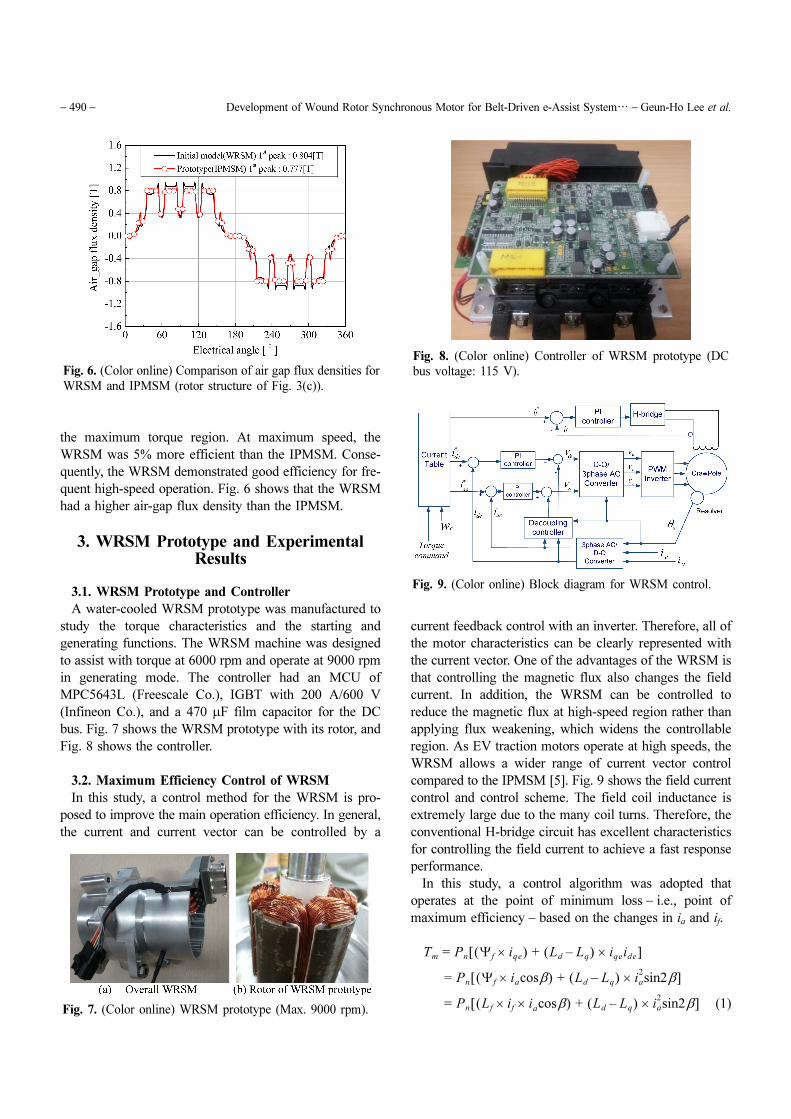
Fig. 4 shows the analysis results for the designed motor.
The flux densities of the stator and rotor iron were 1.2T
and 1.12 T, respectively, and a 15.5 V line voltage at 1000
rpm was acquired with the 1.2 A field current. Fig. 5
shows that the maximum efficiency was 93.3% under the
same conditions.
2.3. Comparison of IPMSM with WRSM
An IPMSM was also designed for comparison with the
WRSM. Table 3 presents the characteristics of the WRSM
and IPMSM. The WRSM had a stack length for the stator
core of 60 mm, and the IPMSM had stack lengths of 60
or 50 mm. When the lengths were identical, the IPMSM
was approximately 7% more efficient when operating in
Table 2. Design specifications of WRSM.
Items Value
Stator outer dia./stack length Φ128/60 mm
Air gap 0.5 mm
EMF @ max. field current 48 Vrms@1000 rpm
Stator resistance 3.6 m
Inductance Ld/Lq @max. field Current 0.33/0.42 mH
Number of stator turns 36 turns
Number of poles 6
Turns of field winding
Resistance of field winding
200 turns
20 Ω
Fig. 4. (Color online) Electromagnetic field analysis results of
WRSM.
Fig. 5. (Color online) Efficiency map of designed WRSM and
IPMSM.
Table 3. Comparison between WRSM and IPMSM.
Max. power
@2150 rpm
Max. power
@9000 rpm
WRSMIPMSM
60/50 mmWRSM
IPMSM
60/50 mm
Torque [Nm] 18 18 4.30 4.30
Power [W] 4053 4053 4053 4053
Phase current 68.2 60.5/73.3 34.02 43.2/39.6
Current ang. [°] −5.0 37.4/40.8 40.36 75.9/70.5
Field current [A] 2.0 − 1.1 −
Efficiency [%] 80.2 87.1/83.6 89.72 84.5/85.4
Line voltage [rms] 48.1 50.7/44.3 77.25 77.3/77.3
Power factor [%] 82.8 87.7/86.1 97.49 85.2/71.1
− 490 − Development of Wound Rotor Synchronous Motor for Belt-Driven e-Assist System… − Geun-Ho Lee et al.
the maximum torque region. At maximum speed, the
WRSM was 5% more efficient than the IPMSM. Conse-
quently, the WRSM demonstrated good efficiency for fre-
quent high-speed operation. Fig. 6 shows that the WRSM
had a higher air-gap flux density than the IPMSM.
3. WRSM Prototype and Experimental Results
3.1. WRSM Prototype and Controller
A water-cooled WRSM prototype was manufactured to
study the torque characteristics and the starting and
generating functions. The WRSM machine was designed
to assist with torque at 6000 rpm and operate at 9000 rpm
in generating mode. The controller had an MCU of
MPC5643L (Freescale Co.), IGBT with 200 A/600 V
(Infineon Co.), and a 470 μF film capacitor for the DC
bus. Fig. 7 shows the WRSM prototype with its rotor, and
Fig. 8 shows the controller.
3.2. Maximum Efficiency Control of WRSM
In this study, a control method for the WRSM is pro-
posed to improve the main operation efficiency. In general,
the current and current vector can be controlled by a
current feedback control with an inverter. Therefore, all of
the motor characteristics can be clearly represented with
the current vector. One of the advantages of the WRSM is
that controlling the magnetic flux also changes the field
current. In addition, the WRSM can be controlled to
reduce the magnetic flux at high-speed region rather than
applying flux weakening, which widens the controllable
region. As EV traction motors operate at high speeds, the
WRSM allows a wider range of current vector control
compared to the IPMSM [5]. Fig. 9 shows the field current
control and control scheme. The field coil inductance is
extremely large due to the many coil turns. Therefore, the
conventional H-bridge circuit has excellent characteristics
for controlling the field current to achieve a fast response
performance.
In this study, a control algorithm was adopted that
operates at the point of minimum loss − i.e., point of
maximum efficiency − based on the changes in ia and if.
(1)
Tm = Pn Ψf iqe×( ) + Ld Lq–( ) iqe× ide[ ]
= Pn Ψf iacosβ×( ) + Ld Lq–( ) ia2
× sin2β[ ]
= Pn Lf if i× acosβ×( ) + Ld Lq–( ) ia2
× sin2β[ ]
Fig. 6. (Color online) Comparison of air gap flux densities for
WRSM and IPMSM (rotor structure of Fig. 3(c)).
Fig. 7. (Color online) WRSM prototype (Max. 9000 rpm).
Fig. 8. (Color online) Controller of WRSM prototype (DC
bus voltage: 115 V).
Fig. 9. (Color online) Block diagram for WRSM control.
Journal of Magnetics, Vol. 18, No. 4, December 2013 − 491 −
(2)
(3)
(4)
where Ψf is the rotor flux, Tm is the torque, iqe is the q-axis
current, ide is the d-axis current, ia is the phase current, if is
the field current, Lf is the field inductance, Pn is the pole
pair, and Ld, Ld are the stator inductances.
Equations (1) and (2) represent the relationship between
the stator current and magnetic flux at the same torque
level. Eq. (4) expresses the sum of the stator copper
losses and field copper losses, or the total copper losses of
the WRSM. In the WRSM, iron losses do not have as
much influence as the copper losses and were thus dis-
regarded. ia
and if can be determined with the same torque
and minimum losses by examining the changes in the
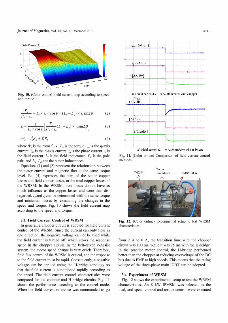
speed and torque. Fig. 10 shows the field current map
according to the speed and torque.
3.3. Field Current Control of WRSM
In general, a chopper circuit is adopted for field current
control of the WRSM. Since the current can only flow in
one direction, the negative voltage cannot be used while
the field current is turned off, which slows the response
speed in the chopper circuit. In the belt-driven e-Assist
system, the motor speed change is very quick. Therefore,
field flux control of the WRSM is critical, and the response
to the field current must be rapid. Consequently, a negative
voltage can be applied using the H-bridge topology so
that the field current is conditioned rapidly according to
the speed. The field current control characteristics were
compared for the chopper and H-bridge circuits. Fig. 11
shows the performance according to the control mode.
When the field current reference was commanded to go
from 2 A to 0 A, the transition time with the chopper
circuit was 100 ms, while it was 25 ms with the H-bridge.
In the practice motor control, the H-bridge performed
better than the chopper at reducing overvoltage of the DC
bus due to EMF at high speeds. This means that the rating
voltage of the three-phase main IGBT can be adopted.
3.4. Experiment of WRSM
Fig. 12 shows the experimental setup to test the WRSM
characteristics. An 8 kW IPMSM was selected as the
load, and speed control and torque control were executed
Tm
Pn ia×--------------- = Lf if× cosβ× Ld Lq–( ) ia× sin2β+
if = 1
Lf cosβ×-----------------------
Tm
Pn ia×--------------- Ld Lq–( ) ia× sin2β
Wc = ia2Ra + if
2Rf
Fig. 10. (Color online) Field current map according to speed
and torque.
Fig. 11. (Color online) Comparison of field current control
methods.
Fig. 12. (Color online) Experimental setup to test WRSM
characteristics.
− 492 − Development of Wound Rotor Synchronous Motor for Belt-Driven e-Assist System… − Geun-Ho Lee et al.
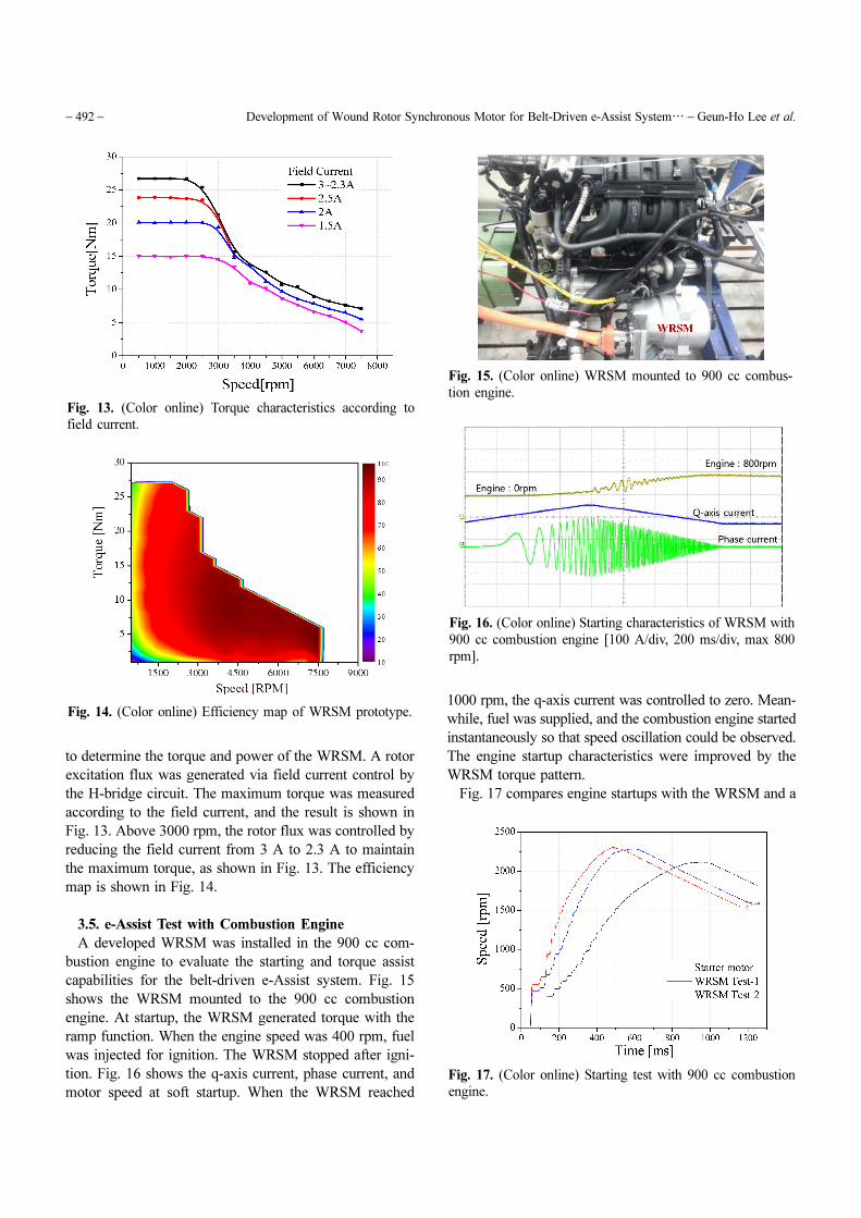
to determine the torque and power of the WRSM. A rotor
excitation flux was generated via field current control by
the H-bridge circuit. The maximum torque was measured
according to the field current, and the result is shown in
Fig. 13. Above 3000 rpm, the rotor flux was controlled by
reducing the field current from 3 A to 2.3 A to maintain
the maximum torque, as shown in Fig. 13. The efficiency
map is shown in Fig. 14.
3.5. e-Assist Test with Combustion Engine
A developed WRSM was installed in the 900 cc com-
bustion engine to evaluate the starting and torque assist
capabilities for the belt-driven e-Assist system. Fig. 15
shows the WRSM mounted to the 900 cc combustion
engine. At startup, the WRSM generated torque with the
ramp function. When the engine speed was 400 rpm, fuel
was injected for ignition. The WRSM stopped after igni-
tion. Fig. 16 shows the q-axis current, phase current, and
motor speed at soft startup. When the WRSM reached
1000 rpm, the q-axis current was controlled to zero. Mean-
while, fuel was supplied, and the combustion engine started
instantaneously so that speed oscillation could be observed.
The engine startup characteristics were improved by the
WRSM torque pattern.
Fig. 17 compares engine startups with the WRSM and a
Fig. 13. (Color online) Torque characteristics according to
field current.
Fig. 14. (Color online) Efficiency map of WRSM prototype.
Fig. 15. (Color online) WRSM mounted to 900 cc combus-
tion engine.
Fig. 16. (Color online) Starting characteristics of WRSM with
900 cc combustion engine [100 A/div, 200 ms/div, max 800
rpm].
Fig. 17. (Color online) Starting test with 900 cc combustion
engine.

Journal of Magnetics, Vol. 18, No. 4, December 2013 − 493 −
conventional DC starter motor. The WRSM was tested at
different pulley ratios: 2.5:1 (test 1) and 2.14:1 (test 2).
The WRSM startup time of test 1 was about 50 ms shorter
than that of test 2. The engine startup with WRSM was
better than that with the conventional DC starter motor;
thus, the idle stop and go function of BAS had good
characteristics.
The e-Assist system played a critical role in increasing
the automotive efficiency via motor torque assistance in
the low speed region, where the engine had low effici-
ency. The torque assist experiment was conducted from
1000 rpm to 3500 rpm in the engine idle state. Fig. 18
depicts the torque assist characteristics at pulley ratios of
2.5:1 and 2.14:1. The experiments showed that a high
torque assist can be acquired and that the system had
good torque characteristics. The pulley ratio of the WRSM
can be determined according to the engine efficiency test
results.
4. Conclusions
In this study, a WRSM was developed for a belt-driven
e-Assist system, and a prototype 115 V power electronic
converter to drive the WRSM was designed and tested
with a 900 cc combustion engine. The test results showed
that the WRSM-type e-Assist system had good characteri-
stics and could successfully start and assist the 900 cc
combustion engine.
The field current of the WRSM could be controlled to
reduce the magnetic rotor flux at high speeds with the H-
bridge converter, which widened the controllable region.
The H-bridge converter could adjust the field current
from 2.5 A to 0 A within 25 ms, which is acceptable.
The WRSM was 20% larger than the IPMSM in volume,
but it was 5% more efficient at high speeds. Therefore,
the WRSM can be used as a substitute for the IPMSM in
the belt-driven e-Assist system with a small increase in
volume and reduced cost.
To reduce the WRSM volume as an e-Assist compo-
nent, the machine needs to be designed to have a higher
flux density to obtain a high starting torque. With regard
to the starting torque, the rotor volume of the WRSM
prototype must be increased to maximize the flux density
at startup.
Acknowledgement
This work was supported by global scholarship program
for foreign graduated student at Kookmin University in
korea.
References
[1] G. Friedrich and A. Girardin, IEEE Ind. Appl. Mag. 12, 26
(2009).
[2] J. E. Walters and R. J. Krefta, SAE World Congress, Mar.
(2004).
[3] Geun-Ho Lee, Geo-Seung Choi, and Woong-chul Choi,
JPE. 11, 527 (2011).
[4] J. Liu, J. Hu, and L. Xu, IEEE Ind. Appl. Confer. 2754
(2004).
[5] B. W. Lee, thesis, Hanyang University (2013).
[6] Tao Sun, Ji-Min Kim, Geun-Ho Lee, Jung-Pyo Hong, and
Myung-Ryul Choi, IEEE Trans. Magn. 47, 1038 (2011).
[7] Jae-Woo Jung, Jung-Pyo Hong, and Young-Kyoun Kim, in
Proc. VPPC, 778 (2007).
Fig. 18. (Color online) Torque assist test with 900 cc combus-
tion engine.