overhaul electrical auxiliary rotating...
TRANSCRIPT

MLCA STD SPEC 3141_STD {Supersedes 3141_STD, 2001 Edition}
OVERHAUL ELECTRICAL ROTATING MACHINES
1. SCOPE
1.1 Scope. This standard specification describes the requirements for the Contractor to overhaul electrical rotating machines onboard Coast Guard vessels.
1.2 Applicability. The work specified in this standard specification applies to auxiliary motors and generators, and ship service and emergency generators, but not to electric propulsion rotating machines.
1.3 Appendices. The following appendices apply to this standard specification:
TITLE APPENDIX
Table for Round Film Insulated Magnet Wire (J-W-1177) A
Table for Square and Rectangular Film Insulated Magnet Wire (J-W-1177) B
Table for Flexible Insulation Sheet C
Table for Insulating Sleeving D
Table for Laminated Uninsulated Sheet (U/I LB) E
Table for Lacing and Tying Tape F
Table for Insulation Tape (U/I Roll) G
Table for Lead Wire (MIL-DTL-16878) H
Table for Varnish Insulation I
Table for Slot Wedge Insulation J
2. APPLICABLE DOCUMENTS
Commercial Item Description (CID) A-A-52083, Feb 2004, Tape,
2004 Edition 1 3141
Downloaded from http://www.everyspec.com

MLCA STD SPEC 3141_STD {Supersedes 3141_STD, 2001 Edition}
Lacing and Tying, Glass
Commercial Item Description (CID) A-A-52084, Jun 2003, Tape, Lacing and Tying
Commercial Item Description (CID) A-A-59133, Nov 1997, Cleaning Compound, High Pressure (Steam) Cleaner
MIL-I-631, Insulation, Electrical, Jun 1987, Synthetic Resin Composition, Non-Rigid
MIL-I-695, Nov 1972, Insulation, Electrical, Paper (Slot Cell
MIL-I-3190, Insulation Sleeving, Aug 1993, Electrical, Flexible, Coated, General Specification for
MIL-I-3505, Oct 1960, Insulation Sheet and Tape, Electrical, Coil and Slot, High Temperature
MIL-I-15126, Apr 2003, Insulation Tape, Electrical, Pressure Sensitive Adhesive and Pressure Sensitive Thermosetting Adhesive
MIL-DTL-16878, Wire, Electrical, Aug 2000, Insulated, General Specification for
MIL-I-19166, Oct 1988, Insulation Tape, Electrical, High Temperature, Glass Fiber, Pressure Sensitive
MIL-I-21070, May 1966, Insulation Sheet and Tape, Electrical, Reinforced Mica Paper
MIL-I-22834, Apr 1998, Insulation, Electrical, Dielectric Barrier, Laminated, Plastic Film and Synthetic Fiber Material
MIL-I-24092, Sept 1993, Insulating Varnishes and Solventless Resins for Application by the Dip Process
MIL-I-24204, Aug 2002, Insulation, Electrical, High Temperature, Bonded Synthetic Fiber Paper
MIL-I-24391, Aug 1991, Insulation Tape, Electrical, Plastic, Pressure Sensitive
MIL-I-24718, Jun 1993, Insulation Resins, Solventless, Vacuum-Pressure-Impregnation; General Specification for
MIL-I-24768, Dec 1992, Insulation, Plastics, Laminated, Thermosetting; General Specification for
MIL-I-24768/1, Dec 1992, Insulation, Plastic, Laminated, Thermosetting, Glass-Cloth, Melamine-Resin(GME)
2004 Edition 2 3141
Downloaded from http://www.everyspec.com

MLCA STD SPEC 3141_STD {Supersedes 3141_STD, 2001 Edition}
MIL-I-24768/17, Feb 1992, Insulation, Plastic, Laminated, Thermosetting, Glass-Cloth, Silicone-Resin (GSG)
MIL-STD-2037, Oct 1991, Procedure to Obtain Certification for Electric Motor Sealed Insulation Systems
MIL-T-713, Apr 1989, Twine, Fibrous: Impregnated, Lacing and Tying
MIL-Y-1140, Sep 1985, Yarn, Cord, Sleeving, Cloth and Tape-Glass
National Electrical Manufacturers Association (NEMA) MW-1000, 2003, Magnet Wire
3. REQUIREMENTS
3.1 Advance notice for inspections. The Contractor shall notify the Coast Guard Inspector at least 24 hours before performing each test and inspection specified in this standard.
3.2 Insulation resistance test. When specified in other parts of this standard, the Contractor shall perform insulation resistance (IR) test by applying a test voltage across the insulation system between circuits and/or ground, using a 500V DC megger; measure and document all IR test readings.
2004 Edition 3 3141
Downloaded from http://www.everyspec.com

MLCA STD SPEC 3141_STD {Supersedes 3141_STD, 2001 Edition}
WARNING!
When one winding is being measured, all other windings must be connected to ground.
3.2.1 Correct the measured IR readings to 77 degrees Fahrenheit (25 degrees Celsius), using the Resistance Temperature Nomograph in Figure 4 herein. Document the corrected readings.
3.2.2 Submit all IR readings (measured and corrected) to the COR, within 24 hours after completion of IR test.
NOTICE!
Minimum acceptable insulation resistance readings for windings are provided in Table I below.
3.3 Initial insulation resistance (IR) test. The Contractor shall perform an initial IR test for each circuit listed in Table I, as applicable, for use as benchmark (see 3.2 (Insulation resistance test)).
TABLE I. MINIMUM ACCEPTABLE RESISTANCE READINGS
MOTORS AND GENERATORS INSULATION RESISTANCE
(Megohm) Stator circuit 2.0 A Rotor circuit of wound rotor induction motors 1.0 C Field circuit of generators or synchronous motors 4.0
Complete shunt field circuits 2.5
D Complete armature circuit 1.0 C Armature alone 2.0
Armature circuit less armature 2.0
NOTICE!
The complete armature circuit of a DC machine includes armature, brush rigging, connections to machine terminals, and any fields which carry armature current, such as commutating field, compensating field, and series field. The stator circuit of polyphase generators and motors and the rotor circuit of form wound rotor induction motors include all phases. If the machine has three phases and a single phase is isolated, its insulation resistance must be at least three times the value given in Table I.
3.3 Overhaul particulars. The Contractor shall accomplish the following tasks for each designated electrical rotating machine, as applicable:
2004 Edition 4 3141
Downloaded from http://www.everyspec.com

MLCA STD SPEC 3141_STD {Supersedes 3141_STD, 2001 Edition}
3.3.1 Disassembly. Completely disassemble the machine in a suitable repair facility.
3.3.2 Cleaning. Perform detergent cleaning of the stator and rotor as follows.
• Vacuum all loose accessible carbon, dirt, and other foreign particles or debris from the windings.
• Clean all mechanical parts with lint free cloths dampened with a suitable solvent.
WARNING!
Ensure that solvent does not come in contact with varnished surfaces or commutators.
• Prepare an appropriate quantity of cleaning solution, (depending on size of machine being cleaned), by mixing 15 to 20 pounds of steam cleaning compound, conforming to CID A-A-59133 and one quart of butyl alcohol per 1000 gallons of fresh water. Heat the solution to a temperature of 185-190 degrees Fahrenheit and maintain this temperature throughout the cleaning.
• Completely immerse the windings in the tank with the hot cleaning solution. Place rotors in the tank with the commutator (slip ring end up). Circulate water through the windings and through commutator risers, using an air agitator to stir. Continue cleaning for eight to ten hours, depending on the condition of the windings.
• Thoroughly flush the windings with clean hot water after cleaning with solution. Remove surface moisture with a clean cloth to minimize the amount of water that soaks into the insulation.
3.3.3 Drying. Immediately after completion of cleaning, thoroughly dry the windings in an oven for a minimum of eight hours. Slowly increase the oven temperature to a maximum of 221 degrees Fahrenheit (105 degrees Celsius), without exceeding 167 degrees Fahrenheit (75 degrees Celsius) for the first hour.
3.3.3.1 Before drying the DC armatures, loosen the studs that hold together the commutator V-rings to allow water or condensation under the commutator to escape during drying. After complete drying, re-tighten the V-ring studs to the required torque value for the machine in accordance with the manufacturer's instructions.
2004 Edition 5 3141
Downloaded from http://www.everyspec.com

MLCA STD SPEC 3141_STD {Supersedes 3141_STD, 2001 Edition}
3.3.3.2 After drying in the oven for the minimum eight hours, record megger readings of the windings again. Continue drying until four consecutive megger readings of the same value have been obtained. Submit a CFR for final megger readings.
3.3.3.3 Allow the windings to cool to within ten degrees Celsius of ambient temperature.
3.3.4 Inspection. Conduct a complete inspection of all parts as follows:
• Check all connections, including wedges, binding bands, soldered connections, and bolted connections; tighten where necessary.
• Examine all field windings and connections for cracks in taped surfaces, brittle condition, crystallization, and loose connections.
• Inspect rotor shaft journal areas, bearings, and bearing housings.
• Measure and record diameters of all journals, commutators, and slip rings.
3.3.5 Electrical tests. Perform the following tests to determine if winding faults exist:
3.3.5.1 Voltage surge comparison. Perform a surge comparison test to simultaneously test turn-to-turn, coil-to-coil, and coil-to-ground insulation. Ensure that the tester features voltage variation capabilities to smoothly increase voltage from zero up to the maximum as indicated in Table II.
3.3.5.2 Surge tester. Use an electronic surge tester capable of applying a surge voltage stress between turns of a coil, between phases, from the windings to ground, and to detect short-circuited turns in windings under test. Apply a repetitive surge waveshape to the turn and phase insulation in opposite directions and refer to Figure 2 to determine the condition of winding insulation. See paragraphs 5.4 (Surge tester), 5.5 (Tracing), and 5.6 (Three-phase machine fault detection).
3.3.5.3 Armature testing. Apply surge voltage across one brush span and observe the voltage at the middle of the span as the armature is rotated. A typical test connection is shown in Figure 3 (A). Use the bar-to-bar voltage measuring circuit as shown in Figure 3 (B) for cross-connected or wave-wound machines.
2004 Edition 6 3141
Downloaded from http://www.everyspec.com

MLCA STD SPEC 3141_STD {Supersedes 3141_STD, 2001 Edition}
3.3.5.4 Two-coil comparison. Test coils of various sizes as shown in Figure 3 (C). Test DC field coils or delta-connected AC stator windings using these connections and comparing one coil or phase of the winding to the other coil or phase.
3.3.5.5 Three-phase machine tests. Test three-phase motors and generators with the technique shown in Figure 3 (D).
3.3.5.6 Test voltage. Apply the test voltage to the wound component 1.4 times the value specified in Table II.
3.3.5.7 Curve evaluation. Evaluate the results of the trace curves, using Figure 2 as guidance, through a qualified technician, who is familiar with the trace curve analysis.
TABLE II. TEST VOLTAGES FOR RECONDITIONED AND REWOUND/REPLACED CIRCUITS
N C I R C U I T S O RECONDITIONED REWOUND/REPLACED T Armature Field Shunt Field Armature Field Shunt Field E AC/DC AC DC AC/DC AC DC A 2(2E+1000)
3 7E* 2(2E+1000)
3 2E+1000 10E** 2E+1000
B 600V 600V 600V 900V 900V 900V C 400V - 400V 600V - 600V
Notes: A :Generators and motors, including propulsion generators and motors, but excluding all
machines listed in notes "B" and "C". B :Generators and motors of not more than 250 volts and not more than 0.25 kilowatts
(generators) or 0.5 horsepower (motors), except machines listed in note "C". C :Bracket fan motors. E =Machine's rated voltage. V =Volt. * =In no case less than 1000V nor more than 2300V. **=In no case less than 1500V nor more than 3500V.
3.3.6 Report. Submit a CFR after completion of all inspections and tests.
3.3.7 Rewinding. When stated in the work item, or if a Change Request has been released and authorized by the KO, rewind the designated machine as follows:
3.3.7.1 Review and documentation. Review all available information concerning the machine before starting the work; this includes reviewing the appropriate drawings and technical manuals. Carefully record all winding dimensions including the length, thickness, inside and outside diameters, and winding flares.
3.3.7.2 Armature/stator stripping. Strip out the old winding keeping careful records of the coil data, size and type of magnet
2004 Edition 7 3141
Downloaded from http://www.everyspec.com

MLCA STD SPEC 3141_STD {Supersedes 3141_STD, 2001 Edition}
wire, number of turns per coil, coils per pole, pitch, number of poles, number of slots, connections, and similar data. After stripping, clean the armature or stator, removing all dirt, grease, rust and scale. Varnish dip and bake the cleaned armature or stator using a dilute varnish. See paragraph 3.3.7.8 (Varnishing).
3.3.7.3 Rewind material. Rewind using insulation materials in accordance with Tables III and IV. If rewinding kits are available from the manufacturer, the kits may be used in lieu of materials in Tables III and IV.
3.3.7.4 DC high potential tests. Conduct DC high potential tests after the rewind procedure. Ensure that the test voltage is 2/3(2E+1000), where "E" is the machine's rated voltage. Apply DC voltage in steps (i.e. 10% increments of maximum test voltage) and record the leakage current (microamperes) through the insulation. Should a sharp rise in leakage current occur at any point, stop the test and notify the Coast Guard Inspector.
3.3.7.4.1 Voltage tester. Ensure that the DC high voltage tester features voltage variation capabilities to smoothly increase voltage from zero up to the maximum required and contain a protective current relay that can be set to trip at any given percentage of the micro-ammeter scale, and the micro-ammeter has sufficient ranges to provide readings from less than one to at least 2500 microamperes. Attach the positive terminal of the tester to the copper and the negative terminal to the iron.
3.3.7.4.2 Test voltage. Calculate the maximum DC test voltage using the appropriate formula stated in Table II. Apply approximately 25 percent of the calculated maximum test voltage and record the leakage current. Set the protective current relay of the tester to approximately four times the recorded leakage current. Gradually adjust the current relay upward for rising current values.
3.3.7.4.3 Recorded leakage. Gradually increase the DC voltage in steps (points) up to the calculated maximum test voltage. Stop at a minimum of eight points and allow leakage current to stabilize. Record the leakage current and the machine's temperature for each voltage. See Figure 1.
3.3.7.4.4 Insulation resistance test - new windings. Perform an IR test for the new windings, as specified in paragraph 3.2 (Insulation resistance test).
3.3.7.4.5 Discharging. After the test, ground the copper until the machine is completely discharged.
2004 Edition 8 3141
Downloaded from http://www.everyspec.com

MLCA STD SPEC 3141_STD {Supersedes 3141_STD, 2001 Edition}
3.3.7.4.6 Plotting. Plot on cross-section paper the various voltage and the current values; use the shape of the resultant curve to check the cleanliness and moisture content of the machine. Plot a curve for each test, all on one sheet of cross-section paper. Plot megger readings taken in paragraph 3.3.7.4.4 (Insulation resistance test – new windings). Submit a CFR.
3.3.8 Varnishing. When stated in the work item, or if a Change Request has been released and authorized by the KO, twice treat the rotor, stator, and coils with varnish dip and bake treatments in accordance with Tables III and V. Perform a third varnish treatment, limiting immersion time to one minute. Subject windings using Class H or N insulation to an additional eight hours of baking at 450 degrees Fahrenheit (232 degrees Celsius).
TABLE III. VARNISH TREATMENT CLASSIFICATION
COMPLIANCE (MIL-I-24092)
CLASS OF INSULATED EQUIPMENT
GRADE
CLASS COMPOSITION
A, B, F Clear, Solvent, Baking, Flexible (CB)
155 I
H, N Clear, Solvent, Baking, Silicone (CBS)
200 I
3.3.8.1 Viscosity. Maintain the proper varnish viscosity using either the No. 1 Demmler cup or the No. 2 Zahn cup in accordance with the varnish manufacturer’s recommended procedures. Maintain the temperature of the varnish in the dip tank between 77 and 99 degrees Fahrenheit (25 to 32 degrees Celsius).
3.3.8.2 Dipping. Dip DC armatures with the commutator end down and drain with the commutator end up. If the assembled winding, armature, or stator cannot be immersed, it may be rotated slowly in a horizontal position in a shallow pan, allowing the varnish to flow into the windings. Soak all winding parts well during immersion. Make at least two complete revolutions, each one lasting ten minutes.
3.3.8.3 Baking time. Be aware that baking time is based on the time at temperature; therefore make allowances for time needed to bring equipment to temperature. Time required to bring windings up to proper temperature shall not be included. Bake DC armatures with the commutator end up, if possible.
3.3.8.4 Binding treatment. Bind the windings using the materials shown in Table IV. Varnish dip and bake the winding materials in accordance with Table V.
2004 Edition 9 3141
Downloaded from http://www.everyspec.com

MLCA STD SPEC 3141_STD {Supersedes 3141_STD, 2001 Edition}
TABLE IV. INSULATION MATERIALS FOR RANDOM WINDINGS(Note 1)
INSULATION CLASS MATERIALS (See Notes 2,3,7)ITEM F(1550C) H(1800C) N(2000C)
Lead Wire MIL-DTL-16878, EPDM MIL-DTL-16878,PTFE or Silicone Rubber
Sleeving, leads and connections
MIL-I-3190, Class 155 MIL-I-3190, Class 200
Slot wedges, flat (Machine to shape)
MIL-I-24768/1, GME (Glass-Melamine)
MIL-I-24768/17, GSG
Varnish-solvent (Dip & Bake)
MIL-I-24092, Class 155 Grade CB Composition I
MIL-I-24092, Class 200 Silicone
Varnish-solvent (VPI only)
MIL-I-24718 MIL-I-24718
Armor tape Dacron (Note 4) MIL-Y-1140 (Untreated glass) (Note 6)
Adhesive tape MIL-I-15126, TYPE gft MIL-I-19166
Coil side separator MIL-I-24204 (polyamide paper) or MIL-I-24768 (Glass)
Varnish-solventless (dip & bake)
MIL-I-24092/5
Slot wedges, U shape MIL-I-24204 (polyamide paper)
Band Insulation (Note 5)
MIL-I-24178 (glass tape, semi-cured)
Magnet wire (Note 8) J-W-1177 type M2 (polyamide film coated)
Slot insulation (slot cell)
MIL-I-24204 (polyamide paper)
Phase insulation MIL-I-24204 (polyamide paper)
Lacing, tying cord CID A-A-52084, Type V (aromatic polyamide)
Sealed insulation system
See Paragraph 5.1 (Certification for sealed insulation system).
NOTES FROM TABLE I
1. Random windings consist of ac motor stator and dc armatures. 2. See applicable appendices for available sizes, types and grades. 3. For Class A, B and F insulation systems, use materials indicated for Class F materials. 4. Commercial grades, no applicable Government specification available. 5. Insulation material used under metallic bands. 6. Untreated glass must be given a VOLAN treatment to remove the starches and oils used in weaving. 7. Materials specified in a NAVSEA certified rewind procedure shall be used in lieu of the materials in this table, when there is a difference between the two. 8. When the OEM drawings specify a different wire type, and it is known that the insulation system has not been upgraded, or when the wire removed can be typed, that wire can be used in lieu of type M.
2004 Edition 10 3141
Downloaded from http://www.everyspec.com

MLCA STD SPEC 3141_STD {Supersedes 3141_STD, 2001 Edition}
TABLE V. VARNISH DIP AND BAKE TREATMENT PROCEDURES
CLASS STEP PROCESS A,B,F H,N1 PREBAKING Put into 150°C (300°F) oven; raise to and hold
at temperature for 2 to 4 hours. Cool to 40°C (104° F).
A,B,F H,N
2 DIPPING
Immerse hot coils or wound apparatus (40°C) (104°F) in organic varnish until bubbling stops.
A,B,F
Immerse hot coils or wound apparatus (40°C) (104°F) in silicone varnish for a maximum of five minutes.
H,N
3 DRAINING Drain and air-dry for one hour. Rotate wound
apparatus to prevent pocketing varnish. A,B,F H,N
4 CLEANING With a solvent moistened cloth, wipe the
metal surfaces of the armature, stator's bore, and field structure's pole face.
A,B,F H,N
5 BAKING Put into circulating type, forced exhaust
oven at 150°C (302°F) for six to eight hours. A,B,F
Put into circulating type, forced exhaust oven at 150°C (302°F) for two hours.
H,N
6 COOLING Remove from oven and cool to approximately
140°F (60°C). A,B,F H,N
3.3.9 Final electrical tests. The Contractor shall repeat all tests in subsection 3.7. Provide a written report of all findings and any recommended repairs to the COR within 24 hours after performing all tests.
3.3.10 Repairs. Perform the following routine repairs as part of the overhaul.
3.3.10.1 Rotor restoration. Mount the rotor in the lathe and check for trueness. Resurface commutator and slip ring surfaces as necessary.
3.3.10.2 Brush rigging assembly. If applicable, disassemble and clean the brush rigging. Renew brushes with the same size, type, and hardness. Reassemble the brush rigging using new springs and brush tension arms.
2004 Edition 11 3141
Downloaded from http://www.everyspec.com
MLCA STD SPEC 3141_STD {Supersedes 3141_STD, 2001 Edition}
3.3.11 Bearings. Renew and lubricate all bearings on machines of less than 25 HP rating. Inspect and lubricate the bearings on larger machines in accordance with the manufacturer’s recommendations.
3.3.12 Reassembly. Reassemble the machine using new seals and gaskets. Make adjustments to the brushes and brush rigging, as necessary.
4. QUALITY ASSURANCE
4.1 Operational bench test. The Contractor shall perform an operational bench test of the machine to rated load, making note of all operating parameters.
5. NOTES
5.1 Certification for sealed insulation system.
5.1.1 Background. Using vacuum pressure impregnation with solventless epoxy varnish, coil taping, and the materials and procedures to seal winding connections, the sealed insulation system has demonstrated excellent moisture resistance when compared to either the conventional varnish dip-and-bake method or the obsolete encapsulation method.
5.1.2 Requirements. Only activities certified by NAVSEA in accordance with MIL-STD-2037 may rewind motors with a sealed insulation system. The cost of becoming certified is borne by the activity becoming certified. Repair facilities afloat are not included in this program due to space constraints for vacuum-pressure impregnating (VPI) equipment and materials.
5.1.3 Procedures. Activities desiring to become certified to do sealed insulation work must contact NAVSEA prior to beginning the certification procedure identified in MIL-STD-2037.
5.2 Resistance ratings calculations. The figures given are for machines rated at 250 volts or less. For machines having greater rated voltages, multiply the figures by E/250, where E is the machine's rated voltage.
2004 Edition 12 3141
Downloaded from http://www.everyspec.com

MLCA STD SPEC 3141_STD {Supersedes 3141_STD, 2001 Edition}
5.3 Armature measurements. Small machines usually have one of the shunt field leads connected internally to the armature circuit. To avoid disassembly in such cases, measure the complete armature circuit and complete shunt field circuit without breaking this connection. If necessary, isolate the armature by lifting all brushes. With brushes left in place, the complete armature circuit will include armature, armature circuit, and the permanently connected shunt field circuit. With brushes lifted, the armature circuit, less the armature and the complete shunt field circuit, will be measured and considered to be "armature circuit less armature."
5.4 Surge tester. A mid-potential is displayed on a cathode ray oscilloscope. If a short circuit occurs in one half of the winding that does not exist in the other, the difference is the impedance of the windings causing two traces to be observed on the oscilloscope, indicating fault. If the windings are good, only one trace appears.
5.5 Tracing. A double trace indicates a faulty winding. Typical examples of waveshapes are shown in Figure 2. Double lines at the top of the trace and at the horizontal centerlines for form wound stators are typical and do not indicate failures.
5.6 Three-phase machine fault detection. Detection of one-turn shorts or grounded coils is possible in all windings of few parallel circuits. Often only a small trace separation may be detectable with a one-turn short in very large motors of several parallel paths per phase; however, the winding connections can be broken to reduce the number of parallel paths or exploring coils can be used. See Figure 3 (E).
2004 Edition 13 3141
Downloaded from http://www.everyspec.com

MLCA STD SPEC 3141_STD {Supersedes 3141_STD, 2001 Edition}
2004 Edition 14 3141
Downloaded from http://www.everyspec.com

MLCA STD SPEC 3141_STD {Supersedes 3141_STD, 2001 Edition}
2004 Edition 15 3141
Downloaded from http://www.everyspec.com

MLCA STD SPEC 3141_STD {Supersedes 3141_STD, 2001 Edition}
2004 Edition 16 3141
Downloaded from http://www.everyspec.com

MLCA STD SPEC 3141_STD {Supersedes 3141_STD, 2001 Edition}
2004 Edition 17 3141
Downloaded from http://www.everyspec.com

MLCA STD SPEC 3141_STD {Supersedes 3141_STD, 2001 Edition}
Appendix A
Table A-1. ROUND FILM INSULATED MAGNET WIRE (J-W-1177)5
Round magnet wire. Film coated type round magnet wire shown on shipboard electrical equipment drawings may be listed as T2, B2, L2, H2, K2, M2, or with other numeric suffixes. The number indicates the insulation film
thickness. No number indicates single, 2 indicates heavy, 3 means triple, and 4 is quadruple. The letter symbols indicate the temperature class: T=
105°C, B=130°C, L=155°C, H=180°C, K=200°C, M=220°C. Fibrous coverings may be shown as G2V, Dg, or Dg2. The G means a
single glass serving; G2 means double glass; V means varnished. Dg means single Dacron-glass and Dg2 means a double Dacron-glass serving. Round magnet
wire shall be utilized as follows:
Present Magnet Wire Types
Recommended Rewind Magnet Wire Types8
T,B, L, H,K,M T2,B2, L2, H2, K2, M2 T3, B3, L3, H3, K3, M3 T4, B4, L4, H4, K4, M4
BV,G2V,Dg, Dg2, TGV, T2GV, T2G2V, BGV, B2GV, BDg, B2Dg2, B2Dg2V, LDg, L2Dg2, L2Dg2V, HDg, H2Dg, HDgG, H2DgG, MDgGM, M2DgGM
M M2 M2 M2
DGg, BDg2, BDgV, BDg2V, B2Dg, B2Dg2 For 155°C Ins. Sys H2GX, H2G2X For 200°C Ins. Sys LDgH, LDg2H, L2DgH, L2Dg2H For 180°C Ins. Sys M2DgGM For 220°C Ins. Sys
AWG Type NSN 6145-00
Weight (lb)
AWG Type NSN 6145-00
Weight (lb)
AWG Type NSN 6145-00
Weight (lb)
#7 M2 937-8587 250 #20 M M2*
937-8386 937-8368
75 75
#31
M M2*
937-7852 937-7852
8 8
#8 M2 937-8585 200 #21
M
937-8366
75
#32
M
937-8231
8
#9 M2 937-8583 250 M2* 937-7864 75 M2* 937-8575 8 #10 M2 937-8410 250 #22 M
M2* 937-8243 937-8579
75 75
#33 M M2*
937-8561 937-8573
8 8
#11 M2 937-8408 75 #23
M
937-8563
75
#34
M
937-8229
8
#12 M2 937-8406 75 M2* 937-8211 75 M2* 937-7866 8 #13 M2 937-8404 75 #24 M
M2 937-8241 937-8392
75 75
#35
M M2*
937-8644 937-8197
2 2
#14 M M2*
937-8376 937-8581
75 75
#25
M
M2*
937-7848 937-8213
75 75
#36
M
M2*
937-8642 937-8201
2 2
#15 M M2*
937-8374 937-7862
75 75
#26
M
M2*
937-8239 937-8390
75 75
#37
M
M2*
937-8640 937-8209
2 2
#16 M M2*
937-7858 937-8402
75 75
#27
M
937-8237
75
#38
M
937-7854
2
#17 M2 937-8400 75 M2* 937-8215 75 M2* 937-8203 2 #18 M
M2* 937-8372 937-8398
75 75
#28 M M2*
937-7850 937-8577
75 75
#39 M M2*
937-8227 937-8386
2 2
M2 937-8887 75 #29
M
937-8235
75
#40
M
937-8638
2
2004 Edition 18 3141
Downloaded from http://www.everyspec.com

MLCA STD SPEC 3141_STD {Supersedes 3141_STD, 2001 Edition}
Table A-1. ROUND FILM INSULATED MAGNET WIRE (J-W-1177)5 (Continued)
Round magnet wire. Film coated type round magnet wire shown on shipboard electrical equipment drawings may be listed as T2, B2, L2, H2, K2, M2, or with other numeric suffixes. The number indicates the insulation film
thickness. No number indicates single, 2 indicates heavy, 3 means triple, and 4 is quadruple. The letter symbols indicate the temperature class: T=
105°C, B=130°C, L=155°C, H=180°C, K=200°C, M=220°C. Fibrous coverings may be shown as G2V, Dg, or Dg2. The G means a
single glass serving; G2 means double glass; V means varnished. Dg means single Dacron-glass and Dg2 means a double Dacron-glass serving. Round magnet
wire shall be utilized as follows:
Present Magnet Wire Types
Recommended Rewind Magnet Wire Types8
T,B, L, H,K,M T2,B2, L2, H2, K2, M2 T3, B3, L3, H3, K3, M3 T4, B4, L4, H4, K4, M4
BV,G2V,Dg, Dg2, TGV, T2GV, T2G2V, BGV, B2GV, BDg, B2Dg2, B2Dg2V, LDg, L2Dg2, L2Dg2V, HDg, H2Dg, HDgG, H2DgG, MDgGM, M2DgGM
M M2 M2 M2
DGg, BDg2, BDgV, BDg2V, B2Dg, B2Dg2 For 155°C Ins. Sys H2GX, H2G2X For 200°C Ins. Sys LDgH, LDg2H, L2DgH, L2Dg2H For 180°C Ins. Sys M2DgGM For 220°C Ins. Sys
AWG Type NSN 6145-00
Weight (lb)
AWG Type NSN 6145-00
Weight (lb)
AWG Type NSN 6145-00
Weight (lb)
#19 M M2*
937-8370 937-8396
75 75
#30
M2 *
M M2*
937-8199
937-8233 937-8207
75
8 8
#41
#42
#43 #44
M2*
M M2* M
M2* M2* M2*
937-8384
937-8636 937-8571 937-8634 937-8205 937-8569 937-8382
2
2 2
3/4 3/4 3/4 3/4
NOTES: 1. Unit of Issue (U/I) is reel for AWG #7 through #29 and spool for AWG #30 through #44. 2. Preferred magnet wire types are designated *. 3. AWG Sizes 42, 43, and 44 were formerly supplied in 2-lb spools. 4. In instance where these types of wires are not available per Federal Spec J-W-1177, the NEMA Standard Publication No. MW
1000 for magnet wire as listed on applicable J-W-1177 slash sheet can be substituted. 5. J-W-1177, Wire, Magnet, Electrical, General Specification. 6. Sequence of preference for substituting magnet wire type: M → K → H. Film thickness should be equal or less than that of
original wire. 7. Use of re-spooled magnet wire should be avoidable if possible. 8. Materials specified in a NAVSEA certified rewind procedure shall be used in lieu of the materials in this table, when there is a
difference between the two. When the OEM drawing specify a different wire type, and it is known that the insulation system has not been upgraded, or when the wire removed can be type, that wire type can be used in lieu of type M.
2004 Edition 19 3141
Downloaded from http://www.everyspec.com

MLCA STD SPEC 3141_STD {Supersedes 3141_STD, 2001 Edition}
Appendix B
Table A-2. SQUARE AND RECTANGULAR FILM INSULATED MAGNET WIRE (J-W-1177)1
Square and Rectangular magnet wire. Equipment drawings should list the rewind size to use. Square and rectangular magnet wire
should be utilized as follows:
Present Magnet Wire Types
Recommended Rewind Magnet Wire Types3
T2,B2, L2, H2, K2, M2 T3, B3, L3, H3, K3, M3 T4, B4, L4, H4, K4, M4 GV, G2V, Dg, Dg2 TGV, T2GV, T2G2V, BDg, B2Dg, B2Dg2, LDg, L2Dg, L2Dg2, MDgGM, M2Dggm
M2 M4 M4 BDg, BDg2, BDgV, BDg2V, B2Dg, B2Dg2 For 155°C Ins. Sys H2GX, H2G2X For 200°C Ins. Sys LDgH, LDg2H, L2DgH, L2Dg2H For 180°C Ins. Sys M2DgGM2 For 220°C Ins. Sys
NOTES: 1. J-W-1177, Wire, Magnet, Electrical, General Specification.
2. In instance where these types of wire are not available per Federal Spec J-W-1177, the NEMA Stand Publication No. MW1000 for magnet wire as listed on the applicable J-W-1177 slash sheet can be substituted.
3. Materials specified in a NAVSEA certified rewind procedure shall be used in lieu of the materials in this table,
when there is a difference between the two. When the OEM drawings specify a different wire type, and it is known that the insulation system has not been upgraded, or when the wire removed can be typed, that wire can be used in lieu of type M.
2004 Edition 20 3141
Downloaded from http://www.everyspec.com
MLCA STD SPEC 3141_STD {Supersedes 3141_STD, 2001 Edition}
Appendix C
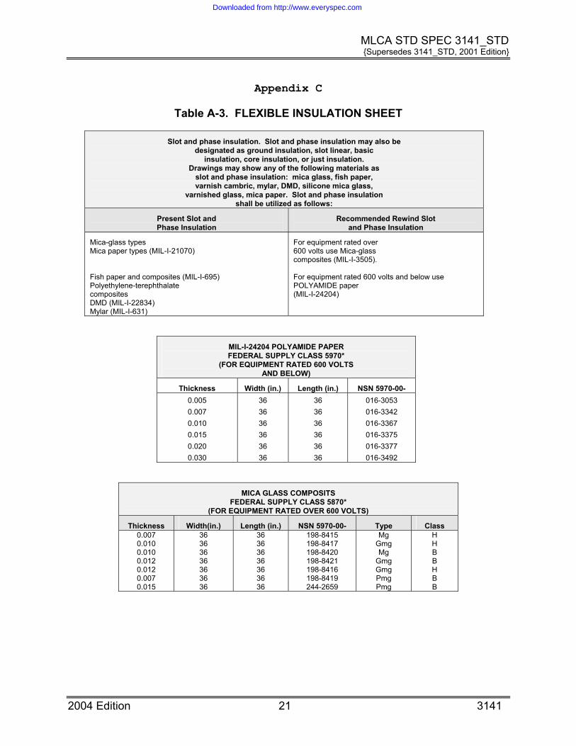
Table A-3. FLEXIBLE INSULATION SHEET
Slot and phase insulation. Slot and phase insulation may also be designated as ground insulation, slot linear, basic
insulation, core insulation, or just insulation. Drawings may show any of the following materials as
slot and phase insulation: mica glass, fish paper, varnish cambric, mylar, DMD, silicone mica glass,
varnished glass, mica paper. Slot and phase insulation shall be utilized as follows:
Present Slot and Phase Insulation
Recommended Rewind Slot and Phase Insulation
Mica-glass types Mica paper types (MIL-I-21070) Fish paper and composites (MIL-I-695) Polyethylene-terephthalate composites DMD (MIL-I-22834) Mylar (MIL-I-631)
For equipment rated over 600 volts use Mica-glass composites (MIL-I-3505). For equipment rated 600 volts and below use POLYAMIDE paper (MIL-I-24204)
MIL-I-24204 POLYAMIDE PAPER FEDERAL SUPPLY CLASS 5970*
(FOR EQUIPMENT RATED 600 VOLTS AND BELOW)
Thickness Width (in.) Length (in.) NSN 5970-00- 0.005 0.007 0.010 0.015 0.020 0.030
36 36 36 36 36 36
36 36 36 36 36 36
016-3053 016-3342 016-3367 016-3375 016-3377 016-3492
MICA GLASS COMPOSITS FEDERAL SUPPLY CLASS 5870*
(FOR EQUIPMENT RATED OVER 600 VOLTS)
Thickness Width(in.) Length (in.) NSN 5970-00- Type Class 0.007 0.010 0.010 0.012 0.012 0.007 0.015
36 36 36 36 36 36 36
36 36 36 36 36 36 36
198-8415 198-8417 198-8420 198-8421 198-8416 198-8419 244-2659
Mg Gmg Mg
Gmg Gmg Pmg Pmg
H H B B H B B
2004 Edition 21 3141
Downloaded from http://www.everyspec.com
MLCA STD SPEC 3141_STD {Supersedes 3141_STD, 2001 Edition}
Appendix D
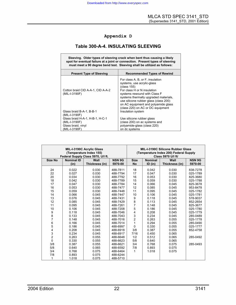
Table 300-A-4. INSULATING SLEEVING
Sleeving. Older types of sleeving crack when bent thus causing a likely spot for eventual failure at a joint or connection. Present types of sleeving
must meet a 90 degree bend test. Sleeving shall be utilized as follows:
Present Type of Sleeving Recommended Types of Rewind
Cotton braid CID A-A-1, CID A-A-2 (MIL-I-3190F) Glass braid B-A-1, B-B-1 (MIL-I-3190F) Glass braid H-A-1, H-B-1, H-C-1 (MIL-I-3190F) Glass braid, vinyl (MIL-I-3190F)
For class A, B, or F, insulation systems, use acrylic-glass (class 155) For class H or N insulation systems rewound with Class F systems thermally upgraded materials, use silicone rubber glass (class 200) on AC equipment and polyamide glass (class 220) on AC or DC equipment Insulation system Use silicone rubber glass (class 200) on ac systems and polyamide-glass (class 220) on dc systems
MIL-I-3190C Acrylic Glass (Temperature Index 155)
Federal Supply Class 5970, U/I ft.
MIL-I-3190C Silicone Rubber Glass (Temperature Index 200) Federal Supply
Class 5970 U/I ft/ Size No Nominal ID
(in) Wall
Thickness (in) NSN 9G 5970-00
Size No
Nominal ID (in)
Wall Thickness (in)
NSN 9G 5970-00
24 22 20 18 17 16 15 14 13 12 11 10 9 8 7 6 5 4 3 2 0
3/8 5/8 3/4 7/8 1
0.022 0.027 0.034 0.042 0.047 0.053 0.059 0.066 0.076 0.085 0.095 0.106 0.118 0.133 0.148 0.166 0.186 0.208 0.234 0.263 0.330 0.387 0.640 0.768 0.893 1.018
0.030 0.030 0.030 0.030 0.030 0.030 0.030 0.045 0.045 0.045 0.045 0.045 0.045 0.045 0.045 0.045 0.045 0.045 0.045 0.055 0.055 0.055 0.065 0.075 0.075 0.075
488-7811 488-7794 488-7792 488-7789 488-7784 488-7477 488-7448 488-7447 488-7431 488-7429 488-7261 488-7208 488-7046 488-7043 488-7016 488-7014 488-6997 488-6918 488-6917 488-6648 488-6623 488-6621 488-6592 488-6464 488-6244 488-5710
18 17 16 15 14 12 11 10 9 8 7 5 4 3 2 1 0
3/8 7/16 1/2 5/8 3/4 7/8 1
0.042 0.047 0.053 0.059 0.066 0.085 0.095 0.106 0.118 0.113 0.148 0.186 0.208 0.234 0.263 0.294 0.330 0.387 0.450 0.512 0.640 0.768 0.893 1.018
0.030 0.030 0.030 0.030 0.045 0.045 0.045 0.045 0.045 0.045 0.045 0.045 0.045 0.045 0.055 0.055 0.055 0.055 0.065 0.065 0.065 0.075 0.075 0.075
838-7278 025-1789 825-3680 025-1788 825-3678 953-8478 025-1782 025-1781 578-9037 852-2654 825-3677 025-1780 025-1779 285-0489 025-1778 285-0490 025-1777 852-4758
285-0492
285-0493
2004 Edition 22 3141
Downloaded from http://www.everyspec.com

MLCA STD SPEC 3141_STD {Supersedes 3141_STD, 2001 Edition}
Table A-4. INSULATING SLEEVING (CONTINUED)
MIL-I-3190F Polyamide Glass (Temperature Index 220)
Federal Supply Class 5970, U/I ft.
Size No. Nominal ID
(in)
Wall Thickness (in)
NSN 5970-00-
16
14
12
10
8
6
2
0
0.053
0.066
0.085
0.102
0.133
0.166
0.263
0.330
0.030
0.030
0.045
0.022
0.045
0.045
0.055
0.055
488-5091
488-5087
488-5082
488-4991
488-4942
488-4883
488-4660
2004 Edition 23 3141
Downloaded from http://www.everyspec.com

MLCA STD SPEC 3141_STD {Supersedes 3141_STD, 2001 Edition}
Appendix E
Table A-5. LAMINATED UNSULATION SHEET (U/I LB)
MIL-I-24768/1 Glass Melamine, Type GME (Temp., Index 130)1
Thickness (in) NSN 5970-00-
0.031 0.062
0.125
0.250
912-1907 905-8336
912-1908
912-1909
Glass Polyester, Type SG 200 (Temp., Index 200)2
0.031 0.064
0.094
0.125
0.250
N/A
NOTES: 1. Suitable for class 155°C applications for slot wedges and coil separators 2. Available from the Glastic Company, 4321 Glenridge Road, Cleveland Ohio 44121
2004 Edition 24 3141
Downloaded from http://www.everyspec.com

MLCA STD SPEC 3141_STD {Supersedes 3141_STD, 2001 Edition}
Appendix F
Table A-6. LACING AND TYING TAPE
Lacing and tying cords and tapes have been made from twisted cords, braided cords and braided flat tapes using cotton, flax or glass yarns. Finishes applied
to these materials to improve knot strength and application have been waxes, synthetic rubbers and
resin coatings. Lacing and tying tape shall be utilized as follows:
Present Types Recommended Type
Glass cord (MIL-Y-1140) Cotton Cord (MIL-T-713 (Also flax, hemp or resin
Polyamide, Type V Finish A (natural) per CID A-A-52083
MIL-T-43435A. POLYAMIDE TAPE - HEAT RESISTANT, FLAT BRAIDS, FEDERAL SUPPLY
CLASS 5970 (Cont'd)
NSN 5970-00-001
Size
Width
(in)
Thickness
(in)
Breaking Strength
(lb)
U/I
Yds per Spool
9356 1 0.200 0.016 85 250
9357 2 0.110 0.014 50 250
9358 3 0.090 0.012 35 500
9359 4 0.055 0.01 25 500
2004 Edition 25 3141
Downloaded from http://www.everyspec.com

MLCA STD SPEC 3141_STD {Supersedes 3141_STD, 2001 Edition}
Appendix G
Table A-7. INSULATION TAPE (U/I ROLL)
MIL-Y-1140 TAPE, TEXTILE, GLASS, UNTREATED, ECC-B
FEDERAL SUPPLY CLASS 8315
NSN 8315-00 Width (in) Thickness (in) Break Strength (lb)
290-8265
290-8256
290-8266
290-8260
290-8264
290-8259
290-8254
290-8258
290-8278
3/8
3/8
1/2
1/2
3/4
3/4
3/4
1
1
0.003
0.007
0.003
0.005
0.003
0.005
0.007
0.005
0.007
45
115
60
135
95
225
225
310
240
MIL-I-15126 TAPE, ADHESIVE, GLASS BACKING
FEDERAL SUPPLY CLASS 5970 (TEMP. INDEX 155)
NSN 5970-00 Width (in) Thickness (in) Dielectric Strength (volts)
543-1154
686-9151
1/2
1
0.007
Any
1000
Any
MIL-I-19166 TAPE, ADHESIVE, GLASS BACKING
FEDERAL SUPPLY CLASS 5970 (TEMP. INDEX 200)
NSN 5970-00 Width (in) Thickness (in) Dielectric Strength (volts)
709-0045
933-1406
650-5345
0.625
0.250
0.500
0.007
0.007
0.012
2000
2000
4000
MIL-I-24391 TAPE, ADHESIVE, PLASTIC BACKING, BLACK
FEDERAL SUPPLY CLASS 5970 (TEMP. INDEX 105)
NSN-5970-00- Width (in) Thickness (in)
419-3164
419-4291
419-4290
1.000
0.750
0.500
0.0085
0.0085
0.0080
2004 Edition 26 3141
Downloaded from http://www.everyspec.com
MLCA STD SPEC 3141_STD {Supersedes 3141_STD, 2001 Edition}
Appendix H
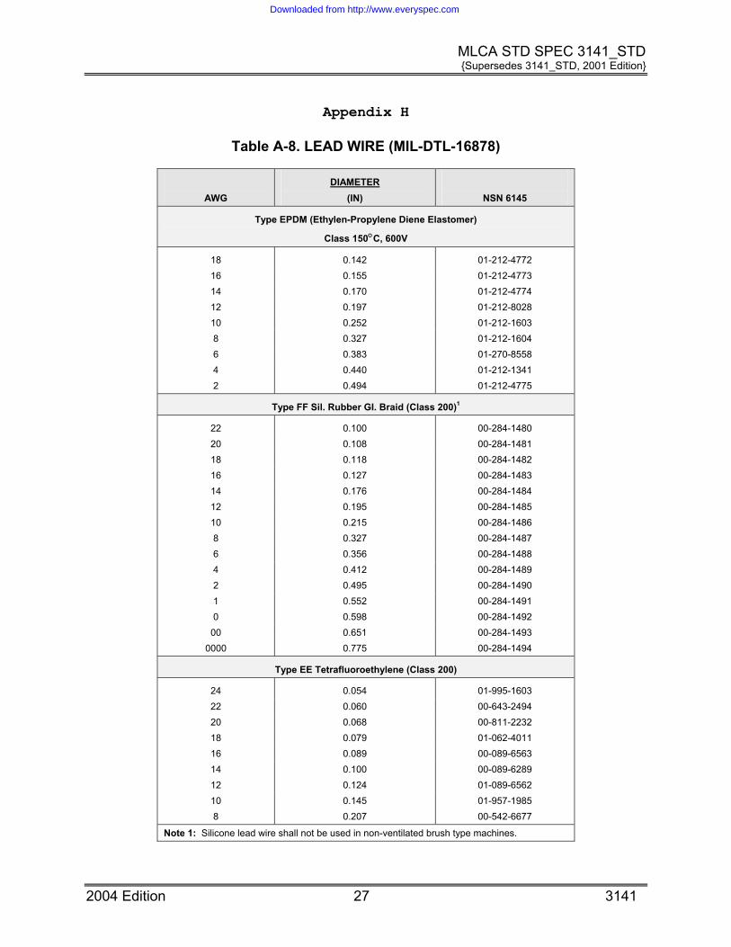
Table A-8. LEAD WIRE (MIL-DTL-16878)
AWG
DIAMETER (IN)
NSN 6145
Type EPDM (Ethylen-Propylene Diene Elastomer)
Class 150°C, 600V
18 0.142 01-212-4772 16 0.155 01-212-4773 14 0.170 01-212-4774 12 0.197 01-212-8028 10 0.252 01-212-1603 8 0.327 01-212-1604 6 0.383 01-270-8558 4 0.440 01-212-1341 2 0.494 01-212-4775
Type FF Sil. Rubber GI. Braid (Class 200)1
22 0.100 00-284-1480 20 0.108 00-284-1481 18 0.118 00-284-1482 16 0.127 00-284-1483 14 0.176 00-284-1484 12 0.195 00-284-1485 10 0.215 00-284-1486 8 0.327 00-284-1487 6 0.356 00-284-1488 4 0.412 00-284-1489 2 0.495 00-284-1490 1 0.552 00-284-1491 0 0.598 00-284-1492
00 0.651 00-284-1493 0000 0.775 00-284-1494
Type EE Tetrafluoroethylene (Class 200)
24 0.054 01-995-1603 22 0.060 00-643-2494 20 0.068 00-811-2232 18 0.079 01-062-4011 16 0.089 00-089-6563 14 0.100 00-089-6289 12 0.124 01-089-6562 10 0.145 01-957-1985 8 0.207 00-542-6677
Note 1: Silicone lead wire shall not be used in non-ventilated brush type machines.
2004 Edition 27 3141
Downloaded from http://www.everyspec.com

MLCA STD SPEC 3141_STD {Supersedes 3141_STD, 2001 Edition}
Appendix I
Table A-9. VARNISH INSULATION
MIL-I-24092 CLEAR, BAKING, SOLVENT TYPES
Class NSN-5970-01- U/I Thinner
155 931-2413 1 gal can Xylene 155 931-1170 5 gal can Xylene 200 931-2414 5 gal can Xylene 200 548-7211 1 gal can Xylene
MIL-I-24092 CLEAR, AIR-DRYING, SOLVENT TYPES
Grade NSN-5970-01- U/I Thinner Mfr. Brand No.
CA 190-5473 1 gal can Mineral spirits AC 41 Dolph CA 252-7481 1 gal can Mineral spirits AC 43 Dolph
MIL-I-24092 VARNISH, CLEAR, AIR-DRYING TYPE
Type NSN 5970-01- U/I Mfr. Part No.
CA 078-5636 1 gal Sterling U-122
RED INSULATING VARNISH – AIR DRY1
Type U/I NSN Mfr. Brand No.
Air dry – moisture, oil, and salt water resistant
16 oz spray can 5900-00-076-8988 ER-41 RED
Note: 1. For SWBD buswork, frame coating, etc
SOLVENTLESS BAKING VAR
Composition Mfr. Brand No. Mfr.
POLYESTER Esterlite 605 Epoxylite
POLYESTER Isolite 826M Schenectady Chemical
2004 Edition 28 3141
Downloaded from http://www.everyspec.com

MLCA STD SPEC 3141_STD {Supersedes 3141_STD, 2001 Edition}
2004 Edition 29 3141
Appendix J
Table A-10. SLOT WEDGE INSULATION FORMES POLYAMIDE PAPER (U SHAPE)
FEDERAL SUPPLY CLASS 5970; U/I-FEET; FSCM (Mfgr code) – 87952
Shape Width (in) Thickness (in) NSN 5970-00- Mfgr Type
Curve 5/32 11/64 004-4491 NHT 70-30
Curve 7/32 3/16 004-4490 NHT 86-30
Curve 1/4 7/32 004-4489 NHT 99-30
Curve 5/16 1/4 004-4488 NHT 117-30
Curve 3/8 5/16 004-4487 NHT 144-30
Square 5/32 7/32 004-4486 NHT 30-10-14
Square 1/4 11/64 004-4492 NHT 30-16-11
Square 23/64 1/4 004-4493 NHT 30-23-16
Downloaded from http://www.everyspec.com