development of robotic hand
TRANSCRIPT

Development of Robotic Hand
Mashetty Nikhil
A Dissertation Submitted to
Indian Institute of Technology Hyderabad
In Partial Fulfillment of the Requirements for
The Degree of Master of Technology
Department of Mechanical and Aerospace Engineering
July, 2015


Acknowledgements
I have a dream of becoming an IITian and now it’s came true. I express my sincere gratitude to my advisor Dr. R. Prasanth Kumar for making my dream to happen and for encouraging me during
my Master’s thesis work. I am always inspired with his work throughout my stay at IIT Hyderabad.
He taught me how to be dedicative to our work and his patience towards my mistakes encouraged
me to learn a lot. I am thankful to him for having believe on my ability to do work.
I would like to thank Prof. U.B Desai, Director, IIT Hyderabad and Prof. Vinayak Eswaran,
HoD, Department of Mechanical and Aerospace Engineering, IIT Hyderabad for their direct and
indirect support to my thesis.
I would like to thank my examiners Dr. Chandrika Prakash Vyasarayani, Dr. Viswanath
Chinthapenta, Dr. B Venkatesham and my external examiner Dr. S Sireesh for their valuable
suggestions and appreciations for all the reviews.
I would like to thank the IIT Hyderabad Central Workshop and Manufacturing Lab staff for
helping me in all fabrication works. And my sincere thanks to Satyanarana sir and M A
Somashekar for helping me at any time, when I request them for fabrication works.
I would like to thank my parents Dhana Laxmi and Haribabu, sister Neelima for their support
and encouragement throughout my life. Thanks to my grandmother Anasuya for always caring and
wants me to be the best.
I would like to thank my lab mates Lokesh, Janardhan, Santhosh kumar and Vikram for their
contribution to my work.
Finally, special thanks to my best friends S.Shiva Kumar, Giridhar, Deepak, Ratikant, Sivanand,
Lingeshwar, Srinivas, Jyothi, K.Naresh Reddy and my roomie Pratap Rao Patel for making me
emotionally strong with their constant support. I thanks to my friends Ranjith kumar, Venkatesh,
U. Sai Kumar, Prasuna, Pavan Kumar, Jaya Naidu, Srikanth, Uday kumar whom, I always
remember throughout my life for helping me to be a best person through their friendship.
(iv)
Dedicated to
My Parents and All my Teachers

Abstract
Humanoid robots have become more important in the military applications, space
exploration missions and hazardous environments like mining. The purpose of a humanoid robot
is to walk, jump, run, grasp the objects, manipulate the objects etc., Robotic hand plays an
important role for a humanoid robot. This thesis focuses on the development of robotic hand for
the humanoid robot. It includes (a) Development of robotic hand (only four fingers) with tendons
and servo motors, (b) Development of robotic hand only with the servo motors for practicing the
human grasps and the heavy wrap has been demonstrated, (c) Design of robotic Arm and the
experimental setup to conduct experiments for improvising the robot efficiency.
Robotic hand is analyzed by considering each finger as each module. These fingers has 3
degrees of freedom, which is actuated by 3 servo motors and complete hand has 4 fingers with 12
degrees of freedom. Kinematic analysis is done by calculating Denavit-Hartenberg (DH)
parameters.
Fingers have been fabricated by the Fused Deposition Technique with the plastic material.
These fingers have in-built pulley and the provisions for the tendons. It has 12 degrees of freedom
which is done by 12 servo motors. These servo motors are controlled by Arduino Nano board. Fish
wires have been used as tendons which act like a human muscles to drive the finger joints. This
can also be used a Rehabilitation purpose.
Another version of robotic hand has been developed by using only the servo motors, which
are commercially available low cost motors so as to reduce the cost of the robot. This robotic hand
is used to perform the human grasps. Heavy wrap, which is a type of human grasp has been
demonstrated with this robot.
Robotic arms has been designed to mount on a work table, which helps in conducting the
experiments with the robotic hand. This even helps to improve the efficiency of the robot. Each
robotic arm has 5 degrees of freedom and a total of 10 degrees of freedom for two arms.
(vi)

Contents
Declaration…………………………………………………………………………………….. (ii)
Approval sheet………………………………………………………………………………… (iii)
Acknowledgements………………………………………………............................................. (iv)
Abstract………………………………………………………………………………………... (vi)
Contents………………………………………………………………………... (vii)
List of figures…………………………………………………………………… (ix)
List of tables...…………………………………………………………………... (x)
1. Introduction and Literature Review 1
1.1 Introduction……………………………………………………………… 1
1.2 Motivation……………………………………………………………….. 1
1.3 Literature Review……………………………………………................... 2
1.4 Objective and Scope…………………………………………................... 3
1.5Problem statement………………………………………………………... 4
2. Modeling 5
2.1 Kinematic Analysis of Robotic Hand…………………………................... 5
2.2 Fabrication………………………………………………………………… 6
3. Calculations 10
4. Classification of Human Grasp 12
4.1 Kinematic Analysis of Heavy wrap………………………………………. 12
4.2 Demonstration of Heavy Wrap…………………………………………… 14
5. Design of Robotic Arm 15
5.1 Kinematic analysis of Robotic Arm………………………………………. 16
(vii)

5.1 (a) Forward Kinematic analysis…………………………….................... 16
5.1 (b) Inverse kinematics of Robotic Arm………………………………… 18
5.2 Experimental Setup……………………………………………………….. 19
6. Conclusions and Recommendations for Future work 20
6.1 Conclusions……………………………………………………………... 20
6.2 Recommendations for future work…………………………………….... 20
7. References 21
(viii)
List of figures
Fig. 1 (i) Belgrade/USC [1], (ii) Reading University – CybHand [2] ,(iii) JPL Hand [4] ,
(iv) UTAH Hand [3]…………………………………………………………………………………... 2
Fig. 2 DLR-HIT Hand [9] ……………………………………………………………………………. 3
Fig. 3 Links and the coordinate system according to DH parameter rule ……………………………. 6
Fig. 4 CAD models of the finger and palm. (a) Distal end, (b) proximal end and middle part,
(c) Base for fingers (palm) and (d) motor casing……………………………………………………... 7
Fig. 5 Micro Servo……………………………………………………………………………………. 8
Fig. 6 Images of the robotic hand…………………………………………………………………...... 8
Fig. 7 (a) Representation of r2, (b) Representation of finger joint with the radius of the pulley……. 11
Fig. 8 Actuation of Distal link……………………………………………………………………….. 11
Fig. 9 Actuation of Proximal link……………………………………………………………………. 11
Fig. 10 Tangents passing through the external point……………………………………………….... 13
Fig. 11 Point of contacts of the finger……………………………………………………………….. 13
Fig. 12 Demonstration of heavy wrap……………………………………………………………...... 14
Fig. 13 3-D Model of robotic hand………………………………………………………………...... 15
Fig. 14 Dynamixel Pro H54-200 actuator…………………………………………………………... 16
Fig. 15 Coordinate system for robotic arm according to DH Parameter rule……………………..... 17
Fig. 16 Representation of locus of the elbow joint…………………………………………………. 18
Fig. 17 Image Courtesy: IITH workshop, Fabrication of experimental setup……………………… 19
Fig. 18 Experimental setup of robotic arm…………………………………………………………. 19
(ix)

List of tables
Table 1: DH parameters …………………………………………………………………………………… 5
Table 2: Properties of ABS plus plastic …………………………………………………………………… 6
Table 3: Specifications of Servo motor …………………………………………………………………… 8
Table 4: Specifications of robotic hand …………………………………………………………………… 9
Table 5: Specifications of actuators ……………………………………………………………………… 16
Table 6: DH parameters of robotic arm ………………………………………………………………….. 17
(x)
Chapter 1
Introduction and Literature Review
1.1 Introduction
In order to build a humanoid robot, building a robotic hand plays an important role. Its role
is to grasp and manipulate the objects without damaging from one place to another in any intrinsic
environments. This also acts as an end effecter to any manipulator. Robotic hand is an imitation
of human hand and it should consists same DOF as of human hand. Difficulty in the problem is to
perform all the grasps like human, manipulate the things with a light weight, compact size robotic
hand. It should detect, sense and determine the objects to manipulate and act intelligently. We
designed the robotic hand which is driven by cables actuated by servo motors. These cables are
similar to the tendons in the human hand which are actuated by elongation and contraction of
muscles.
During the past few years, the pace of research on artificial multi-fingered hands for robot
manipulators has significantly increased [10-23]. Each finger of multi-fingered robot hands can be
considered as an independent manipulator; thus, operation of a hand requires coordinated motion
of several separate small manipulators. When holding an object with a multi-fingered hand, the
grasp must satisfy a number of conditions, such as static equilibrium, no slippage, and the ability
of resisting disturbance in all directions.
Now a days, robotic hand is also using as rehabilitation medicine.
1.2 Motivation
It is necessary to reduce the human damage during the wars or working in any hazardous
environments like Mining, Nuclear plants or in Space applications. So, to replace the human
interaction, researchers have started working on the development of human like machine called
humanoid robot. The purpose of this humanoid robot is to walk, jump, run, process and grasp the
objects, friendly interaction with the people etc., like human. One of the important task in
developing the humanoid is the robotic hand. It has to process the things and grasp the objects
without damaging the objects. Difficulty in the development of robotic hand is to perform all the
grasps like human, manipulate the things with a light weight, compact size robotic hand. So, it is
necessary to study the kinematics and dynamics of human hand, control systems, actuators and
sensors in order to achieve a compact size robotic hand.
1
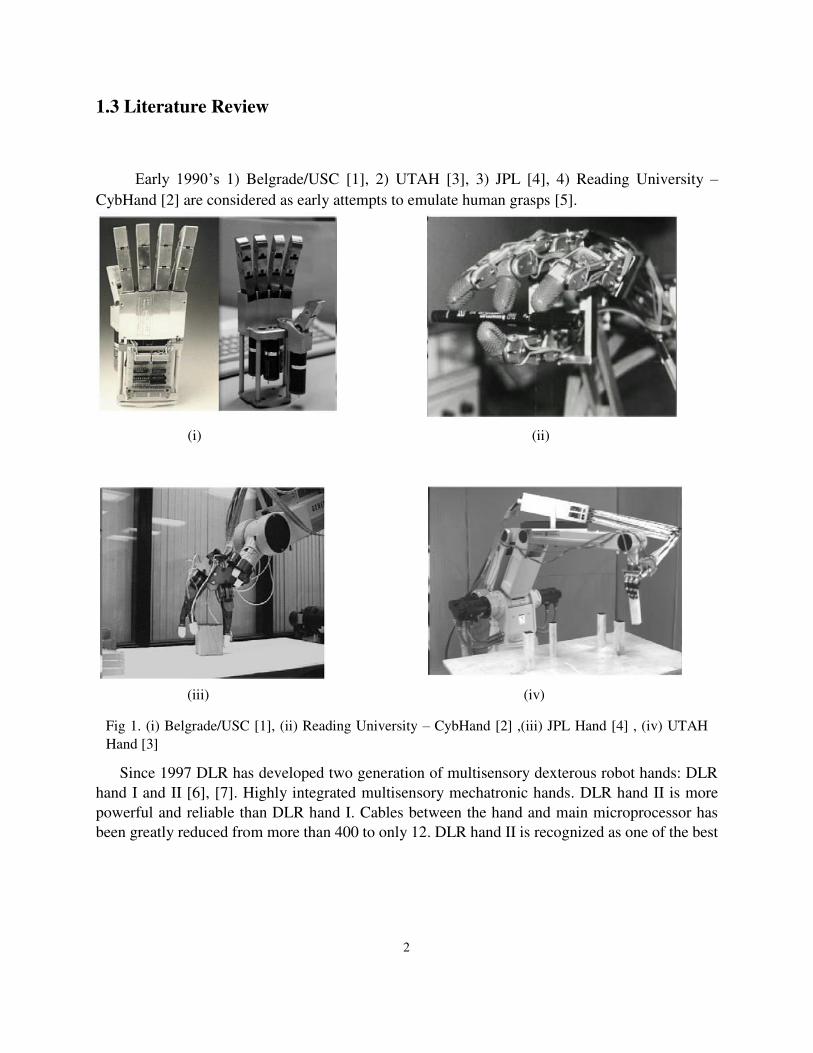
1.3 Literature Review
Early 1990’s 1) Belgrade/USC [1], 2) UTAH [3], 3) JPL [4], 4) Reading University –
CybHand [2] are considered as early attempts to emulate human grasps [5].
(i) (ii)
(iii) (iv)
Since 1997 DLR has developed two generation of multisensory dexterous robot hands: DLR
hand I and II [6], [7]. Highly integrated multisensory mechatronic hands. DLR hand II is more
powerful and reliable than DLR hand I. Cables between the hand and main microprocessor has
been greatly reduced from more than 400 to only 12. DLR hand II is recognized as one of the best
Fig 1. (i) Belgrade/USC [1], (ii) Reading University – CybHand [2] ,(iii) JPL Hand [4] , (iv) UTAH
Hand [3]
2
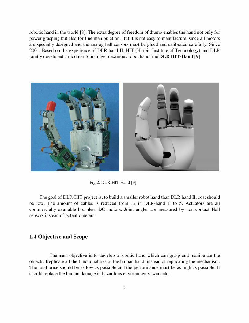
robotic hand in the world [8]. The extra degree of freedom of thumb enables the hand not only for
power grasping but also for fine manipulation. But it is not easy to manufacture, since all motors
are specially designed and the analog hall sensors must be glued and calibrated carefully. Since
2001, Based on the experience of DLR hand II, HIT (Harbin Institute of Technology) and DLR
jointly developed a modular four-finger dexterous robot hand: the DLR HIT-Hand [9]
The goal of DLR-HIT project is, to build a smaller robot hand than DLR hand II, cost should
be low. The amount of cables is reduced from 12 in DLR-hand II to 5. Actuators are all
commercially available brushless DC motors. Joint angles are measured by non-contact Hall
sensors instead of potentiometers.
1.4 Objective and Scope
The main objective is to develop a robotic hand which can grasp and manipulate the
objects. Replicate all the functionalities of the human hand, instead of replicating the mechanism.
The total price should be as low as possible and the performance must be as high as possible. It
should replace the human damage in hazardous environments, wars etc.
Fig 2. DLR-HIT Hand [9]
3
1.5 Problem Statement
Is to develop the robotic hand for a humanoid at a low cost and high performance. The required
finger parts are to be fabricated by FDM and the actuation is done by the cheaply available servo
motors. These servo motors are controlled by Arduino Nano board. Each finger has 3 Dof’s and
the hand has 4 fingers.
Developed robot should perform all the grasps as of human.
4
Chapter 2
Modeling
2.1 Kinematic analysis of robotic hand
In order to analyze the kinematic and dynamic behavior of a human finger, we assign the
coordinate system to every joint according to the DH parameter rules. As shown in the fig. 3, three
coordinate systems are assigned to each joint and one at the finger tip. The DH parameters of the
finger under consideration are defined in the following table,
θ α d a (mm)
θ1 0 0 25
θ2 0 0 25
θ3 0 0 15
Where,
θ is angle of rotation about the joint axis
α is angle about common normal, from old z axis to new z-axis
d is offset along previous z to the common normal
a is length of the common normal (link length)
Table 1: DH parameters
5

Fig 3. Links and the coordinate system according to DH parameter rule
2.2. Fabrication
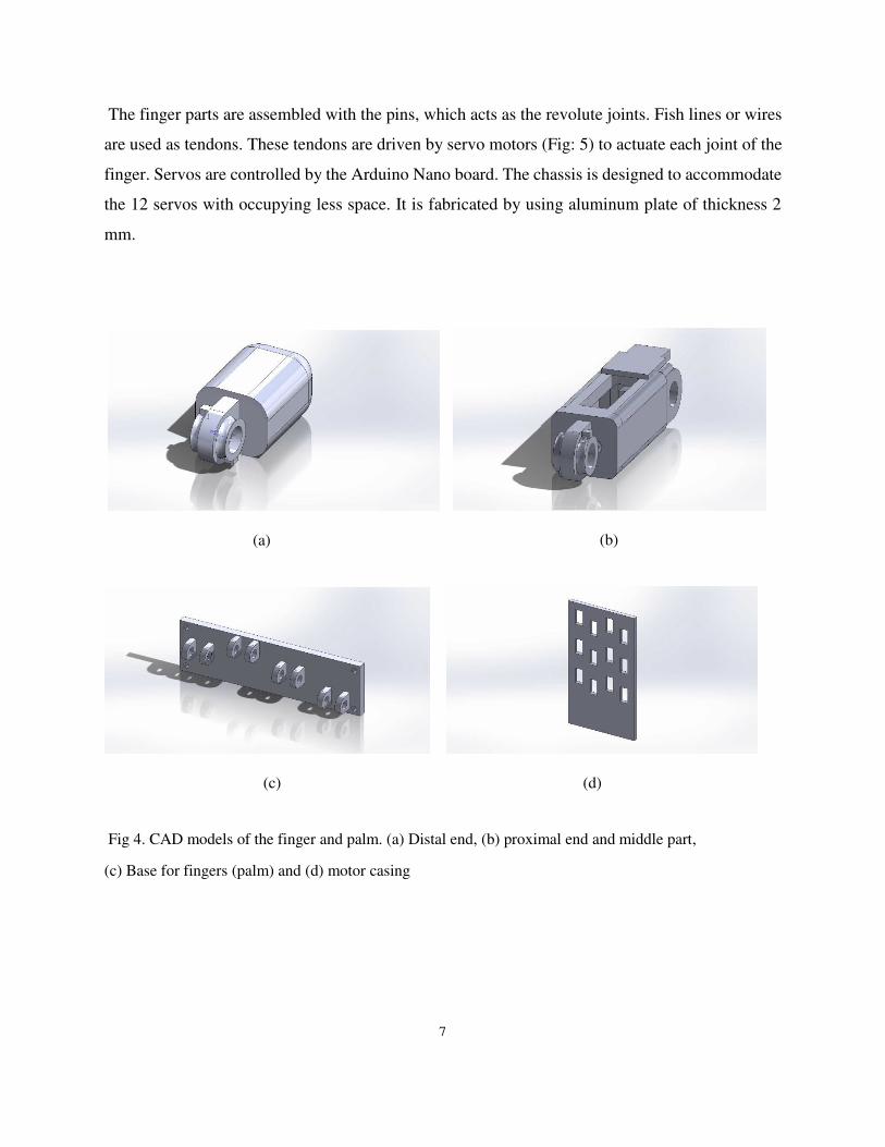
Finger parts are fabricated using the FDM (Fused deposition modelling) process. This is a
rapid prototyping process in which the given shape of a CAD model is laid layer by layer. The
finger CAD models are represented in the fig. 4. These models are designed such that they should
accommodate the tendons over the pulleys at the joint. The pulley is in-built into the model. By
using a proper technique the tendons are lined into the finger parts which goes from the pulleys to
the motor. The material used in the FDM process is ABS plus plastic and whose properties are
given in the table 2 [24]. ABS means Acrylonitrile butadiene styrene.
Property ABSPlus
Tensile strength 44 MPa
Elongation at break 24.3%
Flexural strength 68.9 MPa
Flexural modulus 2,198 MPa
Specific gravity 1.04
Table 2: Properties of ABS plus plastic
6
The finger parts are assembled with the pins, which acts as the revolute joints. Fish lines or wires
are used as tendons. These tendons are driven by servo motors (Fig: 5) to actuate each joint of the
finger. Servos are controlled by the Arduino Nano board. The chassis is designed to accommodate
the 12 servos with occupying less space. It is fabricated by using aluminum plate of thickness 2
mm.
Fig 4. CAD models of the finger and palm. (a) Distal end, (b) proximal end and middle part,
(c) Base for fingers (palm) and (d) motor casing
(a)
(d) (c)
(b)
7

Specifications of the motor [25]:
Dimensions Length: 23.1 mm
Width: 12.2 mm
Height: 29.0 mm
Weight 9 gms
Torque at 4.8 V :1.80 kg-cm
Speed at 4.8 V : 0.12sec /60 deg (no load)
Fig 6. Images of the robotic hand
Fig 5. Micro Servo
Table 3: Specifications of Servo motor
8

Specifications of robotic hand:
Total weight 320 gms including controller (arduino nano)
Dimensions It can fit in a rectangular box of 28 cm * 10
cm
Number of fingers 4
Total Dof 12
Number of actuators 12
Controller Arduino Nano
Table 4: Specifications of robotic hand
9
Chapter 3
Calculations
While analyzing the kinematics and dynamics of the finger module using multi body
dynamics, all the calculations are with respect to the joint coordinate system. So it is necessary to
know the relation between the joint torque and the torque applied by the motor, similarly in case
of joint displacement and the motor rotation. Let τ1 be the torque at the finger joint and τ2 be the
torque at the motor, then due to design considerations,
�� = ��
Where,
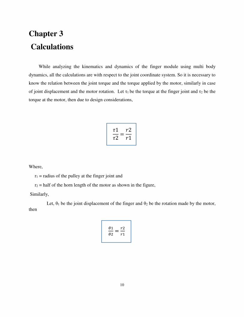
r1 = radius of the pulley at the finger joint and
r2 = half of the horn length of the motor as shown in the figure,
Similarly,
Let, θ1 be the joint displacement of the finger and θ2 be the rotation made by the motor,
then
�� = ��
10
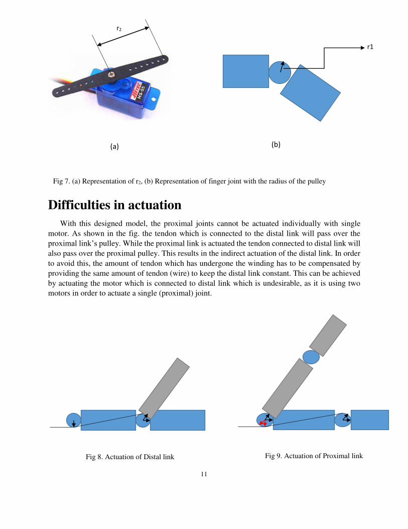
Difficulties in actuation
With this designed model, the proximal joints cannot be actuated individually with single
motor. As shown in the fig. the tendon which is connected to the distal link will pass over the
proximal link’s pulley. While the proximal link is actuated the tendon connected to distal link will
also pass over the proximal pulley. This results in the indirect actuation of the distal link. In order
to avoid this, the amount of tendon which has undergone the winding has to be compensated by
providing the same amount of tendon (wire) to keep the distal link constant. This can be achieved
by actuating the motor which is connected to distal link which is undesirable, as it is using two
motors in order to actuate a single (proximal) joint.
r1
Fig 7. (a) Representation of r2, (b) Representation of finger joint with the radius of the pulley
r2
(a) (b)
Fig 9. Actuation of Proximal link Fig 8. Actuation of Distal link
11
Chapter 4
Classification of Human Grasp
Human grasp can be classified as follows [26]:
Power Grasp
Non-Prehensile
Prehensile
Precision Grasp
Circular
Prismatic
Heavy wrap is a type of Power Grasp, which is used to grasp the cylindrical objects. It can be
used for both larger and smaller diameter objects and all the fingers will wrap over circumference
of the object.
4.1 Kinematic Analysis of Heavy wrap
Heavy wrap is to hold both large and small cylindrical objects. Fingers of the hand get in
contact with the object at the point of contact or point of tangency to the object. In order to calculate
the point of contact of the fingers, robot should have a prior knowledge of the object (diameter and
length).
Point of contact is calculated by considering a line passing through the external point and is
a tangent to the circle. As shown in the fig. 10, there exists two tangents passing through a single
external point. So there exists two different wraps for a given cylindrical object and it is necessary
to decide which wrap can be feasible for given object and position of the object.
In order to calculate the point of contact, first we fix the coordinate system at the joint between
palm and the finger. So, to calculate the first point of contact we consider the origin P (fig. 11), as
the first external point and the point of tangency to the object is the first point of contact. Similarly
for the second point of contact, the external point will be the tip of the first link and the point of
tangency through the tip of the link is the second point of contact. Same procedure is repeated in
order calculate the other point of contacts as shown in the fig 11.
12

P
C
r
P1
P
C
r
P1
P2
P3
Fig 10. Tangents passing through the external point
Fig 11. Point of Contacts of the Finger
13

4.2 Demonstration of Heavy Wrap
Robotic hand with only servo motors have been developed to perform the human grasps.
It doesn’t require any tendons and each joint is actuated by each servo motor. The motor is aligned in such a way that the motor axis and the joint axis will coincide.
Servo motors are connected with plastic casings which are fabricated by FDM process.
Using this robotic hand, heavy wrap is demonstrated. As shown in the fig 12, robotic hand is
grasping a 500gms water bottle and holds it firmly. In order to have a proper grip, a rubber tube is
mounted over the bottle.
Fig 12. Demonstration of Heavy wrap
14
5. Design of Robotic Arm
Robotic arm helps in transferring the objects from one place to another and increases the
stability of humanoid robot while walking and running. Robotic arm is designed by considering 5
degrees of freedom to each arm and it should be mounted on a work table to perform experiments
with the robotic hand. In order to practice different grasps and to increase the performance of the
robotic hand this experimental setup has been developed. Fig. 13, represents the 3-D model of the
robotic arm with the stand. Stand helps in mounting the robotic arms over the work table and
provides stability to the setup.
Each arm has 5 Degrees of freedom with a total of 10 Dof’s for two arms. These are actuated by 10 Dynamixel Pro H54-200 servo motors as shown in the fig. 14 and even acts as the
links to the arm. All the motor casings have been fabricated using Aluminum in order to have light
weight and low cost with high strength. Dynamixel Pro is an integrated actuator composed of a
gear reduction system, controller, driver and network for constructing modular robots. It has a
maximum resolution of 5, 02,000 steps per one full rotation.
Fig 13. 3-D Model of robotic hand
15
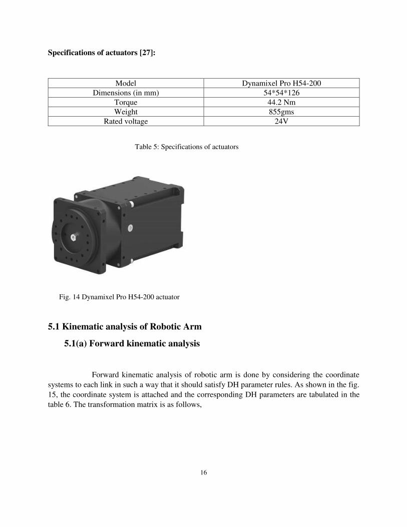
Specifications of actuators [27]:
Model Dynamixel Pro H54-200
Dimensions (in mm) 54*54*126
Torque 44.2 Nm
Weight 855gms
Rated voltage 24V
5.1 Kinematic analysis of Robotic Arm
5.1(a) Forward kinematic analysis
Forward kinematic analysis of robotic arm is done by considering the coordinate
systems to each link in such a way that it should satisfy DH parameter rules. As shown in the fig.
15, the coordinate system is attached and the corresponding DH parameters are tabulated in the
table 6. The transformation matrix is as follows,
Fig. 14 Dynamixel Pro H54-200 actuator
Table 5: Specifications of actuators
16
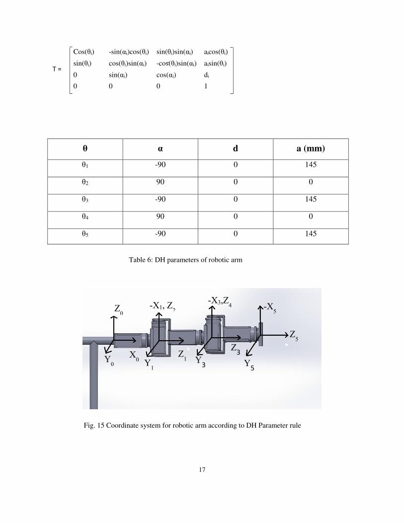
Cos(θi) -sin(αi)cos(θi) sin(θi)sin(αi) aicos(θi)
sin(θi) cos(θi)sin(αi) -cos(θi)sin(αi) aisin(θi)
0 sin(αi) cos(αi) di
0 0 0 1
θ α d a (mm)
θ1 -90 0 145
θ2 90 0 0
θ3 -90 0 145
θ4 90 0 0
θ5 -90 0 145
Z0
X0 Y
0
-X1, Z2
Z1
Y1
-X3,Z4
Z3
Y3
-X5
Z5
Y5
Table 6: DH parameters of robotic arm
Fig. 15 Coordinate system for robotic arm according to DH Parameter rule
17
T =

5.1(b) Inverse kinematics of Robotic Arm
Human arm has 7 degrees of freedom and is analyzed by considering 3 degrees of freedom at
the shoulder, 3 degrees of freedom at the wrist and 1 degree of freedom at the elbow. In order to
analyze the inverse kinematics of the human arm, shoulder is fixed at the origin as shown in fig
16.
Inverse kinematics is the process where we know the position of the end effector or wrist
and we need to find all the joint angles in order to reach the required wrist position. So at the
required wrist position the elbow joint has redundant positions on the circle as shown in the fig.
16. It is necessary to provide the position of the elbow on the circle, this is given by providing the
swivel angle.
Swivel angle (ϕ) is defined as the angle between any reference plane passing through the
shoulder and the wrist and the plane passing through all the three points shoulder, wrist and the
elbow. Following equations are the joint angles θ1, θ2 according to the required wrist and elbow
position. Similarly we can calculate θ3, θ4 can be calculated which is dependent on position of the
wrist.
θ1= ���� �� ,
θ2 = atan − √��2−� 2ez
Here,
(ex,ey,ez) is position of elbow,
lu = length of the upper link
Shoulder
Wrist P
Elbow E φ
Fig. 16 Representation of locus of the elbow joint
18

5.2 Experimental Setup
All the motor holders have been fabricated in the IITH central workshop and
Manufacturing Lab (fig. 17). Experimental setup has been mounted on a working table, where
the experiments are to be carried out (fig. 18). This helps in improvising the performance of
the robotic hand and arm.
Fig. 17 Image Courtesy: IITH workshop, Fabrication of experimental setup
Fig. 18 Experimental setup of robotic arm
19

6. Conclusion and Recommendation for Future work
6.1 Conclusions
Robotic hand with four fingers, which uses Servo motors and Tendon mechanism to
actuate has been developed.
Robotic hand with only servo motors has been developed and demonstrated the Heavy
wrap by using the same.
Robotic arm with 5 Dof of each arm has been mounted on a working table which is used
as an experimental setup for enhancing the performance of the robotic hand and the
grasp ability.
6.2 Recommendation for Future work
The complete hand is to be fabricated using FDM, which can be controlled by the
servo motors and Arduino nano board.
Orientation for the thumb is to be optimized and implemented onto the robotic
hand.
Force, torque, position sensors have to be included into the finger and should be
automated.
It should perform all the grasps similar to the human hand.
Wrist should be included in the robotic arm.
20
7. References
1. W. Jimmy, G. Gini, Robotic hands: design review and proposal of new design process, World
Academy of Science, Engineering and Technology 26 26 (17) (2007) 85–90.
2. E. AlGallaf, A. Allen, K. Warwick, A survey of multi-fingered robot hands: issues and
grasping achievements, Journal of Mechatronics 3 (4) (1993) 465–491.
3. C. Jacobsen, E. Wood, F. Knutti, B. Biggers, The UTAH/M.I.T. dextrous hand: work in
progress, International Journal of Robotics Research 3 (1984) 21–50.
4. M. Matthew, K. Salisbury, Robot Hands and the Mechanics of Manipulation, The MIT Press,
USA, 1985.
5. Ebrahim Mattar, A survey of bio-inspired robotics hands implementation: New directions in
dexterous manipulation, Robotics and Autonomous Systems 61 (2013) 517–544
6. Liu, H. ; DutterfaB, ,1.; Knoch, S.; Meusel, P. ; Hirzinger, G.: A New Control Strategy for
DLR's Multisensory Articulated Hand, Control Systems, VoL 19, No. 2, April 1999, pp. 47-
54.
7. J. Butterfass, M. Grebenstein, H. Liu, "DLR-Hand II: Next generation of a dexterous robot
hand," In Proceedings of the 2001 IEEE International conference on Robotics & Automation.
2001, pp. 109-114
8. Hong Liu, Member, IEEE, Peter Meusel, Gerd Hirzinger, Fellow, IEEE, Minghe Jin, Yiwei
Liu, and Zongwu Xie, “The Modular Multisensory DLR-HIT-Hand: Hardware and Software
Architecture”, IEEE/ASME TRANSACTIONS ON MECHATRONICS, VOL. 13, NO. 4, AUGUST 2008
9. H. Liu a,*, P. Meusel a, N. Seitz a, B. Willberg a, G. Hirzinger a, M.H. Jin b,Y.W. Liu b, R.
Wei b, Z.W. Xie “The modular multisensory DLR-HIT-Hand”, Mechanism and Machine
Theory 42 (2007) 612–625
10. Cole, J. Hauser, S. Sastry, Kinematics and control of a multifingered robot hand with rolling
contact, IEEE Transactions on Automatic Control 3,; (4) (1989) 398-403.
11. Z.X. Li, S. Sastry, Task oriented optimal grasping by multifingered robot hands, IEEE Journal
Robotics and Automation 14 (1988) 32-43.
21
12. Y. Nakamura, K. Nagal, T. Yoshikawa, Dynamics and stability in coordination of multiple
robotic mechanisms, International Journal on Robotics Research 8 (2) (1989) 44 -61.
13. ET. Cheng, D.E. Orin, Efficient algorithm for optimal force distribution-the compact-dual LP
method, IEEE Transactions on Robotics and Automation 6 (1990) 178-187.
14. Z. Li, T.J. Tam, A.K. Bejczy, Dynamic workspace analysis of multiple cooperating robot arms,
IEEE Transactions on Robotics and Automation 7 (5) (1991) 589-596.
15. W.S. Lu, Q.H. Meng, On optimal force distribution of coordinating manipulators, International
Journal on Robotics and Automation 7 (2) (1992) 70-79.
16. Y.D. Shin, M.J. Chung, An optimal force distribution scheme for cooperating multiple robot
manipulators, Robotica 11 (1993) 49-59.
17. D.P. Chevallier, S. Payandeh, On computing the friction forces associated with three-fingered
grasp, International Journal on Robotics Research 13 (2) (1994) 119-126.
18. P.D. Panagiotopoulos, A.M. A1-Fahed, Robot hand grasping and related problem: Optimal
control and identification, International Journal on Robotics Research 13 (2) (1994) 127-136.
19. M.J. Sheridan, S.C. Ahalt, D.E. Orin, Fuzzy control for robotic power grasp, Advanced
Robotics 9 (5) (1995) 535-546.
20. C. Xiong, Y. Xiong, Neural-network based force planning for multifingered grasp, Robotics
and Autonomous Systems 21 (4) (1997) 365-375.
21. C. Xiong, Y. Xiong, The determination of fingertip contact positions of a multifingered robot
hand for 3D object, in: Proceedings Second Asian Conference on Robotics and Its
Applications, Beijing, 1994, pp. 342-347.
22. C. Xiong, Y. Xiong, Stability index and contact configuration planning of multifingered grasp,
Journal of Robotic Systems 15 (4) (1998) 183-190.
23. K.B. Shimoga, Robot grasp synthesis algorithms: A survey, International Journal on Robotics
Research 15 (3) (1996) 230-266.
24. http://teststandard.com/data_sheets/ABS_Data_sheet.pdf
25. http://alturn-usa.com/products/PDF/AAS-309BB.pdf
26. M.R. Cutkosky, (1989). On Grasp Choice, Grasp Models, and the Design of Hands for
Manufacturing Tasks, IEEE Trans. on Robitics and Automation, vol.5, no.3.
27. http://support.robotis.com/en/techsupport_eng.htm#product/dynamixel_pro.htm
22