a microcontroller based four fingered robotic hand
TRANSCRIPT

International Journal of Artificial Intelligence & Applications (IJAIA), Vol.2, No.2, April 2011
DOI : 10.5121/ijaia.2011.2207 90
A Microcontroller Based Four Fingered Robotic Hand
P.S.Ramaiah1
1Dept. Of Computer Science And Systems Engineering ,Andhra University
Visakhapatnam , [email protected]
M.Venkateswara Rao2
2Dept of Information Technology, Gitam University, Rushikonda,Visakhapatnam,
G.V.Satyanarayana3
3Dept. of Information Technology ,Raghu Institute of Technology, Dakamarri
Visakhapatnam [email protected]
Abstract:
In this paper we deal with the design and development of a Four Fingered Robotic Hand
(FFRH) using 8-bit microcontroller, sensors and wireless feedback. The design of the system is based on
a simple, flexible and minimal control strategy. The robot system has 14 independent commands for all
the four fingers open and close, wrist up and down, base clockwise and counter clockwise, Pick and
Place and Home position to move the fingers. Implementation of pick and place operation of the object
using these commands are discussed. The mechanical hardware design of the Robotic hand based on
connected double revolute joint mechanisms is briefed. The tendoning system of the double revolute joint
mechanism and wireless feedback network provide the hand with the ability to confirm to object topology
and therefore providing the advantage of using a simple control algorithm. Finally, the results of the
experimental work for pick and place application are enumerated.
Keywords: Object Hunting, Wired and Wireless feedback, Robotic Hand
1. Introduction
Robotics is an hodgepodge of topics, including geometric transforms, control theory,
real time operating systems, DC and stepper motors, and digital signal processing etc. A Robot
is a reprogrammable, multifunction manipulator designed to move material, parts, tools, or
specialized devices through various programmed motions for the performance of a variety of
tasks. Robots can be classified according to their method of control pathway, structural design,
or level of technology. The two major types of control are servo and non-servo. The path way
of the robot may be either point- to-point or continuous. The volume of the workspace of a
robot is rectangular, cylindrical, spherical, or jointed spherical. Finally, a robot may be
classified as low-, medium-, or high-tech, based on its number of axes and its level of
sophistication in respect of end effectors and grippers. The gripper is similar to the human hand
just as the hand grasps the tool to perform the work the gripper grasps and secures the robot’s
work piece while the operation is being performed.

International Journal of Artificial Intelligence & Applications (IJAIA), Vol.2, No.2, April 2011
91
A robotic hand is an electro-mechanical system comprised of many parts. The two
main parts to such a device are the electrical components and the mechanical structure that
allows motion. Human hand is one of the most complex organs of the human body after brain,
thus, we understand why its behaviour had intensively interested former philosophers, and in
the past decades has been object of study and research not only in the medical field but also in
the engineering field. Earlier research work relating to the development of robot hands is based
on general purpose end-effectors by using the human hand as inspiration. In many of these
configurations, the robot hand has the same kinematic structure as a human hand, and can
independently control the joints of each finger.
Examples for such robot hand are the Utah/MIT hand [1], the Salisbury hand[2], five-
digit hand at University of Belgrade[3,4], grasping device designed by the University of
Pennsylvania[5]. In most cases, the fingers are actuated through antagonistic tendons routing to
a motor for each finger joints. The difficulty with these flexible mechanisms is that one must
compute a desired position or torque for each joint of each finger. A four-fingered hand with
three joints on each finger would require twelve desired positions or torques to be computed for
control. This flexibility is needed for manipulation, but for grasping, the robot does not
necessarily need to have independent control of all of the finger joints. Therefore, many
researchers have been investigating and building hands with fewer controllable degrees-of-
freedom and more compliance to object shape. Renssclear Polytechnic Institute has also
implemented a robotic grasping device where each finger has two controllable degrees of
freedom, requiring a total of 6 motors to drive a three-fingered hand [3]. This hand also uses an
antagonistic tendoning system, but it has more controllable degrees of freedom that must be
individually controlled.
The main object of this paper is to design and implement a Four Fingered Robotic
Hand (FFRH) for providing a simple reflexive grasp that can be utilized for a wide variety of
objects. The FFRH is designed based on servo, point-to-point, and cylindrical robot structure
with four-pronged grippers(four fingers).This approach is focusing primarily on the task of
grasping objects of different shapes and not that of manipulating or assembling objects. This
type of a grasping device has a variety of applications in object retrieval systems for the
handicapped, planetary, underwater exploration and robotic surgery.
To fulfill the objective, authors designed a new general purpose FFRH that grasps a
wide variety of objects with possibly complex shapes, adjusts the grasp using a feedback and if
unexpected external forces cause the object to slip during grasping, and has a simple control
scheme that has 14 independent commands for fingers, wrist and base including pick and place.
Grasping various objects requires generic end-effectors for the robot manipulation system.
Most general purpose grippers are anthropomorphic and mimic human hands. This is because
human hands are the most nimble and flexible manipulation system in existence, and because
many objects are designed for human use. Therefore, a robot hand designed to have size and
force generation capabilities similar to a human and can be expected to manipulate many
existing objects. The hand, however, is not to manipulate objects, but only to grasp objects
reliably. Therefore, there is no need of all the complex characteristics of the human hand or
many existing anthropomorphic robot hands.
The methodology adopted is a simplified anthropomorphic design with three fingers
and an opposing thumb. Each finger has three links, or phalanges, and three double revolute
joints, almost similar in structure to the human finger. The thumb has two links and two double
revolute joints. Each finger is actuated by a single opposing pair of tendons. One tendon curls

International Journal of Artificial Intelligence & Applications (IJAIA), Vol.2, No.2, April 2011
92
the finger toward the palm and the other opposing tendon extends the finger away from the
palm so as to grasp the objects.
In this paper, the design and implementation of FFRH is discussed. Section 2 deals
with the design aspects of mechanical hardware for the robot hand and outlined comparison of
earlier design specifications of robot hands. The functional block diagram and description of
total robot hand system are explained with electronic hardware design in section 3. Section 4
addresses the software design part of controlling the hand structure for mainly pick and place
application for an arbitrary topology of the objects. Finally, the results of the experimentation
and conclusions are outlined.
2. Mechanical Hardware Design:
The mechanical hardware design of FFRH consists of 1. Base structure, 2. Elbow, 3.
Wrist, 4. Palm, 5. Fore Finger, 6. Middle Finger, 7. Ring Finger, 8. Thumb. The
movement of all the joints in respect of base, wrist, and four fingers is achieved through
individual geared DC motors. The whole structure of the hand consists of the digits, sensors,
and wires for the other units of the hand. The base is capable of rotating the arm through 360
degrees in both the directions. The arm/elbow of the FFRH contains all the hardware with the
motors and the allied mechanisms necessary for the motion of the fingers and the wrist. The
control hardware is used for the forefinger, the middle finger, the ring finger, the thumb and the
wrist controlling the movement of the palm. Each finger is controlled by geared DC motor.
Limit sensors are used to control the motion of all the fingers. The hardware responsible for the
control of the wrist is located in the arm /elbow. The wrist motion is in up and down direction
with maximum 180 degrees in either clockwise or anti-clockwise directions. The palm holds all
the four fingers. The palm is capable of moving both in the upward and downward direction by
an angle of 90 degrees in either way.
All the fingers, the fore finger, middle finger, ring finger and thumb, are provided
with three phalanges except the thumb which has only two phalanges. Separate geared DC
motors (+12V, 10 rpm, 1 kg-cm torque) are used for controlling all the joints. The simplest
possible general-purpose robotic end-effectors is the parallel-jaw gripper. This mechanism
consists of two parallel structures and the robot can control the distance between the two jaws.
Many researchers have outlined algorithms for grasping objects of various shapes with these
grippers [6,7,8]. While this is possible, the robot must compute where to position the jaws
relative to the surface and center of mass of the object. To hunt for the presence of an object on
workspace, IR sensor is placed at the central position of the palm as shown in the Fig.1.

International Journal of Artificial Intelligence & Applications (IJAIA), Vol.2, No.2, April 2011
93
(a) First edge detection (b) Second edge detection (c) Back to Mid Position
(Ready to Pick)
Fig.1 Object Hunting
A five-digit hand is designed at University of Belgrade which uses three motors: one to
control the thumb and the other two to control two fingers each [3,4]. The thumb can rotate
from a position aligned with the four fingers to opposing positions with three of the four
fingers. The other motors control two fingers which use a differential lever to rotate about the
finger joints. A differential lever allows the motions of the two “connected” fingers to adapt to
the differential forces acting on the finger pair. This design is particularly flexible in its ability
to grasp an object in a variety of configurations.
An unique grasping device is designed by the University of Pennsylvania, in that it has
a stationary thumb and two rotating fingers that can either be positioned in line with the thumb
for hook grasps or on the opposite side of the thumb for enclosing grasps [5]. The hand also
uses a clutch mechanism to control the fingers during grasping of the objects.
The FFRH is a simplified anthropomorphic grasping device which has one motor per
finger. FFRH’s fingers naturally comply to the surface of the object thereby minimizing the
computation typically needed to compute surface geometry. The authors feel that this
mechanism is simpler than other general purpose grasping devices and that it provides an
alternative to the other available mechanisms and their comparisons of specifications of the
developed robot hand and previously developed robot hands [9]-[18] are shown in
Table 1..
International Journal of Artificial Intelligence & Applications (IJAIA), Vol.2, No.2, April 2011
94
Table 1 Name Fingers DOF Payload[Kg] Driving Mechanism
Developed robot
hand-FFRH
4 6 0.5 max. Built –in actuator
Wendy hand[9] 4 13 1.7 Built –in actuator
COG hand[10] 4 12 - Built –in actuator
DLR hand[11] 4 13 1.8 Built –in actuator
Gifu hand [12] 5 16 1.4 Built –in actuator
Utah/MIT hand[13] 4 16 - Wire –driven
Shadow hand [14] 5 21 - Wire -driven
Stanford-JPL
hand[15]
3 9 - Wire -driven
Anthrobot hand[16] 5 16 4.5 Wire -driven
Robonaut hand [17] 5 12 - Flex shaft
Robot hand[18] 5 20 0.85 Built –in actuator
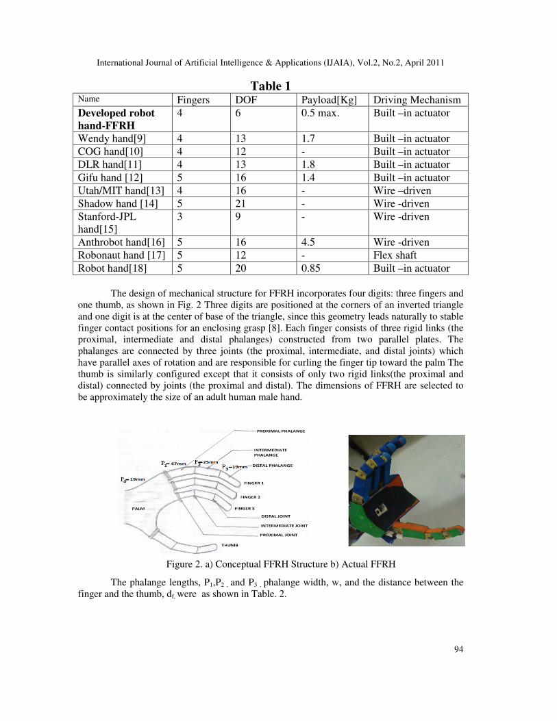
The design of mechanical structure for FFRH incorporates four digits: three fingers and
one thumb, as shown in Fig. 2 Three digits are positioned at the corners of an inverted triangle
and one digit is at the center of base of the triangle, since this geometry leads naturally to stable
finger contact positions for an enclosing grasp [8]. Each finger consists of three rigid links (the
proximal, intermediate and distal phalanges) constructed from two parallel plates. The
phalanges are connected by three joints (the proximal, intermediate, and distal joints) which
have parallel axes of rotation and are responsible for curling the finger tip toward the palm The
thumb is similarly configured except that it consists of only two rigid links(the proximal and
distal) connected by joints (the proximal and distal). The dimensions of FFRH are selected to
be approximately the size of an adult human male hand.
The phalange lengths, P1,P2 , and P3 , phalange width, w, and the distance between the
finger and the thumb, df, were as shown in Table. 2.
Figure 2. a) Conceptual FFRH Structure b) Actual FFRH

International Journal of Artificial Intelligence & Applications (IJAIA), Vol.2, No.2, April 2011
95
Table 2: Measurements of the various parameters of Robotic Hand
The distance between the two fingers, dff, was computed to be the distance between the
fourth and index finger to give the largest human finger displacement. The thickness of the
supports t, was chosen for availability and strength. To reduce construction costs, we
configured the three fingers identically and the thumb to have identical link lengths as the
proximal and intermediate links of the fingers.
Each digit is controlled by a single antagonistic pair of tendons which are routed over a
system of pulleys and idlers as shown in the Fig.3. The pulleys act as routers to create angular
displacement of the link , but do not transfer any torque to the joint. Each phalange consists of a
pulley located at the joint and an idler located at the center of the phalange. The opposing
tendon controlling the finger are routed in opposite direction over the pulley and idler. The path
of the tendon to this system works as a differential mechanism. One end of each tendon is
attached to the tip of the distal phalange and the other is wound about a spool attached to the
shaft of a single remotely located geared DC motor. Using feedback sensors, the finger joint
motion is controlled by relays which are in turn controlled by microcontroller and also the
finger can be locked at any stage within the workspace. The tendons in each finger are wound
in both directions depending on the DC motor direction. In this configuration, the motors
control the relative length of the tendons when irregular object is selected. The complete
mechanical structure of one finger’s joints movement and lock control mechanism is shown in
Fig. 3.
.
For practical reasons, epoxy is selected as the material for the plates (fingers) since it is
strong, rigid, lightweight, relatively in expensive, and easy to machine. We also choose epoxy
Distance between joints Value(mm)
Palm to proximal joint – P0 19
Proximal to intermediate joint – P1 47
Intermediate to distal joint – P2 25
Distal joint to digit tip – P3 19
Joint to end of phalange – l 9
Phalange width – w 19
Finger to Finger - dff 44
Thumb & fingers - dft 75
Support thickness – t 3
Proximal joint pulley radius – R1 9
Intermediate joint pulley radius – R2 8
Distal joint pulley radius – R3 6
Fig.3. Finger Structure

International Journal of Artificial Intelligence & Applications (IJAIA), Vol.2, No.2, April 2011
96
for the arm, wrist, and palm plates since it is not as susceptible to wear. Dial cords with small
diameter plastic tubes as sleeves are used for the tendons of the digit since these are flexible.
The Graspar robotic hand differs from many other hands [19,20,21] in that the joints of each
finger are independently controlled for motion. Since the joint axes of each digit are parallel,
the motion of each finger lies on a plane. The digits are mounted such that their planar
workspaces are parallel and therefore do not collide. The motion of a Graspar finger as the
digit’s driving motor is activated by the keypad or wireless feedback network.
3. Electronic Hardware Design:
The Electronic hardware design consists of three main parts namely Four digit Robot
hand, Control unit and a Feedback unit. The Four digit Robot hand consists of three fingers and
an opposing thumb and each digit is connected to the geared DC motor. The movements of the
digits are controlled by the geared DC motors. The geared DC motors are controlled by the
Control unit. The functional block diagram of the Control unit is shown in the Fig.5. The
Controller unit has 5x5 Key Pad, Decoders, an 89v52 Microcontroller, Relay Drivers for geared
DC motors, LCD display, and a 433 MHz Receiver for feedback. The Key Pad is interfaced to
Microcontroller via key decoder logic, parallel I/O interface 8255. The keypad consists of Keys
for opening and closing of each digit, wrist up and down, Base clockwise and counters
clockwise, Pick and Place and Home position. The digit or base or wrist is moved, whenever
the corresponding key is pressed. The signals from the Keypad are fed to 8255 IC(PPI) through
Key decoder. The decoded signals are given to the Microcontroller and the corresponding
relays are activated. The relays in turn energize the geared DC motors. All the Four fingers use
DC geared motor drivers with relays, for motion control of finger joints with pitch of 45
degrees maximum. Wrist geared DC motor drives the wrist with roll and pitch of maximum 180
degrees. The opening and closing of any digit indicated on the LCD display(Fig.4). The hand
moves after getting a signal from the Key Pad and rotates up to 360 degrees (free rotation).The
input from finger limit sensors placed on palm is used to control the free rotation of the finger.
Figure 4. a)Controller unit b) Keypad c) LCD Display

International Journal of Artificial Intelligence & Applications (IJAIA), Vol.2, No.2, April 2011
97
The feedback unit consists of IR sensor placed on the palm, a microcontroller, a
433MHz transmitter and a 433MHz Receiver. IR sensors placed on the Palm are used to sense
the presence of an object. Whenever an object is identified on the workspace and is sensed by
the sensor, the object is hunted and the process of object hunt is shown in Fig.1. The operation
of Microcontroller-based robot hand is achieved through control software written in Assembly
Language. Fourteen independent commands are incorporated into this for the following joints:
Fore finger close and open, Middle finger close and open, Ring finger close and open, Thumb
finger close and open, Wrist up and down, Base clockwise and counter clockwise, Pick and
Place and Home position.
4. Software Design
The goal in software design of FFRH is to have a simple, minimal computation control
strategy[21,22]. The design of the control program is divided into different subroutines namely
initialization subroutine, keypad subroutine, fingers and palm subroutine, sensor and feedback
subroutine and object hunt subroutine. The robot system interfaces to FFRH using 14
independent commands for the following joints: Fore finger close and open, Middle finger
close and open, Ring finger close and open, Thumb finger close and open, Wrist up and down,
Base clockwise and counter clockwise, Pick and Place and Home position. Fig.6. shows the
control program of the FFRH.
Fig.6. Control Program
FFRH CONTROL EXECUTIVE
Initialisation Grasping
Pick/place
Keyboard Fingers and
Wrist
Sensors
Feedback
LCD Display
Fig.5. Functional Block Diagram of FFRH

International Journal of Artificial Intelligence & Applications (IJAIA), Vol.2, No.2, April 2011
98
Feedback to the motors is provided by IR sensors/simple contact switches mounted on
the grasping surface of palm. The FFRH is currently using slightly modified contact switches
mounted in parallel along the length of each phalange and added rubber sheathing under the
lever of a generic limit switch and over the surface of a small push button switch to increase the
amount of pressure needed to close the switch, to dampen bouncing often associated with
switches, to increase the area in which the contact can be sensed, and to provide additional
friction between the finger tip and the object.
Similarly, contact switches/IR sensors are used for grasping. Each phalange has contact
switches mounted on the grasping surface of the finger. When IR sensor identifies an object
within the workspace, the corresponding relays will operate to Grasp the object, it shortens the
grasp tendon of each finger until a certain contact pattern is noticed on the digits. To execute a
finger tip grasp, Graspar shortens the grasp tendon until the contact switches on the distal
phalanges of all three digits are closed. For an enclosing grasp, Graspar shortens the grasp
tendon until contact is made on all of the phalanges. If at any time the contact position is lost,
grasper then continues to shorten the grasp tendon of the digit until contact is re established.
Therefore, when a pick and place command is provided by key from keypad is issued to the
Graspar hand, it simply moves simultaneously the motors to shorten the release tendons until
contact is made on all the phalange mechanical stops.
5. EXPERIMENTAL RESULTS
The authors have constructed and tested a prototype version of this robot hand as
shown in Fig 5. The robot hand system performs a finger tip grasp of a screwdriver and an
enclosing grasp of a tin. The controlling software has been written in the Assembly language to
control it. The hand has been mounted on the Microcontroller-based Robot hand fabricated as
shown in Fig. 5. The hand weighs around 4 kgs and the motors are mounted on the base of the
robot.
To test the grasping ability of the hand, it was made to grasp different objects, each
having different shape, size, surface conditions and hardness. The object was held so that the
center of mass was within the workspace volume of the thumb and fingers and oriented to grasp
so that the major axis of the object was parallel to the palm and aligned with the fingers. Once
the objects were crudely positioned in the work space of Graspar, the hand was issued a pick
command switch. The grasp was determined to be successful if the hand correctly held the
object autonomously.
The performance specifications of Graspar that is implemented and tested are as
follows: Maximum weight/payload is 1 kg, Object topology is arbitrary, independent degrees of
freedom are 6, maximum diameter of sphere is 120 mm, and minimum diameter of sphere is 30
mm. An interesting aspect of this design is that the ranges of weight can be increased by adding
more powerful motors and cables of higher tensile strength. Since these motors are mounted
remotely, they do not add to the load of the manipulator. This enables the hand to be configured
for the application by the selection of the appropriate motors. To test size restrictions on
objects, experiments are performed at grasping spherical objects.
6. CONCLUSIONS
A four fingered robotic hand has been designed, built, and tested. The hand design is
based on connected differential mechanisms and has been designed to be inexpensive,
mechanically simple, and easy to control. The tendoning system of the differential mechanism

International Journal of Artificial Intelligence & Applications (IJAIA), Vol.2, No.2, April 2011
99
provides the hand with the ability to conform to object topology and therefore providing the
advantage of using a simple control algorithm. The achievement of this hand is to demonstrate
that reliable grasping can be achieved with inexpensive mechanisms and IR sensors. The
authors have demonstrated that this hand can grasp a variety of objects with different surface
characteristics and shapes without having to reconstruct a surface description of the object. This
grasp is successfully completed as long as the object is within the workspace of the hand.
The control algorithm used by FFRH is extremely simple as was the goal of the design.
The controller takes a high-level command from the user and produces a successful grasp of the
object that is within the workspace of the hand. Unlike most robot hands which use joint
position measurement for control feedback, it uses only inexpensive simple contact/IR sensors.
These sensors are being used primarily due to cost considerations, but have certain limitations.
The advantage of designed robot hand is its simplicity and inexpensive cost. However, this
hand does have some limitations. It cannot be controlled to perform fine manipulations like
writing. The Graspar robotic hand was designed as a first step in a future project that will
integrate vision and grasping to control a robot to grasp objects and the future work will use a
simple stereo vision system to determine the topology of the desired object and to visually
move the robot hand so that the desired object is aligned within the workspace of the Graspar.
The simple control algorithm developed in this project will be applied to the future project in
order to grasp an arbitrary object. As the robot hand system moves the contact switches/IR
sensors will be monitored to determine the successful grasping. This method is relatively
simpler than the hugging algorithm presented for a robot hand configured as Graspar which
relies on dense contact sensing [5,13]. The total robot hand system has independent control of
finger joints of each finger leading to flexible control of finger motion as compared to the three
fingered grasper [23,24,25]. Fig.7. shows the robot hand grasping different objects of different
geometry.
Fig.7. The FFRH grasping a variety of objects.(Bulb, Bottle, Ball, Tin, and Duster).

International Journal of Artificial Intelligence & Applications (IJAIA), Vol.2, No.2, April 2011
100
References:
[1] S.C.Jacobsen, et al.(1986) “Design of the UItah/MIT Dexterous Hand,” Proc. IEEE Inter
Conf.on Robotics and Automation, pp 1520-1532.
[2 ] K.Salibury and C Ruoff(1981) “The Design and Control of a Dexterous Mechanical Hand”
Proc. 1981 ASME Computer Conference, Minneapolis, MN, USA
[3] A.R.Zinc, J J Kyriakopoulos(1993), “Dynamic Modeling and Force/Position Control of the
Anthrobot Dexterous Robot Hand”, Proc of the IEEE Conf. on Decision and Control.
[4] Ikuo Yamano et al (2005), “Five–Fingered Robot Hand using Ultrasonic Motors and Elastic
Elements”, Proceeding of the 2005 IEEE/RSJ International Conference on Robots and System,
pp. 2673-2678.
[5] N.Ulrich, et al (1988) A Medium Complexicity Complant End –Effector “Proc.IEEE. Inter.
Conf. On Robotics And Automation.
[6] S.Ramasamy and M.R.Arshad, "Robotic Hand Simulation With Kinematics and Dynamic
Analysis", Intelligent Systems and Technologies for the New Millenium - TENCON 2000
Proceedings (IEEE), III-178, Kuala Lumpur.
[7] Bicchi, A. (2000) hands for Dexterous Manipulation and Robust Grasping: A Difficult
Road Toward Simplicity. IEEE Transactions on Robotics and Automation 16 (6) 652-662.
Piscataway, IEEE press.
[8] Operating Manual (Dec. 2000) for the Myoelectric Prosthetic Hand. Harada Electronics
Industry, Inc.
[9] Toshio Morita, Hiroyasu Iwata and Shigeki Sugano(2000) “Human Symbiotic Robot Design
based on Division and Unification of Functional Requiements”, Proceedings of the 2000 IEEE
International Conference on Robotics and Automation, pp.2229-2234.
[10] Yoky Matsuoka(1997) “The Mechanism in a Humanoid Robot Hand”, Autonomous Robots,
Vol.4, No. 2, pp.199-209.
[11] J. Butterfass, M. Grebenstein, H. Lieu and G. Hirzinger(2001) “DLR-Hand II: Next Generation
of a Dextrous Robot Hand”, Proceedings of the 2001 IEEE International Conference on Robotics
and Automation, pp.109-114.
[12] H. Kawasaki, T. Komatsu and K. Uchiyama(2002) “Dexterous Anthropomorphic Robot Hand
With Distributed Tactile Sensor: Gifu Hand II. ”, IEEE /ASME Transactions on Mechatronics, Vol.
7, No. 3, pp. 296-303.
[13] S. C. Jacobsen, E. K. Iversen, D. F. Knutti, R. T. Johnson and K. B. Biggers(1986) “Design of the
Utah/MIT Dexterous Hand”, Proceedings of the 1986 IEEE International Conference on Robotics
and Automation, pp. 1520-1532.
[14] http://www.shadow.org.uk/products/newhand.shtml.
[15] J. K. Salisbury, M.T. Mason: “Robot Hands and the Mechanics of Manipulation”, MIT Press,
1985
[16] K. J. Kyriakopoulos, J. V. Riper, A. Zink and H. E. Stephanou(1997) “Kinematics Analysis and
Position/Force Control of the Anthrobot Dexterous Hand”, IEEE Transactions on Systems, Vol. 27,
No. 1, pp. 95-103.
[17] C. S. Lovchic and M. A. Diftler: The Robonaut Hand(1999) “A Dexterous Robot Hand for Space”,
Procd. of the 1999 IEEE International Conference on Robotics and Automation, pp. 907-912.

International Journal of Artificial Intelligence & Applications (IJAIA), Vol.2, No.2, April 2011
101
[18] Ikuo Yamano and Takashi Maeno(2005) “Five-fingered Robot Hand using Ultrasonic Motors
and Elastic Elements”,
Proceedings of the 2005 IEEE International Conference on Robotics and
Automation pp. 2673-2678.
[19] Emily Tai (2007), “Design Of An Anthropomorphic Robotic Hand For Space Operations”,
M.S. Thesis, Department of Aerospace Engineering, University of Maryland, USA
[20] J. Butterfass, et al (2001) “DLR-Hand II: Next Generation of Dexterous Robot Hand,
Proceedings of the 2000 IEEE International Conference on Robotics and Automation, pp. 109-
114.
[21] S. Parasuraman(2008), “Kinematics and Control System Design of Manipulators for a
Humanoid Robot”, Proceedings of World Academy of Science, Engineering And Technology,
Volume 39, pp.7-13 ISSN 1307-6884
[22] Mina Terauchi, et al (2008) “The implementation of robot finger using Shape Memory Alloys
and Electrical Motors”, IEEE transactions on industry applications, volume 128 issue 5, pp.
654-660.
[23] Valentin Grecu, et al (2009) “Analysis of Human Arm Joints and Extension of the Study to
Robot Manipulator”, Proceedings of the International MultiConference of Engineers and
Computer Scientists 2009 Vol II IMECS.
[24] Jill D.Crisman, et al (1996) “Graspar A Flexible Easily Controllable Robotic Hand “,IEEE,
Robotics and Automation Vol 3,No2, pp. 32-38.
[25] S. Parasuraman, and Ler Shiaw Pei (2008), “Bio-mechanical Analysis of Human Joints and
Extension of the Study to Robot.” Proceedings of World Academy of Science, Engineering and
Technology Volume 29 May 2008, pp. 1-6, ISSN 1307-6884.
Authors:
Dr. P. Seetha Ramaiah received his Ph.D. in Computer Science and Systems Engineering
from Andhra University in 1990. He is presently working as a Professor in the department of Computer
Science and Systems Engg. Andhra University, Visakhapatnam, INDIA. He is
the Principal Investigator for several Defence R&D projects and Department of
Science and Technology projects of the Government of India in the areas of
Bionic Implants and robotics. He has published ten journal papers, and presented
Fifteen International Conference papers in addition to twenty one papers at
National Conferences in India. His areas of research includes Bio-Electronics
Systems, Safety-Critical Computing- Software Safety, Computer Networks,
VLSI and Embedded Systems, Real-Time Systems,Microprocessor-based System
Design, Robot Hand-Eye Coordination, Signal Processing algorithms on fixed-
point DSP processors.
M.Venkateswara Rao received his M.Phil. in Physics from Andhra University
in 1990. He has done M.Tech in Computer Science Engineering from Andhra
University, in 2000. He is presently working as Associate Professor in the
department of Information Technology, GITAM University, Visakhapatnam,
INDIA. He has published 1 journal paper, and presented two papers at National
Conferences in India. His areas of research includes Embedded Systems and
Robotics.
International Journal of Artificial Intelligence & Applications (IJAIA), Vol.2, No.2, April 2011
102
Dr. G.V.Satya Narayana received his Ph.D. in Physics from Andhra University
in 1992. He has done M.Tech in Information Technology from Andhra
University. He is presently working as a Professor in the department of
Information Technology, Raghu Institute of Technology, Visakhapatnam,
INDIA. He has published 3 journal papers, and presented two papers at National
Conferences in India. His areas of research includes Embedded Systems and
Robotics.