determining system requirements object-oriented...
TRANSCRIPT

Determining System requirements
&
Object-Oriented Analysis and Design: Sequence Diagrams and Activity Diagrams
(Lecture 6)
Sunday 17/3/2013
Dr.Rania Elgohary

Objectives
To introduce the concepts of user and
system requirements
To describe functional and non-functional
requirements

© 2008 by Prentice Hall 3Chapter 8 Appendix
Learning Objectives
Understand how to represent system logic with
sequence diagrams.
Understand how to represent system logic with
activity diagrams.

The Rational Unified Process
A modern process model derived from the
work on the UML and associated process.
Normally described from 3 perspectives
A dynamic perspective that shows phases
over time;
A static perspective that shows process
activities;
A proactive perspective that suggests good
practice.

RUP phase model
Phase iteration
Inception Elaboration Construction Transition

RUP phases Inception
Establish the business case for the system.
Elaboration
Develop an understanding of the problem
domain and the system architecture.
Construction
System design, programming and testing.
Transition
Deploy the system in its operating environment.

RUP phase

RUP good practice
Develop software iteratively
Manage requirements
Use component-based architectures
Visually model software
Verify software quality
Control changes to software

Requirements engineering RE
The process of establishing Customer Services and the Constraints (CS & C)
Rs are the descriptions of (CS & C) that are generated during the RE process.

What is a requirement?
high-level abstract statement
of a service constraint
or of a system constraint
to a detailed mathematical
functional specification.

Types of requirement
User requirements
the services provided by the system ,its operational constraints. Written for customers.
System requirements
1- A structured document setting out
(detailed descriptions of the system’s functions SF, services S and operational constraints OC.
2- Defines what should be implemented so may be part of a contract between client and contractor.

Requirements readers

Functional and non-functional requirements
Functional requirements
Statements of services the system should provide,
how the system should react to particular inputs ,
how the system should behave in particular situations.
Non-functional requirements
constraints on the services or functions offered by the
system such as timing constraints, constraints on the development process, standards, etc.
Every Condition is non
functional
Every process is functional

Functional requirements
Describe functionality or system
services.
Depend on the type of :
software, expected users and the type
of system.
what the system should do
describe the system services in detail.

The LIBSYS system (library
system)
A library system that provides a single
interface to a number of databases of
articles in different libraries.
Users can search for, download and
print these articles for personal study.

Examples of functional requirements
The user able to search either all of the
initial set of databases or select a subset
from it.
The system provide viewers for the user
to read documents in the document store.
Every order allocated a unique identifier
(ORDER_ID) which the user shall be able
to copy to the account’s permanent
storage area.

Requirements completeness and
consistency Complete
They should include descriptions of all
facilities required.
Consistent
There should be no conflicts or
contradictions in the descriptions of the
system facilities.
In practice, it is impossible to produce a
complete and consistent requirements
document.

Non-functional requirements These define system properties and constraints
reliability,
response time
storage requirements.
Constraints are I/O device capability,
system representations, etc.
Non-functional requirements may be more critical than functional requirements.
If these are not met, the system is useless.

Non-functional classifications
Product requirements
Requirements which specify that the delivered
product must behave in a particular way e.g.
execution speed, reliability,..
8.1 The user interface for LIBSYS shall be
implemented as simple HTML without frames or
Java applets.

Organisational requirements
Requirements which are a consequence of
organisational policies and procedures e.g.
process standards used, implementation
requirements, etc.
9.3.2 The system development process and
deliverable documents shall conform to the process
and deliverables defined in XYZCo-SP-STAN-95.
© 2008 by Prentice Hall 20Chapter 8 Appendix

External requirements
Requirements which arise from factors which are
external to the system and its development
process e.g. interoperability requirements,
legislative requirements, etc.
7.6.5 The system shall not disclose any personal
information about customers apart from their name
and reference number to the operators of the system.
© 2008 by Prentice Hall 21Chapter 8 Appendix
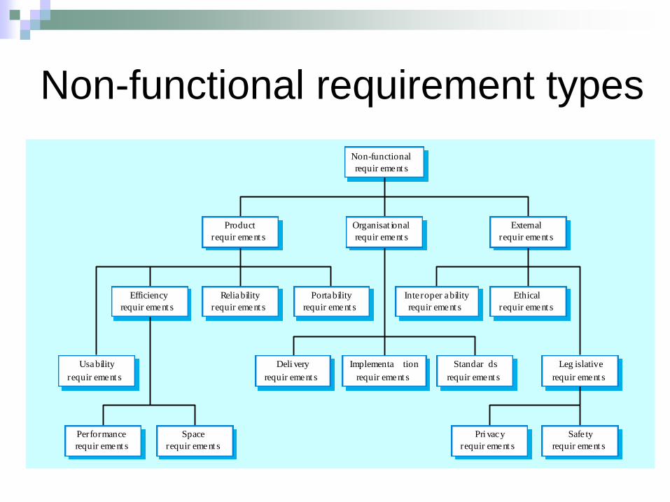
Non-functional requirement types
Performance
requir ement s
Space
requir ement s
Usability
requir ement s
Efficiency
requir ement s
Reliability
requir ement s
Portability
requir ement s
Inte roper ability
requir ement s
Ethical
requir ement s
Leg islative
requir ement s
Implementa tion
requir ement s
Standar ds
requir ement s
Deli very
requir ement s
Safe ty
requir ement s
Pri vacy
requir ement s
Product
requir ement s
Organisat ional
requir ement s
External
requir ement s
Non-functional
requir ement s

User requirements
User requirements are defined using
natural language, tables and diagrams
as these can be understood by all
users.

System requirements
More detailed specifications of system functions, services and constraints than user requirements.
They are intended to be a basis for designing the system.
They may be incorporated into the system contract.
System requirements may be defined or illustrated using system models UML

Definitions and specifications
1. The softw are m ust pr ovide a means of representing and
1. accessing e xternal files cr ea ted b y other tools .
1.1 The user should be pr ovided with facilit ies to define the type of
1.2 external files .
1.2 Each e xternal file type ma y have an associa ted tool w hich ma y be
1.2 applied to the file .
1.3 Each e xternal file type ma y be r epr esented as a specific icon on
1.2 the user’ s displa y.
1.4 Facilities should be pr ovided f or the icon r epresenting an
1.2 external file type to be defined b y the user .
1.5 When a user selects an icon r epr esenting an e xternal file , the
1.2 effect of that selection is to apply the tool associated with the type of
1.2 the external file to the file represented by the selected icon.
User requir ement definition
System requir ements specification

Guidelines for writing requirements
Use language in a consistent way. Use
shall for mandatory requirements,
should for desirable requirements.
Use text highlighting to identify key
parts of the requirement.
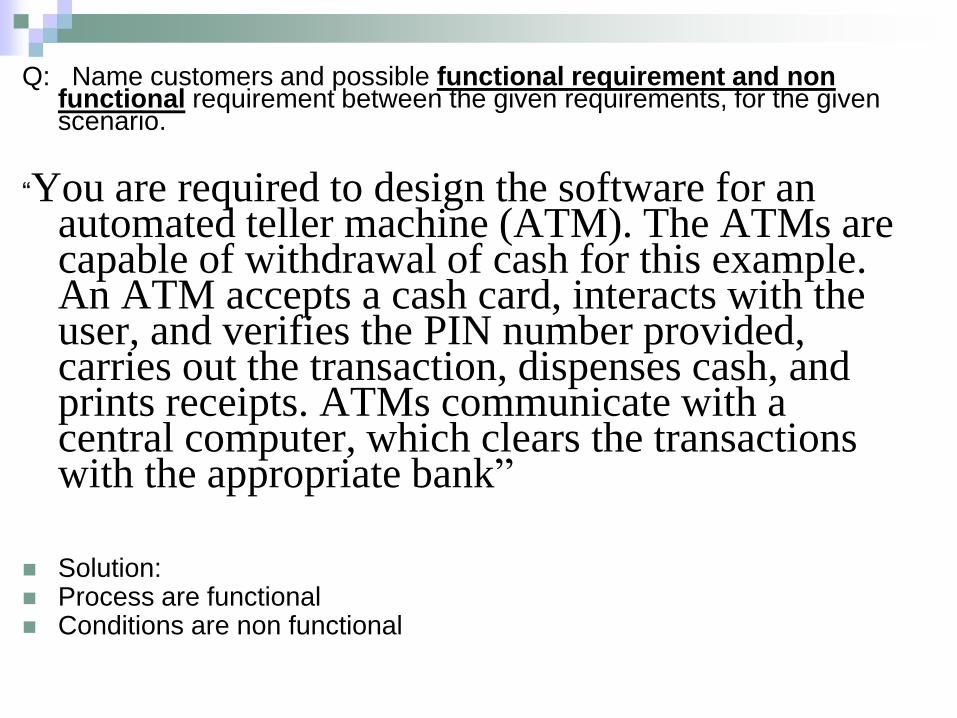
Q: Name customers and possible functional requirement and non functional requirement between the given requirements, for the given scenario.
“You are required to design the software for an automated teller machine (ATM). The ATMs are capable of withdrawal of cash for this example. An ATM accepts a cash card, interacts with the user, and verifies the PIN number provided, carries out the transaction, dispenses cash, and prints receipts. ATMs communicate with a central computer, which clears the transactions with the appropriate bank”
Solution: Process are functional Conditions are non functional

Interaction Diagrams
• Shows, step-by-step, flows through a use case:- What objects are needed for the flow- What messages the objects send to each other- What actor initiates the flow- What order the messages are sent
28
system analysis and
design

Dynamic Modeling: Sequence Diagrams
Sequence diagram: depicts the interactions among objects
during a certain period of time.
May be presented either in
a generic form or in
an instance form.
Generic form shows all possible sequences of interactions
– sequences corresponding to all the scenarios of a use
case.
Instance form shows the sequence for only one scenario.
Chapter 8 Appendix 29© 2008 by Prentice Hall

Dynamic Modeling: Sequence Diagrams (Cont.)
Elements of a sequence diagram
Objects: represented by boxes at top of diagram.
Lifeline: the time during which an object exists.
Messages: means by which objects communicate
with each other.
Chapter 8 Appendix 30© 2008 by Prentice Hall

Interaction Diagrams
•In order for one class to send a message to another on aSequence diagram, there must be a relationship between the twoclasses
31
system analysis and
design

Sequence Diagrams
• Sequence diagrams are interaction diagrams ordered by time
• Each diagram represent one of the flows through a use case
•Sequence Diagram users:•Users can look at these diagrams to see the specifics of theirbusiness processing
•Analysts see the flow of processing in the Sequence diagrams
•Developers see objects that need to be developed andoperations for those objects
•Quality assurance engineers can see the details of the processand develop test cases based on the processing
32
system analysis and
design

Sequence Diagrams
• Actors and Objects shown at the top of the diagram
• Each object has a lifeline, drawn as a vertical dashed line below theobject
- The lifeline begins when the object is instantiated and endswhen the object is destroyed
• A Message is drawn between the lifelines of two objects to showthat the objects communicate (each message will become anoperation). Messages can also be reflexive, showing that an object
is calling one of its own operations
33
system analysis and
design

Dynamic Modeling: Sequence Diagrams (Cont.)
Activation: the time period during which an object
performs an operation. (Object is active)
Synchronous message: a type of message in which
the caller has to wait for the receiving object to finish
executing the called operation before it can resume
execution itself.
It has always an associated return value.
Chapter 8 Appendix 34© 2008 by Prentice Hall

Sequence Diagrams: Messages Synchronization
• Synchronous: When the client sends the message andwaits until the supplier has acted upon the message
35
system analysis and
design

Dynamic Modeling: Sequence Diagrams (Cont.)
Simple message: a message that simply transfer control
from the sender to the recipient without describing the
details of the communication.
Asynchronous message: a message in which the
sender does not have to wait for the recipient to handle
the message.
It is common in concurrent, or parallel processing
(multiple objects running in parallel).
Chapter 8 Appendix 36© 2008 by Prentice Hall

• Asynchronous: The client sends the message to thesupplier. The client then continues processing, withoutwaiting to see if the message was received or not
37
system analysis and
design
Sequence Diagrams:

Sequence Diagrams:
• Balking: The client sends the message to the supplier. Ifthe supplier is not immediately ready to accept themessage, the client abandons (leave) the message
38
system analysis and
design

• Timeout: The client sends the message to the supplierand waits a specified amount of time. If the supplierisn't ready to receive the message in that time, the clientabandons the message
39
system analysis and
design
Sequence Diagrams:

• Procedure Call: The client sends the message to thesupplier. The client then must wait until the entire nestedsequence of messages is processed before continuing
40
system analysis and
design
Sequence Diagrams:

• Return: This option indicates the return from aprocedure call
41
system analysis and
design
Sequence Diagrams:

Designing a Use Case with a Sequence Diagram
© 2008 by Prentice Hall 42Chapter 8 Appendix
Figure 8-11 Sequence diagram for a class registration scenario without prerequisites
•Guard Cond.
•Self Delegation.
•Persistent
(continue) Object.
•Y axis & X axis.
•Objects arrange.
•Activation.

Association: Bidirectional
Public class Customer
{
public Flight theFlight;
public Customer()
{
}
}
Public class Flight
{
public Customer theCustomer;
public Flight()
{
}
}43

Association: Unidirectional
Public class Customer
{
public Customer()
{
}
}
Public class Flight
{
public Customer theCustomer;
public Flight()
{
}
}
44

Combined Fragments
1. Alternatives:
45

Mistakes to avoid in Sequence
Diagrams
46
system analysis and
design

Avoid too much detail
Usually, a typical mistake that software diagrammers
usually make is adding too much detail when working with
sequence diagrams. The issue is that adding too much
detail ends up with making the diagrams more difficult to
read .
47

Messages should flow from Left to Right
the message flow should start from the top left corner. Because we
read from the left to the right.
However, there are certain exceptions when it comes to this logical
flow, such as, when objects pairs invoke operations on each
other.
48
system analysis and
design

Avoid Sequence Diagram when you have simple
logicOne of the most common mistakes that most of us do is waste time doing
too many diagrams for every single use case, one for the basic course of
action and one for each alternate course. It is best to design a sequence
diagram only when you have complex logic that you have to contend with. If
the logic is easy to figure out, having a sequence diagram would not really add
any value.
49
system analysis and
design
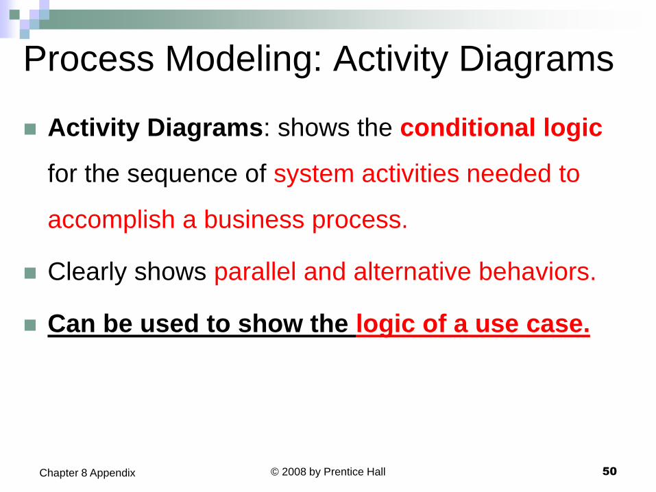
Process Modeling: Activity Diagrams
Activity Diagrams: shows the conditional logic
for the sequence of system activities needed to
accomplish a business process.
Clearly shows parallel and alternative behaviors.
Can be used to show the logic of a use case.
Chapter 8 Appendix 50© 2008 by Prentice Hall

Activity Diagram
• Activity diagrams illustrate the flow of functionality in asystem
• It used in requirements gathering to illustrate the flow ofevents through a use case
• These diagrams define where the workflow starts, whereit ends, what activities occur during the workflow, and inwhat order the activities occur
• An activity is a task that is performed during the workflow

Elements of Activity DiagramNotationRepresentationElement
End State
Start State
Activity
- Show where the flow begins
- Each activity diagram must have one and only one start state
- Show where the flow ends.
- You can have more than one end state on the diagram (Optional)
A step in the process - a task that is performed during the workflow
Select Flight

Elements of Activity Diagram cont.
NotationRepresentationElement
Object Flows
Objects
Transitions
- An entity that activity is used or changed in the flow
- You can understand where and how the object's state changes.
- Link objects to activities
-From an activity to the object it changes-From the object to the activity that needs to use it (as input)
shows how the flow of control moves from one activity to another
Object Name
[State]

Process Modeling: Activity Diagrams (Cont.)
Elements of Activity Diagrams:
Activity: a behavior that an object carries out while in a
particular state.
Transition: a movement from one activity or state to
another.
Branch: a diamond symbol containing a condition
whose results provide transitions to different paths of
activities.
Chapter 8 Appendix 54© 2008 by Prentice Hall

Process Modeling: Activity Diagrams (Cont.)
Synchronization bar: horizontal or vertical
bars denoting parallel or concurrent paths of
activities.
Fork: the beginning of parallel activities.
Join: the end of parallel activities.
Swimlanes: columns representing different
organizational units of the system.
Chapter 8 Appendix 55© 2008 by Prentice Hall

Reserve Seat
[Invalid account, credit
system not available ]
Ticket
Enter Credit Information
[Approved]
Generate ConfirmationNumber
[Purchased]
Ticket
[Unconfirmed]

Transitions: Limitations cont.
• Guard condition:
• While an event triggers a transition, a guard conditioncontrols whether or not the transition can occur• If a guard condition is present, it must be true in orderfor the transition to occur• The guard condition is listed along the transitionarrow, following any event, and is enclosed in squarebrackets
Elements of Activity Diagram
Reserve seat Generate Confirmation Number
[New reservation]

Reserve Seat
[Invalid account, credit
system not available ]
Ticket
Enter Credit Information
[Approved]
Generate ConfirmationNumber
[Purchased]
Ticket
[Unconfirmed]
Send E-mail Display Confirmation Number

Process Modeling: Activity Diagrams.
Chapter 8 Appendix 59© 2008 by Prentice Hall
Figure 8-14
Activity diagram
for a customer
order process.