detailed design of a forest surveillance uav
TRANSCRIPT
Detailed design of a forest surveillance UAV
Oleh [email protected]
Instituto Superior Técnico, Universidade de Lisboa, Portugal
November 2018
Abstract
The aim of this work is to develop an Unmanned Aerial Vehicle (UAV) for fire surveillance byusing an adequate, low-cost platform for high risk missions. This project, named DeltaSpotter, hada previously developed first working prototype, which in combination with a market research allowedfor a better understanding of the characteristics necessary for an efficient long endurance UAV design.After detailed analysis of several possible configurations, the flying wing design was kept, as it wasthe most adequate for the mission requirements. Extensive research in regard to materials, methods ofmanufacturing and propulsion systems was completed, resulting in lower costs without compromisingperformance.
In addition, both size and shape of the UAV were defined. With the conceptual design completed,ensues the stability analysis and flight envelop of the design. This was followed by geometry modeling(by means of CAD software) and structural design (using a finite element software). To finish thedesign, the aerodynamic performance was studied, using CFD, which allowed for the calculation of atheoretical endurance value. The resulting DeltaSpotter aircraft has a two hour increase in endurancecompared with the previous version. To finish the development process, several aspects of the drone’smission were described in detail.Keywords: AM Plastic, Foam Core Airfoils, High Risk Missions, Low-Cost, UAV Design.
1. Introduction
In continental Portugal 39% of the territory is forestterrain, which translates into roughly 3,481 thou-sand hectares of land. When looking at reports ex-posing the impact of large fires in last 3 decades, itbecomes transparent that the areas affected are sim-ilar year after year, showing a clear flaw in preven-tion and surveillance that needs to be addressed. Tobetter understand the current methods of surveil-lance, several meetings were held with the Por-tuguese entities responsible for forest/fire surveil-lance and monitoring. During these meetings, sev-eral methods were discussed, covering their im-plementation, advantages and shortcomings. fromtheir advantages and implementation to their short-comings. The bulk of these efforts were said torely substantially on monitoring from strategicallyplaced watch-towers. However, these have a limitedrange of vigilance and only fully work after the firstof July. This is clearly ineffective as before this pe-riod there is frequently heat waves across the coun-try that exacerbate the probability and magnitudeof either natural or man-manned fires. This methodis complemented by GNR patrols that survey ar-eas out of range from the towers and discouragepossible arsonists or careless forest visitors. It was
discovered that some entities possess highly techno-logical drones. However, since these were very ex-pensive acquisitions with complicated maintenanceand highly specialized operators (pilots), they aremostly left unused due to fear of losing the equip-ment and initial investment.
With this information, engineers at Centre of En-gineering and Product Development (CEiiA) set todevelop an UAV that would be suitable for highrisk missions (with high probability of loss of equip-ment). In addition, for the UAV to be implementedas a powerful tool of surveillance, it ought to be easyto carry and use without specialized training. Theproject, named DeltaSpotter, had a first prototypebuilt in the summer of 2017 which served as a proofof concept and allowed for testing open source soft-ware and hardware. With mostly positive results,CEiiA gave the approval for the development of along endurance version that should also correct theshortcomings of the first prototype, which will bethe aim of this work.
2. BackgroundThe design process of an UAV depends on the mis-sion requirements. Since the UAV does not requirea person inside, it opens up new possibilities forthe use of design space and allows for more freedom
1
regarding the size, manufacturing techniques andmaterials. It also allows for the simplification ofsome systems and the removal of systematic redun-dancies. The materials in particular may be sim-pler, lighter and cheaper than those typically usedin manned vehicles. This also means that new typesof materials and manufacturing techniques can betested and implemented such as foams, polymersand additive manufacturing. In fact, with noveltyapproaches for both material and manufacturingtechniques, it became feasible to improve the per-formance of aerodynamic surfaces at a reduced cost,without compromising efficiency [1].
2.1. DeltaSpotter V1Before starting the process of development for thelong endurance version of DeltaSpotter, it is impor-tant to introduce the first prototype, DeltaSpotterV1, which was developed in cooperation with theaeronautical team at CEiiA during a Summer In-ternship Program. The author of this work accom-panied the entire development process and partici-pated in the decision making. This prototype wasdesigned as a proof of concept, in order to under-stand if it was feasible to develop a low-cost fullyautonomous platform for high risk missions, in thisparticular scenario to act as a fire detection sys-tem. Accordingly, the system was developed withonly open source software (Mission Planner) andhardware (Autopilot 2.8). The main goal was to un-derstand which features were required and to testthe performance of Mission Planner and Autopi-lot. During the development, there was an effort toalso analyze the market and present the project topossible customers. However, Computational FluidDynamic (CFD) and structural analyses were notperformed, as this phase was still a proof of con-cept.
This prototype was built in order to be a lowcost, lightweight model aircraft. As such, the wingswere made of XPS foam, which has a high capac-ity to absorb impact, while the spar and centralframe were built out of plywood. After the man-ufacturing process was complete, flying tests weresuccessfully performed. Nevertheless, some issueswere reported, such as a limited endurance time andcomplications with the autopilot leveling which wasthought to be caused by the central frame, likelydue to the plywood used in it.
After acknowledging and examining the triumphsand shortcomings of the first prototype, the aim isnow to develop a new UAV for a longer endurance.As was the case with the previous version, the UAVmust take off by hand launching, be low cost, easyto assemble and transport. With this last constrainsin mind, the wing span should not exceed 3m as itwill be transported by GNR patrols, in accordance
to already implemented national surveillance strate-gies. The UAV should also be prepared to carry apayload of around 500 g and withstand gusts around30 to 40 km/h. Finally, an internal structure ade-quate to use in both V1 and V2 will be designed.
2.2. UAV configurationAs mentioned above, the configuration of the UAVdepends on its intended mission. In this case, tosurvey and monitor large areas, an UAV with fixedwings (Conventional Take-Off and Landing, CTOL)would be more effective, as they have longer en-durance and the ability to fly at much higher alti-tudes [1].
In order to choose the most adequate configura-tion, a decision matrix was employed, where fourconfigurations (conventional configurations withtailplane-aft, canard configuration with a tailplaneforward, tail-aft on booms and flying wing) werecompared in accordance to the project require-ments. It was concluded that the flying wing con-figuration is the most suitable configuration for thisapplication, since it is easy to carry and has alow manufacturing price, without compromising themaneuverability and the aerodynamic efficiency.
2.3. Materials and Manufacturing MethodsThe aircraft structure should be lightweight, tomaximize endurance, while being stiff enough tobear the required loads. Moreover, a key factor inkeeping the costs contained is the choice of mate-rials and manufacturing techniques. In this partic-ular case, only cost-effective materials will be an-alyzed, such as foams and polymers. Regardingthe foams, they are inexpensive, easy to shape, re-pair and substitute, while also being lightweight andresistant to impact. This makes foams the idealchoice for wing manufacturing since it ensures alight weight component but does not compromisetheir shock resistance. For the manufacturing ofthe wing itself, a 4 axis hot wire cut will be usedafter airfoil selection and modelling.
The other material of particular relevance to en-sure the development of a cost-effective UAV arepolymers. These are usually known for a rela-tively low weight, resistance to corrosion and lackof conductivity (thermal and electrical). In addi-tion, since they are easy to soften or melt whenheated, and also become firm when cooled, makingthem ideal for heat dependent manufacturing tech-niques. In general, polymers have low prices due tobeing chemically mass produced from petroleum,although there have been significant investmentsin producing polymers from renewable sources (i.e.biofermentation of corn starch) to decrease the con-sumption and dependence of fossil fuels. The mostcommon used polymer filaments include Acryloni-trile Butadiene Styrene (ABS), Polylactide (PLA),
2
Nylon, Polycarbonate (PC), and Polyvinyl Alcohol(PVA).
Recently, Additive Manufacturing (AM) has ex-ploded in popularity due to the flexibility of build-ing a component, layer by layer, based on a com-puter model. It is widely used to build prototypesand components with a small rate of production,providing fast prototyping and production of com-plex geometries. The type of AM technology useddepends on the application and requirements. Inthis case, since CEiiA already owns a Fuse Deposi-tion Modeling (FDM) printer, which is adequate toprint the desired pieces, this will be the techniqueused. In doing so, new investments are avoided.The material to be used for the printing is PLAdue its high tensile strength. In addition, it isbiodegradable, recyclable and sourced from renew-able sources, lowering the UAV’s carbon foot print[2].
2.4. Propulsion SystemAnother key component of the UAV is the propul-sion system, which provides the necessary power topropel the aircraft forward. The power from thepropulsion system must be enough to balance thedrag of the aircraft when it is in cruise mode andit must exceed the drag of the UAV for it to climb.There are several types of propulsion, but only twoare commonly used in UAVs, the Internal Combus-tion engines and Electric Propulsion [1].
Internal Combustion engines use gasoline,methanol or diesel as fuel and are usually usedin long-endurance aircraft. However, due to theirsmall size, engines have numerous deficiencies:they are noisy; polluting; with a high thermalsignature; and produce a lot of vibration, which re-quires reinforcements in the structure and frequentmaintenance [3].
The Electric Propulsion uses an electric motor,which has a smaller number of parts when com-pared to an internal combustion engine, allowingan increase in engine revolutions. Its thrust can becontrolled more precisely and it responds faster tothrottle input due to the high torque available. Inaddition, it requires less maintenance, further low-ering the cost. Taking into account that an electricmotor practically does not have any movable partswhen compared to an internal combustion engine, itallows an increase of the engine revolutions. Over-all it also requires lower maintenance. From an eco-nomical point of view, the electric propulsion is lessexpensive. In addition, it is known to be quiet,without gas emissions and with low vibrations.
Another important factor to consider is that car-rying rechargeable batteries is preferable to in-flammable fuels as it reduces the chances of causinga fire, which in this case would defeat the project’s
purpose. Accordingly, an electric propulsion systemwas selected for this project.
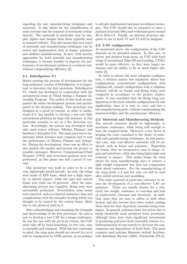
3. Preliminary DesignIn order to conceptualize an unmanned aerial ve-hicle, an iterative process is defined, which is pre-sented in Figure 1.
The definition of the requirements and con-straints, in collaboration with the Portuguese au-thorities, was based in the shortcomings of the firstprototype and in extensive market research. Withthis finalized, the mission profile was designed andboth the aircraft configuration and the propulsionsystem were chosen, thus obtaining a new concep-tual design. At the end of this stage, in decisionpoint D1, the results were analyzed in light of therequirements: if considered accurate enough, theprocess proceeds to the aerodynamic and structuredetailed design; otherwise it returns to the require-ments/constraints step.
A comprehensive design of the structure was car-ried out alongside the aerodynamic analyses. Aftercompletion, the resulting structural design’s perfor-mance was evaluated (decision point D2): if judgedaccurate, the fabrication step initiates; otherwisethe structural and external geometries designs arerevised (to improve aerodynamics).
After building the DeltaSpotter V2 prototype,flight tests will be initiated.
Figure 1: General Design Process.
3.1. Conceptual Design of DeltaSpotter V2This section is related with the conceptual designof the platform which is an iterative process com-
3
posed of five steps (initial weight estimation, air-foil selection, wing configuration, stability analysisand flight envelope). To start, the initial sizing andweight estimation is performed in accordance to thefirst platform. To adapt to a long endurance UAV,it was considered that the battery would represent50% to 60% of the total weight [4]. Accordingly, aweight estimation of 30N was considered.
In order to obtain a first estimation of endurance,the following equation for the electric propulsion isused,
TE =ET ηP
12 ρU
3 S(CDo + 1π ARe ( W
12ρU
2 S)2)
(1)
where TE is the endurance in hours, ηP is thepropulsive efficiency, ρ is the air density, U is thespeed of the UAV, CDo is the zero lift drag, AR isthe wing aspect ratio, e is the osvald factor, W isthe weight of the UAV and S is the wing area.
3.2. AerodynamicsFor the aerodynamic analysis, an open source pro-gram named XFLR5 was used. Vortex LatticeMethod (VLM) was selected for the wing analysis,as it was the most adequate for the shape of thewing.
Since the most important feature of an airfoil fora flying wing is a moment coefficient close to zero,only some airfoils are adequate. Based on publisheddata [5], fourteen airfoils were selected and analyzedin order to obtain the airfoils with the highest valueof CL/CD. These were analyzed at low Reynoldsnumber (5, 000 < Re < 1, 000, 000). From thisanalysis, five airfoils were selected and modified ac-cording to the thickness to chord ratio (t/c) and thethickness in the trailing edge, which must be 5mm(due to the manufacturing technique used).
Selected some potentials airfoils, the wing config-uration ensues. The trapezoidal construction waschosen since it is simple to manufacture and has arelatively low root bending moment. For this typeof wing, the taper ratio should be 40% (i.e. λ = 0.4)[6]. Another essential parameter to define is thesweep angle (Λ). The increment of this angle con-tributes for the directional stability [7], althougha large value of sweep angle reduces the wing effi-ciency (CL/CD). Based on Ref. [8], an appropriatevalue for the sweep tailless UAVs is 15. Another se-lected parameter is the dihedral angle, which in thiscase will be 3o. This angle has a role during landing,as it causes the wing tip to stay above ground, al-lowing the UAV to perform softer landings. Know-ing that the internal structure should be able tobe used in both versions, the root chord and thethickness to chord ratio should be the same of thefirst prototype, meaning that croot = 500mm and
t/croot = 14%. On the other hand the Aspect Ra-tio (AR) was restricted by the wingspan (3m) andthe mean aerodynamic chord, resulting in a valueof 8.57.
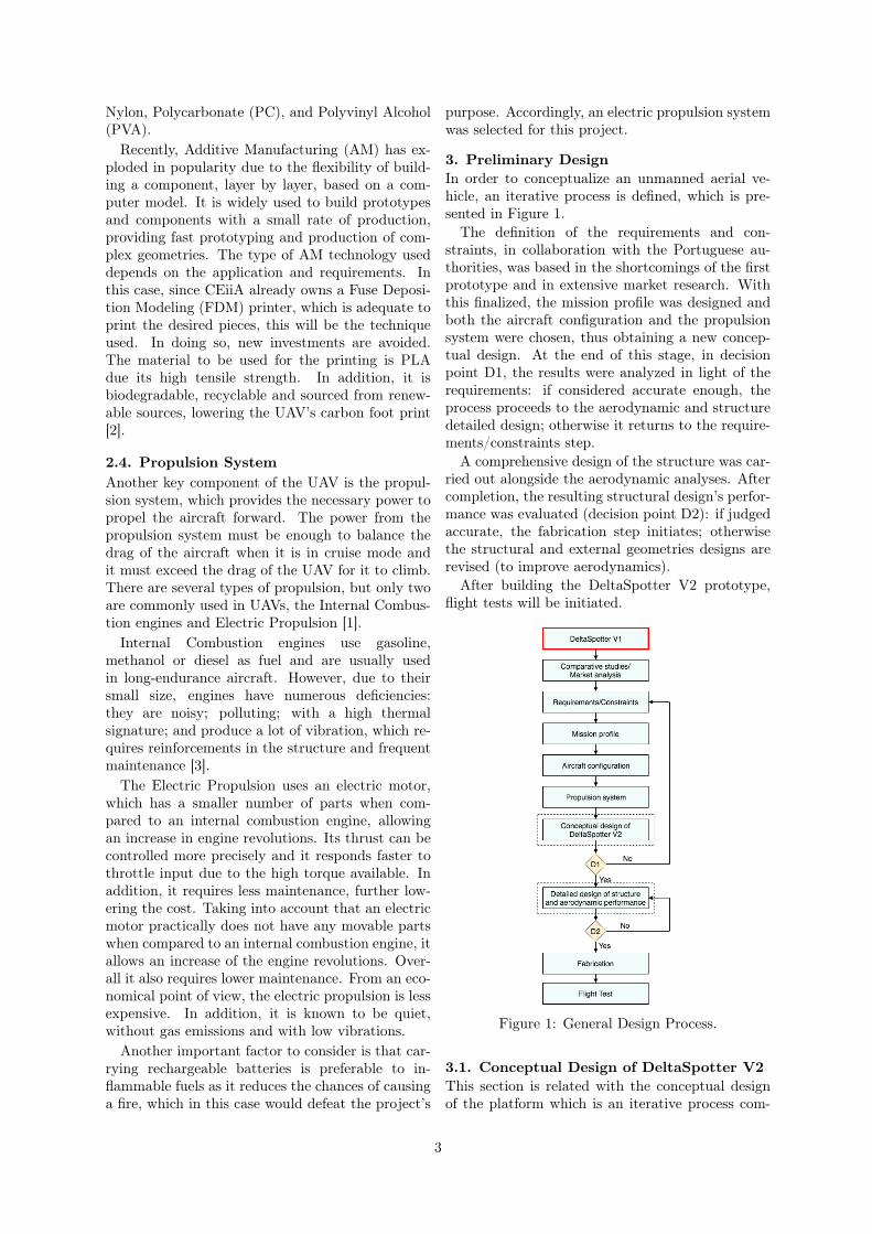
With the size and shape of the wing defined, thepreviously selected and modified airfoils (HS 522-MOD, MH45-MOD, MH 60-MOD MH 61-MODand S5010-MOD) are applied to the wing models,which are then compared between each other. Com-paring the results of CL/CD vs. speed (presentedin Figure 2), CL vs. angle of attack, moment coef-ficient vs. speed and the angle of attack vs speed,from each model, the MH 45-MOD airfoil was foundto be the most adequate.
Figure 2: CL/CD vs. Ux.
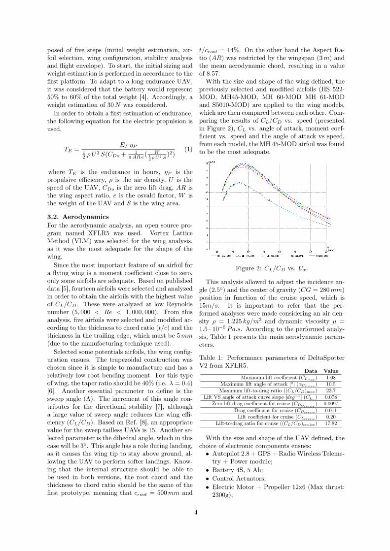
This analysis allowed to adjust the incidence an-gle (2.5o) and the center of gravity (CG = 280mm)position in function of the cruise speed, which is15m/s. It is important to refer that the per-formed analyses were made considering an air den-sity ρ = 1.225 kg/m3 and dynamic viscosity µ =1.5 · 10−5 Pa.s. According to the performed analy-sis, Table 1 presents the main aerodynamic param-eters.
Table 1: Performance parameters of DeltaSpotterV2 from XFLR5.
Data ValueMaximum lift coefficient (CLmax) 1.08
Maximum lift angle of attack [o] (αCLmax) 10.5Maximum lift-to-drag ratio ((CL/CD)max) 23.7
Lift VS angle of attack curve slope [deg−1] (CLα) 0.078Zero lift drag coefficient for cruise (CDOcruise ) 0.0097
Drag coefficient for cruise (CDcruise) 0.011Lift coefficient for cruise (CLcruise) 0.20
Lift-to-drag ratio for cruise ((CL/CD)cruise) 17.82
With the size and shape of the UAV defined, thechoice of electronic components ensues:• Autopilot 2.8 + GPS + Radio Wireless Teleme-
try + Power module;• Battery 4S, 5 Ah;• Control Actuators;• Electric Motor + Propeller 12x6 (Max thrust:
2300g);
4
• Electronic Speed Controller (ESC) 60A;Regarding the weight of the aircraft, the estima-
tion was kept on 30N , where the batteries represent1.4 kg. Three batteries are used and connected inparallel, each one of them has a 4S configurationwith the capacity of 5Ah.
3.3. Stability AnalysisThe stability is a property of an equilibrium state.As such, if an aircraft keeps in a steady uniformflight the resultant forces and moments in relationto the center of gravity must be zero. Thus, whenthis condition is satisfied, the aircraft is in a stateof equilibrium which may be called trimmed flight.Stability is the capacity of the aircraft to keep thetrimmed flight condition and restore it when it is af-fected by perturbations like force or moment. Thiscan be divided in static and dynamic.
The aircraft is statically stable when it tendsto restore to its original position (orientation andspeed). In order to evaluate the static stability,the longitudinal and lateral derivatives are analyzedand compared with the conditions of stability. Inconclusion, both longitudinal and lateral motionsare stable.
The dynamic stability is based on the time his-tory of the aircraft motion after some perturbation.An aircraft may be statically stable but dynamicallyunstable. It is considered that the aircraft is dy-namically stable whenever the amplitude of any os-cillatory motion induced by some perturbation de-creases to zero relatively to the steady state flightcondition. Thus, dynamic stability is the reduc-tion of the disturbance in time, which means thatthere is energy dissipation, called positive damping(works against perturbation).
Therefore, in order to study the dynamic stabil-ity, differential equations must be analyzed. Re-garding small perturbations, these can be decom-posed into longitudinal and lateral directions, ob-taining the eigenvalues, the respective natural fre-quency and the damping ratio. From the eigenval-ues, it is concluded that, excluding the spiral mode,all others are stable. This is unsurprising as thespiral mode is usually unstable.
The eigenvalues obtained are compared with theflying qualities required by MIL-F-8785C. It wasconcluded that the flying qualities are clearly ad-equate for the mission flight phase (non-terminalflight phases that are normally accomplished usinggradual maneuvers).
3.4. Flight EnvelopeIn order to define the configuration of the UAV andthe reinforcements it should have, all the loads thataircraft would be subjected during its operation lifewould ideally need to be well described. Since thisis not feasible, only the most critical cases are ana-
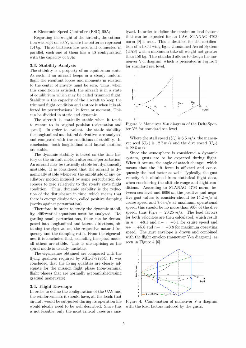
lyzed. In order to define the maximum load factorsthat can be expected for an UAV, STANAG 4703norm [9] is used. This is destined for the certifica-tion of a fixed-wing light Unmanned Aerial System(UAS) with a maximum take-off weight not greaterthan 150 kg. This standard allows to design the ma-neuver V-n diagram, which is presented in Figure 3for standard sea level.
Figure 3: Maneuver V-n diagram of the DeltaSpot-ter V2 for standard sea level.
Where the stall speed (Us) is 6.5m/s, the maneu-ver seed (UA) is 12.7m/s and the dive speed (UD)is 22.5m/s.
Since the atmosphere is considered a dynamicsystem, gusts are to be expected during flight.When it occurs, the angle of attack changes, whichmeans that the lift force is affected and conse-quently the load factor as well. Typically, the gustvelocity u is obtained from statistical flight data,when considering the altitude range and flight con-ditions. According to STANAG 4703 norm, be-tween sea level and 6096m, the positive and nega-tive gust values to consider should be 15.2m/s atcruise speed and 7.6m/s at maximum operationalspeed, this should be no more than 90% of the divespeed, thus VMO = 20.25m/s. The load factorsfor both velocities are then calculated, which resultin n = +8.1 and n− = −6.1 for cruise speed andn+ = +5.8 and n− = −3.8 for maximum operatingspeed. The gust envelope is drawn and combinedwith the flight envelop (maneuver V-n diagram), asseen in Figure 4 [6].
Figure 4: Combination of maneuver V-n diagramwith the load factors induced by the gusts.
5
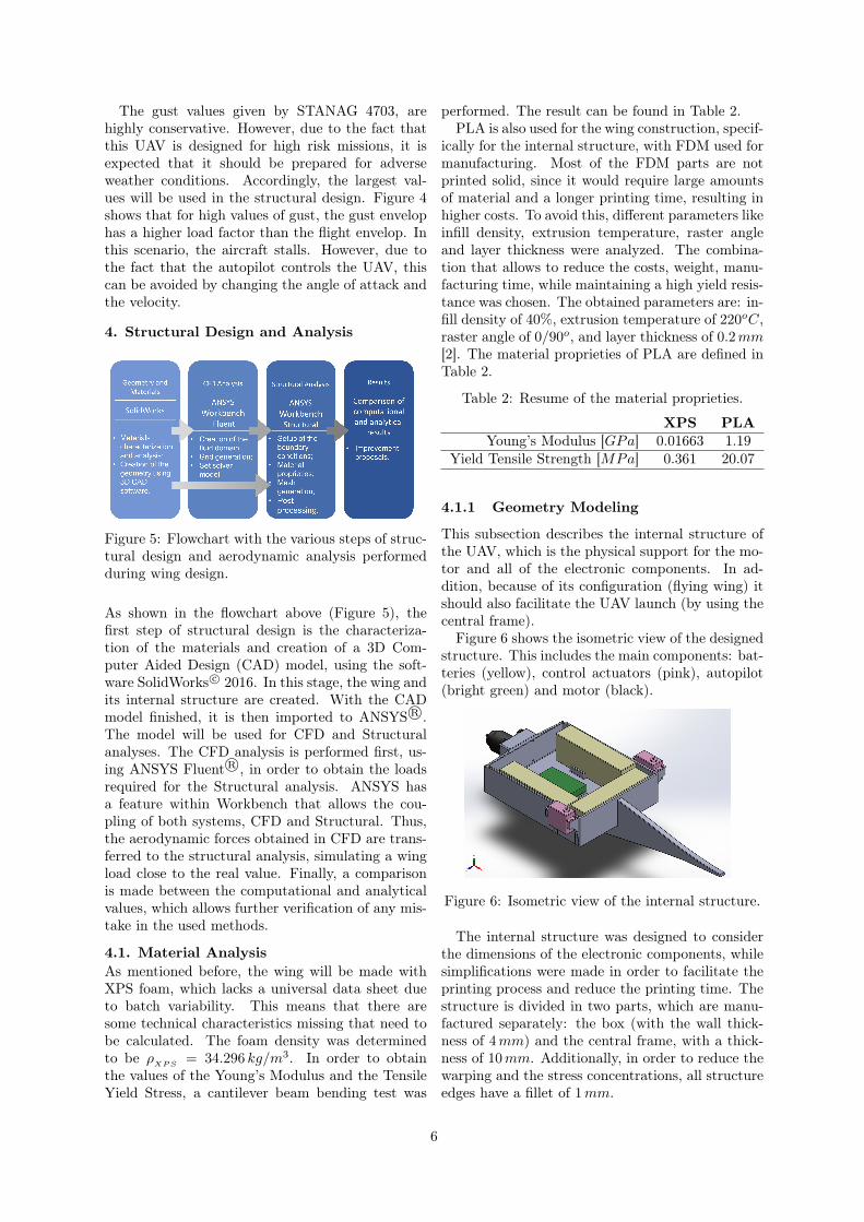
The gust values given by STANAG 4703, arehighly conservative. However, due to the fact thatthis UAV is designed for high risk missions, it isexpected that it should be prepared for adverseweather conditions. Accordingly, the largest val-ues will be used in the structural design. Figure 4shows that for high values of gust, the gust envelophas a higher load factor than the flight envelop. Inthis scenario, the aircraft stalls. However, due tothe fact that the autopilot controls the UAV, thiscan be avoided by changing the angle of attack andthe velocity.
4. Structural Design and Analysis
Figure 5: Flowchart with the various steps of struc-tural design and aerodynamic analysis performedduring wing design.
As shown in the flowchart above (Figure 5), thefirst step of structural design is the characteriza-tion of the materials and creation of a 3D Com-puter Aided Design (CAD) model, using the soft-ware SolidWorks c© 2016. In this stage, the wing andits internal structure are created. With the CADmodel finished, it is then imported to ANSYS R©.The model will be used for CFD and Structuralanalyses. The CFD analysis is performed first, us-ing ANSYS Fluent R©, in order to obtain the loadsrequired for the Structural analysis. ANSYS hasa feature within Workbench that allows the cou-pling of both systems, CFD and Structural. Thus,the aerodynamic forces obtained in CFD are trans-ferred to the structural analysis, simulating a wingload close to the real value. Finally, a comparisonis made between the computational and analyticalvalues, which allows further verification of any mis-take in the used methods.
4.1. Material AnalysisAs mentioned before, the wing will be made withXPS foam, which lacks a universal data sheet dueto batch variability. This means that there aresome technical characteristics missing that need tobe calculated. The foam density was determinedto be ρ
XPS= 34.296 kg/m3. In order to obtain
the values of the Young’s Modulus and the TensileYield Stress, a cantilever beam bending test was
performed. The result can be found in Table 2.PLA is also used for the wing construction, specif-
ically for the internal structure, with FDM used formanufacturing. Most of the FDM parts are notprinted solid, since it would require large amountsof material and a longer printing time, resulting inhigher costs. To avoid this, different parameters likeinfill density, extrusion temperature, raster angleand layer thickness were analyzed. The combina-tion that allows to reduce the costs, weight, manu-facturing time, while maintaining a high yield resis-tance was chosen. The obtained parameters are: in-fill density of 40%, extrusion temperature of 220oC,raster angle of 0/90o, and layer thickness of 0.2mm[2]. The material proprieties of PLA are defined inTable 2.
Table 2: Resume of the material proprieties.
XPS PLAYoung’s Modulus [GPa] 0.01663 1.19
Yield Tensile Strength [MPa] 0.361 20.07
4.1.1 Geometry Modeling
This subsection describes the internal structure ofthe UAV, which is the physical support for the mo-tor and all of the electronic components. In ad-dition, because of its configuration (flying wing) itshould also facilitate the UAV launch (by using thecentral frame).
Figure 6 shows the isometric view of the designedstructure. This includes the main components: bat-teries (yellow), control actuators (pink), autopilot(bright green) and motor (black).
Figure 6: Isometric view of the internal structure.
The internal structure was designed to considerthe dimensions of the electronic components, whilesimplifications were made in order to facilitate theprinting process and reduce the printing time. Thestructure is divided in two parts, which are manu-factured separately: the box (with the wall thick-ness of 4mm) and the central frame, with a thick-ness of 10mm. Additionally, in order to reduce thewarping and the stress concentrations, all structureedges have a fillet of 1mm.
6
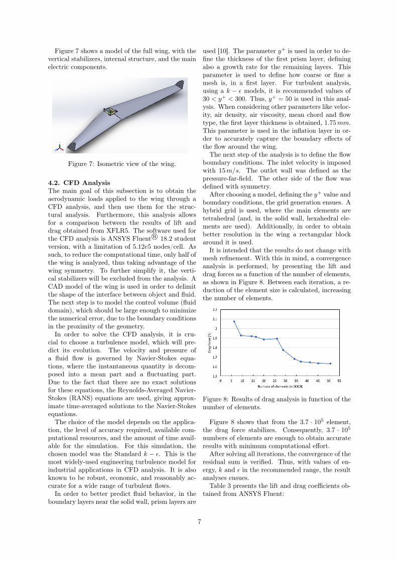
Figure 7 shows a model of the full wing, with thevertical stabilizers, internal structure, and the mainelectric components.
Figure 7: Isometric view of the wing.
4.2. CFD AnalysisThe main goal of this subsection is to obtain theaerodynamic loads applied to the wing through aCFD analysis, and then use them for the struc-tural analysis. Furthermore, this analysis allowsfor a comparison between the results of lift anddrag obtained from XFLR5. The software used forthe CFD analysis is ANSYS Fluent R© 18.2 studentversion, with a limitation of 5.12e5 nodes/cell. Assuch, to reduce the computational time, only half ofthe wing is analyzed, thus taking advantage of thewing symmetry. To further simplify it, the verti-cal stabilizers will be excluded from the analysis. ACAD model of the wing is used in order to delimitthe shape of the interface between object and fluid.The next step is to model the control volume (fluiddomain), which should be large enough to minimizethe numerical error, due to the boundary conditionsin the proximity of the geometry.
In order to solve the CFD analysis, it is cru-cial to choose a turbulence model, which will pre-dict its evolution. The velocity and pressure ofa fluid flow is governed by Navier-Stokes equa-tions, where the instantaneous quantity is decom-posed into a mean part and a fluctuating part.Due to the fact that there are no exact solutionsfor these equations, the Reynolds-Averaged Navier-Stokes (RANS) equations are used, giving approx-imate time-averaged solutions to the Navier-Stokesequations.
The choice of the model depends on the applica-tion, the level of accuracy required, available com-putational resources, and the amount of time avail-able for the simulation. For this simulation, thechosen model was the Standard k − ε. This is themost widely-used engineering turbulence model forindustrial applications in CFD analysis. It is alsoknown to be robust, economic, and reasonably ac-curate for a wide range of turbulent flows.
In order to better predict fluid behavior, in theboundary layers near the solid wall, prism layers are
used [10]. The parameter y+ is used in order to de-fine the thickness of the first prism layer, definingalso a growth rate for the remaining layers. Thisparameter is used to define how coarse or fine amesh is, in a first layer. For turbulent analysis,using a k − ε models, it is recommended values of30 < y+ < 300. Thus, y+ = 50 is used in this anal-ysis. When considering other parameters like veloc-ity, air density, air viscosity, mean chord and flowtype, the first layer thickness is obtained, 1.75mm.This parameter is used in the inflation layer in or-der to accurately capture the boundary effects ofthe flow around the wing.
The next step of the analysis is to define the flowboundary conditions. The inlet velocity is imposedwith 15m/s. The outlet wall was defined as thepressure-far-field. The other side of the flow wasdefined with symmetry.
After choosing a model, defining the y+ value andboundary conditions, the grid generation ensues. Ahybrid grid is used, where the main elements aretetrahedral (and, in the solid wall, hexahedral ele-ments are used). Additionally, in order to obtainbetter resolution in the wing a rectangular blockaround it is used.
It is intended that the results do not change withmesh refinement. With this in mind, a convergenceanalysis is performed, by presenting the lift anddrag forces as a function of the number of elements,as shown in Figure 8. Between each iteration, a re-duction of the element size is calculated, increasingthe number of elements.
Figure 8: Results of drag analysis in function of thenumber of elements.
Figure 8 shows that from the 3.7 · 105 element,the drag force stabilizes. Consequently, 3.7 · 105
numbers of elements are enough to obtain accurateresults with minimum computational effort.
After solving all iterations, the convergence of theresidual sum is verified. Thus, with values of en-ergy, k and ε in the recommended range, the resultanalyses ensues.
Table 3 presents the lift and drag coefficients ob-tained from ANSYS Fluent:
7
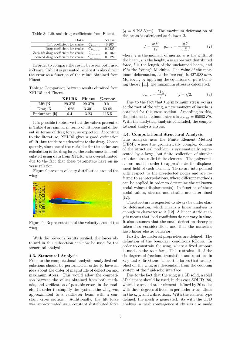
Table 3: Lift and drag coefficients from Fluent.
Data ValueLift coefficient for cruise CLcruise 0.203
Drag coefficient for cruise CDcruise 0.0225Zero lift drag coefficient for cruise CD0cruise
0.0102Induced drag coefficient for cruise CDicruise 0.0124
In order to compare the result between both usedsoftware, Table 4 is presented, where it is also shownthe error as a function of the values obtained fromFluent.
Table 4: Comparison between results obtained fromXFLR5 and Fluent.
XFLR5 Fluent %errorLift [N] 29.375 29.379 0.01Drag [N] 1.628 3.301 50.68
Endurance [h] 6.4 3.23 115.5
It is possible to observe that the values presentedin Table 4 are similar in terms of lift force and differ-ent in terms of drag force, as expected. Accordingto the literature, XFLR5 gives a good estimationof lift, but tends to underestimate the drag. Conse-quently, since one of the variables for the endurancecalculation is the drag force, the endurance time cal-culated using data from XFLR5 was overestimated,due to the fact that these parameters have an in-verse relation.
Figure 9 presents velocity distribution around thewing.
Figure 9: Representation of the velocity around thewing.
With the previous results verified, the forces ob-tained in this subsection can now be used for thestructural analysis.
4.3. Structural AnalysisPrior to the computational analysis, analytical cal-culations should be performed in order to have anidea about the order of magnitude of deflection andmaximum stress. This would allow the compari-son between the values obtained from both meth-ods, and verification of possible errors in the mod-els. In order to simplify the system, the wing wasapproximated to a cantilever beam with a con-stant cross section. Additionally, the lift forcewas approximated as a constant distributed force
(q = 9.793N/m). The maximum deformation ofthe beam is calculated as follows: 2.
I =w i3
12ymax = − q l4
8E I(2)
where, I is the moment of inertia, w is the width ofthe beam, i is the height, q is a constant distributedforce, l is the length of the unclamped beam, andE is the Young’s Modulus. The value of the max-imum deformation, at the free end, is 427.988mm.Moreover, by applying the equations of pure bend-ing theory [11], the maximum stress is calculated:
σmax =M y
I; y = i/2. (3)
Due to the fact that the maximum stress occursat the root of the wing, a new moment of inertia isobtained for this cross section. According to this,the obtained maximum stress is σmax = 65003Pa.With the analytical analysis concluded, the compu-tational analysis ensues.
4.4. Computational Structural AnalysisThis analysis uses the Finite Element Method(FEM), where the geometrically complex domainof the structural problem is systematically repre-sented by a large, but finite, collection of simplersub-domains, called finite elements. The polynomi-als are used in order to approximate the displace-ment field of each element. These are interpolatedwith respect to the preselected nodes and are re-ferred to as interpolations, where different methodscan be applied in order to determine the unknownnodal values (displacements). In function of thesenodal values, stresses and strains are determined[12].
The structure is expected to always be under elas-tic deformation, which means a linear analysis isenough to characterize it [12]. A linear static anal-ysis means that load conditions do not vary in time.It also assumes that the small deflection theory istaken into consideration, and that the materialshave linear elastic behavior.
Firstly, the material proprieties are defined. Thedefinition of the boundary conditions follows. Inorder to constrain the wing, where a fixed supportis used on the root face. This restrains all of thesix degrees of freedom, translation and rotations inx, y and z directions. Thus, the forces that are ap-plied on the wing are descendant from the couplingsystem of the fluid-solid interface.
Due to the fact that the wing is a 3D solid, a solid3D element should be used, in this case SOLID 186,which is a second order element, defined by 20 nodeswith three degrees of freedom per node: translationsin the x, y, and z directions. With the element typedefined, the mesh is generated. As with the CFDanalysis, a mesh convergence study was also made
8
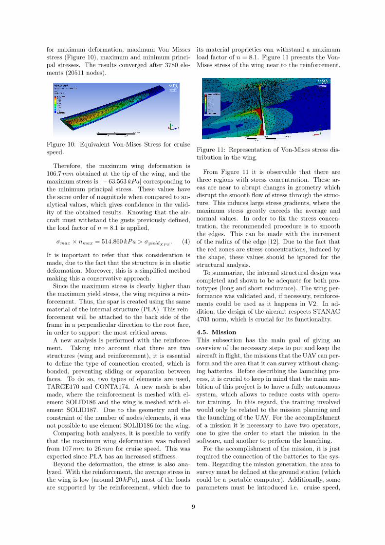
for maximum deformation, maximum Von Missesstress (Figure 10), maximum and minimum princi-pal stresses. The results converged after 3780 ele-ments (20511 nodes).
Figure 10: Equivalent Von-Mises Stress for cruisespeed.
Therefore, the maximum wing deformation is106.7mm obtained at the tip of the wing, and themaximum stress is |−63.563 kPa| corresponding tothe minimum principal stress. These values havethe same order of magnitude when compared to an-alytical values, which gives confidence in the valid-ity of the obtained results. Knowing that the air-craft must withstand the gusts previously defined,the load factor of n = 8.1 is applied,
σmax × nmax = 514.860 kPa > σyieldXPS . (4)
It is important to refer that this consideration ismade, due to the fact that the structure is in elasticdeformation. Moreover, this is a simplified methodmaking this a conservative approach.
Since the maximum stress is clearly higher thanthe maximum yield stress, the wing requires a rein-forcement. Thus, the spar is created using the samematerial of the internal structure (PLA). This rein-forcement will be attached to the back side of theframe in a perpendicular direction to the root face,in order to support the most critical areas.
A new analysis is performed with the reinforce-ment. Taking into account that there are twostructures (wing and reinforcement), it is essentialto define the type of connection created, which isbonded, preventing sliding or separation betweenfaces. To do so, two types of elements are used,TARGE170 and CONTA174. A new mesh is alsomade, where the reinforcement is meshed with el-ement SOLID186 and the wing is meshed with el-ement SOLID187. Due to the geometry and theconstraint of the number of nodes/elements, it wasnot possible to use element SOLID186 for the wing.
Comparing both analyses, it is possible to verifythat the maximum wing deformation was reducedfrom 107mm to 26mm for cruise speed. This wasexpected since PLA has an increased stiffness.
Beyond the deformation, the stress is also ana-lyzed. With the reinforcement, the average stress inthe wing is low (around 20 kPa), most of the loadsare supported by the reinforcement, which due to
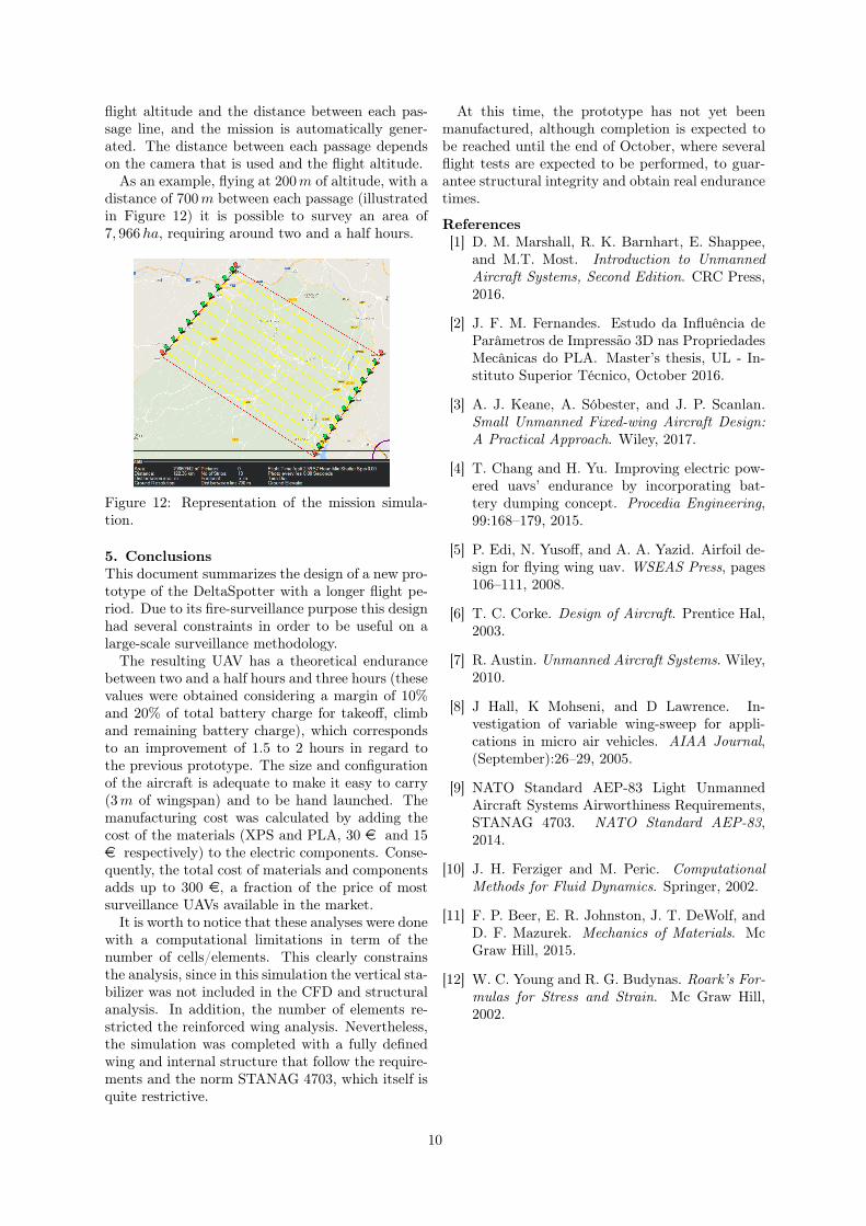
its material proprieties can withstand a maximumload factor of n = 8.1. Figure 11 presents the Von-Mises stress of the wing near to the reinforcement.
Figure 11: Representation of Von-Mises stress dis-tribution in the wing.
From Figure 11 it is observable that there arethree regions with stress concentration. These ar-eas are near to abrupt changes in geometry whichdisrupt the smooth flow of stress through the struc-ture. This induces large stress gradients, where themaximum stress greatly exceeds the average andnormal values. In order to fix the stress concen-tration, the recommended procedure is to smooththe edges. This can be made with the incrementof the radius of the edge [12]. Due to the fact thatthe red zones are stress concentrations, induced bythe shape, these values should be ignored for thestructural analysis.
To summarize, the internal structural design wascompleted and shown to be adequate for both pro-totypes (long and short endurance). The wing per-formance was validated and, if necessary, reinforce-ments could be used as it happens in V2. In ad-dition, the design of the aircraft respects STANAG4703 norm, which is crucial for its functionality.
4.5. MissionThis subsection has the main goal of giving anoverview of the necessary steps to put and keep theaircraft in flight, the missions that the UAV can per-form and the area that it can survey without chang-ing batteries. Before describing the launching pro-cess, it is crucial to keep in mind that the main am-bition of this project is to have a fully autonomoussystem, which allows to reduce costs with opera-tor training. In this regard, the training involvedwould only be related to the mission planning andthe launching of the UAV. For the accomplishmentof a mission it is necessary to have two operators,one to give the order to start the mission in thesoftware, and another to perform the launching.
For the accomplishment of the mission, it is justrequired the connection of the batteries to the sys-tem. Regarding the mission generation, the area tosurvey must be defined at the ground station (whichcould be a portable computer). Additionally, someparameters must be introduced i.e. cruise speed,
9
flight altitude and the distance between each pas-sage line, and the mission is automatically gener-ated. The distance between each passage dependson the camera that is used and the flight altitude.
As an example, flying at 200m of altitude, with adistance of 700m between each passage (illustratedin Figure 12) it is possible to survey an area of7, 966ha, requiring around two and a half hours.
Figure 12: Representation of the mission simula-tion.
5. ConclusionsThis document summarizes the design of a new pro-totype of the DeltaSpotter with a longer flight pe-riod. Due to its fire-surveillance purpose this designhad several constraints in order to be useful on alarge-scale surveillance methodology.
The resulting UAV has a theoretical endurancebetween two and a half hours and three hours (thesevalues were obtained considering a margin of 10%and 20% of total battery charge for takeoff, climband remaining battery charge), which correspondsto an improvement of 1.5 to 2 hours in regard tothe previous prototype. The size and configurationof the aircraft is adequate to make it easy to carry(3m of wingspan) and to be hand launched. Themanufacturing cost was calculated by adding thecost of the materials (XPS and PLA, 30 e and 15e respectively) to the electric components. Conse-quently, the total cost of materials and componentsadds up to 300 e, a fraction of the price of mostsurveillance UAVs available in the market.
It is worth to notice that these analyses were donewith a computational limitations in term of thenumber of cells/elements. This clearly constrainsthe analysis, since in this simulation the vertical sta-bilizer was not included in the CFD and structuralanalysis. In addition, the number of elements re-stricted the reinforced wing analysis. Nevertheless,the simulation was completed with a fully definedwing and internal structure that follow the require-ments and the norm STANAG 4703, which itself isquite restrictive.
At this time, the prototype has not yet beenmanufactured, although completion is expected tobe reached until the end of October, where severalflight tests are expected to be performed, to guar-antee structural integrity and obtain real endurancetimes.
References[1] D. M. Marshall, R. K. Barnhart, E. Shappee,
and M.T. Most. Introduction to UnmannedAircraft Systems, Second Edition. CRC Press,2016.
[2] J. F. M. Fernandes. Estudo da Influência deParâmetros de Impressão 3D nas PropriedadesMecânicas do PLA. Master’s thesis, UL - In-stituto Superior Técnico, October 2016.
[3] A. J. Keane, A. Sóbester, and J. P. Scanlan.Small Unmanned Fixed-wing Aircraft Design:A Practical Approach. Wiley, 2017.
[4] T. Chang and H. Yu. Improving electric pow-ered uavs’ endurance by incorporating bat-tery dumping concept. Procedia Engineering,99:168–179, 2015.
[5] P. Edi, N. Yusoff, and A. A. Yazid. Airfoil de-sign for flying wing uav. WSEAS Press, pages106–111, 2008.
[6] T. C. Corke. Design of Aircraft. Prentice Hal,2003.
[7] R. Austin. Unmanned Aircraft Systems. Wiley,2010.
[8] J Hall, K Mohseni, and D Lawrence. In-vestigation of variable wing-sweep for appli-cations in micro air vehicles. AIAA Journal,(September):26–29, 2005.
[9] NATO Standard AEP-83 Light UnmannedAircraft Systems Airworthiness Requirements,STANAG 4703. NATO Standard AEP-83,2014.
[10] J. H. Ferziger and M. Peric. ComputationalMethods for Fluid Dynamics. Springer, 2002.
[11] F. P. Beer, E. R. Johnston, J. T. DeWolf, andD. F. Mazurek. Mechanics of Materials. McGraw Hill, 2015.
[12] W. C. Young and R. G. Budynas. Roark’s For-mulas for Stress and Strain. Mc Graw Hill,2002.
10