energy aware aerial surveillance for a long endurance ... · energy aware aerial surveillance for a...
TRANSCRIPT

Energy Aware Aerial Surveillance for a Long Endurance
Solar-Powered UAV
Saghar Hosseini∗, Mehran Mesbahi†
William E. Boeing Department of Aeronautics and Astronautics,
University of Washington, Seattle, WA 98195
In this paper, the energy optimal trajectories for Unmanned Aerial Vehicles (UAV) surveillanceare explored. The main objective is to have maximum sensor coverage range while maintaining aperpetual ight. A solar powered UAV is used in this paper that is equipped with photovoltaiccells mounted on its wing and rechargeable batteries. The photovoltaic cells generate solar energybased on the position of the sun, attitude of the UAV, and sky clarity. The vehicle tries to optimizethe energy storage in the batteries during the day. However, the sensor resolution diminishes dueto altitude gain. A model for optimal coverage, path planning, and power allocation in a solarpowered UAV is proposed and the corresponding simulation results are presented.
Nomenclature
φ Bank angle, rad L Lift force, N
ψ Heading angle, rad CL Coecient of lift
γ Flight path angle, rad D Drag force, N
a Azimuth of the sun, rad CD Coecient of drag
e Elevation of the sun, rad CD0 Parasitic drag coecient
i Incidence angle of sun rays, rad T Thrust force, N
θ Sensor eld of view angle, rad ε Oswald eciency factor
c Sensor coverage range, m g Gravitational acceleration, m/s2
x x coordinate in a at Earth-xed reference frame, m ρ Air density, kg/m3
y y coordinate in a at Earth-xed reference frame, m Pbatt Battery pack output power, watt
z z coordinate in a at Earth-xed reference frame, m Q Battery pack charge capacity, Ah
V Flight speed, m/s Voc Battery pack open circuit voltage, V olt
nv Vertical load factor R Battery pack internal resistance, ohm
nh Horizontal load factor SOC Battery pack state of charge, %
ηprop Eciency of the propeller PTot Total power, watt
ηsol Eciency of the solar cells Psd Solar spectral density, watt/m2
I. Introduction
Long endurance Unmanned Aerial Vehicles (UAVs) have a wide range of applications in scientic research, cropand forestry re monitoring, search and rescue, remote sensing, mapping, and atmospheric sensing missions. Oneway to extend the duration of UAV ight is to change the conguration of aircraft i.e. its wings1 or propulsion system. In this context, hybrid propulsion systems with several power sources such as solar cells, fuel cells, and batterieshave been proposed.2,3 Another approach to increase the ight duration is to take advantage of energy available inthe surrounding atmosphere in the form of wind gusts and thermals. There is extensive literature on path planningand trajectory optimization for soaring ight.46 In addition, solar energy is a favorable candidate to collect energy
∗Graduate Student, William E. Boeing Department of Aeronautics and Astronautics, University of Washington, Seattle, WA. Email:[email protected]†Professor, William E. Boeing Department of Aeronautics and Astronautics, University of Washington, Seattle, WA. Email: mes-
1 of 13
American Institute of Aeronautics and Astronautics
from the environment and power the UAVs. In pursuit of this goal, several solar powered UAVs have been builtand own since 1974. The latest solar powered UAV, Solar Eagle developed by Boeing, has an approximately 400 ftwingspan and is expected to be launched in 2014 to y at high altitudes with an endurance of ve years.
Provided with long endurance UAVs, the surveillance problem in aerial vehicles is becoming feasible and is aninteresting research topic.711 However, the energy eciency aspect of this problem has not been addressed at largeby scientic community. Mei et al.12 proposed an ecient algorithm for deployment of multiple mobile robotsthat take into account energy and timing constraints, and explores the surveillance problem in ground robots. Anendurance constraint is also considered in the aerial surveillance problem. Nigam et al.13 added the enduranceconstraint to the control of multiple quad-rotor vehicles in order to achieve persistent surveillance. Moreover, Sujitand Ghose14 presented a search algorithm for UAVs with limited fuel. These works does not deal with energyconsumption constraint directly and use a xed ight time to represent this constraint.
In energy optimal surveillance, the solar powered UAV employs optimal strategies to maximize energy harvestingand sensor coverage range during the ight. The energy optimized path planning problem for a solar powered UAVhas been studied before.1519 For example, in our previous work,15 we used model reduction techniques to investigatethe optimal path planning and energy allocation problem for a single UAV in 3D space. The objective function waschosen as the nal state of charge of the battery pack to maximize the energy stored on the UAV.
In this paper, we examine the optimal energy and coverage surveillance for a duration of 24 hours of a singlesolar powered UAV in 3D space. While maximizing the sensor coverage range for better observation, the secondaryobjective of the vehicle is to maximize the total energy stored in batteries at the end of the duration. During themission, the aircraft must also satisfy boundary conditions and feasibility constraints on its states. Finally, a directoptimization method is used to solve the optimal energy surveillance problem and the results are compared with theoptimal coverage surveillance problem.
The paper is organized as follows. §II presents the models for aircraft kinematics, power subsystems, and sensors.In §III, the optimal control problem formulations for two dierent objective functions are presented and a solutionstrategy based on nonlinear programming is discussed. Numerical results for a sample UAV path planning areinvestigated and their interpretation is described in §IV. Finally, §V presents the concluding remarks followed byfuture research.
II. Background and Model
This section presents a brief background on the models for the aircraft kinematics, electric components, andsensor coverage range used in this paper. The major power systems considered in the solar UAV are the solar cells,electric motor, and rechargeable batteries. The solar UAV power system generally contains other units of whichpower consumption is negligible compared to the three major components mentioned above.
A. Sensor Coverage Range
The sensor coverage range and resolution is modeled as a linear function of altitude as mentioned in Ref.7 The sensorhas a constant eld of view angle and its coverage range increases as the UAV gain altitude. Nevertheless, the sensorresolution diminishes at high altitudes which is modeled as a linear function.
c(z) =
z tan θ if 0 ≤ z ≤ hmaxhmax tan θ − hmax tan θ
h0−hmax(z − hmax) if hmax ≤ z ≤ h0
, (1)
where c and z are the coverage range and altitude respectively. The sensor eld of view angle is represented byθ. hmax is the altitude at which the sensor has maximum coverage range. Also, h0 represents the altitude at whichthe sensor resolution is not appropriate for the aerial surveillance and without loss of generality we can assume thecoverage range is zero at z ≥ h0. The coverage range of a sensor with a given eld of view angle of θ is also shownin Fig. 1.
2 of 13
American Institute of Aeronautics and Astronautics

Figure 1. The sensor coverage range on the X − Y plane.
The values of sensor parameters hmax, h0, and θ used in numerical simulations are given in the appendix.
B. Electric Motor
Solar powered UAVs usually have an electric engine attached to a propeller. The output power consumed by theengine is dened as
PEng =TV
ηprop, (2)
where T is the engine thrust and ηprop is the eciency of the propeller. The available thrust is limited to a maximumvalue, Tmax, which is predetermined by the characteristics of the aircraft engine.
C. Solar Cells
The power gained from photovoltaic cells is modeled based on the incidence angle with the sub, i, and solar cellparameters17
PSun = ηsolPsdS cos i, (3)
where ηsol is the eciency of the photovoltaic cells, S is the solar cell area, and Psd is the solar spectral density.The incidence angle i depends upon the sun position in the sky and the UAV Euler angles. The sun position can bedescribed by its azimuth and elevation angles as a function of time.20 For example, the elevation and azimuth anglesof the sun on a typical spring day in San Diego, California, is depicted in Fig. 2.
3 of 13
American Institute of Aeronautics and Astronautics

0 5 10 15 20 25−1
0
1
2
3
4
5
6
Time (hr)
Elevation angle of the sunAzimuth angle of the sun
Figure 2. The azimuth and elevation angles of the sun on April 1st, 2012, in San Diego, CA. The simulation timestarts at 1am and ends at midnight.
The inner product of the aircraft-xed vertical axis and the sun position vector expressed in the aircraft-xedframe yields cosine function for the incidence angle i,
cos i = sTA.z, (4)
where sA is the unit vector to the sun in the Earth-xed frame and z is the aircraft-xed vertical axis. The unitvector to the sun in aircraft-xed frame can be expressed as
sA(t) = R1(φ)R2(γ)R3(ψ)sE(t). (5)
The vector sE in Eq. 5 is the unit vector to the Sun in the Earth-xed frame dened as sE(t) = [cos e(t) cos a(t) cos e(t) sin a(t) sin e(t)]Tand
the R1, R2, and R3 are rotation matrices about the rst, second, and third axis, respectively. Figure 3 illustratesthe Euler angles and the unit vector to the Sun in the Earth-xed frame.
x
y
z
X
Y
Z
Earth fixed
Body
!
"
#
$
Figure 3. (X,Y, Z) represents the Earth-xed frame and (x, y, z) represents the aircraft-xed frame. The sun angles,i.e., a, e, are dened in the Earth-xed frame and UAV Euler angles, i.e., γ, φ, and ψ are expressed in aircraft-xedframe.
4 of 13
American Institute of Aeronautics and Astronautics
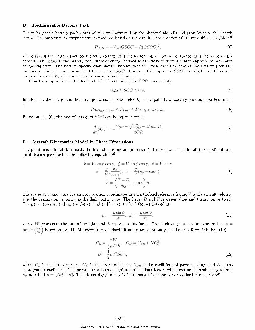
D. Rechargeable Battery Pack
The rechargeable battery pack stores solar power harvested by the photovoltaic cells and provides it to the electricmotor. The battery pack output power is modeled based on the circuit representation of lithium-sulfur cells (Li-S)21
PBatt = −VOCQ ˙SOC −R(Q ˙SOC)2, (6)
where VOC is the battery pack open circuit voltage, R is the battery pack internal resistance, Q is the battery packcapacity, and SOC is the battery pack state of charge dened as the ratio of current charge capacity to maximumcharge capacity. The battery specication sheet22 implies that the open circuit voltage of the battery pack is afunction of the cell temperature and the value of SOC. However, the impact of SOC is negligible under normaltemperature and VOC is assumed to be constant in this paper.
In order to optimize the limited cycle life of batteries21, the SOC must satisfy
0.25 ≤ SOC ≤ 0.9. (7)
In addition, the charge and discharge performance is bounded by the capability of battery pack as described in Eq.8
PBatt0,Charge ≤ PBatt ≤ PBatt0,Discharge. (8)
Based on Eq. (6), the rate of charge of SOC can be represented as
d
dtSOC = −
VOC −√V 2OC − 4PBattR
2QR. (9)
E. Aircraft Kinematics Model in Three Dimensions
The point mass aircraft kinematics in three dimensions are presented in this section. The aircraft ies in still air andits states are governed by the following equations23
x = V cosψ cos γ, y = V sinψ cos γ, z = V sin γ
ψ =g
V(nh
cos γ), γ =
g
V(nv − cos γ) (10)
V =
(T −Dmg
− sin γ
)g.
The states x, y, and z are the aircraft position coordinates in a Earth-xed reference frame, V is the aircraft velocity,ψ is the heading angle, and γ is the ight path angle. The forces D and T represent drag and thrust, respectively.The parameters nv and nh are the vertical and horizontal load factors dened as
nh =L sinφ
W, nv =
L cosφ
W, (11)
where W represents the aircraft weight, and L represents lift force. The bank angle φ can be expressed as φ =
tan−1(nh
nv
)based on Eq. 11. Moreover, the standard lift and drag equations gives the drag force D in Eq. (10)
CL =nW
12ρV
2S, CD = CD0 +KC2
L
D =1
2ρV 2SCD, (12)
where CL is the lift coecient, CD is the drag coecient, CD0 is the coecient of parasitic drag, and K is theaerodynamic coecient. The parameter n is the magnitude of the load factor, which can be determined by nh andnv such that n =
√n2h + n2v. The air density ρ in Eq. 12 is estimated from the U.S. Standard Atmosphere.24
5 of 13
American Institute of Aeronautics and Astronautics

III. Problem Statement
In this section, the problem of energy optimal trajectories for surveillance between two given locations is formu-lated as an optimal control problem with a set of constraints. The cost function in the optimal coverage problem isthe cumulative sum of sensor coverage range over time.
C(tf ) =
ˆ tf
t0
c(z)dt, (13)
where c(z) is the coverage range given in Eq. 1. The nal state of charge SOC(tf ) in battery pack is also used
as the cost function for energy optimal path planning.15 The state variables [x, y, z, ψ, γ, V, SOC,C]Tand control
variables [nv, nh, T, PBatt]Tare constrained to satisfy the aircraft kinematics in Eq. (10), battery discharge rate in
Eq. (9), sensor coverage range in Eq. 1, and boundary conditions. The mission is to y between the specied initialand nal positions during the time interval [t0, tf ].
Several constraints on state and control variables are also introduced based on limited UAV maneuverability,structural capability, solar sources, and battery capacity. The UAV velocity is bounded by Vstall and Vmax whichare the stall and maximum feasible velocity of the aircraft, respectively. The rate of change of heading angle ψ hasto satisfy |ψ| ≤ Ψ in order to generate a smooth trajectory where Ψ is the maximum changing rate of the headingangle. Powered ight requires the total power PTot to be positive, which means the power consumption must beless than or equal to power generated by solar cells and/or the battery pack. Based on the above description, theoptimal energy surveillance problem can be formulated as:
max(nv,nh,T,PBatt)
C(tf ) + SOC(tf ) (14)
subject to
x = V cosψ cos γ, y = V sinψ cos γ, z = V sin γ
ψ =g
V(nh
cos γ), γ =
g
V(nv − cos γ)
V =
(T −Dmg
− sin γ
)g (15)
˙SOC = −VOC −
√V 2OC − 4PBattR
2QR
C = c(z)
and
||ψ| ≤ Ψ, |γ| ≤ π
2,
Vstall ≤ V ≤ Vmax,0 ≤ T ≤ Tmax,
0.25 ≤ SOC ≤ 0.9, (16)
|nv| ≤ nvmax, |nh| ≤ nhmax ,
PBatt0,Charge ≤ PBatt ≤ PBatt0,DischargePTot=PSun + PBatt − PEng ≥ 0,
with boundary conditions:
[x(t0), y(t0), z(t0), ψ(t0), γ(t0), V (t0), SOC(t0)]T =
[x0, y0, z0, ψ0, γ0, V0, SOC0]T
[x(tf ), y(tf ), z(tf )]T = [xf , yf , zf ]T , (17)
6 of 13
American Institute of Aeronautics and Astronautics

IV. Nonlinear Programming Approach
A. Nonlinear Programming Method
The optimal control problem presented in Eq. (14) through Eq. (17) is a complex nonlinear optimization problemand large in dimension. The general approach to solve these types of problems is the direct collocation (DC) method.DC is an approximate method that discretizes a continuous solution and uses linear interpolation to satisfy thedierential equations. This method transforms the optimal control problem into a nonlinear programming problem(NLPP) and the solution is in terms of innitely many values of state and control variables.
The nonlinear programming (NLP) solver used to solve our optimization problem is based on a sequential quadra-ture programming (SQP) algorithm called NPSOL.25,26 NPSOL can be used to solve problems such as minimizinga performance index subject to constraints on individual state and/or control variables. Since the mission time of24-hour is long (86400 seconds), some of the state and control variables need to be scaled to make the solutionconverge faster and also avoid the singularities that may occur in estimating the underlying Hessian matrices.
B. Simulation Results using NLP Method
The simulation results for the two optimal control problems are illustrated in this section and their correspondingsensor coverage and energy storage are compared. The boundary conditions are provided in Table 1. The UAVstarts from the origin with zero heading and ight path angles and returns to its initial location after 24 hours. Themission endurance is discretized into 24 nodes representing each hour during one day and night. This large time stepsimplies the optimization problem as well as providing fast convergence and smooth trajectories.
Table 1. Boundary conditions
States Values
[x0, y0, z0] (km) [0, 0, 0]
[ψ0, γ0] (rad) [0, 0]
V0 (m/s) Vmin
SOC0 0.9
[xf , yf , zf ] (km) [0, 0, 0]
C. Optimal Coverage Surveillance Problem
Figures 9 through 12 illustrate the numerical results for optimal coverage surveillance with the cost function speciedin Eq. 13 where the energy storage in the system is not optimized. Figure 4(a) and Fig. 4(b) present the optimaltrajectory in 3D space as well as its projection on the X − Y plane. The optimal trajectory is relatively smoothbased on the facts that the time step chosen in algorithm is 1 hour and the heading rate of change is constrained inthe optimization problem.Regarding the velocity and altitude prole in Figs. 5(a) and 5(b), the UAV velocity during the ight has small scaleuctuation around 10 m/s. In addition, the UAV starts at zero altitude and reaches z ≈ 500m altitude. The aircraftstays at that altitude at which the sensor coverage range is at its maximum value. Although, the goal of the UAVis to achieve maximum sensor coverage range, it has to maintain the powered ight. Therefore, the UAV climbs upto higher altitudes (z ≈ 2km) to gain potential energy and spend this energy by soaring during night.Figure 6 shows the smooth transitions of attitude angles of the UAV during trajectory. Figure 6(a) implies that thesolar harvesting reaches maximum at noon and is zero between sunset and sunrise. Besides, the ight path angle γshown in Fig. 6(c) is very small during the ight. It is noted in Fig. 6(c), the bank angle φ is approximately zeroduring the mission which refers to the fact that the aerodynamic drag value is at its local minimum when φ = 0.15
Maintaining a powered ight is one of the optimization constraints as described in Eq. 16. Therefore, the powerallocation strategy is illustrated in Fig. 7 for further investigation. Figure 7(a) indicates the time history of the SOCand Fig. 7(b) represents the power allocation during the trajectory. It is shown that the battery pack is chargedduring the day while the UAV uses solar power to supply the required power.
Finally, the coverage range of the UAV sensor is presented in Fig. 8, which demonstrates the UAV tendency tostay at amax.
7 of 13
American Institute of Aeronautics and Astronautics

−1000
100200
−200
0
200
400−1
0
1
2
3
y (km)x (km)
z (k
m)
−0.5 0 0.5 1 1.5−0.5
0
0.5
1
1.5
2
2.5
y (1
00km
)
x (100km)
(a) (b)
Figure 4. The optimal trajectory in (X −Y −Z) space (a), and the X −Y plane (b) are depicted in these gures for theoptimal coverage surveillance problem.
0 5 10 15 20 257
8
9
10
11
12
13
14
15
V (
m/s
)
time (hr)0 5 10 15 20 25
0
0.5
1
1.5
2
2.5
3
3.5
4
z (k
m)
time (hr)
(a) (b)
Figure 5. (a) The UAV velocity during the trajectory, and (b) the altitude of UAV as a function of time are shownfor the optimal coverage surveillance problem.
8 of 13
American Institute of Aeronautics and Astronautics

0 5 10 15 20 25−150
−100
−50
0
50
100
150
200
time (hr)
ψ &
i (d
eg)
ψi
0 5 10 15 20 25−1
−0.5
0
0.5
1
time (hr)
φ(de
g)
0 5 10 15 20 25−3
−2
−1
0
1
2
3
γ (d
eg)
time (hr)
(a) (b) (c)
Figure 6. The aircraft attitude for the optimal coverage surveillance problem is represented by (a) the heading angle,ψ, sun incidence angle, i, (b) bank angle, φ, (c) and ight path angle, γ. The time span is from 1am to midnight ofApril 1, 2012.
0 5 10 15 20 25
0.4
0.5
0.6
0.7
0.8
0.9
1
SO
C
time (hr)0 5 10 15 20 25
−40
−20
0
20
40
60
80
100
time (hr)
Pow
er (
wat
t)
PBatt
PSun
PEng
(a) (b)
Figure 7. (a) Presents the SOC of the battery pack and (c) shows the optimal power allocation during the optimaltrajectory for the optimal coverage surveillance problem.
0 5 10 15 20 250
50
100
150
200
250
300
c (m
)
time (hr)
Figure 8. Sensor coverage range during the optimal trajectory for the optimal coverage surveillance problem.
9 of 13
American Institute of Aeronautics and Astronautics

The optimal coverage cost and nal SOC in this scenario are
C(tf ) = 16226km, SOC(tf ) = 0.383. (18)
D. Optimal Energy Surveillance Problem
The objective function of the optimal energy surveillance problem is to maximize both the sensor coverage range andthe nal state of the charge for the battery pack which represents the energy stored in the system. The objectivefunction for this optimal control problem is expressed in Eq. 14. The optimal trajectory and its velocity proleshown in Figs. 9 and 10 have slightly dierent properties than the optimal coverage problem results. In this case,the energy storage in the system has an important contribution to cost function. Therefore, the UAV climbs higher(z ≈ 3 km) in order to harvest more potential energy. The attitude of the UAV is shown by its Euler angles in Fig.11. The Euler angles have also similar proles as in the optimal coverage surveillance problem.
Moreover, the optimal power allocation strategy is shown in Fig. 12. Figure 12(a) indicates the time history ofthe SOC status from the optimal power allocation output. The SOC prole suggests that the rechargeable batterypack recovers most of its initial state of charge allowing the UAV to resume its operation the next day. The engineinput power, as well as output power form battery pack and solar cells, are depicted in Fig. 12(b). It demonstrateshow the engine operates during the early hours of the mission when UAV performs level ight at low altitude. Theamount of power at this stage is approximately equivalent to the minimum power required at that altitude. Inaddition, the solar power from the sun compensates for both recharging the battery and supplying enough power formaintaining powered ight during the day. Notice in Fig. 12(b) that the total power PTot in (16) is non-negative atall time nodes satisfying the powered ight constraint. Lastly, the coverage range of UAV sensor is presented in Fig.13 which has approximately the same prole as in the optimal coverage surveillance result.
−1000
100200
−200
0
200
4000
1
2
3
4
y (km)x (km)
z (k
m)
−0.5 0 0.5 1 1.5 2−1
−0.5
0
0.5
1
1.5
2
2.5
y (1
00km
)
x (100km)
(a) (b)
Figure 9. The optimal trajectory in X − Y − Z space (a), and the X − Y plane (b) are depicted in these gures for theoptimal energy surveillance problem.
10 of 13
American Institute of Aeronautics and Astronautics

0 5 10 15 20 257
8
9
10
11
12
13
14
15
V (
m/s
)
time (hr)0 5 10 15 20 25
0
0.5
1
1.5
2
2.5
3
3.5
4
z (k
m)
time (hr)
(a) (b)
Figure 10. The UAV velocity during the trajectory (a), and the altitude of UAV as a function of time (b) are shownin this gure for the optimal energy surveillance problem.
0 5 10 15 20 25−200
−150
−100
−50
0
50
100
150
200
time (hr)
ψ &
i (d
eg)
ψi
0 5 10 15 20 25−1
−0.5
0
0.5
1
time (hr)
φ(de
g)
0 5 10 15 20 25−3
−2
−1
0
1
2
3
γ (d
eg)
time (hr)
(a) (b) (c)
Figure 11. The aircraft attitude for the optimal energy surveillance problem is represented by (a) heading angle, ψ,Sun incidence angle, i, (b) bank angle, φ, (c) and ight path angle, γ. The time span is from 1am to midnight of April1, 2012.
0 5 10 15 20 25
0.4
0.5
0.6
0.7
0.8
0.9
1
SO
C
time (hr)0 5 10 15 20 25
−40
−20
0
20
40
60
80
100
time (hr)
Pow
er (
wat
t)
PBatt
PSun
PEng
(a) (b)
Figure 12. Figure (a) presents the SOC of the battery pack and gure (b) shows the optimal power allocation duringthe optimal trajectory for the optimal energy surveillance problem.
11 of 13
American Institute of Aeronautics and Astronautics

0 5 10 15 20 250
50
100
150
200
250
300
c (m
)
time (hr)
Figure 13. Sensor coverage range during the optimal trajectory for the optimal energy surveillance problem.
The optimal coverage cost and nal SOC in this scenario are
C(tf ) = 16372km, SOC(tf ) = 0.706. (19)
From Eqs. 18 and 19 it is noted that the coverage range cost function C(tf ) is slightly less than its value for theenergy optimal surveillance problem. Moreover, the nal SOC of the battery pack is improved by %84 which impliesthat the UAV can achieve a local optimal coverage while optimizing its energy storage. This property can also beused to design perpetual surveillance mission.
V. Conclusion
A simple model is proposed to formulate the optimal energy surveillance problem for a solar-powered UAV in3D space. In this model, the sensor capabilities and electrical models are integrated with the aircraft kinematicswhen solving the optimization problem. The objective function for an optimal coverage surveillance problem isdened as the cumulative sum of coverage range over time. Periodic boundary conditions were considered for thenumerical simulations and optimal solutions using nonlinear programming were obtained. The solutions providecomplete information on the trajectory and power allocation strategy of the UAV. It was noted from the simulationresults that the UAV mission is divided into three phases; level ight, climb, and descend. In the optimal energysurveillance problem, the nal state of charge of the battery pack is included in the objective function. By comparingthe simulation results for these two optimal control problems, it was shown that the energy stored in the UAV isoptimized while keeping the same coverage range prole in the energy optimal surveillance problem. In addition, thetrajectory properties are similar in these two cases. The altitude and SOC proles suggest that the most eectivecontribution to saving energy is the potential energy harvested during climb phase.
This paper is an elementary step towards designing trajectories for long endurance solar powered UAVs whichrequires further investigations. The future research will focus on thermal soaring and the eect of wind gust on theUAV trajectory. Cooperative aerial surveillance and developing simple convex models to simplify this problem arealso other problems which are appealing to explore.
References
1Meyer, J., du Plessis, J., Ellis, P., and Clark, W., Design considerations for a low altitude long endurance solar powered unmannedaerial vehicle, Piscataway, NJ, USA, 2007//, pp. 1 6, solar powered unmanned aerial vehicle;low altitude long endurance unmannedaerial vehicle;low altitude long endurance ight;.
2Capata, R., Marino, L., and Sciubba, E., A hybrid propulsion system for a high-endurance UAV: Conguration selection andaerodynamic study, Vol. 11, Denver, CO, United states, 2011, pp. 767 774.
3Chiesa, S., Farfaglia, S., Fioriti, M., and Viola, N., Design of all electric secondary power system for future advanced mediumaltitude long endurance unmanned aerial vehicles, Proceedings of the Institution of Mechanical Engineers, Part G: Journal of AerospaceEngineering, Vol. 226, No. 10, 2012, pp. 1255 1270.
4Akos, Z., Nagy, M., Leven, S., and Vicsek, T., Thermal Soaring Flight of Birds and Unmanned Aerial Vehicles, Bioinspiration& Biomimetics, Vol. 5, No. 4, 2010/12/, pp. 045003 (12 pp.) .
5Langelaan, J. W., Long distance/duration trajectory optimization for small UAVs, Vol. 4, Hilton Head, SC, United states, 2007,pp. 3654 3667.
12 of 13
American Institute of Aeronautics and Astronautics

6Kagabo, W. and Kolodziej, J., Trajectory determination for energy ecient autonomous soaring, American Control Conference(ACC), 2011 , 29 2011-july 1 2011, pp. 4655 4660.
7Acevedo, J. J., Arrue, B. C., Maza, I., and Ollero, A., Cooperative large area surveillance with a team of aerial mobile robots forlong endurance missions, Journal of Intelligent and Robotic Systems: Theory and Applications, Vol. 70, No. 1-4, 2013, pp. 329 345.
8Doitsidis, L., Weiss, S., Renzaglia, A., Achtelik, M. W., Kosmatopoulos, E., Siegwart, R., and Scaramuzza, D., Optimal surveillancecoverage for teams of micro aerial vehicles in GPS-denied environments using onboard vision, Autonomous Robots, Vol. 33, No. 1-2,2012, pp. 173 188.
9Beard, R., McLain, T., Nelson, D., Kingston, D., and Johanson, D., Decentralized Cooperative Aerial Surveillance Using Fixed-Wing Miniature UAVs, Proceedings of the IEEE , Vol. 94, No. 7, july 2006, pp. 1306 1324.
10Alexis, K., Nikolakopoulos, G., Tzes, A., and Dritsas, L., Coordination of Helicopter UAVs for Aerial Forest-Fire Surveillance,Applications of Intelligent Control to Engineering Systems, edited by K. P. Valavanis, Vol. 39 of Intelligent Systems, Control andAutomation: Science and Engineering, Springer Netherlands, 2009, pp. 169193.
11Flint, M., Polycarpou, M., and Fernandez-Gaucherand, E., Cooperative control for multiple autonomous UAV's searching fortargets, Decision and Control, 2002, Proceedings of the 41st IEEE Conference on, Vol. 3, dec. 2002, pp. 2823 2828 vol.3.
12Mei, Y., Lu, Y.-H., Hu, Y., and Lee, C., Deployment of mobile robots with energy and timing constraints, Robotics, IEEETransactions on, Vol. 22, No. 3, june 2006, pp. 507 522.
13Nigam, N., Bieniawski, S., Kroo, I., and Vian, J., Control of Multiple UAVs for Persistent Surveillance: Algorithm and Flight TestResults, Control Systems Technology, IEEE Transactions on, Vol. 20, No. 5, sept. 2012, pp. 1236 1251.
14Sujit, P. and Ghose, D., Search using multiple UAVs with ight time constraints, Aerospace and Electronic Systems, IEEETransactions on, Vol. 40, No. 2, april 2004, pp. 491 509.
15Saghar Hosseini, R. D. and Mesbahi, M., Optimal Path Planning and Power Allocation for a Long Endurance Solar-PoweredUAV, American Control Conference, June 17 - 19, Washington, DC , 2013.
16Klesh, A. T. and Kabamba, P. T., Energy-optimal path planning for Solar-powered aircraft in level ight, AIAA Guidance,Navigation, and Control Conference 2007, August 20, 2007 - August 23 , Vol. 3, American Institute of Aeronautics and Astronautics Inc,2007 2007, pp. 29662982.
17Klesh, A. T. and Kabamba, P. T., Solar-powered aircraft: Energy-optimal path planning and perpetual endurance, Journal ofGuidance, Control, and Dynamics, Vol. 32, No. 4, 2009, pp. 13201329.
18Spangelo, S. C., Gilberty, E. G., Klesh, A. T., Kabamba, P. T., and Girard, A. R., Periodic energy-optimal path planning forsolar-powered aircraft, AIAA Guidance, Navigation, and Control Conference, Chicago, IL, United states, August 2009.
19Sachs, G., Lenz, J., and Holzapfel, F., Unlimited endurance performance of solar UAVs with minimal or zero electric energystorage, AIAA Guidance, Navigation, and Control Conference, Chicago, IL, United states, August 2009.
20Reda, I. and Andreas, A., Solar position algorithm for solar radiation applications, Solar Energy, Vol. 76, No. 5, 2004, pp. 577589.21Moura, S. J., Callaway, D. S., Fathy, H. K., and Stein, J. L., Tradeos between battery energy capacity and stochastic optimal
power management in plug-in hybrid electric vehicles, Journal of Power Sources, Vol. 195, No. 9, 2010, pp. 2979 2988.22http://sionpower.com/technology.html.23Dai, R. and Jr., J. E. C., Three-dimensional trajectory optimization in constrained airspace, Journal of Aircraft , Vol. 46, No. 2,
2009, pp. 627634.24U.S. Government Printing Oce, Washington, D., U.S. Standard Atmosphere, 1976.25K. Holmstrom, A. G. and Edvall, M. M., User's Guide For TOMLAB/SNOPT, 2005.26Gano, S., Perez, V., and Renaud, J., Development and verication of a MATLAB driver for the SNOPT optimization software,
Vol. 5, Seattle, WA, United states, 2001, pp. 3212 3220.
Appendix
The aircraft parameters for a sample UAV which is used in numerical simulation are presented in Table 2. Table3 contains the battery pack parameters and the sensor parameters are given in Table 4 .
Table 2. Sample UAV parameters
ηsol Psd(Wm2 ) b(m) S(m2) m(kg) ηe ηprop
0.22 380 0.711 0.1566 4.201 0.992 0.7
Table 3. Battery pack (Lithium-Sulfur) parameters
Q VOC R mBatt PBatt0,D/C
26.4 Ah 12.6 V 0.0125 Ω 1.280 kg ±30 watt
Table 4. Sensor parameters
θ hmax h0
30 deg 500 m 750 m
13 of 13
American Institute of Aeronautics and Astronautics