design synthesis using (system)verilog - mcmaster …nicola/3dq5/design_synthesis.pdf · operators...
TRANSCRIPT

Design Synthesis using (System)Verilog
x
x
x
x
LE
LE
LE
LE
LE
LE
LE
LE LE
LE
LE
LE
MEM
MEM

Modules
Module – design entity – ports and description
Hierarchy – module instantiation
Actually … it can be done simpler
module and_or_1_bit (input logic x, y, output logic f, g);
assign f = x & y; assign g = x | y;
endmodule
xy
f
g
module and_or_8_bits (input logic[7:0] x, y, output logic[7:0] f, g);
and_or_1_bit bit0(.x(x[0]), .y(y[0]), .f(f[0]), .g(g[0])); and_or_1_bit bit1(.x(x[1]), .y(y[1]), .f(f[1]), .g(g[1])); and_or_1_bit bit2(.x(x[2]), .y(y[2]), .f(f[2]), .g(g[2])); and_or_1_bit bit3(.x(x[3]), .y(y[3]), .f(f[3]), .g(g[3])); and_or_1_bit bit4(.x(x[4]), .y(y[4]), .f(f[4]), .g(g[4])); and_or_1_bit bit5(.x(x[5]), .y(y[5]), .f(f[5]), .g(g[5])); and_or_1_bit bit6(.x(x[6]), .y(y[6]), .f(f[6]), .g(g[6])); and_or_1_bit bit7(.x(x[7]), .y(y[7]), .f(f[7]), .g(g[7]));
endmodule
module and_or_8_bits (input logic[7:0] x, y, output logic[7:0] f, g);
assign f = x & y; assign g = x | y;
endmodule

Operators
The most “relevant” Verilog operators (for this stage of our course)
Operator Usage Description
Logical Operators (1-bit result – true/false) ! !A Is A NOT true?
&& A && B Are both A AND B true? || A || B Are either A OR B true?
Bitwise Operators (multiple-bits result) ~ ~A Complement (invert/negate) each bit of A & A & B AND each bit of A with each bit of B | A | B OR each bit of A with each bit of B ^ A ^ B Exclusive OR (XOR) each bit of A with each bit of B
~^ ^~
A ~^ B A^~ B
XNOR each bit of A with each bit of B
Unary Operators (1-bit result) & &A AND all bits in signal A
~& ~&A NAND all bits in signal A | |A OR all bits in signal A
~| ~|A NOR all bits in signal A ^ ^A XOR all bits in signal A
~^ ~^A XNOR all bits in signal A Arithmetic Operators (multiple-bits result)
+ A+B Add A to B - A-B Subtract B from A - -A Take 2s complement of A
Relational Operators (1-bit result) == A==B Is A equal to B? != A!=B Is A not equal to B? < A<B Is A less than B? > A>B Is A greater than B?
<= A<=B Is A less than or equal to B? >= A>=B Is A greater than or equal to B?

Continuous Signal Assignments vs. Procedural Signal Assignments
The order of continuous signal assignments (assign statements), always blocks or module instantiations DOES NOT matter!
The order of procedural signal assignments in any always block DOES matter!
module and_or_1_bit (input logic x, y, output logic f, g);
assign f = x & y; /* continuous signal assignment */ always_comb begin g = x | y; // procedural signal assignment // “=” is called “blocking” assignment end
endmodule
module and_xor_1_bit (input logic x, y, output logic f, g);
assign f = x & y; always_comb begin g = x | y; // this statement will be dismissed! g = x ^ y; end
endmodule

Multiplexers
Using continuous signal assignment
Using procedural signal assignment
or
module mux_2_to_1 (input logic sel, input logic[7:0] x, y, output logic[7:0] f);
assign f = sel ? x : y; endmodule
module mux_2_to_1 (input logic sel, input logic[7:0] x, y, output logic[7:0] f);
always_comb begin if (sel) f = x; else f = y; end
endmodule
module mux_2_to_1 (input logic sel, input logic[7:0] x, y, output logic[7:0] f);
always_comb begin f = y; if (sel) f = x; end
endmodule

Multiple Drivers Problem Short circuit between two signal paths: impossible to implement unless the targeted fabric provides some form of resolution for it (not in our case)!
0
1
sel2
f
x
y
0
1
sel1
problem
module multiple_drivers (input logic sel1, sel2, input logic[7:0] x, y, output logic[7:0] f);
always_comb begin if (sel1) f = x; else f = y; end always_comb begin if (sel2) f = y; // bad assignment else f = x; // it will NOT compile end
endmodule
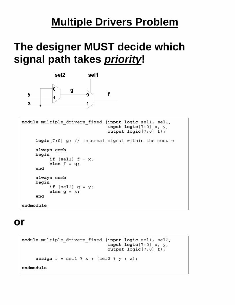
Multiple Drivers Problem
The designer MUST decide which signal path takes priority!
or
module multiple_drivers_fixed (input logic sel1, sel2, input logic[7:0] x, y, output logic[7:0] f);
logic[7:0] g; // internal signal within the module always_comb begin if (sel1) f = x; else f = g; end always_comb begin if (sel2) g = y; else g = x; end
endmodule
module multiple_drivers_fixed (input logic sel1, sel2, input logic[7:0] x, y, output logic[7:0] f);
assign f = sel1 ? x : (sel2 ? y : x); endmodule

Priority Encoders
Equivalent code
module priority_encoder (input logic c1, c2, c3, input logic[7:0] w, x, y, z, output logic[7:0] f);
always_comb begin
if (c1) f = w; else if (c2) f = x; else if (c3) f = y; else f = z; end
endmodule
module priority_encoder (input logic c1, c2, c3, input logic[7:0] w, x, y, z, output logic[7:0] f);
always_comb begin f = z; if (c3) f = y; if (c2) f = x; if (c1) f = w; end
endmodule

Sequential Logic Fundamental sequential element - edge-triggered Data (or D) flip-flop with asynchronous reset (active low) • Combinational logic can be described either using continuous assignments or procedural assignments in “always” or “always_comb” blocks • Sequential logic can be described using “always” or “always_ff” blocks • Latches can be described using “always” or “always_latch” blocks (to be discussed later)
module d_flip_flop (input logic clock, resetn, input logic d, output logic q);
always_ff @(posedge clock or negedge resetn) // “sensitivity list” begin if (!resetn) q <= 1'b0; else q <= d; // this is a “non-blocking” assignment end
endmodule

Registers 8-bit register with synchronous enable All the signals on the left hand side of non-blocking procedural assignments in always_ff blocks will end up as state elements (flip-flops)! IMPORTANT coding conventions: • in “always_comb” blocks use only
“blocking” assignments • in “always_ff” blocks use only
“non-blocking” assignments
module enabled_register (input logic clock, resetn, input logic en, input logic[7:0] d, output logic[7:0] q);
always_ff @(posedge clock or negedge resetn) begin if (resetn == 1'b0) // different way to test for active low q <= 8'b0000_0000; else begin if (en == 1'b1) q <= d; end end
endmodule
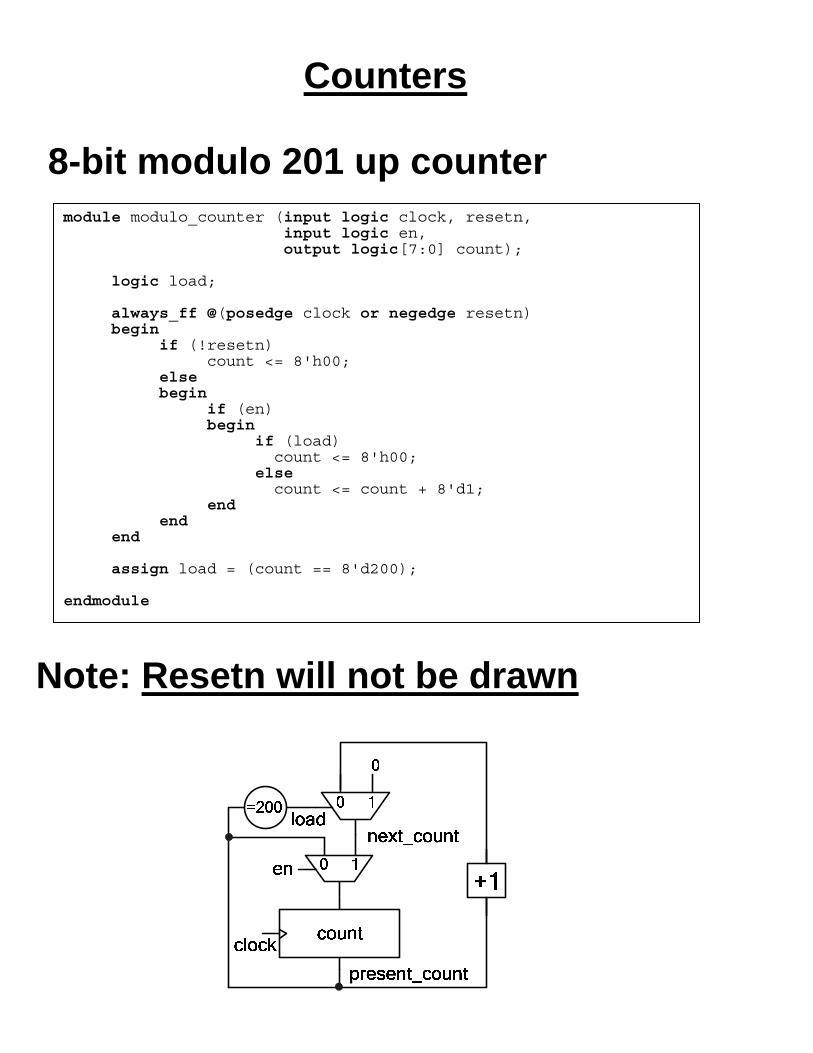
Counters
8-bit modulo 201 up counter
Note: Resetn will not be drawn
module modulo_counter (input logic clock, resetn, input logic en, output logic[7:0] count);
logic load; always_ff @(posedge clock or negedge resetn) begin if (!resetn) count <= 8'h00; else begin if (en) begin if (load) count <= 8'h00; else count <= count + 8'd1; end end end assign load = (count == 8'd200);
endmodule

Counters Equivalent code explaining present_count and next_count
Important note: if a signal is driven in a sequential block (if it appears on the left-hand side of the assignments in an “always_ff” or “always” block with the “sensitivity list” as shown in these examples), then its occurrences on the right-hand side of assignments stand for the present (or current) state that was computed in the previous clock cycle!
module modulo_counter (input logic clock, resetn, input logic en, output logic[7:0] count); logic[7:0] present_count, next_count; assign count = present_count; always_ff @(posedge clock or negedge resetn) begin if (!resetn) present_count <= 8'h00; else if (en) present_count <= next_count; // non-blocking assignment end always_comb begin: next_state_logic // this is a label for naming a block logic load; // declare a signal only for this block load = (present_count == 8'd200); // blocking assignment if (load) next_count = 8'h00; else next_count = present_count + 8'd1; end endmodule

Arbitrary Counting Sequences Reflected gray code sequence
module gray_code_counter (input logic clock, resetn, output logic[3:0] gray_code_count); logic[3:0] binary_count; always_ff @ (posedge clock or negedge resetn) if (resetn == 1'b0) binary_count <= 4'd0; else binary_count <= binary_count + 4'd1; always_comb // next state logic case (binary_count) 4'd1: gray_code_count = 4'd1; // blocking assignment 4'd2: gray_code_count = 4'd3; 4'd3: gray_code_count = 4'd2; 4'd4: gray_code_count = 4'd6; 4'd5: gray_code_count = 4'd7; 4'd6: gray_code_count = 4'd5; 4'd7: gray_code_count = 4'd4; 4'd8: gray_code_count = 4'd12; 4'd9: gray_code_count = 4'd13; 4'd10: gray_code_count = 4'd15; 4'd11: gray_code_count = 4'd14; 4'd12: gray_code_count = 4'd10; 4'd13: gray_code_count = 4'd11; 4'd14: gray_code_count = 4'd9; 4'd15: gray_code_count = 4'd8; default: gray_code_count = 4'd0; endcase endmodule

Arbitrary Counting Sequences Use a state machine approach
gray_code_countclock revisedmapping
logic
gray_code_count
0 1 3 2 6 7 5 4
8 9 11 10 14 15 13 12
This implementation uses only four LEs (in each LE we have one flip-flop used to store the state and one 4-LUT that implements the next state logic).
module gray_code_counter (input logic clock, resetn, output logic[3:0] gray_code_count); always_ff @ (posedge clock or negedge resetn) if (resetn == 1'b0) gray_code_count <= 4'd0; else case (gray_code_count) // next state logic 4'd0: gray_code_count <= 4'd1; // non-blocking assignment 4'd1: gray_code_count <= 4'd3; 4'd3: gray_code_count <= 4'd2; 4'd2: gray_code_count <= 4'd6; 4'd6: gray_code_count <= 4'd7; 4'd7: gray_code_count <= 4'd5; 4'd5: gray_code_count <= 4'd4; 4'd4: gray_code_count <= 4'd12; 4'd12: gray_code_count <= 4'd13; 4'd13: gray_code_count <= 4'd15; 4'd15: gray_code_count <= 4'd14; 4'd14: gray_code_count <= 4'd10; 4'd10: gray_code_count <= 4'd11; 4'd11: gray_code_count <= 4'd9; 4'd9: gray_code_count <= 4'd8; default: gray_code_count <= 4'd0; endcase endmodule

Arbitrary Counting Sequences
What happens if we re-specify the next state logic as a priority encoder?
module gray_code_counter (input logic clock, resetn, output logic[3:0] gray_code_count); always_ff @ (posedge clock or negedge resetn) if (resetn == 1'b0) gray_code_count <= 4'd0; else begin gray_code_count <= 4'd0; // “non-blocking” assignments if (gray_code_count == 4'd0) gray_code_count <= 4'd1; if (gray_code_count == 4'd1) gray_code_count <= 4'd3; if (gray_code_count == 4'd3) gray_code_count <= 4'd2; if (gray_code_count == 4'd2) gray_code_count <= 4'd6; if (gray_code_count == 4'd6) gray_code_count <= 4'd7; if (gray_code_count == 4'd7) gray_code_count <= 4'd5; if (gray_code_count == 4'd5) gray_code_count <= 4'd4; if (gray_code_count == 4'd4) gray_code_count <= 4'd12; if (gray_code_count == 4'd12) gray_code_count <= 4'd13; if (gray_code_count == 4'd13) gray_code_count <= 4'd15; if (gray_code_count == 4'd15) gray_code_count <= 4'd14; if (gray_code_count == 4'd14) gray_code_count <= 4'd10; if (gray_code_count == 4'd10) gray_code_count <= 4'd11; if (gray_code_count == 4'd11) gray_code_count <= 4'd9; if (gray_code_count == 4'd9) gray_code_count <= 4'd8; end endmodule

Control/data path
Control path • finite state machine (FSM)
Data path • registers, arithmetic units (adders,
multipliers), logic units, shift registers, counters, comparators, embedded memories, …
Status signals • comparator results, zero detect, …
Control signals • synchronous enable, load, shift, …
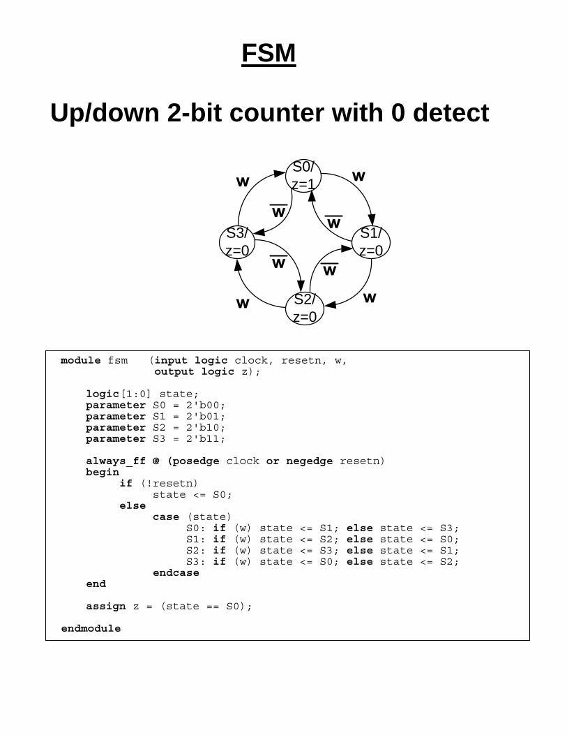
FSM
Up/down 2-bit counter with 0 detect
S0/z=1
S1/z=0
S2/z=0
S3/z=0
module fsm (input logic clock, resetn, w, output logic z); logic[1:0] state; parameter S0 = 2'b00; parameter S1 = 2'b01; parameter S2 = 2'b10; parameter S3 = 2'b11; always_ff @ (posedge clock or negedge resetn) begin if (!resetn) state <= S0; else case (state) S0: if (w) state <= S1; else state <= S3; S1: if (w) state <= S2; else state <= S0; S2: if (w) state <= S3; else state <= S1; S3: if (w) state <= S0; else state <= S2; endcase end assign z = (state == S0); endmodule
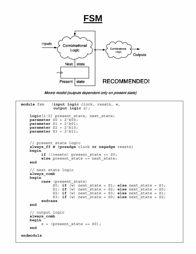
FSM
module fsm (input logic clock, resetn, w, output logic z); logic[1:0] present_state, next_state; parameter S0 = 2'b00; parameter S1 = 2'b01; parameter S2 = 2'b10; parameter S3 = 2'b11; // present state logic always_ff @ (posedge clock or negedge resetn) begin if (!resetn) present_state <= S0; else present_state <= next_state; end // next state logic always_comb begin case (present_state) S0: if (w) next_state = S1; else next_state = S3; S1: if (w) next_state = S2; else next_state = S0; S2: if (w) next_state = S3; else next_state = S1; S3: if (w) next_state = S0; else next_state = S2; endcase end // output logic always_comb begin z = (present_state == S0); end endmodule

Case Study: Pacemaker
“Artificial” pacemaker • medical device that regulates heart beats • listens to heart’s electrical rhythm and if
abnormal activity is sensed then it sends precisely-timed electrical signals
• average heartbeat – approx 70 pulses per minute • if ventricle contraction is not sensed in due time,
a ventricle stimulation is applied by the digital circuitry – treats bradycardia (slow heart rate)
• can be extended to monitoring and stimulating also the right atrium - called “atrioventricular” or “dual-chamber” pacemakers
• can be further extended to adapt to motion and breathing rhythms – called “rate-responsive”
• more complex (yet similar) digital circuitry can be used for implantable cardioverter–defibrillators

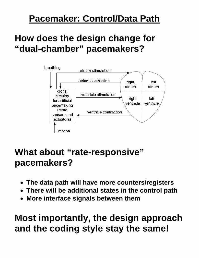
Pacemaker: Control/Data Path
S_REINITIALIZE COUNTER/reload = 1, ventricle stimulation = 0
S_WAIT VENTRICLE CONTRACTION/reload = 0, ventricle stimulation = 0
S_APPLY VENTRICLE STIMULATION/reload = 0, ventricle stimulation = 1
ventricle contraction
zero detect any other case
module pacemaker (input logic clock, resetn // clock period is assumed 10 ms input logic ventricle_contraction, output logic ventricle_stimulation); logic[7:0] counter; // keeps track of how much time has passed since last contraction logic reload; // used to re-initialize the counter (control signal) logic zero_detect; // used to point that no contraction was sensed (status signal) logic[1:0] present_state, next_state; // pacemaker states parameter S_REINITIALIZE_COUNTER = 2'b00; parameter S_WAIT_VENTRICLE_CONTRACTION = 2'b01; parameter S_APPLY_VENTRICLE_STIMULATION = 2'b10; always_ff @ (posedge clock or negedge resetn) if (!resetn) counter <= 8'd0; else if (reload) counter <= 8'd84; // approx 70 pulses per minute else counter <= counter - 8'd1; always_ff @ (posedge clock or negedge resetn) if (!resetn) present_state <= S_REINITIALIZE_COUNTER; else present_state <= next_state; always_comb case (present_state) S_REINITIALIZE_COUNTER: next_state = S_WAIT_VENTRICLE_CONTRACTION; S_WAIT_VENTRICLE_CONTRACTION: begin if (ventricle_contraction) next_state = S_REINITIALIZE_COUNTER; else if (zero_detect) next_state = S_APPLY_VENTRICLE_STIMULATION; else next_state = S_WAIT_VENTRICLE_CONTRACTION; end S_APPLY_VENTRICLE_STIMULATION: next_state = S_REINITIALIZE_COUNTER; default: next_state = S_REINITIALIZE_COUNTER; endcase assign zero_detect = (counter == 8'd0); assign reload = (present_state == S_REINITIALIZE_COUNTER); assign ventricle_stimulation = (present_state == S_APPLY_VENTRICLE_STIMULATION); endmodule

Pacemaker: Control/Data Path
There is no need to declare explicitly all the interface signals between the control path and the data path Shorter equivalent code (“implicit”)
module pacemaker (input logic clock, resetn, input logic ventricle_contraction, output logic ventricle_stimulation); logic[7:0] counter; enum logic[1:0] {S_REINITIALIZE_COUNTER, S_WAIT_VENTRICLE_CONTRACTION, S_APPLY_VENTRICLE_STIMULATION} state; // pacemaker states always_ff @ (posedge clock or negedge resetn) if (!resetn) begin state <= S_REINITIALIZE_COUNTER; counter <= 8'd0; end else begin counter <= counter - 8'd1; case (state) S_REINITIALIZE_COUNTER: begin state <= S_WAIT_VENTRICLE_CONTRACTION; counter <= 8'd84; end S_WAIT_VENTRICLE_CONTRACTION: begin if (ventricle_contraction)
state <= S_REINITIALIZE_COUNTER; else if (counter == 8'd0)
state <= S_APPLY_VENTRICLE_STIMULATION; end S_APPLY_VENTRICLE_STIMULATION: state <= S_REINITIALIZE_COUNTER; default: state <= S_REINITIALIZE_COUNTER; endcase end assign ventricle_stimulation = (state == S_APPLY_VENTRICLE_STIMULATION); endmodule
Pacemaker: Control/Data Path
How does the design change for “dual-chamber” pacemakers?
What about “rate-responsive” pacemakers? • The data path will have more counters/registers • There will be additional states in the control path • More interface signals between them
Most importantly, the design approach and the coding style stay the same!
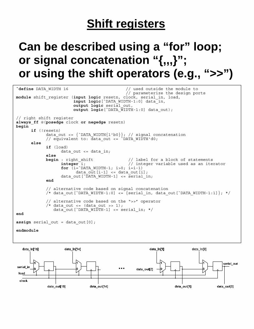
Shift registers Can be described using a “for” loop; or signal concatenation “{,,,}”; or using the shift operators (e.g., “>>”)
`define DATA_WIDTH 16 // used outside the module to // parameterize the design ports module shift_register (input logic resetn, clock, serial_in, load, input logic[`DATA_WIDTH-1:0] data_in, output logic serial_out, output logic[`DATA_WIDTH-1:0] data_out); // right shift register always_ff @(posedge clock or negedge resetn) begin if (!resetn) data_out <= {`DATA_WIDTH{1'b0}}; // signal concatenation // equivalent to: data_out <= `DATA_WIDTH'd0; else if (load) data_out <= data_in; else begin : right_shift // label for a block of statements integer i; // integer variable used as an iterator for (i=`DATA_WIDTH-1; i>0; i=i-1) data_out[i-1] <= data_out[i]; data_out[`DATA_WIDTH-1] <= serial_in; end // alternative code based on signal concatenation /* data_out[`DATA_WIDTH-1:0] <= {serial_in, data_out[`DATA_WIDTH-1:1]}; */ // alternative code based on the “>>” operator /* data_out <= (data_out >> 1); data_out[`DATA_WIDTH-1] <= serial_in; */ end assign serial_out = data_out[0]; endmodule

Bit counting
Combinational implementation – “for” loop
0
1
data_in[0]
1'b11'b0
+10
1
data_in[1]
0
1
data_in[14]
+10
1
data_in[15]
5
data_outLoad
SI<< 0
data_in
data_out
1 0Load
ClockSO
0 1
+1
shift register
0
Combinational implementation Sequential implementation5
16
`define INPUT_WIDTH 16 `define OUTPUT_WIDTH 5 module bit_count (input logic[`INPUT_WIDTH-1:0] data_in, output logic[`OUTPUT_WIDTH-1:0] data_out);
always_comb begin : combinational_solution integer i; data_out = `OUTPUT_WIDTH'd0; for (i=0; i <`INPUT_WIDTH; i+=1) if (data_in[i]) data_out = data_out + `OUTPUT_WIDTH'd1; end
endmodule
// sequential implementation that uses one shift register and one counter module bit_count (input logic resetn, clock, load,
input logic[`INPUT_WIDTH-1:0] data_in, output logic[`OUTPUT_WIDTH-1:0] data_out);
logic[`INPUT_WIDTH-1:0] shift_register; always_ff @(posedge clock, negedge resetn) begin if (!resetn) begin shift_register <= `INPUT_WIDTH'd0; data_out <= `OUTPUT_WIDTH'd0; end else begin if (load) begin shift_register <= data_in; data_out <= `OUTPUT_WIDTH'd0; end else begin shift_register <= (shift_register << 1); // left shift if (shift_register[`INPUT_WIDTH-1]) data_out <= data_out + `OUTPUT_WIDTH'd1; end end end
endmodule
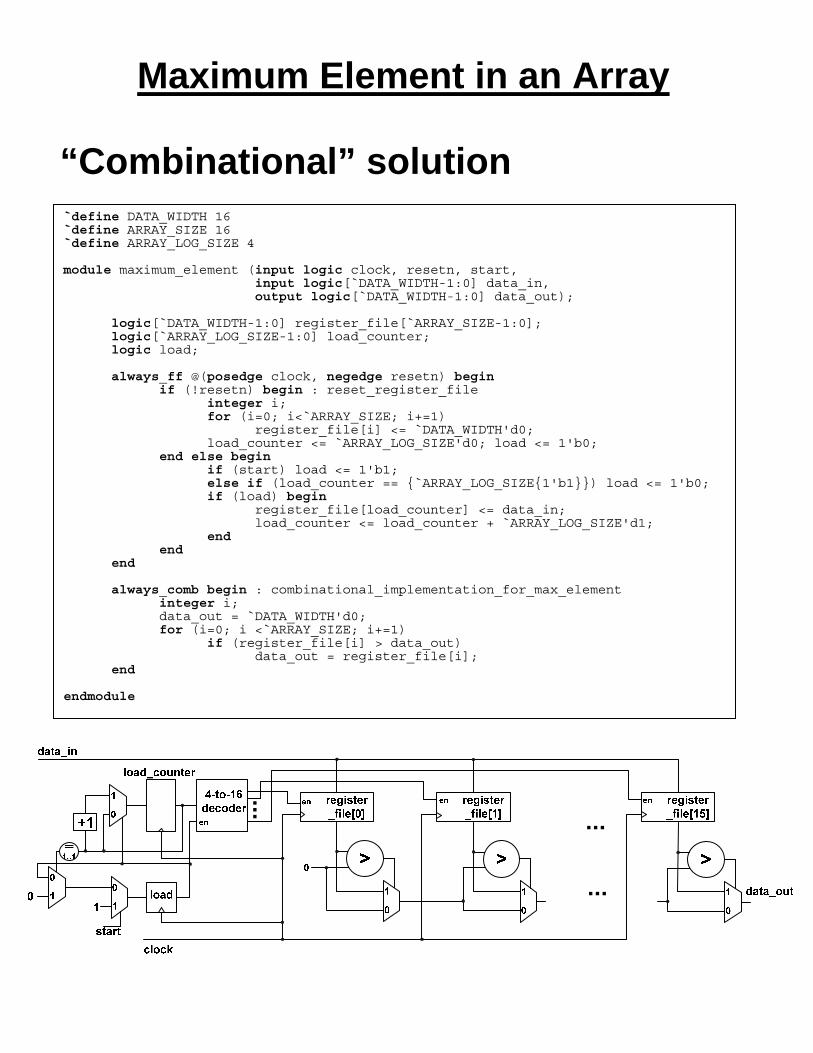
Maximum Element in an Array
“Combinational” solution
`define DATA_WIDTH 16 `define ARRAY_SIZE 16 `define ARRAY_LOG_SIZE 4 module maximum_element (input logic clock, resetn, start, input logic[`DATA_WIDTH-1:0] data_in, output logic[`DATA_WIDTH-1:0] data_out);
logic[`DATA_WIDTH-1:0] register_file[`ARRAY_SIZE-1:0]; logic[`ARRAY_LOG_SIZE-1:0] load_counter; logic load; always_ff @(posedge clock, negedge resetn) begin if (!resetn) begin : reset_register_file integer i; for (i=0; i<`ARRAY_SIZE; i+=1) register_file[i] <= `DATA_WIDTH'd0; load_counter <= `ARRAY_LOG_SIZE'd0; load <= 1'b0; end else begin if (start) load <= 1'b1; else if (load_counter == {`ARRAY_LOG_SIZE{1'b1}}) load <= 1'b0; if (load) begin register_file[load_counter] <= data_in; load_counter <= load_counter + `ARRAY_LOG_SIZE'd1; end end end always_comb begin : combinational_implementation_for_max_element integer i; data_out = `DATA_WIDTH'd0; for (i=0; i <`ARRAY_SIZE; i+=1) if (register_file[i] > data_out)
data_out = register_file[i]; end
endmodule

Maximum Element in an Array
Sequential solution
module maximum_element (input logic clock, resetn, start, input logic[`DATA_WIDTH-1:0] data_in, output logic[`DATA_WIDTH-1:0] data_out);
logic[`DATA_WIDTH-1:0] register; logic[`ARRAY_LOG_SIZE-1:0] load_counter; logic load;
always_ff @(posedge clock, negedge resetn) begin if (!resetn) begin load <= 1'b0; register <= `DATA_WIDTH'd0; load_counter <= `ARRAY_LOG_SIZE'd0; data_out <= register; end else begin if (start) load <= 1'b1; else if (load_counter == {`ARRAY_LOG_SIZE{1'b1}}) load <= 1'b0; if (load) begin register <= data_in; load_counter <= load_counter + `ARRAY_LOG_SIZE'd1; end if (register > data_out) data_out <= register; /* if a signed (2s complement) comparator is to be used */ /* if ($signed(register) > $signed(data_out)) data_out <= register; */ if (start && !load) begin register <= `ARRAY_LOG_SIZE'd0; data_out <= `ARRAY_LOG_SIZE'd0; end end end
endmodule

Latches
Level sensitive storage elements
module latch_example1 (input logic enable, data_in, output logic data_out);
always_latch begin if (enable) data_out = data_in; end
endmodule
module latch_example2 (input logic c1, c2, a, b, output logic f, g);
always_latch begin if (c1) begin f = a; end else if (c2) begin g = b; end end
endmodule
module latch_example3 (input logic c1, c2, input logic a, b, output logic f, g);
always_latch begin if (c1) begin f = a; g = b; end else if (c2) begin f = b; g = a; end end
endmodule
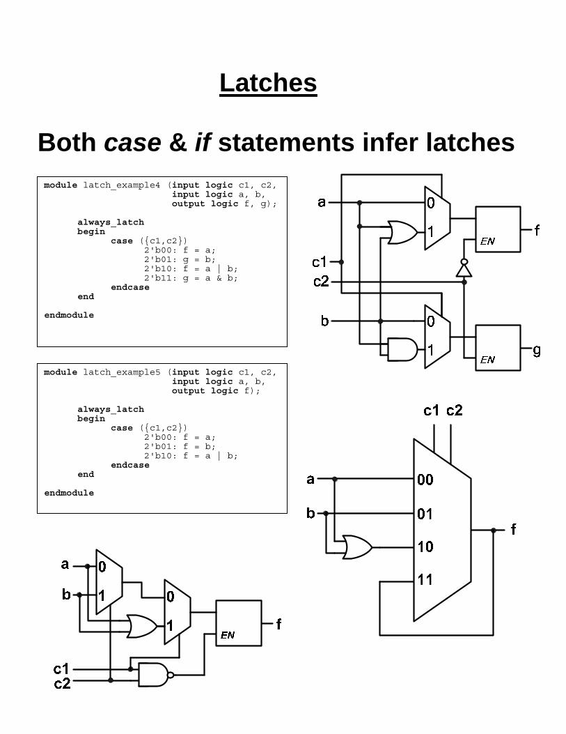
Latches
Both case & if statements infer latches
module latch_example4 (input logic c1, c2, input logic a, b, output logic f, g);
always_latch begin case ({c1,c2}) 2'b00: f = a; 2'b01: g = b; 2'b10: f = a | b; 2'b11: g = a & b; endcase end
endmodule
module latch_example5 (input logic c1, c2, input logic a, b, output logic f);
always_latch begin case ({c1,c2}) 2'b00: f = a; 2'b01: f = b; 2'b10: f = a | b; endcase end
endmodule

Latches
What happens if we use incompletely specified case or if statements with always_comb?
module latch_incorrect (input logic c1, c2, input logic a, b, output logic f);
always_comb begin case ({c1,c2}) 2'b00: f = a; 2'b01: f = b; 2'b10: f = a | b;
endcase end
endmodule
INCORRECT! (the compiler should give an error)
module combinational_correct (input logic c1, c2, input logic a, b, output logic f);
always_comb begin case ({c1,c2}) 2'b00: f = a; 2'b01: f = b; 2'b10: f = a | b; default: f = 1'bx;
endcase end
endmodule
CORRECT! (combinational logic is further optimized by exploiting don’t care conditions)

Blocking vs. Non-blocking Simple circuit for illustrative purposes (in reality some additional inputs/outputs will be required)
clock
module example (input logic clock, output logic[7:0] f); logic[7:0] a, b, c; always_ff @(posedge clock) begin a <= b + c; b <= c + a; c <= a + b; end assign f = c; endmodule

Blocking vs. Non-blocking What happens if assignment to “a” becomes blocking?
clock
module example (input logic clock, output logic[7:0] f); logic[7:0] a, b, c; always_ff @(posedge clock) begin a = b + c; b <= c + a; c <= a + b; end assign f = c; endmodule
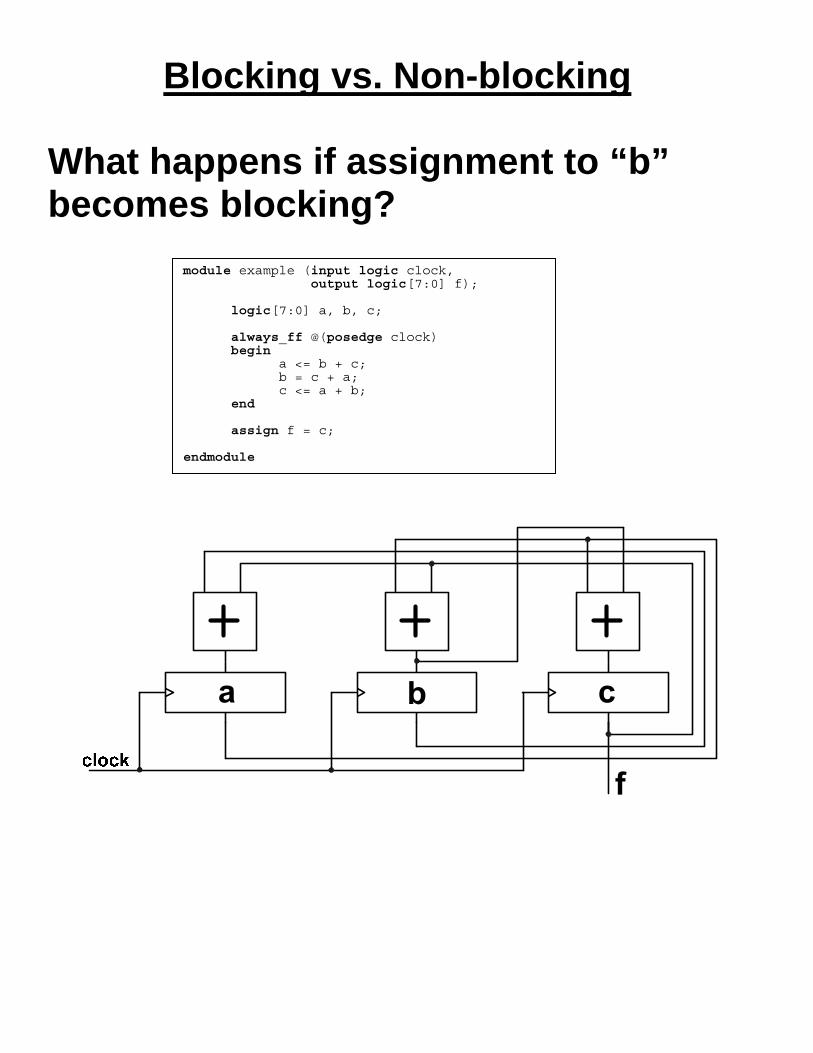
Blocking vs. Non-blocking What happens if assignment to “b” becomes blocking?
module example (input logic clock, output logic[7:0] f); logic[7:0] a, b, c; always_ff @(posedge clock) begin a <= b + c; b = c + a; c <= a + b; end assign f = c; endmodule

Blocking vs. Non-blocking What happens if assignment to “c” becomes blocking?
clock
module example (input logic clock, output logic[7:0] f); logic[7:0] a, b, c; always_ff @(posedge clock) begin a <= b + c; b <= c + a; c = a + b; end assign f = c; endmodule

Blocking vs. Non-blocking What happens if the assignment to “a” is blocking and the output “f” is driven by the “a” signal?
clock
module example (input logic clock, output logic[7:0] f); logic[7:0] a, b, c; always_ff @(posedge clock) begin a = b + c; b <= c + a; c <= a + b; end assign f = a; endmodule

Blocking vs. Non-blocking Can we take the “combinational” “a” signal to the output of the circuit?
module example (input logic clock, output logic[7:0] f); logic[7:0] a, b, c; always_comb begin a = b + c; end always_ff @(posedge clock) begin b <= c + a; c <= a + b; end assign f = a; endmodule