design studies for the electron storage ring euterpe · cip-data koninklijke bibliotheek, den haag...
TRANSCRIPT

Design studies for the electron storage ring EUTERPE
Xi, B.
DOI:10.6100/IR439305
Published: 01/01/1995
Document VersionPublisher’s PDF, also known as Version of Record (includes final page, issue and volume numbers)
Please check the document version of this publication:
• A submitted manuscript is the author's version of the article upon submission and before peer-review. There can be important differencesbetween the submitted version and the official published version of record. People interested in the research are advised to contact theauthor for the final version of the publication, or visit the DOI to the publisher's website.• The final author version and the galley proof are versions of the publication after peer review.• The final published version features the final layout of the paper including the volume, issue and page numbers.
Link to publication
General rightsCopyright and moral rights for the publications made accessible in the public portal are retained by the authors and/or other copyright ownersand it is a condition of accessing publications that users recognise and abide by the legal requirements associated with these rights.
• Users may download and print one copy of any publication from the public portal for the purpose of private study or research. • You may not further distribute the material or use it for any profit-making activity or commercial gain • You may freely distribute the URL identifying the publication in the public portal ?
Take down policyIf you believe that this document breaches copyright please contact us providing details, and we will remove access to the work immediatelyand investigate your claim.
Download date: 26. Aug. 2018


Design Studies for the Electron Storage Ring EUTERPE

CIP-DATA KONINKLIJKE BIBLIOTHEEK, DEN HAAG
Xi, Boling
Design Studies for the Electron Storage Ring EUTERPE I Boling Xi. - Eindhoven : Eindhoven University of Technology Thesis Technische Universiteit Eindhoven. -With ref. ISBN 90-386-0066-6 Subject headings: electron storage rings ; design I electron optics.
Druk: ICG printing, Dordrecht

Design Studies for the Electron Storage Ring EUTERPE
PROEFSCHRIFT
ter verkrijging van de graad van doctor aan de Technische Universiteit Eindhoven,
op gezag van de Rector Magnificus, prof.dr. J.H. van Lint, voor een commissie aangewezen door bet College van
Dekanen in bet openbaar te verdedigen op donderdag 18 mei 1995 om 16.00 uur
door
BOLING XI
geboren te Xi'an, China

Dit proefschrift is goedgekeurd door de promotoren
prof.dr.ir. H.L. Hagedoorn en prof.dr. M.J.A. de Voigt
Copromotor dr. J.LM. Botman

To Yiqian and our parents

Contents
1 Introduction 1.1 Synchrotron Radiation and Electron Storage Rings 1.2 General Concepts of Particle Motion in Storage Rings
1.2.1 Betatron Oscillations ............ . 1.2.2 Synchrotron Oscillations . . . . . . . . . . . 1.2.3 Radiation Damping and Quantum Lifetime
1.3 The Euterpe Project .... 1.4 Scope of the Present Study . . . . . . . . . . . . .
2 Lattice Design 2.1 Introduction . . . . . . . . . . . . . . . . . . . . . . 2.2 Aspects of Ring Optics ............... .
2.2.1 Equilibrium Beam Size and Bunch Length . 2.2.2 Achromats . . . . . . . . 2.2.3 Tune Selection ..... . 2.2.4 Chromaticity Correction . 2.2.5 Natural Emittance ....
2.3 Design of the Lattice for EUTERPE 2.3.1 Basic Lattice Structure and Machine Characteristics 2.3.2 Electron Optical Properties ........... .
2.4 Spectral Characteristics and Emittance Figure of Merit 2.5 Dynamic Aperture . . . . . . . . . . 2.6 Distortion of the Ideal Closed Orbit . .
2.6.1 Main Origins of Distortions ... 2.6.2 Expressions for Distorted Orbits 2.6.3 Estimation of Distortion and Related Tolerances
3 Collective Effects 3.1 Introduction ................ . 3.2 Wall Interaction and Bunch Lengthening. 3.3 RF Voltage and Beam Lifetime . . . . . . 3.4 Intra-Beam Scattering and Emittance Growth . 3.5 Longitudinal Impedance and Beam Lifetime .
v
1 1 4 5 6 7 8
12
15 15 19 19 21 22 23 23 25 25 28 35 36 37 37 38 38
41 41 42 45 46 47

VI
3.6 Beam Current and Bunch Properties 3.7 Gas Scattering and Beam Lifetime 3.8 Conclusion ............. .
Contents
47 48 51
4 Injection 53 4.1 Introduction . . . . . . . . . . . . . 53 4.2 Injectors and Beam Transfer Lines 54 4.3 Injection Procedure . . . . . . . . . 56
4.3.1 Multi-turn Injection with a Fixed Locally Shifted Closed Orbit 56 4.3.2 Continuous Injection with an Adjustable Locally Shifted
Closed Orbit . . . . . . . . . . . . . . . . . . . . . . . . . . . 58 4.4 Effects of Energy Spread, Gas Scattering and Intra-beam Scattering
on the Injection Process . . . . . . . . . . . . . . . . . . . . . . . . .
5 Bypass Line and Bunch Combination 5.1 Introduction ..... 5.2 Bypass Line . . . . . . . 5.3 Bunch Combination ..
5.3.1 Basic Conditions 5.3.2 Extraction and Injection Method
Addendum: Dipole Magnet 1 Introduction . . . . . . . . . . . . . . . . . . 2 Design of Bending Magnet . . . . . . . . . .
2.1 Main Parameters and Characteristics 2.2 Field Errors .. .
3 Measuring Methods ...... . 3.1 Measuring Set-up ... . 3.2 The Measurement Error .
4 Magnetic Performance
6 Concluding Remarks
A Closed Orbit Shift for Injection A.l General Conditions for a Local Shift of the Closed Orbit with a Group
of Kickers ................... . A.2 Local shift of Closed Orbit with Four kickers
A.2.1 Three Kickers ..... · ........ . A.2.2 Two Kickers . . . . . . . . . . . . . . A.2.3 Single Turn Injection with a Single Kicker
A.3 Global Shift of the Closed Orbit with a Single Kicker .
B Feasibility of a Fast Small Kicker System
Reference
60
63 63 64 67 67 69
73 73 73 73 75 77 77 79 80
83
85
85 86 87 88 88 89
91
93

Chapter 1
Introduction
After some notes regarding synchrotron radiation, a few concepts are presented for the description of particle motion. A short overview of the EUTERPE project is given as well as the scope of the thesis.
1.1 Synchrotron Radiation and Electron Storage Rings
Synchrotron radiation is emitted when electrons undergo radial acceleration. The earliest observation occurred probably in the year 1054 when Chinese astronomers recorded a superbright star, which now is known as the crab nebula supernova remnant [1]. The first direct observation of artificial synchrotron radiation was in 1947 with a General Electric 70 MeV Synchrotron [2, 3]. Since then, synchrotron radiation research began parasitically on synchrotrons and storage rings designed and operated for high energy physics studies. For high energy physicists, synchrotron losses have been regarded as a nuisance because they limited the ultimate energy production; however, with the progress of research, many interesting applications for synchrotron radiation in modern science and high technology fields have been found. A dedicated radiation machine, the SOR ring, was built in 1974 [4]. In the Eighties, a rapid worldwide development of synchrotron radiation research and applications occurred and the increasing demand for synchrotron radiated light caused a rapid growth in the number of facilities [5, 6]. To date throughout the world, about 80 storage rings have been put into operation or are being developed as sources of synchrotron radiation [7].
Electron storage rings make available a high intensity, low divergence continuous radiation source spanning a wide wavelength range (from the infra-red into the Xray region) that has excellent directional properties, well-defined polarization and a subnanosecond time structure [5]. Generally, synchrotron radiation is produced by bending magnets in the ring. Nowadays, special insertion devices, such as wigglers
1

2 Chapter 1. Introduction
and undulators, have been developed and used in the new generation machines to produce very high brightness beams of synchrotron radiation.
For users, the most important characteristics of synchrotron radiation are the critical photon energy, the spectral distribution function, the spectral brilliance, the spectral brightness and the time structure.
The critical photon energy hvc is used to characterize the spectral range of a synchrotron radiation source. The spectrum is divided by it into two parts having equal radiated power. The value of hve gives an estimate of the size of the spectrum in the short wavelength region. It is given by [8, 9]:
hve(eV) = 2.22 X 10³ E:~c::.;) = 6.65 x 10²B(T) E 2(GeV), (1.1)
and the corresponding critical photon wavelength is Ae = cfvc, or
A p(m) 18.6 Ae( ) = 5·59 E3(GeV) = B(T) E 2(GeV)' (1.2)
where c is the speed of light, E the energy of the circulating electrons in the ring, p the bending radius of the magnets and B the strength of the bending magnetic field.
Supposing that every bending magnet has the same orbit radius, then the energy loss per electron per revolution is [9]:
E4(GeV) 3 6E(keV) = 88.5 p(m) = 26.5E (GeV) B(T). {1.3)
The total power emitted by the electrons in the bending magnets is:
Ptot(kW) 0.0265E3(GeV) B(T) J(mA), (1.4)
where I is the circulating current in the ring. Synchrotron radiation generated by a vertical magnetic field is emitted tangen
tially to the arc of the trajectory in the horizontal plane and is slightly collimated in the vertical plane. The spectral distribution function is described by [8]:
N(hv) = d4nf(dtd0d/ d.Af.A), (1.5)
where dn equals the number of photons emitted in a time interval dt, with a relative bandwidth d.Af .A, originating from an azimuthal element d() and a current dl ( d() is a small azimuthal interval of the electron orbit from which the radiation is collected).
In practical units, this can be described by:
N(hv) = 2.458 x 10¹⁰ E(GeV) G1(y) (1.6)
where the unit of N(hv) is (photons/sec.fmrad/mA/0.1% band width), and the function Gt(Y) is given by:
(1.7)

1.1. Synchrotron Radiation and Electron Storage Rings 3
with K5t3 (t) being the modified Bessel function of the second kind andy being the dimensionless photon energy y = hvfhv0 •
The spectral distribution function is a universal function of the critical photon energy which in turn is determined by the electron energy and the strength of the bending magnetic fields. Figure 1.1 gives the universal function[10]. For hv = hvc and Gt(1) = 0.651, the spectral distribution function yields:
N(hvc) = 1.60 x 10¹⁰ E(GeV) (photonsfsec.Jmrad/mA/0.1% band width). (1.8)
1011
.g
1 .0 109 '$, -0 .5 108
~
~ 107
1 106
l ~ ws
0.1 1.0 10 100 1000 10000
/Jf..c
Figure 1.1: "Universal" spectral curve.
For experiments in which a monochromatic beam is focused on the sample, the quality of the synchrotron radiation source can be expressed in terms of the spectral brilliance B defined as [8]:
B ::: d7 n/(dt dO ds dl dJ..f >..), (1.9)
where ds is the source area and dQ = d()dfjJ is the solid angle ( ¢ is in the vertical plane). The angular distribution of the synchrotron radiation is described by a Gaussian distribution of the emitted photons and the azimuthal position of the electrons in the beam.
The spectral brightness Bn is also often used to describe the spectral distribution of the radiation source, see reference [8]:
(1.10)

4 1. Introduction
The values of B and Bn for EUTERPE will be given in Chapter 2 (section 4). The time structure of synchrotron light is mainly determined by the radio
frequency {RF) accelerating structure. The duration of each pulse depends on the electron bunch length. The separation between pulses depends on the orbital period of the ring and the RF system. The circumference of the ring must be an integral number of RF wavelengths, its integer being known as the harmonic number. For a specific storage ring, the separation of pulses is shortest when the number of electron bunches is equal to the harmonic number, and the separation of pulses equivalent to the orbital period is longest when the number of electron bunches is one.
It is obvious that the quality of the synchrotron radiation depends mainly on the performance of the storage ring used. Suller [7] defines an emittance figure of merit for storage rings. This will be discussed in Chapter 2.
1.2 General Concepts of Particle Motion in Storage Rings
In this section, some general concepts of particle motion in an electron storage ring will be discussed.
Particles in a storage ring generally show so-called transverse betatron oscillations and longitudinal synchrotron oscillations [11, 12]. These oscillations are deviations with respect to an orbit (also called the trajectory) of a reference particle with nominal energy. The reference particle circulates on a chosen closed orbit (called the central orbit or reference orbit) which is normally situated in the plane of symmetry for the magnetic fields (called the median plane). Figure 1.2 shows a curvilinear coordinate system which is used to describe particle trajectories.
--
-------Median plane
-- p ~B
-,, ' ' ' \
/ /
I I
-/1 ~'i:----------reference
generic trajectory
trajectory
Figure 1.2: Particle trajectories and curvilinear coordinate system.

1.2. General Concepts of Particle Motion in Storage Rings 5
1.2.1 Betatron Oscillations
According to linear theory, the transverse stable motion of a particle can be described by the transverse displacement y(s) (denoting the radial displacement x(s) or the vertical displacement z( s)) and its derivative y' ( s) [11, 12]:
( y(s) ) _ ( Vc110 JJ11 (s) cos(¢(s)- t/lo) )
y'(s) - - J:!k [sin(¢(s)- tflo) + a:(s) cos(¢(s)- t/lo)] ' l'u(s)
(1.11)
where: J(:f; is the amplitude function of the betatron oscillation, tfo(s) is the phase of the betatron oscillation, c110 is a constant, and where the following conditions hold:
dtfo(s) = ds/J'(s), (1.12)
1 a(s) = - 2{3'(s), (1.13)
()_l+a:2(s) 'Y s - J'(s) . (1.14)
Equation (1.11) is the parametric representation of an ellipse centred at the origin (0, 0) (reference closed orbit) in the (y, y') phase plane. It also describes the transverse movements of a family of trajectories with different initial conditions ( ¢0 , e:110 ), representing the beam. The maximum ellipse area divided by 1r is called the beam emittance, see Fig. 1.3.
y' afih
y
Figure 1.3: Phase space ellipse.
It should be noted that the betatron functions P( s) and a:( s) depend on the complete magnet configuration which is called the lattice of the ring. The transverse

6 Chapter 1. Introduction
behaviour of a particle also can be found from [12]
( y(s) ) ( y(so) ) y'(s) = M(s/so) y'(so) , (1.15)
where M(sfso) is a transfer matrix from longitudinal position so to s:
~sin¢s/O
If( cos rPs/0- as sin t/>8 ;o)
(1.16) where tPs/O = ¢(s)- ¢(so) is the phase advance from position so to s.
1.2.2 Synchrotron Oscillations
An electron of energy E, moving along the reference orbit will radiate a certain amount of energy oE per revolution. The radiation loss must be compensated by an energy gain delivered by an RF system. An electron moving along a reference trajectory is called a synchronous electron when its revolution time is equal to (or is an integer multiple of) the period of the RF field. It will gain energy Uo = oE when crossing the acceleration gap in an RF cavity at the synchronous phase l.fJs:
(1.17)
where VRF is the value of the peak voltage. Other electrons with a phase l.fJt will get the following energy while crossing the gap of the RF cavity,
{1.18)
where w0 is the revolution frequency of the synchronous electron and h the harmonic number. Generally, l.fJt =f. l.fJs, but due to different energy gains and synchrotron radiation losses, the non-synchronous electrons with phase l.fJt will show longitudinal synchrotron oscillations around the synchronous electron.
For small amplitude oscillations, using a linear approximation, the synchrotron oscillation frequency Q is given by [11]:
ae VRF(O) ToE
(1.19)
where To is the revolution period of a synchronous electron and a the momentum compaction factor:
dL/L a= dP/P' (1.20)
with P the momentum of the electron and L the length of the orbit of the reference particle.

1.2. General Concepts of Particle Motion in Storage Rings 7
For large amplitude oscillations, according to nonlinear theory (11], the region of stability in the phase space (with two canonically conjugated variables related to energy and phase) is limited by the well-known ''fish" shaped separatrix. The maximum allowable energy deviation 6 Ema:c, called the energy aperture, is given by:
(6Ema:c) 2 = Uo ( 2eVRF-1r). E 1rahE Uo
(1.21)
1.2.3 Radiation Damping and Quantum Lifetime
Synchrotron radiation has a great effect on the motion of the emitting electrons (11]. Each time a quantum is emitted, the energy of the electron makes a small discontinuous jump. Sudden emissions of individual photons excite various oscillations. The discontinuous energy change from the emission of a quantum disturbs the trajectory of the electron. The cumulative effect of many disturbances introduces a kind of "noise" in the oscillations causing their amplitudes to grow. However, for ultra-relativistic electrons the radiation is emitted primarily along the direction of motion. Most of the radiation is emitted within an angle of 1/-r where 1 is the ratio of the electron energy E to the electron rest energy mec2
• On average, the radiation reaction force - and therefore the accompanying momentum change - is exactly opposite to the direction of motion. The average force of the radiation loss produces damping effects on the various modes of oscillation (13]. When an electron passes an RF cavity, it will get an energy gain in the longitudinal direction. After many revolutions the average longitudinal momentum does not change but the transverse momentum decreases a little. Thus, the amplitude of the transverse oscillation will decrease a little too. At the same time, the change in energy loss with energy deviation will add a damping term to the normal stable synchrotron oscillation [14]. As a result, because of the compensation of the energy loss by the RF system, the transverse betatron oscillations and the longitudinal energy oscillation have a natural exponential decay with damping coefficients a,.. (u = :c, z or s) [11]:
6E a,..= J,.. 2ETo' (1.22)
where J,.. is the series of damping partition numbers: J:c = 1-V, Jz = 1, J, 2+V, with V a property of the lattice, typically being a positive number much smaller than 1.
The damping time constants r,.. are just 1/a~.~. For example, for the EUTERPE ring, the energy loss per revolution is 2.3 keV, the electron energy is 400 MeV and the revolution period is 133 ns (see Table 1.2). Then the longitudinal damping time is about 20 ms and the transverse damping time is about 40 ms.
From Eqs. (1.3) and (1.22) it can be seen that, in a storage ring, the damping time constants are inversely proportional to the cube of the energy. Damping has a marked effect on the quantum lifetime (see Eq. (1.24)) of the stored beam. In a sixdimensional phase space, the positions of the electrons can usually be represented with a Gaussian distribution [15]. In order to keep the stored electrons circulating

8 Chapter 1. Introduction
in the ring for a long time, the physical dimensions of the vacuum chamber must be much larger than the standard deviations of the distributions, for only then is there a small probability of the electrons bitting the vacuum wall. Considering the aperture limitation, the loss rate of the stored beam is proportional to the number N of the circulating particles [11]:
dN N (1.23)
dt rq -=--
The number rq is usually referred to as the quantum lifetime of the stored beam:
(1.24)
with
(u=x,z,s), (1.25)
where Umax represents the maximum amplitude of the transverse oscillations and the energy (synchrotron) oscillation (which are design values for the machine), Ux
and u z denote the equilibrium beam sizes in the transverse planes and u3 denotes the energy spread (see the later discussion in Chapter 2). Table 1.1 shows the quantum lifetime as a function of the effective aperture with a unit damping time.
Table 1.1: Quantum lifetime as a function of effective aperture.
3 4 10.00 186.3
1.3 The Euterpe Project
The development of a new generation of synchrotron radiation storage rings is challenging, because special requirements need to be implemented, such as low emittance, high beam currents, a long beam lifetime, a low energy injection, special time structures, high quality light, highly stable operation [16, 17]. Correspondingly, many new aspects of beam dynamics and accelerator technology, such as new types of insertion devices, low emittance, flexible optics, collective effects and beam stability, need to be investigated, which may be significantly different from those in the high energy accelerators used for high energy physics [18, 19].
The Eindhoven University of TEchnology Ring for Protons and Electrons (EUTERPE) is a university project [20]. EUTERPE is a low energy ring, and is being built by the Eindhoven University of Technology (EUT) staff and workshops within the group budget and with EUT stimulation funding [21]. An important objective of EUTERPE is to investigate beam dynamics and to educate students; this may be

1.3. The Euterpe Project 9
Figure 1.4: Perspective view of EUTERPE storage ring.

10 Chapter 1. Introduction
Table 1.2: Main parameters of EUTERPE ring.
Circumference 40 m Electron energy 400 MeV Injection energy 75 MeV Beam current 100 (200) rnA Lifetime 2 hours No. of superperiods 4 No. of dipole magnets 12 No. of quadrupole magnets 32 RF 45 MHz Harmonic number 6 RF voltage 100 kV Min. emittance 5 nm.rad Min. hor. beam size 0.07 rom Pulse length 3.0 em Revolution period of electrons 133 ns Energy spread dElE 3.5 X w-4
Energy loss I turn 2.3 keV Damping times
horizontal longitudinal
Critical wavelength with dipole with 10 T wiggler
SR of undulator (0.6 T, length 1 m, period 2.5 em) fundamental total power power density
45 ms 24 ms
8.3 nm 1.2nm
0.031 keV 3.6W 0.64 W I mrad2
somewhat different from other synchrotron radiation sources or other accelerators. In addition, the ring will have significant capacity available for research which needs synchrotron radiation and it will then function as a dedicated facility. Based on the points mentioned above, the ring has been designed with a highly flexible magnet configuration (called the lattice) structure and four long straight sections, see Fig. 1.4. With this arrangement, different optical options can easily be produced to satisfy different requirements of synchrotron radiation users [22}. The ring has a relatively large circumference for the maximum beam energy. Insertion devices, such as wigglers and undulators, and other equipment, such as kickers and diagnostic tools can easily be incorporated.
The EUTERPE project will be carried out in two phases. In the first phase, the synchrotron radiation in the UV and XUV region will be supplied from regular dipole magnets. Single bunch mode time-dependent studies (the "pulse probe" mode) in photochemistry, biophysics, surface and condensed matter science and molecular and

EUTERPE
400MeV
lOOmA
photon energy (eV)
wave length (nm)
lOT
Figure 1.5: Synchrotron radiation spectrum of EUTERPE ring.
11
atomic physics, can be carried out. In the second phase, a ten Tesla wiggler magnet and various undulators will be tested in the ring. Synchrotron radiation in the soft Xray region and a bright, quasi-monochromatic photon beam will be generated; basic research on free electron lasers and new developments in accelerator technology will be pursued.
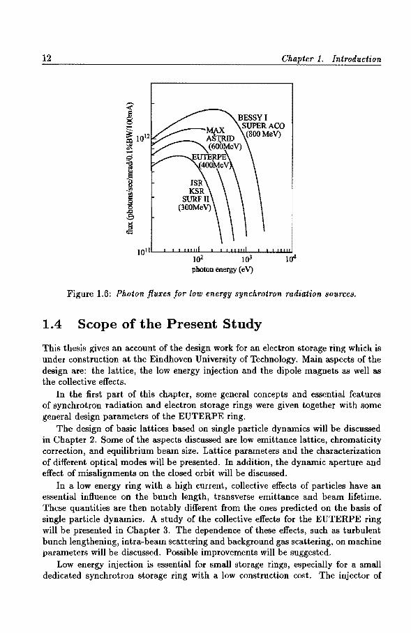
The EUTERPE synchrotron radiation spectrum for a beam current of 100 rnA is shown in Fig. 1.5. The main design parameters of the storage ring are listed in Table 1.2. Figure 1.6 shows the spectral distribution function for various low energy synchrotron radiation sources which are in operation or under construction [6, 23]. It is noted that the spectral intensities (or photon fluxes) from bending magnet in various synchrotron radiation sources are of the same order for photon energies up to 100 e V. In the XUV region, EUTERPE will be competitive with these other machines. Especially, if one takes into account the small emittance of the EUTERPE ring, the spectral brilliance becomes rather high compared to other machines (i.e. the spectral brilliance in units of photons I sec I mrad''f mm2 10.1 %bandwidth is 1013-
1014 for EUTERPE, and 2x10¹² for JSR, 9x10¹² for SURF-II, 2x10¹³ for MAX-I, 9xl013 for SuperACO and 2x10¹³ for BESSY-I [6]).
12 Chapter 1. Introduction
toll'----'-.1..-I....LJ..I~--l---l....J...L..L.I.,I;U--'--...L.J....LI..I.W
103 photon energy ( eV}
Figure 1.6: Photon fluxes for low energy synchrotron radiation sources.
1.4 Scope of the Present Study
This thesis gives an account of the design work for an electron storage ring which is under construction at the Eindhoven University of Technology. Main aspects of the design are: the lattice, the low energy injection and the dipole magnets as well as the collective effects.
In the first part of this chapter, some general concepts and essential features of synchrotron radiation and electron storage rings were given together with some general design parameters of the EUTERPE ring.
The design of basic lattices based on single particle dynamics will be discussed in Chapter 2. Some of the aspects discussed are low emittance lattice, chromaticity correction, and equilibrium beam size. Lattice parameters and the characterization of different optical modes will be presented. In addition, the dynamic aperture and effect of misalignments on the closed orbit will be discussed.
In a low energy ring with a high current, collective effects of particles have an essential influence on the bunch length, transverse emittance and beam lifetime. These quantities are then notably different from the ones predicted on the basis of single particle dynamics. A study of the collective effects for the EUTERPE ring will be presented in Chapter 3. The dependence of these effects, such as turbulent bunch lengthening, intra-beam scattering and background gas scattering, on machine parameters will be discussed. Possible improvements will be suggested.
Low energy injection is essential for small storage rings, especially for a small dedicated synchrotron storage ring with a low construction cost. The injector of

L{. Scope of the Present Study 13
EUTERPE comprises a 75 MeV racetrack microtron [24] which is injected by a 10 MeV (medical) linac. The beam current from the linac is too low to get the required beam current in the ring by single turn injection. How to solve this problem will be discussed in Chapter 4. A procedure for continuous injection with an adjustable locally shifted closed orbit will be presented, as well as general expressions and the choice of kicker parameters for adjustable closed orbit shifts.
A new method for combining bunches will be presented in Chapter 5 together with a description of a by-pass system that can be used for a free electron laser.
The magnetic system of the EUTERPE ring consists of dipoles of unconventional design and construction. The design and measurement of the dipoles will be described in an addendum. The tolerances for the dipoles will be discussed. In addition, there is an analysis of a "banana coil" used to measure integral fields for bending magnets directly.
Concluding remarks will be given in Chapter 6.

Chapter 2
Lattice Design
In this chapter, a description is given of the lattice design, based on single particle dynamics. Design philosophy and design restrictions of EUTERPE are introduced in Section 2.1. General considerations of lattice design for low emittance storage rings are given in Section 2.2. In Section 2.3, the special design of a lattice for the EUTERPE ring and some expressions for its beam characteristics and related parameters are presented, as well as the optical properties of various settings ("modes") for lattice parameters. Spectral characteristics and an emittance figure of merit are given in Section 2.4. Finally, the dynamic aperture and the distortion of the reference closed orbit are described separately in Sections 2.5 and 2.6.
2.1 Introduction
The first idea of a synchrotron ring in the cyclotron building at EUT originated from discussions about a small post-accelerator for the 3 MeV ILEC-cyclotron [25, 26, 27, 28]. With such a machine, which could accelerate protons up to around 20 MeV, the accelerator experiments could be carried out solely for beam dynamical studies, without any particular application in mind. As an example, manipulations in the longitudinal phase space could be undertaken. Design and experiments would be carried out by students in technical physics. This would be a natural follow-up of the accelerator studies on the Philips 30 MeV AVF cyclotron [29, 30, 31] and ILEC, and their beam guiding systems [32]. Orbit dynamics, magnet design, RF-system design, controls, all aspects belonging to larger physics installations would play a major role.
The scene changed slightly when it was realized that the equivalent electron energy in the proton ring was sufficient to allow small scale experiments and applications with synchrotron radiation. The magnetic rigidity of ring elements was raised to 1.35 Tm, corresponding to an energy of 85 MeV for protons, and 400 MeV for electrons. The acronym EUTERPE Eindhoven University of TEchnology Ring for Protons and Electrons was generated by W.A. Bruil. From then on, the empha-
15

16 Chapter 2. Lattice Design
sis was on storing electrons, with a resulting photon spectrum as given in Chapter 1. The expected beam current for synchrotron radiation is 100 rnA or more.
Various factors determined the design of and the philosophy behind EUTERPE. Construction costs obviously had to stay within the accelerator group's limited budget. We had to rely heavily on the university's Central Design and Construction Facilities (CTD), for the construction of the major ring elements, such as magnets, support structures, vacuum chambers, RF cavities, injectors, etc. This has resulted in many innovative mechanical and electrical designs.
Two major parameters determined the design of subsystems for EUTERPE: (a) the maximum electron energy, 400 MeV, and (b) the ring size, circumference 40 m. The maximum energy was set at a compromise between the continuous desire to raise the electron energy, and hence, the critical photon energy, and the financial budget. Small-sized dipole magnets were chosen with a length of 50 em and a magnetic gap of 2.5 em, with laminated material from the transformer industry, allowing the design value of 1.35 Tm for the magnetic rigidity. Straight magnets which provide enhanced radial damping with respect to wedge magnets [33] were chosen. In the Addendum, a detailed description of the dipole design and its performance will be given. The second major EUTERPE parameter is the size of the ring, which was limited by the existing size of the cyclotron experimental hall. In fact, the ring circumference is rather large in view of the maximum electron beam energy, but it provides sufficient room for sophisticated electron optics and for future experiments.
Other influences on the design of the ring were the following: As the electron source for EUTERPE, we obtained a medical linear accelerator
of 10 MeV. Thanks to the collaboration in the TEUFEL project [34], for which a racetrack microtron had been built in our laboratory, it was decided to build simultaneously an almost identical RaceTrack Microtron (RTM) as main injector for EUTERPE. This RTM accelerates electrons from 10 MeV to 75 MeV which determines the injection energy in the ring. Injection elements in EUTERPE had to be designed for this energy, as well as the whole injection line from RTM to the ring. Magnetic ramping during the acceleration in the ring corresponds to the beam energy from 75 to 400 MeV.
As an RF system for accelerating electrons and compensating the energy loss of synchrotron radiation in EUTERPE, it was decided to adopt a 45 MHz RF system whose frequency is near to that of ILEC ( 43.6 MHz ). With the experience on ILEC, a similar design of the RF system could be taken over for EUTERPE [35] almost directly. The chosen frequency implies sixth harmonic operation of the ring, as the revolution frequency is 7.5 MHz; so that in general six bunches circulate in the ring. The RF cavity of approximately 50 em length could be installed in one of the straight sections of the ring, see Fig. 2.1.
The beam lifetime depends on several physical processes, which will be described in Chapter 3. For an adequate lifetime of several hours, a high vacuum, better than 10-9 Torr (133 nPa), is required. Space must be allocated for pumps and gauges. A vacuum chamber for the dipole magnets has been designed [36], with which synchrotron radiation can be partly coupled out, and in this way sufficient pumping

2.1. Introduction
Bd1
Qc8 Qc?
Bc3
Bd3
EU PE 400 MeV
Quadrant d Quadrant a
Quadrant c Quadrant b
Unac 10 10 MeV
Bo1
Figure 2.1: Layout of EUTERPE storage ring.
17
Ba3
Bb1
capacity for synchrotron radiation induced gas desorption can be achieved. In principle, round stainless steel pipes with an outer diameter of 48 mm and wall thickness of 2 mm can be used as the vacuum chamber elsewhere, with flange connections for bellows, monitors, etc., see reference [36].
It was desirable to be able to change certain beam parameters such as the emittance and size at various locations in the ring, in particular in bending magnets, as well as the bunch length. Those factors have a direct effect on the emerging synchrotron radiation. As will be explained in Section 2.2, that can be achieved by adjusting the electron optical parameters. A fourfold symmetric Triple Bend Achromat (TBA) structure, as described in Section 2.2, has been adopted for EUTERPE. With that structure, the desired flexibility is available for altering beam parameters. Three different sets of parameters for the quadrupoles, or "modes" with characteristic beam sizes and bunch lengths, will be given in Section 2.3, together with the reasoning of how to come to those parameter values. The TBA lattice

18
structure leaves four long dispersion-free straight sections, with a free length of two meters each. In order to prevent synchro-betatron coupling, the RF cavity is placed in one of the dispersion-free sections. Another is reserved for the injection elements. The remainder will be used in future for devices like undulators and wigglers, whose operation requires the absence of dispersion.
The EUTERPE project comprises the following sub-systems:
• Magnet system (including support structures): dipoles, quadrupoles, sextupoles, bump and septum magnets for injection, injection line elements, undulators, wigglers, ...
• Alignment and survey system [37]
• RF system
• Vacuum system
• Injector chain: Linac, RTM.
• Power supplies
• Beam monitoring and control system [38]
• Shielding and radiation protection
• Synchrotron radiation beam lines and experimental set-ups
Construction of most of these sub-systems is being carried out in collaboration with the CTD and other faculties at EUT. The completion of the EUTERPE project requires modest additional funds, mainly for power supplies, vacuum, monitoring and control systems.
Many of the items mentioned above are not the subject of this thesis. The remaining part of this chapter will be concentrated on lattice design. The basic linear lattice often comprises identical cells. Each cell consists of bending dipoles and focusing quadrupoles. The number of cells is the so-called number of superperiods of the lattice. Lattice design needs to be in accordance with specific requirements for the machine, taking into account the allocated budget, and obeying the state of the art in technology. Lattice design is a basis of the machine design as a whole. On one side, it determines the performance of the machine and provides the requirements for every sub-system. On the other side, the performance of sub-systems, such as the vacuum system, the injection system, the magnet system, the RF system and the control system, put limitations on the lattice design. The linear lattice is the first structure to be defined. In practice, trade-offs in lattice design have to be made.
Before a detailed explanation of the EUTERPE lattice design is given, some basic beam characteristics of an equilibrium situation in a ring will be introduced along with some general considerations for lattice design.

2.2. Aspects of Ring Optics 19
2.2 Aspects of Ring Optics
Several aspects of electron optics in a storage ring are relevant during the design process of the lattice structure. They include the equilibrium beam size and bunch length, the concept of achromatic bending sections, the selection of tune values, the correction of chromaticity and the minimization of natural emittance in the ring.
2.2.1 Equilibrium Beam Size and Bunch Length
In an electron storage ring, the beam reaches a state of equilibrium when the excitation of both transverse and longitudinal oscillations by quantum emission is balanced by the damping originating from the action of the RF system. Because of the statistical nature of the quantum emission, the equilibrium is characterized by a Gaussian distribution. Details of single particle dynamics were given by M. Sands (11]. Here are some major factors.
1. Relative energy spread.
In the equilibrium state the relative energy spread u dE is given by:
(2.1)
where J11 is the so-called damping partition number for synchrotron oscillations, 1 the ratio of the electron energy and the electron rest energy, Cq = 3.84x 10⁻¹³ (m) and for an arbitrary function f(s):
{f(s)) = If f(s) ds,
with L the orbit length (circumference ofthe ring).
2. Bunch half-length.
The bunch half-length Ur, expressed in units of time, is given by:
2 _ a ToE (u£) 2
Ur - • . e VRF(O) E
This corresponds to a spatial extent u,, which is given by:
(2.2)
(2.3)
(2.4)
where v is the speed of circulating electrons (in electron storage rings v ~ c, the speed of light). It is quite common for the RF voltage of a storage ring cavity to have a sinusoidal variation with time. From Eqs. (1.17) and (1.18), it follows that:
( )
2
1- ~ eVRF
(2.5)

20 Chapter 2. Lattice Design
Generally, eVRF > Uo. Then, equations (2.3-2.4) can be written as
(2.6)
and
(2.7)
3. Beam size.
The spread U:cp in the horizontal size of a stored electron beam due to quantum excitation induced betatron oscillations is characterized by the natural emittance:
where f3:c(s) is the horizontal beta-function at the longitudinal positions, J:c and J. the damping partition numbers in the horizontal and longitudinal direction, respectively, and H(s) a function specified by the properties of the guide field:
1 1 H(s) = {3(s) {D2(s) + [{3(s) D'(s) - 2 f3'(s) D(s)]2
}, (2.9)
with D(s) the dispersion (or off-energy) function (see section 2.2.2.) and D'(s) = dD(s)jds.
The root-mean-square radial spread due to energy spread is:
(2.10)
Generally, the periods of the energy oscillations and the betatron oscillations differ widely; therefore, it can be considered that they will be statistically independent although induced by the same stochastic events. Hence, the total radial spread is:
(2.11)
Considering the quantum effects on the vertical betatron motion:
(2.12)
and (2.13)
since D(s) = 0 at any position in the vertical direction, assuming the bending is only in the horizontal plane.

2.2. Aspects of Ring Optics 21
Comparing Eq. (2.8) and Eq. (2.12), the vertical oscillations induced by quantum emission are smaller in size than radial oscillations by roughly a factor 1/"12 • Hence, the vertical oscillations given by Eq. (2.12) are always negligible in comparison with the vertical oscillations produced by another, much larger, effect - a coupling of oscillation energy from the horizontal betatron oscillations into the vertical ones. Coupling always exists because of construction imperfections, such as rotational misalignments of the quadrupoles and the dipoles. Let x: be the "coefficient of coupling" defined by: x: = £x0 / £z 0 , then the natural emittances C:x0 and £z0 are:
C:x
C:xo = 1 + x;'
x; C:x
Czo = 1 + x;'
(2.14)
(2.15)
where C:x is to be taken from Eq. (2.8) and x: is a number between 0 and 1. Normally, for a good machine, x: can be kept smaller than 0.1. The beam height can be estimated by:
(2.16)
4. Equilibrium beam in an isomagnetic guide field.
The guide field of a storage ring is isomagnetic when it is designed to have a curvature of 1/ p(s) = 1/ Po in all bending magnets and 1/ p(s) = 0 elsewhere. For an isomagnetic guide field, the expressions for the relative energy spread, the natural beam emittance and the beam size can be simplified to:
Cq "/2
Js Po' Cq {H}mag "/2
Jx Po
Ux(s) €x 0 f3(s) + [D(s) ~]2
Js {H}mag f3(s) + D2(s) (O"Ef)' Jx 1 + X:
where (H)mag is the average of H(s) taken only in the bending magnets, i.e.
(H}mag = ~ 1 H(s) ds. 7r Po mag
2.2.2 Achromats
(2.17)
(2.18)
(2.19)
(2.20)
Electrons with a relative energy deviation !.lE f E will be bent more or less than the reference electron in bending magnets. In a storage ring, they move around the

22 Chapter 2. Lattice Design
closed orbits that deviate from the reference orbit by an amount:
AE x(s) = D(s) Ff· (2.21)
Obviously, in general, these closed orbits will not coincide with the axes of the quadrupoles.
It is often necessary to put special devices, such as an RF cavity or an injection system, into straight sections of a ring. Especially for the new generation of synchrotron radiation sources, undulators and wigglers are used as the insertion devices. For avoiding excitation of radial oscillations, it is often necessary to have the dispersion function D(s) = 0 in many of the straight sections. In such dispersion-free sections which may contain quadrupoles, the closed orbit for different energies coincides with the quadrupole axis. A bending section which bends particles without dispersion is called an achromatic section.
2.2.3 Tune Selection
The number of betatron oscillations in one revolution is called the betatron tune vy
(y refers to either a: or z), which is given by (see Eq. (1.12)):
¢ 1 f ds lly = 211" = 21r /1y{s) · (2.22)
The selection of the tune values is important for the beam emittance and the stability of betatron oscillations. The resonance condition for betatron oscillations is:
lvrc + mvz = p, (2.23)
where l, m and p are integers, I l I + I m I is the order of the resonance and p the harmonic number of the Fourier component in the guiding field that drives the resonance. This equation will define a set of lines for each order of resonance and for each value of the integer p in a diagram which is the so-called working diagram (with lla: and liz as coordinates in the operating region of the ring) [39].
The resonant growth of the betatron oscillations may be excited by unavoidable misalignments or imperfections of magnetic elements in the lattice. In order to avoid this, the working values of the tunes have to be kept away from the resonance lines, especially from the systematic resonance lines of the lower orders (up to 3 or 4) given by:
lv31 + mvz = p n3 X integer, (2.24)
where n3 is the number of superperiods of the lattice. Random fluctuations in multipole elements need special attention because they
generally influence the width of the resonances [39]. Non-linear field errors will produce different tunes for the different particles depending on the betatron amplitude or momentum defect. Machine imperfections need to be known in order to get an insight into the machine's acceptance.

2.2. Aspects of Ring Optics 23
2.2.4 Chromaticity Correction
In a storage ring, particles with a different momentum will experience a different focusing strength in the quadrupoles and, as a consequence, will have a different betatron oscillation frequency. This can be represented by the chromaticity ey which is defined as:
(2.25)
In strong focusing lattices, the main contribution to the chromaticity comes from the quadrupoles, and is given by [11, 40, 41]:
(2.26)
with kly(s) the normalized quadrupole gradient (with a dimension of length-2)
defined as:
k1 ( ) _ e 8Bz(s)
y 8 - p {)y . (2.27)
The chromaticity produced by a linear lattice is called the "natural" chromaticity. For the operation of most storage rings, there are two reasons for adjusting the chromaticity to zero or making it slightly positive; firstly, to avoid off-momentum particles crossing resonances and being lost if the "natural" chromaticity is strong; secondly, to avoid the "head-tail effect" in high current beam bunches [42]. To compensate for the "natural" chromaticity, sextupoles can be introduced. The normalized strength (with a dimension of length - 3) of the sextupole is:
k2 () _ e 82 B11 (s)
yS-p {)y2.
The contribution to the chromaticity from the sextupoles is:
ey •• ..,. = 411r f (J11 (s) k2 11 (s) D(s) ds.
2.2.5 Natural Emittance
(2.28)
(2.29)
Apart from the inherent geometrical distribution of synchrotron radiation, it can be seen from Chapter 1 that the brilliance of synchrotron radiation is inversely proportional to the emittance of the electron beam. An aim of our lattice design is to achieve a small value for €x· From equations (2.8, 2.18), it can be seen that since:
(H}mag 12
f:x <X J ' :cPo (2.30)
E::c is dominated by the lattice properties at a certain electron energy E. In order to reduce the emittance, a guide field with a large Po and (or) a large J:c should be used. Unfortunately, taking a large radius Po will increase the length of the guide

24 Chapter 2. Lattice Design
field and increase the cost of the machine. For isomagnetic structures with a large number of cells, the value of Jx is known to tend towards unity [7]. Then, the only way to minimize the emittance is to minimize the function {H}mag·
A variety of lattice types is available for designing low emittance rings. The main types are FODO, CG, DBA and TBA [43, 7]. Fig. 2.2 shows the basic lattice structure and the dispersion behaviour.
FODO
CG/DBA
TBA
Figure 2.2: Basic lattice structure.
A FODO lattice consists of a sequence of alternating focusing and defocusing quadrupoles. The space between the quadrupoles may or may not be occupied by homogeneous bending magnets. It is the most commonly used lattice for high energy physics storage rings. However, it is an uneconomic option in small rings because special lattice sections have to be introduced to achieve dispersion-free sections.
A basic cell of a Chasman-Green (CG) lattice consists of two symmetric bending magnets with a focusing quadrupole at the centre point between them. The strength of the quadrupole has to be adjusted so that the dispersion generated by the first bending magnet is cancelled out by the second. Outside this cell, straight sections contain other quadrupoles which will not affect the dispersion, but will control the lattice functions in the straight sections. The CG lattice may provide long dispersionfree sections, but the lattice functions are rather fixed because of the fixed phase advance in the achromat cell. An improvement is to replace the single dispersion controlling quadrupole by several quadrupoles. That is called the Double Bend Achromat (DBA) lattice with greatly enhanced flexibility for adjusting the lattice functions while maintaining zero dispersion in the long straights.
Putting a third bending magnet in the finite dispersion region in the middle of the DBA lattice defines a Triple Bend Achromat (TBA) structure. With the extra bending magnet, more quadrupoles can be placed in the achromat around the central bend and this gives more parameters for adjusting the phase advance and

2.3. Design of the Lattice for EUTERPE 25
the lattice functions, including the dispersion function. Hence, the TBA structure is very suitable for producing low emittances. Furthermore, this structure offers an opportunity to realize several optical modes because of the high flexibility of the lattice.
By creating the appropriate functions D:c,!3:c and their derivatives in the bending magnets, the value of (H} can be minimized in various types of lattices. The minimum horizontal natural emittance is given by [7, 43]:
(nm.rad), (2.31)
where N is the number of bending magnets in the ring, E the beam energy in Ge V and ki a factor depending on the shape of the lattice structure, i.e. :
kFODO 1
= 12v'15'
kcG/DBA 1
(2.32) 4v'15'
kTBA 7
36v'15.
2.3 Design of the Lattice for EUTERPE
2.3.1 Basic Lattice Structure and Machine Characteristics
Considering its good flexibility, the TBA structure has been chosen as a basis of the EUTERPE lattice. The basic structure consists of three 30° bending magnets with two quadrupole doublets put in symmetric positions within the dispersive region in order to adjust the H function, also with two extra doublets symmetrically placed outside the TBA cell in order to adjust the lattice functions in the straight sections. The basic lattice structure is shown in Fig. 2.3. Four sextupoles are put in position near the two quadrupole doublets inside the TBA cell for chromaticity correction.
I 0
I 4 6 8
S (m)
I 10
Figure 2.3: The basic lattice structure of the EUTERPE ring. B1, B2, Ba are bending magnets; Q1, Q2, · · ·, Qs are quadrupoles; S1, S2, Sa, S4 are sextupoles. In symmetric modes, Qs = Q4, Q6 Qa, Q7 = Q2, Qs = Q1, Sa= S2 and S4 = S1.

26 Chapter 2. Lattice Design
Taking half a meter as the magnetic length of each bending magnet, the bending radius will be about one meter. Substituting J.:::::: 2 and J~:::::: 1 in Eqs. {1.21-1.25, 2.7, 2.14-2.19), the basic parameter relations for the EUTERPE ring (where the lattice functions {3, D and Hare expressed in m, and the energy E in MeV) can be obtained:
1. Nat ural energy spread
Ue "'-~ 4 4 10-7 E"" . X 1'·
2. Natural emittance
€~:::::: 3.8 X 10⁻¹³ (H)mag 12 (m.rad).
3. Beam width
u~(s):::::: 4.4 X 10⁻⁷ J l :,. fJ~(s)(H)mag + D 2(s)1.
4. Beam height
2~~: Uz(s):::::: 4.4 X 10⁻⁷
-1-f3z(s) (H)mag 1'· +~~:
Supposing ,. = 0.1 1 , then
Uz ( S) :::::: 1.3 X 10⁻⁷ .)2 f3z (s) {H}mag 1'·
5. Natural bunch half length
6{1i;/e r:: U! R: 7.0 X 10- -,-yet/. hVRF
6. Damping time constants
2.97 x w- 3
Tu = (second),
7. Quantum lifetime
(2.33)
(2.34)
(2.35)
(2.36)
(2.37)
(2.38)
(2.39)
8.25 X 10⁻⁷ exp [0.5(uma~/uu)2 ] Tq = 3 ( I )2 lu E Uma~ Uu
(hours) (u = x, z, s), (2.40)
where: Xma~ and Zma~ are the maximum amplitudes of the transverse oscillations which are limited by the transverse machine aperture; Sma~ is the maximum amplitude of the energy oscillation which is restricted by the energy aperture of the machine; u ~ and u z are the equilibrium beam sizes in the transverse planes; u8 is the energy spread.
1 This seems to be a. realistic value [44].

2.3. Design of the Lattice for EUTERPE 27
Table 2.1: The lattice parameters in EUTERPE and equilibrium beam parameters at 400 MeV.
Modes a HBSB SBL HLF Dipole (T) B 1.3539 1.3539 1.3539
kl 4.396 1.732 1.184 Quadrupole (m-2) 6 k2 -4.500 -0.432 -0.428
ks 7.351 -3.777 -1.980 k4 -1.794 6.203 4.766
Sextupole (m-") c Sl 416.5 -128.7 -128.7 S2 -561.5 57.6 120.7
Tune llx 5.13 3.37 2.57 liz 2.47 2.41 1.63
Momentum oompaction fadm ~ 1.09x1o-:e 1.88x10 ·l'i 4.06x10 ·Jl
23.83 8.24 10.33 11.11 9.11 8.06
Betatron and Dispersion Dmax 0.49 1.04 0.85 functions (m) (f3x} 7.69 3.76 5.67
(f3z} 6.64 4.58 4.81 (D) 0.14 -0.21 0.27
Nat ural chromaticity (:~: -15.9 -3.7 -2.9 ez -11.0 -8.4 -5.7
Natural emittance (nm.rad) Sx 5.78 155 184 10% coupling (nm.rad) S:~:o 5.25 141 168
Energy spread aefE 3.47xl0-4 3.47x10⁻⁴ 3.47~
Beam length (em) (}'I 1.95 0.08 3. axbaxa 0.06 0.56 0.89 {}'zb aza 0.08 0.35 0.36
Beam size ( mm) d ax2 0.08 0.45 0.38 az2 0.06 0.11 0.20 axo 0.35 1.14 1.31 azo 0.01 0.19 0.25
a See section 2.3.2. b k1, k2 etc. are the scaled focusing strengths belonging to C)l, Q2 etc. (see Fig. 2.3), as given by Eq. (2.27). e Sl, 82 etc. are the scaled sextupole strengths belonging to sl' s2 etc. (see Fig. 2.3), as given by Eq. (2.28). d At the different longitudinal positions (see Fig. 2.3.) represented by the subscripts:
0 - middle of long straight section; 1 - dipole Bl; 2 - dipole B2; 3 dipole B3.

28 Chapter 2. Lattice Design
Table 2.2: Lengths of basic lattice elements.
Elements Number Length (m) Dipole 12 0.516 Quadrupole 32 0.274
16 0.050 4 2.000 16 0.165 24 0.600 16 0.450
Since the transverse machine aperture of EUTERPE is fixed by the choice of dipole and quadrupole design, a vacuum chamber with a vertical aperture of 23 mm within the bending magnets and with a circular aperture of 44 mm in other places was selected. From the earlier formula, it can be seen that the quantum lifetime at 400 MeV will be more than 5000 hours provided that the machine aperture Umax is larger than 7uu. To achieve that, the beam height O'z needs to be restricted to 1.5 mm in the bending magnets and to 3 mm in other places, and the beam width u x
needs to be restricted to 3 mm everywhere in the ring. Correspondingly, the peak voltage of the RF cavity VRF (see Eq. (1.21)) needs to be:
Vi > [(7u£)2 1rha:E ] U0 RF_ E Uo +1r 2e· (2.41)
Substitution of the values for ud E, h, a:, E and Uo, as given in Tables 2.1 and 1.2, in Eq.(2.41) will yield a minimum peak RF voltage of about 6 kV. In practice, however, a higher peak RF voltage than 6 k V will be needed in order to get sufficient Touschek and gas scattering lifetimes, which will be discussed further in the next chapter.
Table 2.1 shows the basic lattice parameters for the EUTERPE ring and the main beam parameters at an energy of 400 MeV. They were obtained for three different electron optical modes, as will be explained in Section 2.3.2. Table 2.2 shows the lengths of basic elements of the lattice structure.
2.3.2 Electron Optical Properties
The focusing strengths of groups of quadrupoles can be selected in order to obtain different electron optical modes in the storage ring. With the computer codes DIM AD [45] and MAD [46], detailed numerical investigations have been done for optimized parameter sets of quadrupole families in three specified modes, namely the HBSB, HLF and SBL mode.

2.9. Design of the Lattice for EUTERPE 29
1. HBSB mode
The High Brilliance Small Beam or HBSB mode is the one in which the beam size is very small in bending magnets. With this mode, the highest brilliance of synchrotron radiation can be achieved. From the discussion in Section 2.2.5 and from the basic parameter relationships for the EUTERPE ring in Section 2.3.1, it can be seen that it is most important to minimize the dispersion function D( s) in bending
o, 02 Q3 Q4 04 03 Q2 o,
25
v =5.13 ' ....._20 v =2.47
E z '-'
c:: 15 f3,
u 0 ;-, ,r/\ "'- 10 \f3, 5 \ I
QQ. 5 \ \ \ ' ' 0
0 2 4 6 8 10 S (m)
Figure 2.4: Lattice functions for EUTERPE in the HBSB mode.
Ill N 'iii
.4
.3
E .2 0 Ill Ill
.1
v =5.13 X
v =2.47 z
.0+------,,------.------.------.~----~ 0 2 4 6 8 10
S (m)
Figure 2.5: The natural equilibrium beam size in the HBSB mode.

30 Chapter 2. Lattice Design
magnets for minimizing its contribution to the beam size due to energy spread, and to minimize the function f3x(s) and (H(s)), which again implies minimizing D(s) in the first place. In the achromatic section, the dispersion coming up in the outer dipoles (see TBA lattice structure in Fig. 2.2), is reduced to nearly zero in the central dipole with the inner quadrupoles. Generally, this needs strong focusing and the corresponding horizontal tune to have a high value. It can be checked that the phase advance between the centers of the outer dipoles is about 27r, which indicates an overall tune of more than 4. Hence there is strong focusing horizontally; the focusing in the vertical direction must be kept smaller. The final setting of the quadrupoles is done for getting suitable values of the beta-functions in different places.
1.0 +----1----'----"'----'------'----1-
0.5
'-U c ...::, 0.0
b
-0.5
o start and end of achromatic section
-1.0 -t---.,..---.---r-----,r----r---+ -0.50 -0.25 0.00 0.25 0.50 0.75 1.00
Dispersion D (m)
1.0 -+---__.. ___ __.___ __ ___.. ___ _,__ __ -+
........ 0.5 r ...., .. f'i\D "C
I :l ... c ...::,
I I ,... ,.d ..
b ... .f'. I .
0.0 I
I I 'a· 0 -0.5 I_ I
o, 02 o, o. o. o, OzOt
-1.0 0 2 4 6 8 10
S {m)
Figure 2.6: The double achromatism in the HBSB mode.
A suitable group of values for the quadrupole strengths has been selected for this mode, see Table 2.1. In this case, the natural emittance e:x is about 5 nm.rad and the beam size in the bending magnets is less than 0.1 mm, with the tunes Vx = 5.13 and Vz = 2.47. Figure 2.4 shows the lattice functions in this HBSB mode. Figure

2.9. Design of the Lattice for EUTERPE 31
2.5 shows the corresponding beam sizes. Double achromatism is demonstrated in Fig. 2.6.
The HBSB mode requires the use of strong focusing in the quadrupoles and the creation of a small value for the dispersion function. Unfortunately, this will give rise to a large natural chromaticity and strong sextupoles are required for compensating the chromaticity. However, the strong non-linear sextupoles will cause side-effects which decrease the stable phase space and make the betatron movements sensitive to field errors, see the discussions in Sections 2.6 and 2.7.
Figure 2.7: Lattice functions for EUTERPE in the HLF mode.
01 Oz Q~ 04 04 Q3 Q2 Q,
2.0
v.=2.57
1.5 II =1.63 '
fl . <1.1 1.0 N
'(ij
E 0 <1.1
0.5 £D cr ' -...... ---- /
0.0 0 2 4 6 8 10
S (m)
Figure 2.8: The natural equilibrium beam size in the HLF mode.

32 Chapter 2. Lattice Design
2. HLF mode
If a small emittance is not very important, for instance in the case of applications in which there is more interest in high flux, a low value of the tunes can be selected to reduce the side-effects. The HLF mode is an optical mode in which a High synchrotron Light Flux can be produced in bending magnets. Generally, suitable transverse tunes for this mode are in the low value range and the focusing strengths are much smaller than those in the HBSB mode. The beta-function changes along the whole lattice are not as radical as those of the HBSB mode. The characteristics of the HLF mode make the beam less sensitive to nonlinear effects, misalignments and field errors of the guide field in the ring, see a later discussion. The achromatic section now closely resembles that of an achromatic system with two bending magnets and a central quadrupole (as in a basic cell of the CG lattice). The central bending magnet here functions similarly as a central quadrupole. Then the phase advance between the midpoints of the outer dipoles will be about 1r.
1.0
0.5
u ~ 0.0
b
-0.5
o stort and end of achromatic section
-1.0 -0.50 -0.25 0.00 0.25 0.50 0.75 1.00
Dispersion D (m)
1.0
t.r" ·· .. ·. D
1 u 0.5 I 1
0 I ..=:. 1
b I 1 0.0
1 \_ I
Cl -0.5
o, 02 OJ o. 02 o,
-1.0 0 2 4 6 8 10
S (m)
Figure 2.9: The double achromatism in the HLF mode.

2.3. Design of the Lattice for EUTERPE 33
A suitable group of parameters and the related beam characteristics are listed in Table 2.1. The lattice functions in this HLF mode are shown in Fig. 2.7. The corresponding beam size and double achromatism are shown separately in Fig. 2.8 and Fig. 2.9. The property of a rather error-insensitive operation of the ring makes the HLF mode more useful for the first phase of the commissioning of the machine.
3. SBL mode
The Short Bunch Length or SBL mode is an optical mode in which a short bunch length of the order of several mm corresponding to several ps can be produced.
10
/"\ v.=3.37 .....
8 I \ I \
'E I \ v =2.41 I \ % I \ '-" \ 6
I fi I I \ 0 z I \ I -:;;-4
I I \ 0 \... I '--" \ s 2
<Q.
0 b
-2 0 2 4 6 8 10
S (m)
Figure 2.10: Lattice functions for EUTERPE in the SBL mode.
From Eqs. (2.7) and (2.38), it can be seen that the bunch half-length depends on the peak RF voltage, harmonic number and momentum compaction factor. Generally, a small value of lTI (or lTT) is given by a large value of VRF or h. Alternatively, the momentum compaction factor can be restricted to a very small value by an oscillatory behaviour of the dispersion function with small negative values in the long straight sections. A suitable set of lattice parameters and main beam characteristics for the SBL mode are given in Table 2.1. Figure 2.10 shows the lattice functions. One can see that, in contrast to the HBSB mode and the HLF mode, there is no double achromatic behaviour in the SBL mode.
In practice, collective effects can cause so-called bunch lengthening which makes it very difficult to obtain a short bunch length, especially in the case of a large beam current. This will be discussed in Chapter 3.
4. Other modes
By a proper setting of the strengths of the quadrupoles, other optical modes with different beta-functions can be obtained, such as the one with a high f3z value

34 Chapter 2. Lattice Design
and a low f3x value in the long straight sections [21]. Furthermore, optical modes with asymmetric superperiods can be realized with the chosen lattice structure, see Figs. 2.11 and 2.12. There, the quadrupoles Q1, Q2, Qs and Q4 have been chosen as alternately focusing and defocusing (AFD).
01 02 03 Q4 01 02 o3 a. 14
12 (\ v =5.41 \
X
I 10 I \ v =2.37 z
8 I \ 0 \p•
I S' 6 I \ 0 \ '-
'-. E
4 \ '-"'
(Q. 2
0 0 2 4 6 8 10
S (m)
Figure 2.11: Lattice functions for EUTERPE in the AFD mode.
0.8 '? E
'-"' 0.6 <lJ N
'iii E 0.4 0 <lJ
(D
0.2
v.=5.41
v =2.37 z
0.0+-------.------.-------.------.-------+ 0 2 4 6 8 10
S (m)
Figure 2.12: The natural equilibrium beam size in the AFD mode.
To realize the optical modes discussed above, four groups of power supplies for the quadrupoles are needed. Based on the four adjustable groups of quadrupole power supplies, some other asymmetric superperiod settings can also be realized. One interesting optical mode is an expanded FODO mode, with three FODO cells with a phase advance of 211' in one superperiod and one quadrupole doublet for adjusting the values of beta-function and tune.

2.4. Spectral Characteristics and Emittance Figure of Merit 35
2.4 Spectral Characteristics and Emittance Figure of Merit
Substituting the bending radius of one meter and the beam current of 100 rnA in Eqs. (1.1-1.10), the main characteristics of synchrotron radiation in the normal bending magnets can be found from the expressions below (the unit of energy is GeV):
• Critical photon energy
hvc = 2.22 X 10³ E 3 (eV). (2.42)
• Critical photon wavelength
Ac 5.59/E3 (A). (2.43)
• Total power emitted by the electrons in the bending magnets
Ptot = 8.85 E4 (kW). (2.44)
• Spectral distribution function at hvc
N(hvc) = 1.60 x 10¹² E (photons/sec./mrad/0.1% band width). (2.45)
• Spectral brightness at hvc
Bn(hvc) = 1.60x10¹²E/d'¢ (photons/sec.fmrad2/0.1% band width). (2.46)
• Spectral brilliance at hvc
B(hvc) = 1.60x10¹²E/(d¢ds) (photons/sec./mrad2/mm2/0.1% band width). (2.47)
It is obvious that the characteristics of synchrotron radiation depend strongly upon the electron energy. Apart from this, spectral brilliance and brightness depend upon the source size and angle, which means a small emittance of the electron beam is important for getting a high spectral brilliance. On this point, a small beam emittance is an essential issue for judging the quality of lattice designs. An emittance figure of merit has been defined by Suller [7]:
F . f . c$(min) zgure o merzt = (d . ) ,
e$ eszgn (2.48)
where: ere (design) is the smallest designed emittance for the specific machine; ex(min) is the generalized minimum emittance as given by Eq.(2.31) with ki being restricted by kFoDO· Using this definition, Suller gave a survey of all known storage rings used as sources of synchrotron radiation throughout the world today [7]. For most storage rings, the value of the Figure of merit lies between 0.001 and 0.4. For the EUTERPE ring, it is 0.1.

36 Chapter 2. Lattice Design
2.5 Dynamic Aperture
For a low emittance, strong focusing is necessary, which implies strong quadrupole strengths and large values of beta-functions at the quadrupoles. From Eq. (2.26), it becomes clear that this usually results in a strong natural chromaticity. Then strong sextupoles will be needed to correct it. Unfortunately, such sextupoles will introduce various kinds of chromatic and geometric aberrations, like betatron amplitudedependent and momentum-dependent tune shifts and changes in the beta-functions. These aberrations will limit the maximum stable amplitudes of oscillations [43]. The dynamic aperture, defined as the boundary of stable motion in the x - z plane, can be used to describe the degree of the non-linear effects.
A large dynamic aperture is important for an adequate beam lifetime and for the injection process. In principle, the size of the dynamic aperture depends largely on the shape of the lattice and on the strength and location of the sextupoles in the lattice. However, it is not easy to determine the dynamic aperture analytically. A more effective way is using a tracking study by simulating the orbits of particles in the storage ring for many turns, usually, several hundreds or even thousands of turns.
8
---- +0.5%
6 0.0%
--------- -0.5%
E' -S4
--- ~ N ..--
/ """ 2 / \
I
/ \
0 -50 -40 -30 -20 -10 0 10 20 30
X (mm)
Figure 2.13: The dynamic aperture at the centre of a long straight section in the HBSB mode.
Various methods to enlarge the dynamic aperture, while keeping a low emittance, have been put forward in recent years [43]. In one case, additional sextupoles are placed in the dispersion-free straight sections to compensate for the nonlinear effects of those sextupoles located in the achromatic sections. In another case, the dispersion function is restricted to small values throughout the lattice and the necessary sextupole fields are integrated in the focusing elements. In this way, the chromaticity created by the individual focusing elements is compensated directly at the location where the chromatic error occurs. The dispersion is minimized by stretching the ben-

2.6. Distortion of the Ideal Closed Orbit 37
ding sections over most of the circumference. A model lattice based on that method has been proposed [47]. The dynamic aperture is much larger than the present design. However the disadvantage is obvious: there is a fixed focusing structure and it has no dispersion-free straight sections for the insertion devices.
Figures 2.13 and 2.14 show the dynamic aperture in the centre ofthe long straight sections of the EUTERPE ring.
25 ---· +0.5%
0.0% " 20
':\. '?15
,,
E ,· .. .........
N 1Q
5 :
: :
0 -50 -40 -30 -20 -10 0 10 20 30
X (mm)
Figure 2.14: The dynamic aperture at the centre of a long straight section in the HLF mode.
2.6 Distortion of the Ideal Closed Orbit
2.6.1 Main Origins of Distortions
For synchrotron radiation rings, limiting the closed orbit distortion is very important:
1. Reducing the loss of effective machine aperture to obtain a large stored electron current and a long beam lifetime;
2. Stabilizing the position of the electron beam to offer highly stable synchrotron light sources for users who may expect the source of the radiation to be stable to within even 1/10 of the source size during their experiment[47].
The reference closed orbit mentioned in Chapter 1 is often called an "ideal dosed orbit" since it is calculated on the basis of ideal magnetic elements. For any real machine, the closed orbit is always distorted somewhat due to guide field errors arising from:
• magnetic elements which are not perfect due to manufacturing tolerances;
• positioning errors due to finite survey and alignment precision;

38 Chapter 2. Lattice Design
• unstability of magnetic fields due to unstability of the power supplies;
• other causes of errors, such as ground movement, vibrations and temperature changes.
2.6.2 Expressions for Distorted Orbits
In linear theory, all perturbations of the ideal closed orbit can be seen as originating from small additional dipoles distributed around the whole ring. Supposing there is a perturbation at a longitudinal position so, then, the electron will get a small kick 6y'(s0 ) as it passes this point on each revolution. Thus, the reference dosed orbit will be distorted. If it is still closed, then its transverse positions will have to satisfy the following equation:
( y( so) ) ( I ) ( y( so) ) y'(so) = M so+ L so y'(so) + 6y'(so) ' (2.49)
Thus, the new distorted closed obit can be expressed with a deviation Lly( s) from the ideal dosed orbit, and
(2.50)
If there are N perturbations around the ring, the distorted closed orbit is given by:
N
Lly(s) = L Lly;(s). (2.51) i=l
Generally speaking, the errors have a random distribution. The r.m.s. average over them gives an estimation of the distortion of the ideal closed orbit. Then, the expected value of the deviation is:
(Lly(s)} = ../2~ 2 2 sm 1rVy
N
Ll1$,6y'(si)2. i=l
(2.52)
2.6.3 Estimation of Distortion and Related Tolerances
Different misalignment effects have been investigated for the EUTERPE ring with the computer code MAD. The misalignment errors of dipole and quadrupole magnets in the ring are assumed to follow a Gaussian distribution, truncated at 2u. The results of the investigation indicate that large closed orbit distortions come from displacements of the quadrupole magnets in the horizontal and vertical directions, and from rotation around the s-axis and the longitudinal displacement of the dipole magnets. In order to restrict the closed orbit distortion within a few mm the alignment tolerances need to be restricted to about 0.1 mm for the displacements and 0.2

2.6. Distortion of the Ideal Closed Orbit 39
mrad for the rotations. Furthermore, distortion of the closed orbit is less sensitive on the misalignment errors in the HLF mode than in the HBSB mode. Details of this can be found in references [48, 49]. Figures 2.15 and 2.16 demonstrate the influence of the misalignments to the closed orbit with two typical simulation results, where the values of (J' are 0.1 mm for three displacements (:z:, z, s) and 0.2 mrad for three rotations (dO-rotation around the z axis, d¢-rotation around the :z: axis, d¢-rotation around the s axis).
10~--------~----------------~--------+
5
-5
.. .. . . :
ideal closed orbit
closed orbit shift x
closed orbit shift z
.. ..
·..:.:- -.:..--.. . . •'
-104----------.---------,,---------,,----------r 0 10 20 30
Longitudinal position S (m) 40
Figure 2.15: A closed orbit distortion example for the HBSB mode.
5.01---------~------~--------~---------r
'? 2.5 E .._..
~ ' ~ 0.01---~r-------~·-··~·--------~-L~~··~------.~~ .. ~~r E r- . ...-!,....__-CI.l •••• 0 0 a.. c5 -2.5 ideal closed orbit
closed orbit shift x
closed orbit shift z
-5.0+---------r--------,---------.---------r 0 10 20
Longitudinal position 30
S (m) 40
Figure 2.16: A closed orbit distortion example for the HLF mode.

40 Chapter 2. Lattice Design
For the EUTERPE ring, twelve dipole magnets keep the beam circulating in the machine. In order to limit the distortion of the closed orbit within a few mm, the bending strength of magnets should be controlled within an order of 10-4 . In order to offer highly stable synchrotron light sources, the stability of the excitation power supply needs to be in an order of 10-5 . The related investigation on the dipole magnets will be given in detail in the Addendum.
For safe machine operation and to allow reasonable manufacturing tolerances and alignments of the magnets, it is always necessary to have an effective closed orbit correction system [40, 47]. The closed orbit position can be observed with help of beam position monitors at several locations in the ring. Deviations with respect to the ideal closed orbit can be minimized via a least squares algorithm with a set of corrector dipole magnets [50, 51, 52]. The details of such a system for EUTERPE are beyond the scope of this thesis.

Chapter 3
Collective Effects
In low energy storage rings with a high beam current, collective effects can cause a significant change in the bunch length, transverse emittances and beam lifetime as predicted on the basis of single particle dynamics. An estimation of the collective effects that play an important role in the EUTERPE ring is given in this chapter. The dependence of bunch lengthening, intra-beam scattering and background gas scattering on various machine parameters is discussed.
3.1 Introduction
The design of the basic lattice for storage rings, as discussed in Chapter 2, is based on single particle dynamics. Experimental observations in existing electron storage rings indicated [19] that if the current and current density in the ring are small the design based on single particle dynamics gives a good prediction of the actual storage ring performance. But if the current or current density is high, especially with low energy, the real machine performance may be significantly different from the designed performance because many particles in the beam give rise to collective phenomena.
For the low energy storage ring EUTERPE with a nominal beam energy of 400 MeV and an injection energy of 75 MeV, a beam current is expected of more than 100 rnA, and collective effects should not be ignored [53]. An investigation of the dependence of collective effects on various machine parameters, such as bunch current, RF voltage, beam energy and residual gas pressure, will be given below. The main collective effects are turbulent bunch lengthening, intra-beam scattering and background gas scattering. Those effects have an essential influence on the bunch length, the emittance and the beam lifetime. Since the EUTERPE ring will operate with a single bunch, or at most six bunches, the discussion will be limited to single bunch instabilities.
Most calculations in this chapter have been done with the computer program ZAP which incorporates a lot of the physics regarding the intra-beam scattering
41

42 Chapter 3. Collective Effects
and beam-gas interactions [19, 54]. ZAP has been applied for many storage rings, both in the design phase and for machines in operation.
3.2 Wall Interaction and Bunch Lengthening
According to the discussion in Chapter 2, a very small bunch length in the SBL mode can be obtained by creating a very small momentum compaction factor. However, experimental observations in existing rings indicated that the bunch length is much longer than that predicted on the basis of single particle dynamics by a significant factor (a factor of 3-5 being quite usual) [19, 11]. A beam circulating in the vacuum chamber radiates an electromagnetic field which reflects on the wall and interacts with the beam. An anomalous lengthening arises from the "turbulent bunch lengthening effect" [19], if a single bunch current reaches a value above the threshold bunch current, lb0 ,, which is given by [54]:
I _ Vfia(Eo/e) (UE0 )
2 (U£0 )
b,h - IZ/nleJJ Eo R ' (3.1)
where a is the momentum compaction factor, R the average ring radius, UE0 / Eo the natural energy spread (given by Eq. (2.1)), U£0 the natural bunch length (given by Eq. (2.7)) and IZ/nleJJ 1 the effective longitudinal broadband impedance for the ring representing the interaction between the bunch and the surroundings.
In principle, it can be imagined that any longitudinal displacement of a group of particles from the equilibrium position can be interpreted as a phase change in the current or a current modification til. Further, the subsequent electromagnetic field arising from wall currents has an azimuthal electric field component fiE that acts as a driving force on the particles [19]. The relationship between the Fourier components of fiE and til is given by the so-called "effective longitudinal broad band impedance" Zfn.
The frequency spectrum of a bunch consists of many harmonics of the revolution frequency. Each component is accompanied by many satellite lines that are harmonics of the small synchrotron frequency. So, many oscillation modes are present. Due to the wall field mode frequencies can be shifted in positive or negative directions proportional to the current and they can cross each other. In this way, coupling between modes occurs and oscillation energy is transferred through the modes. Furthermore, modes may be damped or unstable. Those effects will cause turbulent bunch lengthening.
In practice, it is very difficult for a ring to quantify the longitudinal broadband impedance because the contributions to the impedance come not only from the resistive wall of a smooth vacuum chamber but also from the RF cavities, as well as from various other electromagnetic elements in the storage ring varying from ring to ring. However, measuring the impedance is easier than computing it [19, 55, 56]. Some measurements indicate that the value of the longitudinal impedance of ring is
1 n refers to the harmonic of the fundamental angular revolution frequency, see reference [54].

3.2. Wall Interaction and Bunch Lengthening 43
in the order of several Q [19, 55]. Experimental observations suggest that the effective longitudinal broadband impedance is reduced substantially for short bunches with r.m.s. bunch length 0'£ smaller than the beam pipe radius b. This has been called the "SPEAR Scaling Law" and is based on observations of the bunch lengthening phenomenon of the SPEAR storage ring [54]. According to this:
{ IZ/nlo UL > b
IZ/nieJJ = IZ/nlo(uL/b)l.68 UL < b ' (3.2)
where IZ/nlo is the normal total longitudinal broadband impedance for the ring. Although SPEAR scaling can lead to very low impedance values, the extremely
short bunches can never overcome the inherent "free-space" longitudinal impedance IZ/niFs (shielded by the beam pipe) given by [54, 57]:
b IZ/niFs = 300 R' (3.3)
In order to get a reasonable estimation, the SPEAR Scaling Law and restricted "free-space" longitudinal impedance have been taken into account when investigating the bunch behaviour of the EUTERPE ring.
-:;(' 12 -l------L----.J~ __ j__ __ ....~.,_ __ -+E
'-':S ...... ;" 10
--c
~ 8 1..,
::J u
..c 6 u c ::J .0 4 -o 0 ti 2 Q.) 1..,
..c
/
Below threshold
/ /
/
" /
/
/ /
/
/
l(l) //
bth/ /
/ /
" I'
1- o-+-""'----,------,.----.,.-----.-----+-.oo .01 .02 .03 .04 .05
Momentum Compaction a
120
100 E' E
'-'o 80 ...J
b
..c 60 +'
0" c Q.)
40 ..c u c ::J
20 lil
0
Figure 3.1: Threshold bunch current lbtn, and natural bunch length O'L0 versus momentum compaction factor a. (Beam energy is 400 MeV; RF voltage is 100 kV at 45 MHz.) (1}: IZ/nlo=2 n, (2}: IZ/nlo=10 n.
For situations where the single bunch current lb is above the threshold bunch current, the bunch length and the energy spread will increase. According to references [54, 19], the new equilibria can be given by:
(UL )3 ..J2;Ib I z I (3.4) R = hVRFCOS</>s ;-elf'

44 Chapter 3. Collective Effects
and
(uE)a Ib ( e )! 1 A lzl E = 211" aE y hVRF cosl/18 ;: eJJ, (3.5)
where h is the harmonic number, VRF the peak RF voltage, <p8 the synchronous phase, and VRF and <p8 are related to the energy gain 6E = eVRF sin<p8 which is needed to compensate for the energy lost due to the synchrotron radiation (see Chapter 1). Because of "turbulent bunch lengthening", the bunch length will be determined mainly by the effective longitudinal broadband impedance and by the RF parameters, but will no longer be a function of the momentum compaction factor.
The bunch length for bunch currents above and below the threshold value have been examined separately for the EUTERPE ring. Two values for the total broadband impedance, namely 20 and 100, have been considered but only for the sake of simplification. Figures 3.1 and 3.2 show some calculated results.
100
80
...J
b 60
40
..c u c 20 :I ll)
0 -t 10
Above threshold
IZ/nleff=100/
... ... ...
/ /
/
/ /
/
/
1~ 1~ 1d Bunch current /b (mA)
Figure 3.2: Bunch length Cf£ versus bunch current lb above the threshold bunch current. {RF voltage is 100 kV at 45 MHz.)
From Fig.3.1, it is obvious that lou. in the three different optical modes (a~ 0.04, see Table 2.1) is always smaller than the expected bunch current (Ib=I/h=100/6 rnA). Therefore, the "turbulent bunch lengthening effect" will have to be taken into account for the EUTERPE ring. Considering the "turbulent bunch lengthening effect", the calculated results indicate that the single bunch current cannot be larger than 1 rnA if a bunch length smaller than 10 mm is required with a 45 MHz RF frequency (h=6) and 100 kV RF voltage, see Fig. 3.2. However, if the RF frequency for the EUTERPE ring is not limited to 45 MHz, this can be realized with higher RF frequency and voltage. For example, if an RF system with 300 MHz and 400 kV is used instead of 45 MHz and 100 kV, a single bunch current of several rnA can be obtained with a bunch length of approximately 1 mm.

3.9. RF Voltage and Beam Lifetime 45
3.3 RF Voltage and Beam Lifetime
An important factor involved in designing the EUTERPE ring is choosing a suitable RF voltage at 45 MHz frequency. Such a choice is required by the design specification mentioned in Chapter 2, for a beam lifetime of several hours with a 100 rnA beam at 400 MeV.
en- 10 100 '- ' :J ' 0 ' a~Hu:)
_....._ .r:.
8 ' 80 E .._.. ' .. a~Hllsa) ' E
::> ' '-' 0 ' ~ ' t) 6 60
Q) ..c E ,. .... - ,; 0'1
Q) 4 ,; 40 c - / ~ /
.::,(_ I .r:. Q) I
(,)
.r:. 2 1 (HBS8) 20 c (,) :J (J) 1 Trous m :J " 0 ,.
1- 0 0 10
1 10
2
RF voltage f>'RF (kV)
Figure 3.3: Bunch length and Touschek lifetime versus RF voltage with a frequency of 45 MHz. The beam current is 100 mA at 400 MeV and longitudinal impedance IZ/nlo is 3 0.
Beam lifetime is restricted by three main factors [11, 19, 54]: quantum fluctuations, intra-beam scattering and residual gas scattering. The beam lifetime Ttotal
can be expressed by: 1 1 1 1 =-+--+-,
Ttotal Tq 1'Tous Tg (3.6)
where r 11 is the quantum lifetime, 1'Tous the Touschek lifetime and r 0 the gas scattering lifetime.
Since the effective aperture of the vacuum chamber is 2b = 2.3 em in the vertical direction of the bending magnets and 2b = 4.7 em in any transverse direction elsewhere [22], the quantum lifetime will be more than 1000 hours for the transverse oscillation and the longitudinal motion if the RF voltage larger than 10 kV at 45 MHz frequency (see section 2.3.1 in Chapter 2).
The Touschek lifetime generally depends on intra-beam scattering. If the energy deviation 6Ej E, due to intra-beam Coulomb scattering, exceeds the acceptance imposed longitudinally by the RF bucket momentum height or transversely by the storage ring transverse aperture, electrons will be lost and the beam lifetime reduced. Calculating 1'Tous for the EUTERPE ring was done with the code ZAP [54]. Figure 3.3 shows Touschek lifetime as a function of the RF voltage, as well as the
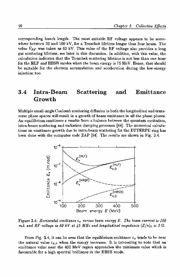
46 Chapter 9. Collective Effects
corresponding bunch length. The most suitable RF voltage appears to be somewhere between 20 and 100 kV, for a Touschek lifetime longer than four hours. The value VRF was taken as 60 kV. This value of the RF voltage also provides a long gas scattering lifetime, see later in this discussion. In addition, with this value, the calculation indicates that the Touschek scattering lifetime is not less than one hour for the HLF and HBSB modes when the beam energy is 75 MeV. Hence, that should be suitable for the electron accumulation and acceleration during the low-energy injection too.
3.4 Intra-Beam Growth
Scattering and Emittance
Multiple small-angle Coulomb scattering diffusion in both the longitudinal and transverse phase spaces will result in a growth of beam emittance in all the phase planes. An equilibrium emittance c results from a balance between the quantum excitation, intra-beam scattering and radiation damping processes [44]. The numerical calculations on emittance growth due to intra-beam scattering for the EUTERPE ring has been done with the computer code ZAP [54]. The results are shown in Fig. 3.4.
10-!l
,.....,. "0 0 .....
10-7 E ........ " (-.)
(Ll {.)
10-8 c:: 0 +' +J
E w
10-9
100 200 300 400 500 Beam energy E (MeV)
Figure 3.4: Horizontal emittance c:, versus beam energy E. The beam current is 100 mA and RF voltage is 60 kV at 45 MHz and longitudinal impedance IZ/nlo is 9 0.
From Fig. 3.4, it can be seen that the equilibrium emittance ex tends to be near the natural value cx,o when the energy increases. It is interesting to note that an emittance value near the 400 MeV region approaches the minimum value which is favourable for a high spectral brilliance in the HBSB mode.

9.5. Longitudinal Impedance and Beam Lifetime 47
3.5 Longitudinal Impedance and Beam Lifetime
From the discussion in Section 3.2, it is known that the influence of turbulent bunch lengthening depends mainly on the effective impedance of the ring. As the impedance increases, the electron bunches become longer and have a larger energy spread. That results in reduced intra-beam scattering and increased Touschek lifetime. The bunch length UL is almost the same in the two modes HBSB and HLF, see Fig. 3.5. On the other hand, the impedance has little influence on the emittance in the transverse direction, except that a short bunch length causes more intra-beam scattering and enlarges the transverse emittance. Hence, when a short bunch length is not important for synchrotron radiation, such as in the HBSB and HLF modes, a large longitudinal impedance may actually be advantageous for achieving a long bunch and a long lifetime.
.--.. Ul
10 100 .... ::l 0 __..... .c. E '--"
II) 8 80 E
~ ~
...J
b (!)
E 6 60 :;:::;
~ .::< 40 .c. (!) 4 (,) .c. c 0 ::l Ul !D :::l 0
1- 20 2 3 5 7 9 11
Longitudinal impedance IZ/nletf (0)
Figure 3.5: Bunch length and Touschek lifetime versus longitudinal impedance. The beam current is 100 mA at 4 00 MeV and RF voltage is 60 k V at 45 MHz.
3.6 Beam Current and Bunch Properties
Figure 3.6 shows the equilibrium emittance, bunch length and Touschek lifetime as functions of the beam current I in the EUTERPE ring. The results used in this figure were obtained from numerical calculations and the ZAP code taking into account both bunch lengthening and the intra-beam scattering. Below the threshold current Ibt,. , the bunch length is constant. Above Ibt~>, the bunch lengtq increases as the current increases. For the HLF mode, the emittance is almost constant with increasing beam current, which indicates that multiple small-angle Coulomb scattering is not serious in this case. However for the HBSB mode, the emittance becomes larger as the beam current increases, since the charge density in the bunch

48 Chapter 3. Collective Effects
10
-------.......... "'C 0 8 HBSB - --- ---L
E c
HLF (x25) ....._... 6
X w
.......... 4 (/) L :::J
4 0 ..c ....._...
.......... ., 2 " 0
t= ....... 0'1 0
0 .....J
60
.......... E 40 HLF E --....._... -- , ...J
b 20 _, /HBSB
0~------------.------.------------~ 0 ~ M 1~ 1W 200
Beam current I (mA)
Figure 3.6: Dependence of equilibrium emittance C:x, bunch length r:T£ and Touschek lifetime TTous on beam current I. (Longitudinal impedance IZ/nlo is 3 0. RF voltage is 60 kV at 45 MHz. Beam energy is 400 MeV.)
in the HBSB mode is much higher than that in the HLF mode. The emittance with a 200 rnA beam current is almost twice as large as the natural emittance. In addition, the beam lifetime TTous decreases as the beam current increases. The value of TTous
with 200 rnA is about one hour less than the value of TTous with 100 rnA for both modes.
3. 7 Gas Scattering and Beam Lifetime
In a storage ring, the stored beam scatters with the residual gas in the vacuum chamber. That scattering leads to an angular kick or an energy loss for the circulating particles. The scattered particles will be lost if they exceed the transverse or longitudinal acceptance of the machine. The beam lifetime that results from such

3. 7. Gas Scattering and Beam Lifetime 49
beam-gas interaction, is called the gas scattering lifetime. The gas scattering lifetime r9 is defined by the inverse of the relative rate of loss
[54]: 1 1 dN - = --- = (1'tCn9 , (3.7)
Tg N dt
where N is the number of circulating electrons, c the electron velocity, (Tt the scattering cross section for the electron losses and n9 , the density of the residual gas atoms.
At "room temperature" {T=300 K),
(3.8)
where nz is the number of atoms per gas molecule, P the residual gas pressure. Then, the gas lifetime can be expressed by:
(hours), (3.9)
where P is the residual gas pressure in Pascal. The equations above indicate that in order to increase the gas scattering lifetime,
the following three points are important:
• reducing the cross section for the electron losses;
• keeping a low residual gas pressure in the storage ring during the operation;
• selecting a suitable pumping system with a low partial pressure, especially for components of molecules with high atomic number.
There are essentially four processes in the beam-gas interaction [19], i.e., elastic scattering on nuclei (ESN), bremsstrahlung on nuclei (BSN), elastic scattering on electrons (ESE) and inelastic scattering on electrons (ISE). Correspondingly, the lifetimes are given by [19]:
(hours)
(hours)
(3.10) (hours)
(hours)

50 Chapter 3. Collective Effects
where {/3} is the average betatron envelope function, Z the atomic number of the residual gas species, c/ Eo the energy acceptance and 2b the diameter of the beam pipe.
It is obvious that the gas scattering lifetime depends a great deal on the vacuum conditions in the ring. Apart from this, the electron loss due to the BSN, ESE or ISE process depends mainly on the energy acceptance of the ring. For a pressure of 133 nPa (lo-9 Torr) in carbon monoxide gas, Eo=400 MeV and c/ Eo=0.5rv2.5% (considering that the RF voltage is 60 k V with 45 MHz, the size of vacuum chamber 2b is 2.3 em and the value of (/3} is between 5 and 8), the lifetimes are:
TUESN
TUBSN
TgESE
TgisE
Ri 7 "" 19 Ri 45""' 70 Ri 160""' 800 Ri 125,...., 220
(hours), (hours), (hours), (hours).
(3.11)
The electron loss due to the elastic scattering on nuclei is very dependant on the values of the beta function and on the size of the vacuum chamber and it is inversely proportional to the square of the electron energy. Since the EUTERPE ring is a low energy ring, ESN contributes most to 1/ru. Figure 3.7 shows the relative contributions of the various types of scattering to the lifetime in the case of the HLF mode. Because ESN depends very much on the f3 function of the lattice, the loss of the beam current is more serious in the HBSB mode, therefore, the gas scattering lifetime is only about half that for the HLF mode.
103 +-------~------~------~-----~-~-* ---------
7' gBSN
133 nPo CO gas 10°+-----L-,-------.-------.-------+
50 150 250 350 Beam energy E (MeV)
450
Figure 3.7: Lifetime resulting from the different processes of gas interactions for HLF mode.
Figure 3.8 shows the relationships between the gas scattering lifetimes and the electron beam energy for two optical modes providing the gas pressure is constant. In principle, if the energy acceptance increases, the gas scattering lifetime will also increase. However, increasing the energy acceptance will not help to increase the

3.8. Conclusion 51
15+-------L-----~------~-------+
HBSB_....... /
.~ 6
..... Cl.J /
/ --:s 3 -150 250 350 450 Beam energy E (MeV)
Figure 3.8: Gas scattering lifetime versus electron beam energy, assuming a pressure of 133 nPa of carbon monoxide gas. {At low energy, there is only thermal gas desorption and the gas pressure will be much less.)
gas scattering lifetime in the EUTERPE ring because r 11 is mainly determined by the elastic scattering on nuclei and the physical aperture of the EUTERPE ring.
The vacuum in an operational electron storage ring is mainly limited by photon stimulated desorption (PSD) originating from synchrotron radiation. A vacuum design was chosen for EUTERPE so that a partial carbon monoxide pressure of 133 nPa at 400 MeV with 200 rnA can be expected [36], assuming that the residual gas is mainly hydrogen and carbon monoxide. Generally, gas scattering from hydrogen can be neglected. Thus, the expected gas scattering lifetime should be ten hours in the HLF mode, see Fig. 3.8. During injection, the critical energy of synchrotron radiation is far below the 10 eV threshold for PSD. Then, the pressure in the machine will be limited only by the thermal gas desorption of the chamber walls. With a carbon monoxide partial pressure below 10 nPa in the HLF mode the gas scattering lifetime will be about four hours. ·
3.8 Conclusion
A study of the collective effects on the EUTERPE ring led to the following conclusiOns: 1. Using a 45 MHz and 20-100 kV RF cavity and the designed parameters of the lattice, the value of the horizontal emittance at 400 MeV with a 100 rnA beam current is near that of natural emittance and the smallest emittance of 8.5 nmra.d can be achieved in the high brilliance mode. 2. Under such conditions, the Touschek lifetime will be more than four hours in both the HBSB and HLF modes.

52 Chapter 3. Collective Effects
3. The electron loss due to gas scattering relies mainly upon the value of the betatron function of the lattice and the size of the vacuum chamber. With a partial CO pressure of 133 nPa at 400 MeV, the gas scattering lifetime is more than five hours in the HBSB mode and ten hours in the HLF mode. 4. For a short bunch length of a few mm in the SBL mode, the bunch current is smaller than 0.1 rnA. It will be necessary to use a much higher frequency system with a higher voltage (e.g. 300 MHz RF and 400 kV) if a single bunch with high current is required that exceeds 1 rnA with a length in the order of 1 mm. 5. When the beam energy is 75 MeV, the gas pressure in the machine will be limited only by the thermal gas desorption, and the gas scattering lifetime and Touschek lifetime can be more than one hour. Therefore, the collective effects will have no obvious adverse influence on low energy injection into the ring.

Chapter 4
Injection
In this chapter, injection into the ring is discussed. A procedure is presented for continuous injection with an adjustable locally shifted dosed orbit; that procedure is suitable for long injection pulses. The discussion also includes the injection elements and the beam transfer line of the EUTERPE ring, as well as the injected beam current characteristics and timing considerations for the pre-accelerators.
4.1 Introduction
Low energy injection is an essential aspect of small storage rings, especially small dedicated synchrotron radiation rings, because the price of the injector and the injection transfer line may be a substantial part of the total project cost. The injector of EUTERPE is a 75 MeV racetrack microtron (RTM) which is injected from a 10 MeV (medical) linac (type M.E.L. SL75/10). The beam current from the linac is too low to permit a single turn injection into the ring. In order to collect 200 rnA beam currents in the ring, multi-turn injection with an adjustable closed orbit was considered. The electron beam behaviour during the injection time has been simulated with the computer code DIMAD. The tracking results indicate that a small beam current from the injectors can be injected continuously into the ring in the low energy injection process [58].
Results of low energy injection studies for the EUTERPE ring are presented in the following sections. The injectors, beam transfer lines and injected beam current characteristics are described in Section 2. The details of the injection procedure are given in Section 3. The effects of energy spread, beam-gas scattering and intrabeam scattering at the low injection energy are given in Section 4. A suitable shift of the closed orbit during injection is a critical issue for successful injection in storage rings. Basic conditions for this shift and the choice of suitable kicker parameters are discussed in Appendix A.
53

54 Chapter 4. Injection
4.2 Injectors and Beam Transfer Lines
The main injection elements of the EUTERPE ring are a 75 MeV RTM, a 10 MeV linac and two transfer lines, which are shown in Fig. 4.1.
Figure 4.1: A general view of the linac, the RTM and transfer lines. (For a top view, see Fig. 2.1.)
The racetrack microtron consists of two 180° bending magnets and a 5 MeV RF standing-wave accelerating cavity [59, 60]. The bending magnets are separated by a field-free region of about 1 m along the cavity axis. The electrons are injected with a kinetic energy of 10 MeV. Each passage of the accelerating structure gives them an energy gain of 5 MeV. After 13 successive turns, the electrons are extracted. Details of this can be found in reference [60].
The linac consists of an electron gun, a magnetron for RF power and a disk loaded travelling wave guide accelerator. It provides 50 pulses per second with a pulse current of 30 rnA and a macro-pulse duration of 2.2 J.lS. The RTM and the linac have the same operating frequency of 3000 MHz. The electron beam emittance coming out of the linac is approximately 9 mmmrad at 10 MeV, and the relative energy spread about 10%. However, a substantial amount of current will be lost since the RTM can only accept particles with an energy spread of less than 1%. The energy spread of the extracted beam from the RTM was estimated to be 0.15% [60]. The main parameters of the RTM and the linac are listed in Table 4.1.
A transfer line transports the electron beam from the linac to the RTM. It is an antisymmetrical system with double achromatic behaviour and consists of four identical 50 degree bending magnets, preceded by a quadrupole triplet and followed

4.2. Injectors and Beam Transfer Lines 55
Table 4.1: Main parameters of linac and RTM.
Linac RTM Injection Energy 10 MeV Extraction Energy 10 MeV 75 MeV Average Pulse Current 30mA 6 rnA a
Energy Spread 10% a 0.15% Pulse Duration 2.2 JLS 2.2 JLS RF Frequency 3000 MHz 3000 MHz
" Estimated value.
by a quadrupole doublet in order to provide adequate focusing [61]. The beam is lowered by 40 em in the vertical plane when it is transported from the linac into the RTM.
Another transfer line transports the electron beam from the RTM to the storage ring at the same vertical elevation. It consists of two double achromatic bending sections and two quadrupole doublets [62]. The first bending section comprises two dipoles and one quadrupole. It forms a complete double achromatic system together with the last bend in the RTM. The beam is extracted from the RTM at an angle of approximately six degrees with respect to the cavity axis, and is bent through the first bending section to become parallel to the cavity axis at a distance of 15 em away from the dipole magnet of the RTM. Then, the beam is bent through the second achromatic section towards the ring. The second bending section comprises two identical dipoles with a symmetrical quadrupole triplet between them. One quadrupole doublet connects the two bending sections. Another quadrupole doublet follows the second bending section in order to match the injected beam shape in the phase space of the ring at the injection location. The angle between the transfer line and the ring is 11.5°. This remaining bend of 11.5° is accomplished by a magnetic septum and an electrostatic septum. The magnetic septum has an effective length of 10 em, a deflection angle of 175 mrad corresponding to a magnetic field of 0.45 T. The electrostatic septum has an effective length of 30 em, a deflection angle of 25 mrad corresponding to an electric field of 63 kV /em at 75 MeV [58].
It is expected that a 200 rnA stored electron beam will exist in the ring. The beam current of 200 rnA is equivalent to 1.66 x 10¹¹ electrons circulating in the ring. The linac output is a 30 rnA macropulse current, where the macropulse is 2.2 p,s long with a pulse repetition frequency of 50 Hz which implies 4.2 x 10¹¹
electrons per pulse. Thus, the number of electrons in one linac pulse will exceed the number of accumulated electrons in the storage ring at 200 rnA by a factor of 2.5. Unfortunately, not all of them can be used. As mentioned above, the energy spread of the electron beam coming from the linac is too large to be accepted by the microtron. It was estimated that about 20% of the electrons can be accepted by the RTM. (This will be done deliberately with a diaphragm placed in a dispersive

56 Chapter 4. Injection
section of the beam guiding system from the linac to the RTM in order to prevent any significant beam losses in the RTM itself). This means that four linac pulses will be needed to accumulate 200 rnA, assuming 50% injection efficiency in the ring and using the full 2.2 JJS injection time of each pulse. Since the electron revolution frequency in the ring is 7.5 MHz, it implies that a 16 turn injection will be needed for each linac pulse. This is feasible with an excellent beam emittance from the linac and microtron and a suitable injection procedure.
4.3 Injection Procedure
Injection into the ring takes place in the horizontal plane. The electrostatic septum is put into the centre of one long straight section where the horizontal beta-function has maximum value. In order to inject the electron beam easily for different optical modes, a group of four kickers or bump magnets is used to shift the closed orbit in the horizontal direction during the injection time. The necessary conditions for the closed orbit shift and the related parameter selection can be seen in Appendix A. The kickers are inserted symmetrically with respect to the injection septum's position. A shifted closed orbit will be parallel to the reference closed orbit at the septum's position. The details of the injection procedure are explained below. Firstly, multiturn injection is described with a fixed locally shifted closed orbit using fast kickers, it is suitable for a short duration of the injection pulse. Then, continuous multi-turn injection is described with a varying shifted dosed orbit, it is suitable for a long duration of the injection pulse as delivered by the pre-accelerators.
4.3.1 Multi-turn Injection with a Fixed Locally Shifted Closed Orbit
Prior to injection, the kickers are switched on. The normal closed orbit is displaced from the reference orbit (corresponding to the centre of the beam pipe) to a new position near the septum. Figure 4.2 shows this for the HLF mode. There, the deflection angles of the kickers are 2.35 mrad for both K1 and K4, and 4.80 mrad for K2 and Ka. The beam is injected along the axis in the vertical plane and away from it in the horizontal plane; the separation is -21.5 mm with respect to the reference closed orbit. After being injected into the ring, the electrons perform a horizontal betatron oscillation around the displaced orbit.
Figure 4.3 shows the evolution of the emittance figure for the injected beam in the horizontal phase space, which was obtained by a tracking simulation. It has been assumed that the emittance of the injected beam was 0.6 mm.mrad with a rhombic shape. From Fig. 4.3, it is obvious that the injected beam will hit the septum after five turns. If the fast kickers are switched off between the fourth and fifth turns, the shifted dosed orbit rapidly returns to the original reference orbit (see Fig. 4.2 and Fig. 4.3). Then, the elliptic phase space contour, containing five rhombuses and centred around the displaced closed orbit, moves away from the septum. From Fig. 4.3 it can be seen that no particle will hit the septum during continuous injection of 5

4.3. Injection Procedure 57
K1 K2 K3 K4
__...._ 0 +---""""'---------------E E
reference orbit
'-"'
X
...... c: Q)
displaced orbit
E Q) u 0 0.. (/)
injection beam septum
12 14 16 18 20 22 24 26 28 Longitudinal coordinate s (m)
Figure 4.2: The shifted closed orbit.
turns, i.e. 665 nanoseconds. After the kickers are switched off, the injected electrons will remain in the ring, moving along the elliptical contour in phase space. Due to synchrotron radiation damping, the horizontal phase space -eontour will shrink in size to the natural emittance. Therefore, after a certain damping time (a number of seconds for the EUTERPE ring) the kickers can be switched on and the five turn injection procedure can be re-started.
Generally, if the displaced orbit is close to the septum, the elliptic contour in Fig. 4.3 will be small, hence, also, the horizontal oscillation amplitude of injected electrons will be small. This is an advantage regarding the distortion of the closed orbit and the aperture limitation of the ring. However, strong kickers are required for this and the size of the elliptic contour may be too small as compared with the phase space area of the injected particles. This means that injected particles may collide with the septum. Therefore, a trade-off needs to be made between the specific position of the displaced orbit and the size of the elliptic contour.
In principle, this injection procedure can be repeated until the required number of stored particles is obtained. However, it is really only suitable for short pulses of a few revolution periods. Otherwise, the effectiveness of the injection will be poor, as is the case for EUTERPE, where the linac provides pulses of 2.2 f..tS that are equivalent to about 16 revolutions in the ring. For that reason, an alternative method had to be investigated, as described in the next section.

58 Chapter ,j. Injection
24-----~----~----~------L-----~----~
ll) u c ll) en ..... ~ -1 a
septum 3
oE/E=O
oE/E=+0.5%
oE/E=-0.5%
0
• displaced orbit o reference orbit
-24------.------.-----~----------~r-----+ -25 -20 -15 10
Displacement x -5 (mm)
0 5
Figure 4.3: The evolution of the emittance area of the injected beam. The numbers 0, 1, 2, etc. refer to the revolution number with respect to the start of the injection.
4.3.2 Continuous Injection with an Adjustable Locally Shifted Closed Orbit
Figure 4.4 illustrates the continuous injection procedure. At the beginning of the injection, the closed orbit shifts to Position 1. After five revolutions, the five rhombuses in the phase space are filled with electrons. Then, the displaced orbit moves quickly from Position 1 to Position 2. Thus, the injected electrons continuously fill another five rhombuses with a larger elliptical contour centred around the displaced orbit. Repeating this, the dosed orbit moves from Position 2 to Position 3 after another five revolutions, and so on. Thus, the electrons in one linac pulse are injected into the ring during fifteen revolutions. As soon as all these electrons are in the ring, the kickers are switched off. Then, the closed orbit will return to the reference orbit. As in the fixed locally shifted dosed orbit procedure, phase space contours will shrink to the size of the natural emittance due to synchrotron radiation damping. After that, a new injection procedure can start with a new 2.2 p,s pulse from the injector system.
In practice, for technical reasons, the strength of the kicker field will be linear with time and will vary from large to small, in order to obtain the closed orbit shifts. Consequently during the injection time, injected particles will move along a spiral in the transverse phase space with a centre moving towards the reference closed orbit. Figure 4.5 shows the required timing sequence for an injected electron pulse and for the magnetic kicker field. Related parameters for the kickers are given in Table 4.2.

4.3. Injection Procedure
2+-----~------~-----L----~------+
X
~ 0 c: Q)
e' ~ -1 6
After 5 turns
septum
-24-------.-----~------.-------.------+ -25 -15 -5 5 15 25
Displacement x (mm) 24-------L-----~------~------~-----+
·x Q) 0 0 c: Q) 0'1 .... ~ -1 6
After 10 turns
septum -2+-----~-------r------~----~~----~
-25 -15 -5 5 15 25 Displacement x (mm)
2+-----~~----~------~----~~----~
·x Q) 0 0 c: Q) 0'1 .... Q) -1
.?! a
After 15 turns
-24-------~------r-----~------~------~ -25 -15 -5 5 15 25
Displacement x (mm)
59
Figure 4.4: Evolution of the injected beam after 5, 10 and 15 turns with an adjustable locally shifted closed orbit scheme.

60 Chapter 4. Injection
Table 4.2: Kicker Parameters.
Quantity 4 Deflection 0-5 mrad Magnetic Field 0-12 mT Pulse Duration 2.2 J.tS Effective Length 10 em
~
-
/ // 0
Figure 4.5: The diagram for the timing control.
4.4 Effects of Energy Spread, Gas Scattering and Intra-beam Scattering on the Injection Process
For the injection of EUTERPE, an aluminum foil in front of the electric septum will be used to separate the storage ring vacuum system with a designed pressure of 133 nPa (10-9 Torr) from the vacuum system of the microtron and the transfer line with an estimated pressure of 1.33 x 10⁻⁴ Pa (lo-6 Torr). However, that will give a slight increase to the energy spread of the electron beam. Electrons with a definite energy passing through a foil lose energy as a result of inelastic collisions with atomic electrons and the emission of bremsstrahlung in the Coulomb field of the nuclei [63].

4.4. Effects of Energy Spread, Gas Scattering and Intra-beam Scattering on the Process 61
Due to the randomness of the energy losses, electrons will have a spectrum of energies after travelling through the foil, which will contribute to an extra energy spread of the injected electron beam coming out of the RTM. According to the calculation of electron energy-loss spectra given by McLellan et al. [64], this extra energy spread for 75 MeV electrons was estimated to be less than 0.3% assuming that the thickness of the aluminum foil is 0.1 mm.
In the tracking simulation a given momentum spread ( oE / E ±0.5%) was taken into account. From Fig. 4.3, it can be seen that the behaviour of the electrons is only slightly changed during the injection process. This means that off-energy particles within 6E/ E = ±0.5% are all accepted by the ring, indicating that the momentum spread is insignificant as far as the EUTERPE injection is concerned, the estimated energy spread from the RTM and foil scattering being less than 0.5%.
At low energy, radiation damping rates are usually small. From Eq. (2.39), the transverse damping time for the EUTERPE ring is about seven seconds at an injection energy of 75 MeV. Taking that damping time as the time interval for injection pulses, the total injection of electrons with four pulses will be completed within one minute. From the discussion in Chapter 3, it can be concluded that the Touschek scattering lifetime is more than one hour and the gas scattering lifetime about four hours at 75 MeV. That is long enough for the injection procedure and acceleration to reach 400 MeV. Therefore, gas scattering and intra-beam scattering will have no obvious adverse effects on low energy injection in the ring.

Chapter 5
Bypass Line and Bunch Combination
A bypass system added to a normal electron storage ring offers an excellent opportunity for the installation of a free electron laser with a small aperture undulator. At the same time, when the bypass system obeys certain conditions it can be used to manipulate the bunches in such a way that all or most bunches can be combined. This then results in an intense single bunch circulating in the ring. Aspects of such a bypass system are treated in this chapter.
5.1 Introduction
The aim of a bypass system is to provide a transfer line for a Free Electron Laser (FEL) system where coherent radiation in the XUV region can be produced [65]. For the FEL studies, an undulator with an aperture of 5 to 10 mm and a length longer than 6 m was considered (66]. From the discussion in Chapters 2 and 3, it can be imagined that when an undulator with such a small aperture is placed in a normal section of the ring, the effective aperture of the ring will be reduced substantially and the beam lifetime becomes poor. Moreover, an interaction of the beam with the FEL undulator is disruptive to the quality of the beam itself, mostly in terms of energy loss and increased momentum spread. This problem can be overcome if the FEL undulator is placed in a special bypass line [67]. A beam of good quality in the normal ring can be guided into the bypass line where the interaction with the undulator takes place. Intense, coherent radiation is then generated. After the beam leaves the undulator, it is deflected back into the storage ring, where synchrotron radiation damping restores the beam quality. After a few damping times, the beam is ready to be guided again into the bypass line.
The bypass line also provides sufficient space for other devices to be tested without disturbing the main machine operation; for example, high field (superconduct-
63

64 Chapter 5. Bypass Line and Bunch Combination
ing) wiggler systems, optical klystrons, etc. In general one can also test devices longer than those that can be accommodated in the long straight sections of the ring, or the devices with a very small aperture. With a bypass, the ring can be seen as a combi~ation of two separate rings. The normal ring functions as a booster synchrotron and damping ring. The ring enlarged by the bypass line forms the FEL-storage ring.
Furthermore, a bypass provides an opportunity for combining and manipulating bunches [68]. As mentioned in Chapter 1, the number of bunches is very often equal to the harmonic number of the RF system. Then the time interval between the synchrotron radiation pulses is determined by the RF frequency. For a longer time interval, selective injection or single bunch injection is needed [69]. For storage rings, manipulating the number of bunches is often needed for different reasons. One reason is to get a single bunch operation. Another reason is to increase the single bunch current if the injector of the storage ring is not suitable for single bunch injection [70]. In some cases, it is necessary for improving the beam stability or for producing radiation pulses with a selected periodicity[69]. For manipulating bunches, different methods have been used. One of them is the "knock-out" method [69] that results in an equivalent loss of beam current. Other methods make use of multiple RF systems [69, 71] or of a special booster [70, 69]. A method for combining bunches using a bypass system for an electron storage ring is suggested in reference [68]. It permits high bunch currents to be achieved and can be used to produce radiation pulses with a selected periodicity for specific synchrotron radiation usage. A bunch extraction method that utilizes coherent transverse betatron oscillations with small kicks is discussed in this chapter as well as the design of the bypass system.
As an example of the potential of the bypass system for EUTERPE, the wavelength of the generated radiation using the TEUFEL-undulator [72] is mentioned. This undulator, designed and constructed by the Twente group, has a period of 25 mm and a gap of 8 mm with a peak field of 0.6 T. The emerging radiation is 40 nm, it is proportional to the undulator wavelength and inversely proportional to the square of the electron energy. The intensity of the radiation depends on various factors, e.g. the number of undulator periods and the electron beam quality. The photon beam characteristics can be calculated with the existing computer programs [73].
5.2 Bypass Line
The following conditions are necessary for the bypass line added to the ring:
• The total length of the bypass line and the related normal ring part, Ltotal, must satisfy:
Ltotal = nL/h, (5.1)
where n is an integer, L the circumference of the normal ring (e.g. 40 m for EUTERPE) and h the harmonic number.

5.2. Bypass Line 65
• A long straight drift section with zero dispersion should be provided.
• The optical elements must allow easy adjustment of the beam size and divergence in the long drift section.
B
Q8 07
B
Bp2
Qp5
Qp6 Qp7
Qp7 Qp6 Qp5
Figure 5.1: Layout of the suggested bypass line connected with the EUTERPE ring.
Synchronism with the RF is automatically obtained when Eq. (5.1) is satisfied. In order to get zero dispersion in the long straight section, double achromatic bending sections are needed for transferring the electrons from the ring to the long straight section. Adjustment of the beam behaviour in the long straight section can be achieved with a quadrupole group put at each end of the long straight section, such as a doublet or a triplet.

66 Chapter 5. Bypass Line and Bunch Combination
Figure 5.1 shows a suggested bypass line and the related elements in the EUTERPE ring.
Table 5.1: Main parameters of optical elements in the bypass line.
Element Length Bending angle lnduction./Strength Number Bv, a 0.500 m -20° -0.931 T 2
BP2 0.900 m 55° 1.423 T 4
QP1 b 0.274 m - 3.400 m ·2 2
Ql'2 0.274 m -4.323 m ·2 2 Qp~ 0.274 m 5.536 m- 2 2 Q!), 0.274 m - 5.623 m- 2 2 QP.s 0.274 m - 2.436 m- 2 2 Qpe 0.274 m - -5.364 m .-, 2
QPT 0.274 m - 2.133 m ·2 2
a B- Dipole magnet; b Q - Quadrupole magnet.
60+-------~------~------~------~------+
40
':() 20 0 ..._ ~ E
-.....,.;
-20+-------~------~----~------~------~
0 10 20 30 40 50 S (m)
Figure 5.2: Betatron and dispersion functions for EUTERPE with the bypass line.
The whole system consists of two identical bending sections, two quadrupole triplets and one long straight section. Each bending section comprises three bending magnets and two quadrupole doublets. The bending sections connect the normal ring and the bypass line via two septa, namely septum ext and septuminj. Both

5.3. Bunch Combination 67
septa are placed in the long straight sections of the ring, see Fig. 5.1. One is used to extract the beam from the normal ring into the bypass line, and the other one is used to re-inject the beam from the bypass line into the ring.
Table 5.2: Lengths of drift sections in the bypass line.
Length (m) Number 2.060 2 0.250 2
2 2 2
0.250 2 2 2
The total length of the bypass line and the related normal ring part is 46.666 m. The bypass provides a 7.8 m long straight section that can be used for tests of various types of undulators. Between this long straight section and the bending sections, two quadrupole triplets are used to focus the beam in accordance with the requirements of test devices in the straight section. Then the betatron functions at the entrance (or exit) and middle of the straight section can be easily adjusted. As an example, Fig. 5.2 shows the electron optical performance of EUTERPE with the designed bypass line in the HBSB mode, where the beam size is nearly constant in one direction and is very small in the other direction along the long straight section. Table 5.1 gives the related parameters of the bending magnets and quadrupoles which are inserted in the bypass line. The drift lengths of the bypass section are given in Table 5.2. An electrostatic septum with a length of 30 em and a gradient of 130 kV fern should be adequate to provide an angular kick of 9.8 mrad, which will give a beam separation of 1 em at the magnetic septum Bp1 as the distance between the electrostatic septum and the magnetic septum is about one meter.
5.3 Bunch Combination
5.3.1 Basic Conditions
The realization of combining bunches with a bypass relies on the path length difference for the two bunches to be combined and on synchrotron radiation damping. Both a fast extraction kicker and a fast re-injection kicker in the ring are required, as well as two septa for extraction and re-injection. For combining the bunches without losing particles, the following three conditions need to be fulfilled:

68 Chapter 5. Bypass Line and Bunch Combination
• The difference in length between the bypass line Lbypau and the bypassed storage ring section Lpaued should be about equal to the separation between the two bunches that are to be combined.
• The timing for firing the extraction and re-injection kickers must be in accordance with the combination process.
• During the combination process bunches need to be kept within the effective machine aperture. The transverse apertures are mainly determined by the ejection and re-injection system. In the longitudinal direction, the combination is automatically satisfied by the condition in Eq. (5.1).
At a certain time, the extraction system extracts a bunch (or several bunches) into the bypass line but leaves the remaining bunches undisturbed. After a time Lbypaufc, the bunch travelling through the bypass line is re-injected into the storage ring and combined in the transverse phase space with the bunch which moved along the by-passed ring section. Afterwards, these two bunches will merge through radiation damping. Then a new bunch combining process can start. In that way, all the bunches circulating in the storage ring can be combined into several bunches or a single bunch.
Figure 5.3: Evolution of the beam bunches during the combination process.
In the case of EUTERPE, the length difference between the bypass line and the by-passed storage ring section is 40/6 m. Normally the number of bunches in the

5.3. Bunch Combination 69
EUTERPE ring is six. The bunch spacing or separation in the longitudinal direction is 40/6 m or 133/6 ns. Using the method mentioned above, Fig. 5.3 shows how two bunches can be combined together. The time step is taken as D..t = 133/6 ns.
By manipulation, the combination process can be repeated until the bunch spacing is increased by two or six times the original spacing. Then, synchrotron radiation pulses will be produced with a corresponding time interval.
5.3.2 Extraction and Injection Method
In order to combine bunches with the bypass line, an unusual particle extraction method has been considered. It is based on the excitation of a small coherent transverse betatron oscillation for a single bunch, using a small amplitude fast kicker.
Suppose that a kicker Ke, put at a position SKe, gives a kick 6ke to a particular bunch at a certain time; then, the bunch will perform a betatron oscillation around the normal closed orbit (reference orbit). At position Se (entry to the extraction septum), the coordinates of the kicked bunch can be obtained from Eqs. (1.15) and (1.16):
(
Vf3s.f3sKe sin</Je/Ke )
{li:: . Dke, v 73:;;( COS <Pel K e - as. Sill </Je; K e) (5.2)
where <Pe!Ke = <P(se) - </>(sKe) is the phase advance from the kicker Ke to the extraction septumext.
From this equation, the smallest kicker strength necessary to induce the required displacement is found for a phase advance <Pe;Ke of 27r(n + 1/4) (n = 0, 1, 2, 3, · · ·) between the kicker Ke and septumext, and for large values of the beta-function at these elements. For convenience, the kicker Ke should be put just in front of the septum (see Fig. 5.1), where the beta-function has its maximum value. Furthermore, the tune has to be adjusted to near <Pe/Ke/(27r)=n + 1/4. In such a case, after one revolution, the displacement of the kicked bunch will be Ys. ~ f3s.Dke and ifa. ~ 0 for as. ~ 0. Then, the kicked bunch enters the bypass line via septumext. After it returns to the ring from the bypass line via septuminj, the re-injected bunch will perform a betatron oscillation around the reference orbit of the normal ring with amplitude Ys; which is the displacement of the re-injected bunch at s;, the exit of septuminj (Normally, the divergence Yo; can be adjusted to zero.). The amplitude of the betatron oscillation needs to be reduced quickly to allow the re-injected bunch to circulate safely in the normal ring without colliding with the wall of the septa; therefore, a fast kicker K; needs to be used. Suppose that K; is inserted at a position SKi, then the coordinates of the re-injected bunch at SKi will be given by (from Eqs. (1.15) and (1.16)):

70 Chapter 5. Bypass Line and Bunch Combination
From Eq. (5.3), it can be seen that the smallest kicker strength needed to realize this reduction can be obtained if kicker Ki is put at a position SKi with a large value of the beta-function (3,Ki and a phase advance of tPKi/i = m1r /2 (m = 1, 3, 5, · .. ).
It should be kept in mind that when the re-injected bunch gets a kick 6ki from kicker K;,, the bunch being combined with the re-injected bunch will get a similar kick oki from kicker Ki. In order to ensure that both of the combined bunches have small betatron oscillations, the value of 6ki should be smaller than y,Jf3,,.
I I I I ! I
extraction injeetion I I
~~~~--~--~~~1-T_o_lr---T-o--~J~--~t
Figure 5.4: Timing sequence.
In order to get a clear insight into the combination process, the evolution of two bunches I and II in horizontal phase space during the combination process was investigated with a tracking simulation of the HBSB optical mode. Figure 5.4 shows the timing sequence required for the kick actions, the bunch extraction, and the reinjection. It is assumed that septumei/Jt and septuminj are 7 mm from the reference orbit of the ring. For convenience, the kicker Ki is put just behind septuminj, see Fig. 5.1. For this configuration, the evolution of Bunch I and Bunch II in the phase space at the extraction septum se is shown in Fig. 5.5. In that figure, the numbers 1, 2, 3, ···refer to the revolution numbers. At a certain time denoted by point 0 in Fig. 5.5, a kick of 0.4 mrad is induced on Bunch I, while it passes through the kicker Ke at position BKe· Immediately, Bunch I jumps from the reference orbit to the big elliptical contour in the phase space, as shown in Fig. 5.5. After one revolution, Bunch I arrives at Position 1 where it comes into septumei/Jt and is guided into the bypass line. After it passes through the bypass line, Bunch I arrives at the position

5.3. Bunch Combination 71
0.6,_----~------~----~------~----~------~
0
0.3
....... "0 0 '-E 0.0 ...__,
X
-0.3
• Bunch Septum ext
-0.6 -12 -8 -4 0 4 8 12
X (mm)
Figure 5.5: Evolution of bunch I and bunch II in phase space at the extraction septum position.
of septuminj where it returns into the ring and meets Bunch II. Until that time, Bunch II stayed at the reference orbit in the phase space. Then, one revolution later, both Bunches I and II get an angular kick of 0.2 mrad from kicker Ki and jump to positions on the small elliptical contours in the phase space (from the reference orbit for Bunch II and from the big elliptical contour for Bunch I). From then on, as shown in Fig. 5.5, both bunches move along small elliptical contours in the phase space and stay within the aperture of the machine each time they pass the position of the septum. Later, both bunches will gradually merge and shrink into one bunch in the phase space due to radiation damping.
In order to extract Bunch I, a sequence of fast small kickers can also be used with a period that is an integral multiple of the revolution time To. A numerical calculation showed that, with 6ke = 0.1 mrad and a period of 4To, Bunch I can be extracted into the bypass line after 12+1 revolutions (extraction takes place one revolution after the last kick action, similar to the previous extraction procedure). After Bunch I has been re-injected into the ring, a kicker strength 6ki of 0.1 mrad will be needed to reduce the amplitude of its betatron oscillation.
The realization of bunch combination described above relies on the technology of a fast kicker system, in practice. A low-cost high voltage fast kicker system has been suggested [68]. The feasibility of such a system is discussed in Appendix B. Such techniques make it possible to combine all bunches into a single bunch within a few seconds for the EUTERPE ring.

Addendum
Dipole Magnet
The dipole magnets of the EUTERPE ring have some unconventional characteristics. The main parameters and the design of the dipole magnets are discussed. Mechanical tolerances are given, following from the electron optical calculations. The measurement method and magnetic performance of the prototype dipole magnet are presented.
1 Introduction
A C-configuration with parallel end faces has been chosen for the bending magnets. This configuration is beneficial for the emerging synchrotron radiation. Laminated rectangular blocks of transformer steel are cemented together. The pole faces are flat. The magnet's design is based on the computer code POISSON [74]. A prototype magnet was made by the CTD. Its magnetic performance has been determined with NMR equipment and a Hall probe system. The integral fields have been determined with a so-called "banana shape" coil measuring device [75].
2 Design of Bending Magnet
2.1 Main Parameters and Characteristics
In the philosophy of the EUTERPE project an attempt has been made to store 400 MeV electrons by using rather small bending magnets. Three major parameters of the magnets, i.e. the magnetic rigidity, the magnetic gap and the effective length of the magnet were decided by the basic restrictions of the ring design, see Chapter 2. For easy installation and servicing of vacuum chambers with their synchrotron radiation ports, C-type bending magnets are usually used for storage rings. In the present design, rectangular block shaped C-magnets have been used. This has two
73
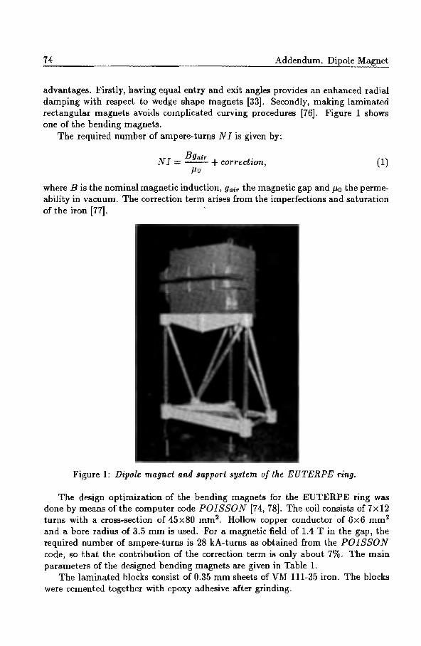
74 Addendum. Dipole Magnet
advantages. Firstly, having equal entry and exit angles provides an enhanced radial damping with respect to wedge shape magnets [33]. Secondly, making laminated rectangular magnets avoids complicated curving procedures [76]. Figure 1 shows one of the bending magnets.
The required number of ampere-turns N I is given by:
Bgair . N I ::::: -- + corredwn,
J.to (1)
where B is the nominal magnetic induction, Yair the magnetic gap and J.to the permeability in vacuum. The correction term arises from the imperfections and saturation of the iron [77].
Figure 1: Dipole magnet and support system of the EUTERPE ring.
The design optimization of the bending magnets for the EUTERPE ring was done by means of the computer code POISSON [74, 78]. The coil consists of7x12 turns with a cross-section of 45x80 mm2• Hollow copper conductor of 6x6 mm2
and a bore radius of 3.5 mm is used. For a magnetic field of 1.4 Tin the gap, the required number of ampere-turns is 28 kA-turns as obtained from the POISSON code, so that the contribution of the correction term is only about 7%. The main parameters of the designed bending magnets are given in Table 1.
The laminated blocks consist of 0.35 mm sheets of VM 111-35 iron. The blocks were cemented together with epoxy adhesive after grinding.

Addendum. Dipole Magnet 75
Table 1: Main parameters of the bending magnets.
Size 480x350x390 mm;:s Total weight 600 kg Bending radius 1m Sagitta 34mm Effective length 516mm Pole size 120x480 mm:l Gap height 25mm Coil cross section 45x80 mm:l Number of turns 2 X 84 Coil weight 20 kg Magnetic field (75 MeV) 0.25 T Magnetic field ( 400 MeV) 1.35 T Excitation current ( 400 MeV) 170 A Excitation power ( 400 MeV) 6kW Flow of cooling water 4 litres/minute
2.2 Field Errors
The field errors of bending magnets generally come from the manufacture process, instabilities in the electric power supply and from the temperature changes.
According to the lattice design, all bending magnets should have equal magnetic performance at any time during the machine's operation. One important parameter of the magnetic performance of a dipole magnet is its bending strength which is defined by:
Fo,o= J Bz(O,O,s)ds::BLejf, (2)
where the integral is taken along the reference closed orbit over the whole magnetic field range of the dipole magnet, Bz(O, 0, s) is the magnetic induction at the longitudinal position s in the magnetic median plane, B is an average value and Lef f is the effective field length of the magnet. When a particle with a momentum P passes through the bending magnet, Fo,o determines the total bending angle (}0 of the trajectory by
J Foo Oo = dO= (P}e)" (3)
For an insight into the influence of the bending strength on the closed orbit, two situations have been considered. In the first situation, it was assumed that all dipole magnets have the same deviation ~Fo,o/ Fo,o. In the second situation, it was assumed that the deviations of ~Fo,o/ Fo,o are randomly distributed along all

76 Addendum. Dipole Magnet
Table 2: Closed orbit distortions for particular source of error in bending magnets.
Error X eo( max) Xco(rms) Zeo(max) Zco(rms)
~ mm mm mm mm ll.Fo o/ Fo,o = 5x 10-o 0.04 0.03 - -
ll.Fo o/ Fo o = 5x 10 -o 0.03 0.01 H u(ll.Fo,o/Foo) = 5x10⁻⁴ 2.3 1.1 HLF u(ll.Fo o/ Fa o) = 5x 10⁻⁴ 2.5 0.9 - - HBSB
Uz = 0.2 mm 0.0 0.0 1.3 0.5 HLF Uz 0.2mm 0.1 0.0 1.5 0.6 HBSB u8 = 0.2 mm 0.5 0.2 0.0 0.0 HLF Us 0.2mm 3.9 1.4 0.0 0.0 HBSB uw = 0.2 mrad 0.0 0.0 1.3 0.5 HLF u.p = 0.3 mrad 0.1 0.0 1.6 0.6 HBSB
dipole magnets, with a standard deviation u and truncated at 2u. Table 2 gives the numerical simulation results. It can be seen that if the distortion of the closed orbit needs to be controlled within a few mm, u(ll.Fo,o/ Fo,o) has to be less than 5x10⁻⁴ . Therefore, the manufacturing process should ensure that all magnets have identical shape, especially the gap height and the length of the pole surface, since ll.Fo,o/ Fo,o = ll.gai.r /Yair + ll.Lef J / Lef J. Asking for a tolerance of 0.025 mm in the gap height is not realistic, although it contributes to the value of ll.Fo,o/ Fo,o by only 0.025/25 = 1 x 10⁻³ . Therefore, shimming plates at the pole ends will have to be used to adjust the magnet's length in order to compensate for errors in the gap height. Since an adjustment of 0.1 mm is not difficult, the tolerance for the effective length of bending magnets can be within 0.1/516 ~ 2x1o-4 .
For misalignment of the dipole magnets, the more sensitive ones for deviations of the closed orbit are misalignments in the longitudinal and perpendicular directions and rotation around the longitudinal axis. Taking a random distribution for these errors, truncated at 2u, numerical simulations indicated that the tolerance for these alignments need to be less than u 0.2 mm (or mrad) to ensure the possible deviations of the closed orbit are within a few mm, see Table 2. For positioning the dipoles, a novel support system integrated with a six degrees of freedom manipulator was developed by the CTD [76]. Displacements within ±5 mm with an accuracy of 0.02 mm are allowed in all three dimensions and rotations within ±1° with an accuracy of 0.005°. The mechanical stiffness of the adjustable support rods predominantly determines the stiffness of the support system. The ends of these rods are attached between the mass of the magnet and the outside world by means of "elastic hinges". Because of thermal effects, the mechanical dimensions of the magnet and its support system can change by up to 0.5 mm. Such changes may result in excessive mechanical forces which can cause possible plastic deformation and/or creep effects in the mechanical elements of the system. Because of this, di-

Addendum. Dipole Magnet 77
mensional changes and inaccuracy will occur. Therefore the magnet was attached to the support system with three leaf springs. The orientation of these springs is such that the relative position of the magnet with respect to the support system remains the same. The same mechanical design concept has been chosen for the attachment of the support system to the ground. Mechanical stability is determined with the dimensioning of the stiffness of the support system. A theoretical mechanical resonance frequency of 15Hz in all directions was chosen (the mass of the magnet is 600 kg). The prototype was measured and the actual resonance frequency found to be 14Hz. Combined with the supposed mechanical noise level of the laboratory these results are adequate for a good dynamical tolerance of place and stability of the dipole mass.
A variation in the bending strength is equivalent to a variation in the excitation current. The beam sizes in the bending magnets varies between 0.4 and 0.9 mm for the HLF mode and between 0.06 and 0.08 mm for the HBSB mode (confer Chapter 2). From Table 2, it is seen that if all dipoles have the same deviation !::,.Fo,o/ Fo,o = 5 x 10⁻⁵ , the deviations of the closed orbit will be about 0.0 0.04 mm for the HLF mode and 0.0 - 0.03 mm for the HBSB mode. In order to ensure the stability of the beam position to be within about 1/10 of the beam size, the stability of the excitation power supply needs to be 5 x I0-5 for the HLF mode. For the HBSB mode, the same stability of the closed orbit needs a stability of 1 x w-5
for the power supply. A novel distributed power supply system has been suggested [79). The system consists of a series connection of alternately power supplies and magnets. It combines the advantage of one big power supply with the same current through all coils with that of separated power supplies with a low voltage hence low leakage current flowing through the cooling system to earth. The stability of the current will be 1 x 10⁻⁵ . With that system, the individual bending strength adjustment of dipoles (after the shimming plates correction) can also be provided by small individual current sources (adjustable range = ±200 rnA) without additional coils. In addition, as individual power supplies have extra power capacity, failure of a single unit will be corrected by the others, which means a large overall reliability of the system.
3 Measu~ing Methods
3.1 Measuring Set-up
For the magnetic field measurements, a Nuclear Magnetic Resonance (NMR) probe, a Hall measuring system and an integral field measuring coil have been employed.
The NMR probe is standard equipment (Brooker B-NM 20-5). It has an accuracy up to 1 x 10⁻⁵ Tesla. It is suitable for high precision measurements in homogeneous magnetic fields and for calibrating the Hall probe [80).
The Hall measuring system consists of a Hall probe movable in two dimensions. The Hall probe is a Siemens SBV613 model with an active area of 1 x 1 mm2, a typical supply current of 250 rnA, a sensitivity of 0.48 V /AT and a temperature coefficient

78 Addendum. Dipole Magnet
Figure 2: Integral field measuring coil device.
of -0.01%K- 1. The current conducted through the Hall probe has a stability of
10-5 ; after each measurement, the d.irection of the current and the amplification factor are reversed so as to eliminate the influence of thermoelectric voltages. In order to avoid interference in the long cables, the Hall voltage is preamplified in the proximity of the probe itself and then fed into a 16-bit ADC with a resolution of 150 J-tV. The Hall probe is mounted on a computer controlled table where two stepper motors with a step size of 25 J-Ill are used. The movement is computer-controlled, the movable range being 1.2x0.6 m2. The Hall probe signal is read by the computer via an ADC. The stability of the Hall voltage is 1.5 x 10⁻⁴ (keeping the temperature variation within 1K during the measurements). The Hall probe system is suitable for point measurements and was used to measure the homogeneity in the median plane of the dipoles. A calibration of the probe was made by putting the Hall probe and the NMR probe side by side in the median plane of the gap of the dipole.
In order to measure the integral field of the bending magnets a device with a "banana shape" measuring coil has been developed recently [75]. The set-up is shown in Fig. 2. The shape of the middle axis of the measuring coil follows the designed reference closed orbit. The coil has a width of 15 mm and a height of 5 mm with 29 turns. During measurements, the "banana shape" coil is put in the median plane of the dipole. The sides of the coil stick out of the dipole magnet for more than ten times the gap height. The induced voltage V in the measuring coil is integrated with an RC integrating circuit, following Faraday's Law:
J Vdt = ~ = f B~·iida, (4)
where ~ is the total magnetic flux enclosed by the measuring coil, and Bz is the magnetic field perpendicular to the median plane of the dipole. When the dipole is excited, Bz has a large value at the middle part of the coil and has zero value at

Addendum. Dipole Magnet 79
both end parts of the coil. For a certain excitation current, a distribution of the flux cl)(x) in the median plane (z=O) will be seen if the measuring coil is moved along the radial direction x from outside the magnet towards the inside1. Repeating this measuring procedure for different excitation currents, will yield a group of functions cl)(x) as function of x. From these functions, the related integrated magnetic fields can be determined.
3.2 The Measurement Error
The banana coil measures the enclosed flux. If the radial width of the coil is very small then this flux is a good measure of the line integral given by Eq. (2). Due to higher derivatives of the magnetic induction, there will be an error. An estimation of this error will be given below:
The magnetic scalar potential around the median plane is given by (up to fourth order) :
(5)
The magnetic induction then equals:
Bz = Vo,o + Vt,oX + V2,ox2 + 3Vo,2z2. (6)
As \72 V = 0, one finds 3Vo,2 = -V2,o, thus
Bz = Bo,o + Bt,oX + B2,ox2 B2,oz2. (7)
The coil has a width of 15 mm and a height of 5 mm resulting in a nine times smaller value of z2 compared to x2 for the maximum values of x and z. The second order term (B2,0x2) is already a correction on the main magnetic field. Therefore the z-dependence is skipped. The line integral is now represented by:
(8)
The measurement gives:
(9)
and
(10) 1 Strictly speaking, this is correct only for the central part of the"banana shape" coil. During
real measurements, the whole coil is moved forward and backward in the gap space of the magnet perpendicnlarly to the pole boundary in the magnetic median plane. In that case, the ends of the coil are moved horizontally rather than radially. However, this still gives a sufficiently accurate result because the maximum angle between them is 15° and the magnetic fields drop very quickly towards the end parts of the coil.

80 Addendum. Dipole Magnet
The coefficients ¢o, ¢1 and ¢2 follow from the measurement of the flux as a function of xo. In this approximation,
<Po d3
= dFo,o + 12
F2,o, ¢1 = dF1,o, ¢2 = dF2,0· (11)
If <))* represents the measurement of a reference magnet, then the difference of the first magnet and the reference magnet is given by:
Fo,o- Fo,o = <Po- ¢'0 + d2 (¢2¢o </J2</Jo) F,* A.* 12 A.* 2 .
0,0 '1'0 '1'0 (12)
As long as the quadrupole and other components are small, their values can be estimated with sufficient accuracy.
4 Magnetic Performance
The dipole magnet shown in Fig. 1 consists of modules cemented together with an epoxy adhesive. Its excitation curve has been measured with NMR equipment and is shown in Fig. 3 as curve 2.
1.6 ;--~_._...._,__,_......._.~..L__c~~.__.._,_...._._,__._:..---::7-~. -'--'-+
1.4 ?,. r-.
t 1.2
Cl:l 1.0 ::2 ~ 0.8
~ 0.6 ~ g 0.4
:::;;:
0.2
. _ _ _ _ cole\.doted curve
~ _ measured curve 1
---- meosureO curve 2
50 100 150 200 250 Excitation Current I (A)
Figure 3: Excitation curve of dipole magnet.
The results indicate that this magnet has less loss of flux, especially for higher magnetic induction, as compared to an earlier prototype magnet consisting of welded modules [76] whose excitation property is shown as measured curve 1 in Fig. 3. As far as the excitation is concerned, there is no clear difference between the dipole made with cementing method and the one made with welding method. From the mechanical point of view, however, the cementing method can provide very accurate and stress free results with the film thickness of the epoxy within tight limits.

Addendum. Dipole Magnet
---0
..... ' ' ' m o.oooo ..-~ ~ ........... .....::'.:..- - - .. - - - - -
~-·-·""""' / ._, / - .... -_
~
0 'iD
I 2 -0.0005 (D '-'
{
I
I I
I
/ ' ----1 \
0.33 T
1.0 T
\ \
\
\
- 1.5 T \ \
-0.0010 -!-.....--4~-.-........ ~.....,..__,......,--,....-,.....,..-,-,--.....,.---,-l..,-+ -20 -10 0 10 20
Distance x (mm)
Figure 4: Radial field profile in the centre part of dipole.
81
Therefore, the cementing method has been used for all other dipole magnets. Comparing with the excitation curve as calculated by POISSON code shows that the measured curve is in good agreement with the calculated one.
The homogeneity in the median plane of the dipole has been measured with the Hall probe system. Fig. 4 shows the result in the middle part of the dipole at three different excitation levels. The homogeneity of 5x 10⁻⁴ obtained within ±10 mm from the centre of the pole is sufficient to meet the design specifications.
Figure 5: Definition of dipole magnet coordinate system.
The measurements of the integral fields of this magnet were made with the "banana shape" coil device. The relative accuracy of integral field measurements has been investigated. The reproducibility of the coil measurements is about 5x 10⁻⁵
[81]. The measurement results tell us that the ideal reference closed orbit can be selected at a good position with both of its entrance and exit having a distance of 6 mm from the middle axis of the mechanical pole surface, see Fig. 5 (xr=-6 mm). Around this optimized position within about 10 mm, the relative difference of the

82 Addendum. Dipole Magnet
Table 3: Integral fields v.s. magnetic field.
B (T) Fo,o (T.m) F1,0 (T) F2,o (T/m) 0.25 0.13267 0.0007 -1.05 0.50 0.26029 0.0041 -2.02 0.70 0.36919 0.0079 -3.24 1.01 0.52277 0.0140 -5.11 1.15 0.59832 0.0141 -7.58 1.25 0.64686 0.0035 -9.85 1.33 0.68625 -0.019 -13.9 1.46 0.74208 -0.113 -20.3
0.0005
0.0000
-0.0005
-0.0010 -·-·-·-· 1.25 T --1.J3T
1.45 T
-0.00 15 -f-,-4-.-.-,~-,....,....,-,....,-.....,-,....,-.....,r-re"'T"",....,...;.,-.-.L.-f--25 -20 -15 -10 -5 0 5
Distance x (mm)
Figure 6: Integral field distribution along radial direction on median plane of dipole.
bending strength was smaller than 2x10⁻⁴ when the magnetic field varied from 0.25 T (injection energy) to 1.33 T (nominal energy of the machine). Figure 5 shows the relative integral field distribution with respect to the values at this position. From Table 2, it is seen that this performance is sufficient for the requirement of ramping. If all dipoles have a similar magnetic distribution, the shift of the closed orbit will be very small (within about 1 mm) according to numerical simulations. When the magnetic field increased above 1.33 T, the good field region became narrow, caused by serious saturation of the dipole magnet (which can be seen clearly from Fig. 6. However, that will present no problem as the nominal energy of the EUTERPE ring is not above 400 MeV. From Table 3, it is seen that the integrated quadrupole and sextupole components of the field of the bending magnet are very small compared to the separate quadrupole and sextupole magnets in the ring. If necessary, the compensation of the effects of these small high order components can be done with a slight adjustment of the individual quadrupole and sextupole elements in the ring.

Chapter 6
Concluding Remarks
This thesis deals with the electron optical design for a 400 MeV electron storage ring. The main investigations include the lattice design, collective effects, low energy injection, dipole magnets and the bypass line.
For the lattice design, numerical calculations, based on single particle dynamics, were carried out. The calculations show that a highly flexible lattice structure is feasible and that the optical modes HBSB, HLF and SBL can be realized. Various possibilities for synchrotron radiation users in the UV and XUV region can be provided. For instance, a small natural emittance of 5 nm.rad can be obtained in the HBSB mode; a high beam current of 200 mA can be obtained in the HLF mode; a short bunch length of several mm can be produced in the SBL mode. Furthermore, other modes, such as the FODO mode and those implying asymmetric superperiods can be realized easily with this machine because of its special construction. Those modes can be used also for some beam dynamical investigations.
The study of collective effects indicated that the value of the equilibrium emittance at 400 MeV with 100 mA beam current is near the natural emittance using a 45 MHz, 20-100 kV RF cavity. Under these conditions, the Touschek lifetime is more than four hours in the HLF and HBSB mode. With a partial CO pressure of 133 nPa at 400 MeV, the gas-beam scattering lifetime is more than five hours in both modes. In the SBL mode, a high frequency and high voltage RF system (for example, 300 MHz with 400 kV) is needed if a high intensity single bunch is required with a single bunch current of more than 1 mA and a length of the order of millimetres.
For the injection, a special procedure has been discussed for continuous injection with an adjustable locally shifted closed orbit, which is suitable for the injection of long current pulses from the injector. Numerical simulations have shown the feasibility of this injection system with small kickers and a suitable timing control. Furthermore, collective effects have no obvious adverse effects on low energy injection at 75 MeV.
The study of the effect of bending magnet performance on the electron optical
83

84 Chapter 6. Concluding Remarks
behaviour of the ring indicated that closed orbit distortions can be limited to a few mm if the differences in the bending strength of the magnets can be controlled within an order of 10-4 and if the alignment accuracy is of the order of 0.1 mm or 0.1 mrad. Furthermore, shimming plates can be used to adjust differences in the magnetic bending strength due to gap variations. In order to ensure the stability of a beam position within about one-tenth of the beam size, the stability of the excitation power supply for dipole magnets needs to be in the order of 10-5 • An integral measuring device with a relative reproducibility of 5 x 10⁻⁵ has been developed in order to determine the integral field distribution. The underlying theory is presented. Measurements on a prototype dipole indicated a good magnetic performance for a broad magnetic field range extending from 0.25 to 1.35 T.
A bypass line added to an electron storage ring offers an excellent opportunity for the installation of special devices. At the same time, a bypass line can be used for combining bunches. This can be useful for producing an intense single bunch circulating in the ring or for producing radiation pulses with a selected periodicity for special synchrotron radiation uses. In order to realize a bunch combination, a sophisticated bunch extraction method utilizing coherent transverse betatron oscillations with small, fast kickers was discussed. The initial investigation of a suggested bypass line showed the feasibility of that method.

Appendix A
Closed Orbit Shift for Injection
Multi-turn injection is usually necessary for storage rings in order to get enough stored particles, especially, when the injector does not provide a large enough beam current. For multi-turn injection, a shift of the central closed orbit in the storage ring is essential. Existing storage rings use a single kicker or a group of kickers to bump the dosed orbit in the vicinity of the beam entrance (septum) during injection [82]. In order to increase the injection effectiveness and to reduce the injection time, continuous injection with an adjustable locally shifted closed orbit can be used [83, 58]. How to select a suitable bumping system and the number of injection turns depends largely on the specific demands and available space in the specific ring as well as on the beam properties of the injector. In this appendix, the discussion will be concentrated on how to get an adequate closed orbit shift for injection. On the basis of beam dynamics, a general matrix expression describing the shifted closed orbit with various kicker groups will be given. Then, the different optical features and suitable conditions for systems of several kickers can be seen dearly.
A.l General Conditions for a Local Shift of the Closed Orbit with a Group of Kickers
In linear theory, a displacement of the closed orbit at an arbitrary position s caused by a kick 6K given by a kicker at position Sk, is given by:
( ~ ) = M(s I sk) ( 8i ) = ( ~ ! ) ( c~{ ) (A.l) y 8 81< sfsn Sk
85

. 86 Appendix A. Closed Orbit Shift for Injection
or:
(A.2)
where M is a transfer matrix in the form of Eq. (1.16). If there are several kickers affecting the closed orbit, the displacement of the closed orbit at position s will be the algebraic sum of the individual displacements contributed from each kicker.
Assume that a local closed orbit shift is caused by n kickers, starting from the first kicker in position St and ending with the last kicker in position sn. An injection septum is located at so between Bt and Sn; the number of kickers in front of s0 is m. To obtain this local closed orbit shift for injection, the following conditions must be satisfied:
(A.3)
and
(A.4)
The first condition ensures that the local closed orbit shift disappears at the last kicker position sn. The second condition determines the required displacement of the closed orbit at the septum position so. Generally, in order to have a large physical aperture available (or large acceptance) at injection, a maximum local closed orbit shift at the location of the septum (so) is required while keeping the displacement y at other places small. 1/.
0 = 0 is especially interesting for parallel injection.
A.2 Local shift of Closed Orbit with Four kickers
Often, four kickers are sufficient to produce a local closed orbit shift for injection purposes. In that case, the two kickers Kt and K2 can be used to displace the reference closed orbit near to the septum, and the other two kickers Ka and K4 can restore the shifted orbit to the original reference closed orbit.
From the second condition, it is seen that displacements of the shifted closed orbit at the position so are determined by the positions St, s2, so (or the corresponding phase advances) and the values of the beta-function at those positions, i.e.:
(A.5)
For the required values of Yso and Jh0
the kicker strengths for K 1 and K 2 need to be:
(A.6)
1For convenience, b•o/•1 is written as bo1, and sin[</>(so)- </>(si)] is written as sinc/>o1, etc.

A.2. Local shift of Closed Orbit with Four kickers 87
The kicker strengths for Ka and K4 are related to the values of K1 and K 2 by the first condition of Eq. (A.3), yielding:
) ( )· (A.7)
Special case: parallel injection
For multi-turn injection, it is important to have the displaced closed orbit parallel to the reference closed orbit at the septum position, so that the incoming electron beam at the septum is also parallel to the closed orbit. This is beneficial for the efficient capture of injected particles, due to their small betatron oscillation amplitudes. Moreover, it is easier to get the same displacements at position so by adjusting the value of kickers K1 and K2 for the different optical modes (having a different f3 function and phase advance¢), as is the case for the EUTERPE ring. Substituting the elements of matrix in Eqs. (A.6) and (A.7) from Eq. (1.16), yields:
cos¢o2 ao sin I/Jo2
(j/{1 ~sin¢:n
- cos I/Jo1 + ao sin I/Jo1 {J/{2 ..;rr:;p; sin I/J21
= Yso (A.8) 6Ka - cos ¢4o + ao sin ¢4o
..flf3iJQ sin ¢43 {J/{4
cos ¢3o - ao sin ¢3o
v'7JiPo sin ¢43
In particular, for a septum put at position so with ao = 0, Eq. (A.8) gives:
6K2 = _ {ii; cos I/Jo1, V (3; cos I/Jo2
(A.9)
(A.lO)
Iffour kickers are placed at symmetrical positions with respect to the septum, i.e. I/Jo2 = ¢so, ¢01 = ¢4o and ¢43 = ifJ21, and if the betatron function has a corresponding symmetrical behaviour, i.e. f3s=f32 and f34=f31, the four kickers become equivalent to two groups of kickers because H<s=fJK2 and fJK4=fJK1. This is the system described in Section 4.3. -
Groups consisting ofless than four kickers can also be used for injection in existing machines. In the following discussion, their different features will be explained.

88 Appendix A. Closed Orbit Shift for Injection
A.2.1 Three Kickers
When 8I<2 or 6I<3 = 0, the first condition gives the following relationship between the kickers:
(A.ll) 6 I< 1 ..jp; 6 K 2• ViJ2:
= sin </>2•4 sin ¢J41 - sin <P12• '
which can be deduced from Eq. (A.7). In the equation above, subscript 2* refers to 2 (or 3) when 8K3 (or 8K2) is zero.
In particular, for parallel injection or ~o = 0, 4>o1 must be equal to 1r /2 (or 4>40 = 7r/2), if one kicker is (or two kickers are) put in front and two kickers are (or one kicker is) put behind the septum, provided that o:o = 0. This condition is not always easy to obtain because optimum kicker locations may be occupied by other elements. The exit of the injection septum should be at a position near the maximum local orbit shift, in order to have a maximum acceptance. Reference [58] gives an example of this case.
A.2.2 Two Kickers
When both 6K2 and 6K3 are zero, the first condition will give two relationships for the positions and values of the kickers:
(A.l2)
and (A.l3)
In particular, for parallel injection, it is necessary that 4>o 1 = <fo4o = 1r /2 provided that o:a=O, which can be seen from Eq. (A.8). An injection kicker system of this type is used in the Stretcher ring AmPS [84].
The main disadvantage of the two kicker system is its limited :flexibility because it is only suitable for fixed tune values and rather limited kicker positions, see Eq. (A.12).
A.2.3 Single Turn Injection with a Single Kicker
If the positions of s1 and so are reversed and 8K2 = 6K3 = 6K4 = 0, then, Eq. (A.2) becomes:
(A.14)
This is suitable for a normal single turn injection with a single kicker [83]. A fast kicker is located downstream of the septum with a transverse phase ad
vance ¢J10 , at a position where the injected beam crosses the optical axis. The kicker

A.3. Global Shift of the Closed Orbit with a Single Kicker 89
strength has to be chosen to place the injected beam on this axis. After electrons are injected, the kicker has to be turned off within one revolution period.
A.3 Global Shift of the Closed Orbit with a Single Kicker
Instead of a local closed orbit shift, a global dosed orbit shift can be used for injection. However, the reference orbit in the entire ring will then be changed. Hence, the aperture limitation in the entire ring has to be taken into account, not only in a specific section as for a locally shifted closed orbit.
Suppose a single kicker gives an angular kick fJK at position s~c on a closed orbit, then the new closed orbit can be found by solving the equation which gives the transformation over one complete revolution:
(A.l5)
Substituting the elements of the matrix from Eq. (1.16), yields:
( y ) = ( /38n cot(1rv) ) fJ~' y' 8 ~< -l-a8 kcot(1rv)
(A.l6)
where v is the tune value. The closed orbit distortion or shift at any longitudinal position s is then given by:
In principle, the kicker can be put at any position along the ring. However, in order to use a small value of fJK for a required displacement Yso at the septum, the kicker must be put in a longitudinal position s~e0 , diametrically opposite to position s0 on the closed orbit. This method is employed in the injection of the MAX ring [85]. In that case, ¢s/s~e = ¢so/s~o0 = 11'11. Then, from the formula above,
( y) ( -~ ) y' so {f.aso
oK (A.lS)
When a 80 is zero, parallel injection can be achieved with only one kicker.

Appendix B
Feasibility of a Fast Small Kicker System
A low-cost high voltage kicker system to provide a 0.4 mrad kick is suggested. It can be realized with a kicker length of 20 em and a high voltage Uo of 20 kV over a gap of 25 mm. The system has an expected rise and fall time less than 15 ns, and a pulse width of 20 ns. It is based on the use of fast high voltage transistor switches (solid-switch HTS 300, BEHLKE). A brief description of the principle is given below. The related electric scheme and the timing diagram are shown in Figs. B.1 and B.2.
t =to
Figure B.1: Scheme of high voltage kicker system.
In this system, there are two fast transistor-switches with a capacitance C1 and
91

92
uAj U: c
0
0
Appendix B. Feasibility of a Fast Small Kicker System
til I I I I I
0.91------T-1
.....
0
Figure B.2: Timing diagram of the kicker system.
C2 ( C1 = C2~18 pF) respectively. The operation is as follows: at time to, the capacitors C1 and C2 are charged
to the same voltage Ub (~ 20 kV). Then, there will be no electric field between the deflection plates of the kicker with capacitance Co (~ 2 pF). At a certain time t1, transistor-switch S1 is closed and capacitor C1 is discharged in a very small time-interval ( < 15 ns). A part of the charge of C2 will flow into C0 • The potential difference (U BA) over the deflection plates at the end of this process is ub. C2/[( c2 + Co)], and the electric field will be UBA/d. Then, the kick action takes place. At the time t 1 +At (At ~20 ns) switch S2 is closed and so the capacitors Co and C2 are discharged. The electric field between the deflection plates becomes zero again. A fixed time-interval (~100 ns) after tt, i.e., at t=t2, S1 is opened. A short time At later, i.e., at t=t2+At, S2 is opened. Both capacitors C1 and C2 are slowly recharged with a time constant of r = R1C1 = R2C2 (~ 20 ~ts). The potential difference U BA between the deflection plates during recharge will stay very small, typically, the maximum of the absolute value of U BA is
At I UBA !mao:< I - ub I . (B.1) T
After a certain time, typically 5 r, the system is ready for the next kick.

References
[1] A. Van Steenbergen, Synchrotron radiation sources, IEEE, NS-26, No.3, (1979) 3785.
[2] F.R. Elder, A.M. Gurewitsch, R.V. Langmuir and H.C. Pollock, Radiation from electrons in a synchrotron, Phys. Rev. 71 (1947) 829.
[3] John P. Blewett, Synchrotron radiation- 1873 to 1947, NucL Instr. and Meth. A266 (1988) 1.
[4] T. Miyahara, et al., SOR-ring, an electron storage ring dedicated to spectroscopy, Particle Accelerators, 7 (1976) 163.
[5] S. Turner, Synchrotron radiation and free electron lasers, Chester College, Chester, United Kingdom, 1989, CERN 90-03 (1990).
[6] I.H. Munro, C.A. Boardman and J .C. Fuggle, World compendium of synchrotron radiation facilities, ISBN 90-9004273-3.
[7] V.P. Suller, Review of the status of synchrotron radiation storage rings, Proc. 3rd Eur. Part. Ace. Conf., Berlin, Vol. 2 (1992) 77.
[8] P. Aigrain, ESRF foundation phase report, B.P. 220-38043 Grenoble Cedex, Ferbruary, 1987.
[9] Giorgio Margaritondo, Introduction to synchrotron radiation, Oxford University Press, 1988.
[10] D.J. Thompson and M.W. Poole, European synchrotron radiation facility (supplement II: the machine), ISBN 2-903148-03-1, 1979.
[11] M. Sands, The physics of electron storage rings, an introduction, SLAC-121 (1970).
[12] P. Bryant, S. Turner, General accelerator physics, Proc. Accelerator School, Gif-sur-Yvette, Paris, 1984, CERN 85-19 (1985).
[13] K.W. Robinson, Radiation effects in circular electron accelerators, Phys. Rev., 111 (1958) 373.
[14] R.P. Walker, Radiation damping, Fourth general accelerator physics course, KFA, Jiilich, CERN 91-04 (1991) 116.
93

94
[15] A.W. Chao and M.J. Lee, Particle distribution parameters in an electron storage ring, J. Appl. Phys., 47 (1976) 4453.
[16] Alan Jackson, The challenges of third-generation synchrotron light sources, Particle Accelerators, 33 (1990) 11.
[17] S. Krinsky, Physics and technology challenges of ultra low emittance synchrotron light sources, Proc. 1991 IEEE Part. Accel. Conf., San Francisco, California (1991) 11.
[18] J.L. Laclare, Synchrotron radiation and free electron lasers, CAS (1990).
[19] J. Le Duff, Current and current density limitations in existing electron storage rings, Nucl. Instr. and Meth. A239 (1985) 83.
[20) J.I.M. Batman, H.L. Hagedoorn, EUTERPE, a ring facility for the Eindhoven cyclotron laboratory, Proc. 1987 IEEE Part. Ace. Conf. Washington DC (1987)p.448.
[21] J.l.M. Botman, Boling Xi, C.J. Timmermans, H.L. Hagedoorn, The EUTERPE facility, Rev. Sci. Instrum. 63(1), (1992) 1569.
[22] Boling Xi, J.I.M. Botman, C.J. Timmermans, H.L. Hagedoorn, Design study of the storage ring EUTERPE, Nucl. lnstr. and Meth. B68 (1992) 101.
[23] A. Noda, H. Dewa, H. Fujita, M. Ikegami, Y. !washita, S. Kakigi, M. Kando, T. Shirai and M. Inoue, Design of an electron storage ring for sysnchrotron radiation, Proc. 4th Eur. Part. Ace. Conf., London, (1994) 645.
[24] J.I.M. Botman, W. van Genderen, H.L. Hagedoorn, J.A. van der Heide, W.J.G.M. Kleeven, G.J. Ernst, W.J. Witteman, Proposal for racetrack microtrons as driver for a free electron laser and as injector for an electron storage ring, Proc. 1st Eur. Part. Ace. Conf. Rome, Vol. 1, (1988) 453.
[25] J.A. van der Heide, W.J.G.M. Kleeven, R.J.L.J. de Regt, P. Magendans, The Eindhoven minicyclotron ILEC, Proceedings of the 12th International Conference on Cyclotrons and Their Applications (1989) 121.
[26] J.A. van der Heide, M.J.M. Kruip, P. Magendans, W. van Genderen, W. Kleeven and H.L. Hagedoorn, The Eindhoven minicyclotron project ILEC, Nucl. Instr. and Meth. A240 (1985) 32.
[27] R. de Regt, J.A. van der Heide, W.J.G.M. Kleeven, and H.L. Hagedoorn, Extraction and central region calculations for the minicyclotron ILEC, Proc. European Particle Accelerator Conf., Rome (1988) 669.
[28] W.J.G.M. Kleeven, Theory of accelerated orbits and space charge effects in an AVF cyclotron, Ph.D. Thesis, Eindhoven University of Technology (1988), The Netherlands.
[29] F. Schutte, On the beam control of an isochronous cyclotron, Ph.D. Thesis, Eindhoven University of Technology (1973), The Netherlands.
[30] G.C.L. Van Heusden, On the computer control of the Eindhoven A. V.F. Cyclotron, Ph.D. Thesis, Eindhoven University of Technology (1976), The Netherlands.

95
[31] J .I.M. Botman, Central region study for a moderate energy cyclotron, Ph.D. Thesis, Eindhoven University of Technology (1981), The Netherlands.
[32] G.E. Sandvik, H.L. Hagedoorn and F. Schutte, Measurements and second-order calculations of the Eindhoven beam transport system, Nucl. Instr. and Meth. 106 (1973) 245.
[33] W.H. Backer, Some aspects of the orbits in an electron storage ring used as a synchrotron radiation source, Ph.D. Thesis, Eindhoven University ofTechnology (1979), The Netherlands.
[34] G.J. Ernst, W.J. Witteman, J.W.J. Verschuur, E.H. Haselhoff, R.F.X.A.M. Mols, A.F.M. Bouman, J.I.M. Botman, H.L. Hagedoorn, J.L. Delhez and W.J.G.M. Kleeven, Status of the "TEU-FEL" project, Nucl. Instr. and Meth. A318 (1992) 173.
[35] J.A. van der Heide, M.J.A. Rubingh, W.J.G.M. Kleeven, J.I.M. Botman, C.J. Timmermans and H.L. Hagedoorn, Calculations and model measurements for the Euterpe cavity, Proc. 15th IEEE part. Ace. Conf., Washington, D.C., (1993) 1072.
[36] H. Heller, J. van Laar, Constructie van de dipoolkamers voor EUTERPE, Internal report, VDF /NK 93/43, Eindhoven University of Technology, The Netherlands, 1993.
[37] S.F.C.L. Wetzels, C.J. Timmermans, G.A. Webers, P.H.J. Schellekens, J.I.M. Botman, H.L. Hagedoorn, Geodetic concept for the storage ring EUTERPE, Proc. 15th IEEE part. Ace. Conf., Washington, D.C., (1993) 2927.
[38] P.D.V. van der Stock, F. van den Berk, R. Deckers, Y. van de Vijver, J.I.M. Botman, J.L. Delhez, H.L. Hagedoorn, Control software for EUTERPE, Proc. 15th IEEE part. Ace. Conf., Washington, D.C., (1993) 1820.
[39] E.Wilson, Non-linearities and resonances, Proc. CERN Accelerator School, General accelerator physics, Gif-sur-Yvette, Paris, 1984, CERN 85-19 (1985) 96.
[40] E.Wilson, Transverse beam dynamics, Proc. CERN Accelerator School, General accelerator physics, Gif-sur-Yvette, Paris, 1984, CERN 85-19 (1985) 64.
[41] A. Verdier, Chromaticity, Proc. CERN Accelerator School, Fourth advanced accelerator physics course, Leewenhorst Congres Centrum, Noordwijkerhout, 1991, CERN 92-01, (1992) 204.
[42] S. Guiducci, Chromaticity, Proc. CERN Accelerator School, Fourth general accelerator physics course, KFA, Jiilich, 1990, CERN 91-04, (1991) 53.
[43] A. Ropert, High brilliance lattice and the effects of insertion devices, Proc. CERN Accelerator School, Synchrotron radiation and free electron lasers, Chester College, Chester, 1989, CERN 90-03 (1990) 158.
[44] M. S. Zisman, ZAP and its application to the optimization of synchrotron light source parameters, Particle Accel., 23 (1988) 289.

96
[45) R.V. Servranckx, K.L. Brown, L. Schachinger and D. Douglas, User's guide to the program DIMAD, SLAC Report 285 UC-28 {A) May 1985.
[46] H. Grote and F.C. Iselin, User's reference manual of the MAD program, CERN/SL/90-13 (AP).
[47] G. Mulhaupt, Hardware limitations on storage ring sources, Proc. CERN Accelerator School, Synchrotron radiation and free electron lasers, Chester College, Chester, United Kingdom, 1989, CERN 90-03 (1990) 98.
[48] Jens J. Ducree, Closed orbit calculations for the EUTERPE storage ring at the University of Eindhoven, Internal report, VDK/NK 93/23, Eindhoven University of Technology (1993), The Netherlands.
[49] A.T.A.M. Derksen, Computer calculations on misalignments and field errors of dipoles and quadrupoles, Internal report, VDK/NK 94/04, Eindhoven University of Technology (1994), The Netherlands.
[50] J.P. Koutchouk, Trajectory and. closed orbit correction, CERN LEP-TH/89-2 {1989) 46.
(51] B. Autin, Y. Marti, Closed orbit correction of A.G. Machines using a small number of magnets, CERN ISR-MA/73-17 (1973) Geneva, Switzerland.
(52] V. Sajaev, Proposal for closed orbit correction scheme at BESSY-2, Technical report BESSY TB Nr.187 /94 (1994).
[53] Boling Xi, J.I.M. Botman, J. van Laar, C.J. Timmermans and H.L. Hagedoorn, Estimation of collective effects for the EUTERPE ring, Proc. 15th IEEE Part. Ace. Conf., Washington, D.C., (1993) 3645.
[54] M. S. Zisman, S. Chattopadhyay and J. J. Bisognano, ZAP User's Manual, LBL-21270, Dec., 1986.
[55] J.C. Denard, J. Le Duff, M.P. Level, P.C. Marin, E.M. Sommer, H. Zyngier, Collective effects on DC!, Proc. of the 1981 Part. Ace. Conf., Washington, D.C., (1981), IEEE Trans. Nucl. Sci. NS-28 (1981) 2474.
(56] C. Pellegrini, Longitudinal instabilities in circular accelerator and storage rings, Proc. of the 1981 Part. Ace. Conf., Washington, D.C., (1981), IEEE Trans. Nucl. Sci. NS-28 (1981) 2413.
[57] S. Chattopadhyay and M.S. Zisman, Calculation of collective effects and beam lifetimes for the LBL 1-2 Ge V synchrotron radiation source, Particle Accel., 23 (1988) 425.
[58] Boling Xi, J.I.M. Botman, C.J. Timmermans H.L. Hagedoorn, A.J.W. Sweep, G.A. Webers, Injection requirements for the EUTERPE storage ring, Proc. 3rd Eur. Part. Ace. Conf., Berlin, ISBN 2-86332-115-3 (1992) 1446.
[59] G.A. Webers, J.L. Delhez, J.I.M. Botman, H.L. Hagedoorn, Optical design of the 75 MeV Eindhoven Race-track microtron, Proc. 15th IEEE Part. Ace. Conf. Washington, D.C., (1993) 2062.

97
[60] G.A. Webers, Design of an electron-optical system for a 75 MeV race-track microtron -Implications on magnet pole shape- , Ph. D. Thesis, Eindhoven University of Technology, the Netherlands, (1994).
[61] R.W. de Leeuw, J.I.M. Botman, I.F. van Maanen, C.J. Timmermans, G.A. Webers, H.L. Hagedoorn, A 10 MeV injection beam transport line for a racetrack microtron, Proc. 4th Eur. Part. Ace. Conf., London, ISBN 981-02-1928-8(set) (1994) 2417.
[62] H.R.M. van Greevenbroek, Design of the beam transport system between RTME and EUTERPE, Internal report, VDK/NK 94/39, Eindhoven University of Technology (1994), The Netherlands.
[63] G. Knop and W. Paul, "Interaction of electrons and a-particles with matter" in "Alpha-, Beta- and Gamma-ray spectroscopy" Ed. by Kai Siegbahn, NorthHolland Publishing Company, Amsterdam, 1966.
[64] J. McLellan, S. Sawchuk, J.J. Battista, G.A. Sandison and L.S. Papiez. A method for the calculation of electron energy-straggling spectra, Med. Phys. 21(3) (1994) 367.
[65) M. Venier, Boling Xi, J.I.M. Botman, M. Conte, Design of a bypass line for an undulator for the storage ring EUTERPE, Nucl. Instr. and Meth. in Phys. Res. A341 (1994) ABS 15.
[66] J .I.M. Botman, - Private communication, Eindhoven University of Technology, the Netherlands, (1994).
[67) J. Bisognano, et al. Feasibility study of a storage ring for a high-power XUV free-electron laser, Particle Accel., 18 (1986) 223.
[68] Boling Xi, J.I.M. Botman, C.J. Timmermans H.L. Hagedoorn, A.J.W. Sweep, G .A. Webers, A method of combining bunches using a bypass system for a storage ring, Proc. 4th Eur. Part. Ace. Conf., London, {1994) 1400.
[69] V. Sutler, Temporal aspects of the beam in electron accelerators, Proc. CERN Accelerator School, Synchrotron radiation and free electron lasers, Chester College, Chester, United Kingdom, 1989, CERN 90-03 (1990) 74.
[70) M. Tigner, Improved method for filling an electron storage ring from a synchrotron Particle Accel., 6 (1975) 211.
[71) R. Garoby, New RF exercises envisaged in the CERN-PS for the antiprotons production beam of the ACOL machine, IEEE Trans. NS-32, No.5, (1985) 2332.
[72] J.W.J. Verschuur, G.J. Ernst and W.J. Witteman, The "TEUFEL" undulator, Nucl. Instr. and Meth. A318 (1992) 847.
[73] R.P. Walker, B. Diviacco, URGENT- A computer program for calculating undulator radiation spectral, angular, polarization, and power density properties, Rev. Sci. Instr. 63 (1) (1992) 392.
[74] M.T. Wenzel, H.K. Stokes, User's guide for the POISSON/SUPERFISH Group of Codes, LA-UR-87-115, Los Alamos National Laboratory, New Mexico (1987).

98
[75] Boling Xi, J .I.M. Botman, A.T.A.M. Derksen, A.H. Kemper, C.J. Timmermans and H.L. Hagedoorn, Magnetic performance of the EUTERPE ring dipole, Proc. 4th Eur. Part. Ace. Conf., London, {1994) 2232.
[76] J.I.M. Botman, C.J. Timmermans, Boling Xi, H. Heller, H.L. Hagedoorn, P. Brinkgreve, E. Dekkers, J. Moerel, Dipole design for the EUTERPE storage ring, IEEE 1993 Part. Conf. Proc. (1993) 2892.
[77] G.E. Fischer, Iron dominated magnets, AIP Conference Proceedings, 153 (1987) 1120.
[78] M. van der Voorn, M. van Uden, Configuratiebeschouwingen van dipoolmagneten t.b.v. EUTERPE, Internal report VDF/NK 90/04, Eindhoven University of Technology (1990), The Netherlands.
[79] A.H. Kemper, Boling Xi, J.I.M. Botman, C.J. Timmermans, H.L. Hagedoorn, A distributed dipole power supply system for the EUTERPE electron storage ring, To be published in Proc. 16th IEEE Part. Ace. Conf., (1995).
[80] S. Turner, Magnetic measurement and alignment, CERN 92-05, CERN Accelerator School Proceedings, 15 september 1992.
[81] A.T.A.M. Derksen, Field measurements of the prototype EUTERPE dipole and related electron optical studies, Internal report VDF /NK 93/33, Eindhoven University of Technology (1993), The Netherlands.
[82] K. Steffen, Basic course on accelerator optics, Proc. CERN Accelerator School, General accelerator physics, Gif-sur-Yvette, Paris, CERN 85-19 (1985) 25.
[83] G.H. Rees, Injection, Proc. CERN Accelerator School, General accelerator physics, Gif-sur-Yvette, Paris, CERN 85-19 (1985) 331.
[84] R. Maas and Y.Y. Wu, Optical design of the electron pulse stretcher facility AmPS, Proc. 2nd Eur. Part. Ace. Conf., Nice, ISBN 2-86332-090-4, (1990) 1488.
[85] L.J. Lindgren and M. Eriksson, Injection and extraction at MAX, Nucl. Instr. and Meth., 214 (1983) 179.

Summary
The 400 MeV electron storage ring EUTERPE is under construction at Eindhoven University of Technology. The ring is to be used as an experimental tool for accelerator physics studies and synchrotron radiation applications. The main task of the current research work is the electron optical design of the ring.
Lattice design is a basis for machine design as a whole. Design aspects regarding the basic lattice, based on single particle dynamics, include determination of the equilibrium beam size and bunch length, design of achromatic bending sections, selection of tune values, correction of chromaticity, and minimization of the natural emittance in the ring. Those aspects are described in detail in Chapter 2. The basic lattice designed for the EUTERPE ring has a high flexibility so that different electron optical modes can be realized easily.
In low energy storage rings with a high beam current, collective effects can cause a significant change in the bunch length, the transverse emittance and the beam lifetime. In order to ensure a good optical performance for the ring, the choice of suitable parameters concerning the vacuum and RF system are essential as far as collective effects are concerned. An estimation of the collective effects in the ring is given in Chapter 3.
The injector for EUTERPE is a 75 MeV racetrack microtron which is injected from a 10 MeV linac. In order to get sufficient beam current in the ring, a special procedure of continuous injection with an adjustable locally shifted closed orbit has been presented. Details of the injection procedure and numerical simulations are given in Chapter 4.
A bypass line added to an electron storage ring offers an excellent opportunity for the installation of a free electron laser with a small aperture undulator. At the same time, a bypass line can be used for combining bunches. Both possibilities for using the bypass line are discussed in Chapter 5. In order to realize a bunch combination, a sophisticated bunch extraction method utilizing coherent transverse betatron oscillations induced by small and fast kickers has been investigated. The feasibility of that method has been demonstrated by tracking simulations on a suggested bypass system for the EUTERPE ring.
To a large extent, the performance of an electron storage ring is determined by the performance of the bending magnets which keep the beam circulating in the machine. Twelve dipole magnets of unconventional design are used in the EUTERPE ring. The design characteristics and tolerance requirements for the dipoles are described in the Addendum, as well as the mechanical and electrical measures for the magnetic field error control and the magnetic field stability. In order to determine the integral field distribution, an integral measuring device has been developed. This device uses a coil which is shaped corresponding to the particle orbit, and has a relative reproducibility of 5 x 10⁻⁵ . The measuring method of the device is described in the Addendum together with the measured magnetic performance of the prototype dipole magnet.

Samenvatting
De 400 MeV elektronen-opslagring EUTERPE is in ontwikkeling in het cyclotron laboratorium van de Technische Universiteit Eindhoven. De opslagring zal gebruikt worden ten behoeve van experimenten op het gebied van versnellerfysica en synchrotronstralingstoepassingen. In het huidige onderzoek ligt de nadruk bij het elektronen-optisch ontwerp van de ring.
Het elektronen-optisch ontwerp van de opslagring vormt de basis van het gehele machine-ontwerp. Het ontwerp, dat gebaseerd is op een-deeltjes-dynamica, omvat zowel studies naar de bundelgrootte in evenwicht, de bunchlengte, de achromatische buigsecties, de keuze van de betatron oscillatie-frequenties als ook chromaticiteitscorrecties en minimalisering van de bundelemittantie. Deze aspecten worden in detail beschreven in hoofdstuk 2. Het resulterende elektronen-optische ontwerp van de EUTERPE ring is flexibel zodat uiteenlopende optische instellingen gemakkelijk te realiseren zijn.
In lage-energie opslagringen met hoge bundelstromen kunnen collectieve e:ffecten een belangrijk effect hebben op de bunchlengte, de transversale emittantie en bundellevensduur, die verkregen zijn op basis van een-deeltjes-dynamica. Om het gewenste optische gedrag van de ring te realiseren is een geschikte keuze van de parameters betreffende het vacuum- en hoogfrequentsysteem essentieel wat de collectieve effecten betreft. In hoofdstuk 3 is een analyse gemaakt van de te verwachten collectieve e:ffecten in de EUTERPE opslagring.
De injector van EUTERPE is een 75 MeV racetrack microtron dat op zijn beurt geinjecteerd wordt door een 10 MeV medische versneller. Teneinde voldoende bundelstroom in de ring op te kunnen slaan is een speciale procedure voor continue injectie ontwikkeld die werkt met een aanpasbare, locaal verplaatste evenwichtsbaan. De details van deze procedure worden in hoofdstuk 4 besproken en de resultaten van numerieke simulaties van het injectie-proces worden gegeven.
Een bypass-bundellijn, die toegevoegd wordt aan een electronen-opslagring, biedt een uitstekende mogelijkheid om een vrije-elektronen-laser met een kleine apertuur undulator in de ring op te nemen. Tegelijkertijd kan de bypass-bundellijn gebruikt worden voor het combineren van elektronen-bunches. In hoofdstuk 5 worden beide mogelijkheden besproken. Om bunch combinatie te kunnen realiseren is een uitgekiende extractie methode onderzocht die gebruik maakt van coherente transversale betatron-oscillaties door middel van kleine snelle kickermagneten. De haalbaarheid van dit systeem is aangetoond door middel van numerieke simulaties op een voorgesteld bypass-bundellijn ontwerp.
De elektronen-optische eigenschappen van de opslagring worden in belangrijke mate bepaald door de eigenschappen van de buigmagneten die de bundel in de baan houden. Voor de EUTERPE ring worden hiervoor twaalf dipoolmagneten gebruikt die onconventioneel zijn van ontwerp en constructie. De ontwerpspecificaties en toleranties ten aanzien van de constructie worden beschreven in het addendum samen met de mechanische en electrische maatregelen die nodig zijn voor de beheersing

van de magnetische veldfouten en de stabiliteit van bet magnetiscb veld. Om de veldintegraal-verdeling en de relatieve verschillen tussen de buigsterktes van de dipolen te bepalen is een integraal meetapparaat ontwikkeld. Met de meetspoel, die gevormd is naar de deeltjesbaan, zijn metingen met een relatieve reproduceerbaarbeid van 5·10-5 mogelijk. De meetmetbode van dit apparaat is bescbreven in bet addendum samen met de meetresultaten voor bet prototype dipoolmagneet.

Ackttowledgments
During the last five years I have had the honour of working on the EUTERPE project at the Cyclotron Laboratory of the Eindhoven University of Technology. Herewith I express my gratitude to all those who helped me in one way or another.
I am deeply grateful to Dr. G.A. Webers for his friendly help and interesting discussions. Also, I would like to mention the students who worked on the EUTERPE project: J. Bresser, A.T.A.M. Derksen, J.J. Ducree (from Germany), M. Venier (from Italy) and J.C.A. Wevers.
I appreciate very much the help of many people of the central design and construction facilities (CTD). With their help a lot of nice designs were carried out.
I thank the administration of the Department of Applied Physics. Many thanks also go to Mrs. M.C.K. Gruijters for her help with the figures.
At last I will not forget the daily help of our secretary Ms. J. Damsma. I am pleased to have experienced so many contacts with all members of the cyclotron laboratory. I enjoyed the pleasant and stimulating work environment.

Publications
1. Boling Xi, J.I.M. Botman, H.L. Hagedoorn, A.B. Kemper, A method of combining bunches using a by-pass system for a storage ring, Proc. of the Fourth European Particle Accelerator Conference, ISBN 981-02-1928-8(set) (1994) 1400.
2. Boling Xi, J.I.M. Botman, A.T.A.M. Derksen, A.B. Kemper, C.J. Timmermans, H.L. Hagedoorn, Magnetic performance of the EUTERPE ring dipole, Proc. of the Fourth European Particle Accelerator Conference, ISBN 981-02-1928-8(set) (1994) 2232.
3. M. Venier, Boling Xi, J.I.M. Botman, M. Conte, Design of a bypass line for an undulator for the storage ring EUTERPE, Nud. Instrum. and Meth. A 341 (1994) ABS 15.
4. Boling Xi, J.I.M. Botman, J. van Laar, C.J. Timmermans H.L. Hagedoorn, Estimation of collective effects for the EUTERPE ring, Proc. 15th IEEE part. Ace. Conf., Washington, D.C., (1993) 3645.
5. J.I.M. Botman, C.J. Timmermans, B. Xi, H. Heller, H.L. Hagedoorn, P. Brinkgreve, E. Dekkers, J. Moerel, Dipole design for the EUTERPE storage ring, Proc. 15th IEEE part. Ace. Conf., Washington, D.C., (1993) 2892.
6. Boling Xi, J.I.M. Botman, C.J. Timmermans, H.L. Hagedoorn, A.J.W. Sweep, G. A. Webers, Injection requirements for the EUTERPE storage ring, Proc. of the third European Particle Accelerator Conference, ISBN 2-86332-115-3 (1992) 1446.
7. Y. Rao, H. Chen, B. Xi, B. Dong, B. Xia, Study on the mechanism of negative ion formation in Cesium sputter-type negative ion source, Rev. Sci. lustrum. 63 (4) (1992) 2643.
8. Y. Rao, B. Xi, H. Chen, B. Dong, The thermophysical characteristics of the ionizer in Cesium sputter-type negative ion sources, Rev. Sci. Instrum. 63 ( 4) (1992) 2732.
9. Boling Xi, J.I.M. Botman, C.J. Timmermans, H.L. Hagedoorn, Design study of the storage ring EUTERPE, Nucl. Instr. and Meth. B68 (1992) 101.
10. J.I.M. Botman, Boling Xi, C.J. Timmermans, H.L. Hagedoorn, The EUTERPE facility, Rev. Sci. Instrum. 63(1), (1992) 1569.

STELLING EN
behorende bij het proefschrift
DESIGN STUDY OF THE ELECTRON STORAGE RING EUTERPE
door Boling Xi
Eindhoven, 18 mei 1995

1-
The phenomenon of damping of the orbit oscillations in an electron storage ring is generally called "radiation damping" . This term is misleading as radiation causes excitation of the oscillations and RF acceleration causes damping. A better term is therefore "high-frequency momentum damping".
II-
Bunch combination is a useful way to obtain a strong single-bunch current in a storage ring. -Chapter 5
III-
Storage ring injectors without an own application program are used inefficiently.
IV-
One of the challenges in technological research is the development of processes that turn a nuisance into something useful.
-V
Characters with their inherent meaning (like Chinese characters) can play an important role in the exchange of information in the future.

VI-
Respectful interaction between different cultures stimulates progress in science and economy, and enhances the level of civilization.
VII-
For the technical development of small accelerators, the cooperation between universities and industry is essential.
VIII-
Dawson's physical model regarding the ion optics of the quadrupole mass filter does not take into account both the effect of the fringing field at the exit region and the effect of the limited uniform field length. This is a serious omission. - P.H. Dawson, Source-analyser coupling in the quadrupole mass filter, Int. J. Mass Spectrom. Ion Processes, 100 (1990) 41.
-IX-
The intensity of a Cs0 beam, as obtained from the neutralization of a Cs+ beam extracted from a Wisconsin Cs+ source, can be increased efficiently by optimization of the first accelerating electrode. - Y. Rao, Y. Xi, B. Xi, The computer simulation of an intense Cs beam source for a colliding beam polarized negative ion source, Rev. Sci. Instrum. 63(4) (1992) 2640.