design, fabrication, and testing of a plc training · pdf file · 2012-07-27design,...
TRANSCRIPT

DLSU Engineering e-Journal Vol. 1 No. 1, March 2007, pp.43-54
Design, Fabrication, and Testing of a PLC Training Module Using Siemens S7-300 PLC
Johanns C. Chan Humprey Levi T. Dy Arvin H. Fernando Richmond L. Tiu
Patrick John G. Viernes Department of Mechanical Engineering
De La Salle University-Manila and
Alvin Y. Chua Department of Mechanical Engineering
De La Salle University-Manila Email: [email protected]
A Programmable Logic Controller (PLC) is a microprocessor based control system which is easy to use and versatile. Without it, big machines would not run and respond, or there wouldn’t be an organized and orderly manner as to how the process would work. PLCs have become an indispensable element of automation engineering. Today’s PLCs provide features such as the integration of technology, communication and safety engineering. A system tha takes advan age of a PLC is an electro-mechanicalsystem that takes into consideration many aspects of engineering from varying field and merging them into one system to provide the safest and best solution.
t t
s
is
is
The PLC training module a ms to give mechanical engineering students more knowledge in mechatronics. It is intended to reinforce theorie learned from the classroom. It comes with a conveyor system capable of applications such as counting, component detection, and sorting. It also has a robot arm that is able to p ck and place units from the feeder to the conveyor. The whole system runs u ing the STEP 7 Ladder Program. The whole study and the training manual can be found at http://www.geocities.com/pjgviernes/thesis.html.
44 Chan, Dy, Fernando, Tiu, Viernes and Chua
1.0 INTRODUCTION
Ever since the Industrial Revolution of the 1850’s, machines have changed the way we live our lives. With ever growing demand worldwide, companies sought out to further boost and improve their manufacturing processes and capabilities.
One technology that has helped out with this is the Programmable Logic Controller or simply known as the PLC. With the development and further improvement of such a device, companies are now able to keep tabs on their day-to-day plant operations and it has helped them reduce costs and downtimes. The beginnings of PLC date back to the early 70s. Up to then, circuit systems dominated the picture–designed for hard-wired control systems–with control tasks being solved by means of hardware connections between simple logic circuits. The disadvantages included considerable space requirements for the hardware and, above all, lack of flexibility. Every change usually required complex hardware redesigns1. For instance, if a repair was to be made the whole plant had to be shut down since everything was interconnected whereas today’s PLCs provide a solution to keep the other plant sections operational even if a repair in one section had to be made. A modern PLC is a microprocessor based control system which is easy to use and versatile. Most automated factories nowadays employ programmable logic controllers in plant control applications such as the automation of production and assembly processes. As some might refer to it, the PLC is the brain of the system. Without it the big machines wouldn’t run and respond, or there wouldn’t be an organized and orderly manner as to how the process would work.
PLCs have become an indispensable element of automation engineering. Today’s PLCs provide features such as the integration of technology, communication and safety engineering. A system that takes advantage of a PLC is an electro-mechanical system that takes into consideration many aspects of engineering from varying fields and merging them into one system to provide the safest and best solution.
The main objective of the study is to design, and create a demonstrative PLC training module that would make use of a Siemens S7-300 PLC.
It is a fact that PLCs are very versatile and flexible controllers. Therefore, the group designed functions and applications in such a way that it would showcase the abilities of the PLC but still be easy to comprehend. The PLC training module that the group designed is able to do the following: 1) sense the object, 2) count the total number of objects, 3) separate ferrous objects from non-ferrous objects, and 4) transfer the object via a simple robot arm. Apart from these, the group designed and wrote a program for the whole system using the Ladder Diagram (LD). A training manual was also made for the future users of the system. 2.0 LADDER PROGRAMMING
A ladder diagram is simply a graphical programming technique that evolved from electrical circuit diagrams. This programming method is very easy to use. Since it is graphical, the user can easily visualize what his program does; it’s like having the actual electrical circuit right in front of you, but more organized. The vertical line on the left represents the positive side of the power source and the vertical line on the right represents the negative side of the power source. If the two vertical lines are connected, we have a closed circuit.

Programmable Logic Controller Training Module using Siemens S7-300 PLC 45
t
t
3.0 MECHANICAL DESIGN The mechanical parts ofgravity feeder. All parts were fabx 50mm x 15mm glass wax speControls Laboratory at De La Sal 3.1 Conveyor
Specifications for the fabbe described. The conveyor-beltwidth of 8 inches. The belt thiwell as the plates, which was
Figure 1. Programming Environmen
The group used Siemens Simatic Manager to program the PLC. Shown in Figure 1 is the Simatic Manager’s working environment, as you can see everything you will need to make a PLC program is conveniently placed into well-organized folders and also in neat little push buttons. All you have to do is to click and drag which ladder element you need to the location where you want it. Shown in Figure 2 is the counter circuit for the capacitive sensor found in our ladder program. It turns on whenever it senses an object.
Figure 2. Counter Circuithe system consist of the robotic arm, the conveyor, and the ricated and designed for the purpose of transporting a 90mm cimen being used in the Prolight Milling Machine for the le University-Manila.
rication of a miniature line processing conveyor belt would is a 2-ply rubber belt, with a total length of 72 inches, and a ckness is 1/8 inch. The rollers are made of stainless steel, as placed underneath the conveyor to prevent the belt from
46 Chan, Dy, Fernando, Tiu, Viernes and Chua
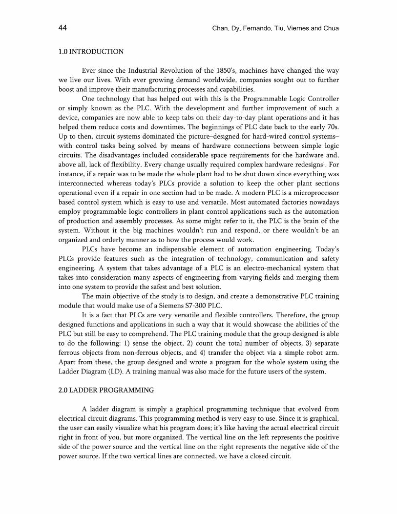
sagging. The angle bar (6mm) and the flat bar (4mm) is made of mild steel. To make sure that it would be rigid and strong, the frame is constructed from stainless steel. Furthermore, it was plated so that it would not be vulnerable to rust. Figure 3 shows the early stage in the fabrication of the conveyor still without the belt. Figure 4 shows the finished conveyor system that
Figure 3. Conveyor Frame with the Motor
now includes the sensors, relays, switches, and all the other components necessary to make it run. A safety mesh was also added to ensure the safety of the future users of the training module.3.2 Robot Arm
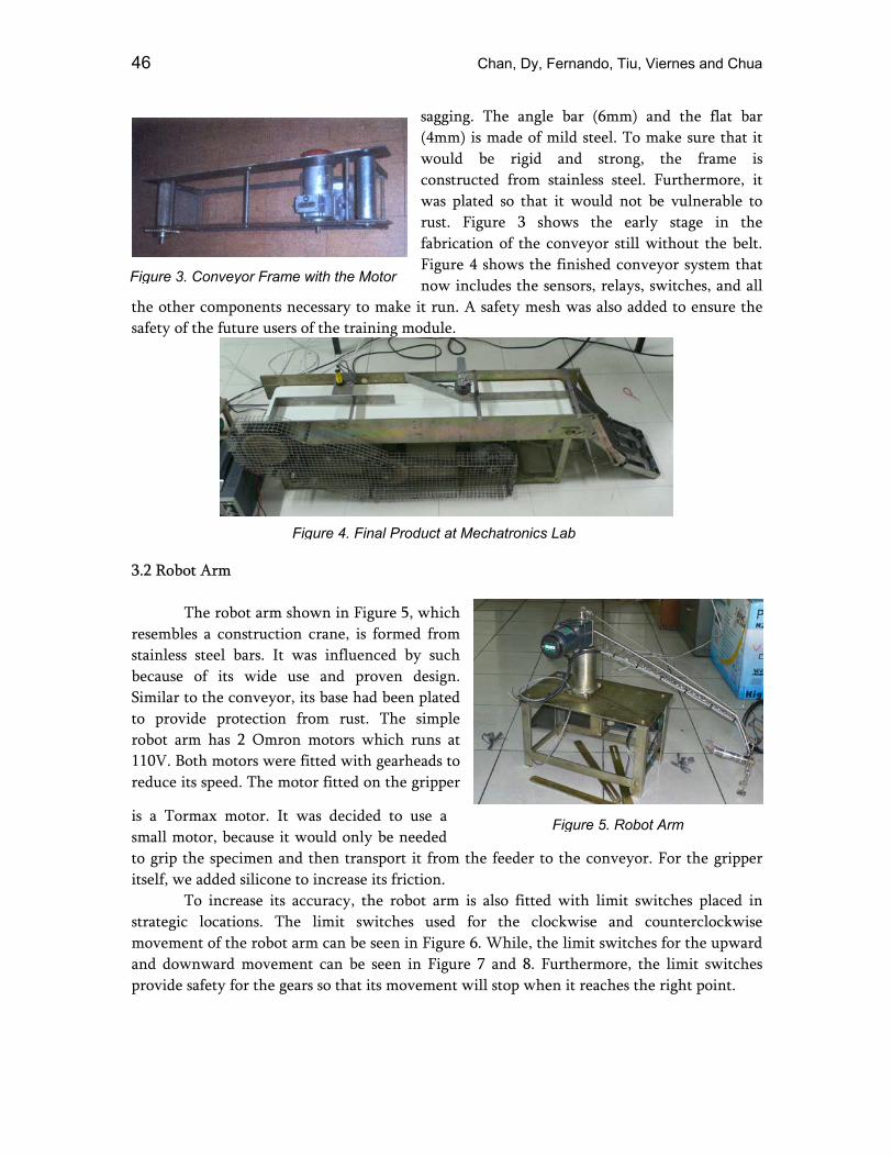
The robot arm
resembles a constructistainless steel bars. Itbecause of its wide Similar to the conveyoto provide protectionrobot arm has 2 Omr110V. Both motors wereduce its speed. The m
is a Tormax motor. Ismall motor, because ito grip the specimen aitself, we added silicon To increase itsstrategic locations. Tmovement of the roboand downward movemprovide safety for the g
Figure 4. Final Product at Mechatronics Lab
shown in Figure 5, which on crane, is formed from was influenced by such use and proven design. r, its base had been plated from rust. The simple on motors which runs at re fitted with gearheads to
otor fitted on the gripper
t was decided to use a t would only be needed nd then transport it from the feeder te to increase its friction.
accuracy, the robot arm is also fittedhe limit switches used for the clot arm can be seen in Figure 6. While, th
ent can be seen in Figure 7 and 8. Fears so that its movement will stop wh
Figure 5. Robot Arm
o the conveyor. For the gripper
with limit switches placed in ckwise and counterclockwise e limit switches for the upward urthermore, the limit switches
en it reaches the right point.
Programmable Logic Controller Training Module using Siemens S7-300 PLC 47
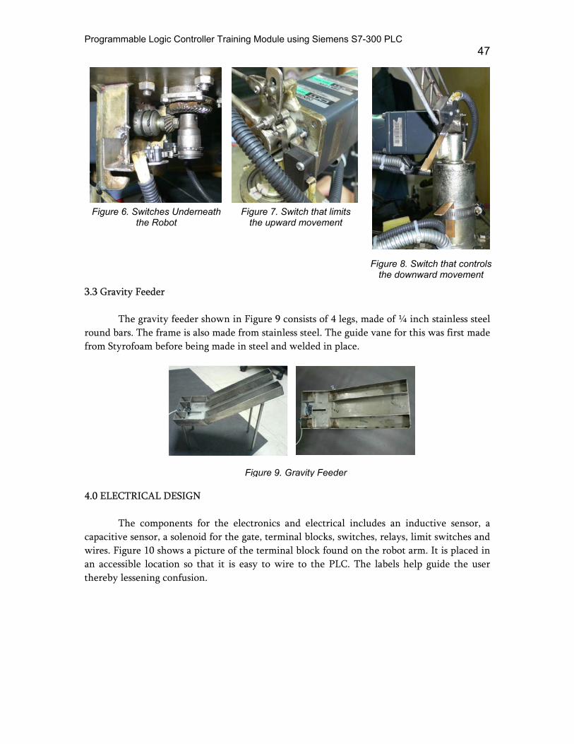
Figure 6. Switches Underneath
the Robot Figure 7. Switch that limits
the upward movement Figure 8. Switch that controls
the downward movement 3.3 Gravity Feeder
The gravity feeder shown in Figure 9 consists of 4 legs, made of ¼ inch stainless steel round bars. The frame is also made from stainless steel. The guide vane for this was first made from Styrofoam before being made in steel and welded in place.
Figure 9. Gravity Feeder 4.0 ELECTRICAL DESIGN The components for the electronics and electrical includes an inductive sensor, a capacitive sensor, a solenoid for the gate, terminal blocks, switches, relays, limit switches and wires. Figure 10 shows a picture of the terminal block found on the robot arm. It is placed in an accessible location so that it is easy to wire to the PLC. The labels help guide the user thereby lessening confusion.

48 Chan, Dy, Fernando, Tiu, Viernes and Chua
k l The control panel in Figure 11 is situated at t
circuit breaker, a selector switch, push buttons, and inddetermining the setting to be used. Figure 12 illustrates the wiring of the various di 5.0 SYSTEM PROCESS
The object to be transported is similar to Engineering Laboratory that is being used for the coursewide, and 15 mm thick. The group has provided dimensions made of mild steel and wood.
The whole process can be summed up in threstarting point), the conveyor, and the discharge bay. Th
The simple robot that the group designed will bsecond, which is the conveyor belt. The specimen wiblock will then be detected by a limit switch, whicsomething to be picked up. Once picked, the robot wclearance of about 10 mm.
The conveyor consists of an inductive sensor asensor, which senses any type of material, will cou
Figure 11. Conveyor Control Pane
Figure 10. Robot Arm Terminal Bloche side of the conveyor. It includes a icator lamps to help guide the user in
gital inputs to the PLC.
Figure 12. Digital Inputs to PLC
the one found in the Mechanical CNCMACH. It is 90mm long, 50 mm additional specimen with the same
e sections: the feeder section (or the is can be seen in Figure 13. e in between the first section and the ll be placed on a gravity feeder. The h would tell the robot that there is ill drop this at the conveyor with a
nd a capacitive sensor. The capacitive nt the number of specimen passing
Programmable Logic Controller Training Module using Siemens S7-300 PLC 49
through it. Beside the capacitive sensor, an inductive sensor will be placed, so that it will trigger an event when a ferrous object passes. If a logic “1” is seen, the solenoid will activate thus the gate will open up to separate the ferrous materials from the non-ferrous materials. However, if a logic “0” happens, then the gate will not open therefore the object will just head straight.
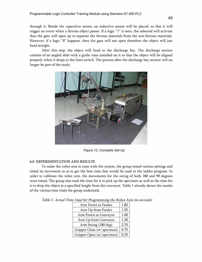
After this step, the object will head to the discharge bay. The discharge section consists of an angled slide with a guide vane installed on it so that the object will be aligned properly when it drops to the limit switch. The process after the discharge bay section will no longer be part of the study.
6.0 EXPERIMENTATION AND R
To make the robot arm in timed its movement so as to get torder to calibrate the robot arm, were timed. The group also took thit to drop the object at a specified hof the various time trials the group
Table 1. Actual Time Used
AA
ArAr
AGrippGripp
Figure 13. Complete Set-Up
ESULTS tune with the system, the group tested various settings and he best time that would be used in the ladder program. In the movements for the swing of both 180 and 90 degrees e time for it to pick up the specimen as well as the time for eight from the conveyor. Table 1 already shows the results
undertook.
for Programming the Robot Arm (in seconds) rm Down to Feeder 1.82rm Up from Feeder 1.92
m Down to Conveyor 1.00m Up from Conveyor 1.20rm Swing (180 deg) 2.70er Close (w/ specimen) 0.75er Open (w/ specimen) 0.25
50 Chan, Dy, Fernando, Tiu, Viernes and Chua
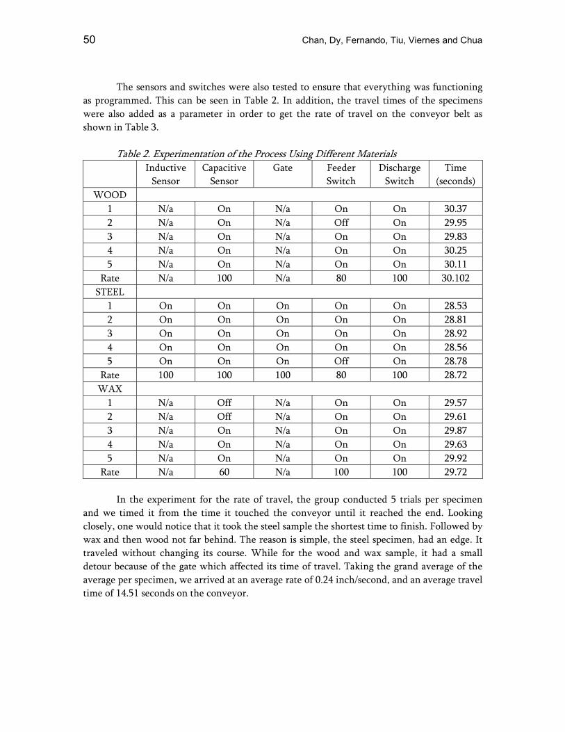
The sensors and switches were also tested to ensure that everything was functioning
as programmed. This can be seen in Table 2. In addition, the travel times of the specimens were also added as a parameter in order to get the rate of travel on the conveyor belt as shown in Table 3.
Table 2. Experimentation of the Process Using Different Materials
Inductive Sensor
Capacitive Sensor
Gate Feeder Switch
Discharge Switch
Time (seconds)
WOOD 1 N/a On N/a On On 30.37 2 N/a On N/a Off On 29.95 3 N/a On N/a On On 29.83 4 N/a On N/a On On 30.25 5 N/a On N/a On On 30.11
Rate N/a 100 N/a 80 100 30.102 STEEL
1 On On On On On 28.53 2 On On On On On 28.81 3 On On On On On 28.92 4 On On On On On 28.56 5 On On On Off On 28.78
Rate 100 100 100 80 100 28.72 WAX
1 N/a Off N/a On On 29.57 2 N/a Off N/a On On 29.61 3 N/a On N/a On On 29.87 4 N/a On N/a On On 29.63 5 N/a On N/a On On 29.92
Rate N/a 60 N/a 100 100 29.72
In the experiment for the rate of travel, the group conducted 5 trials per specimen and we timed it from the time it touched the conveyor until it reached the end. Looking closely, one would notice that it took the steel sample the shortest time to finish. Followed by wax and then wood not far behind. The reason is simple, the steel specimen, had an edge. It traveled without changing its course. While for the wood and wax sample, it had a small detour because of the gate which affected its time of travel. Taking the grand average of the average per specimen, we arrived at an average rate of 0.24 inch/second, and an average travel time of 14.51 seconds on the conveyor.

Programmable Logic Controller Training Module using Siemens S7-300 PLC 51
Table 3. Rate of Travel
Time (seconds) Rate = L/time (in./sec.) WAX
1 14.57 0.2402 2 14.61 0.2396 3 14.87 0.2354 4 14.63 0.2392 5 14.92 0.2346
Average 14.72 0.2378 WOOD
1 15.37 0.2277 2 14.95 0.2341 3 14.83 0.2360 4 15.25 0.2295 5 15.11 0.2316
Average 15.10 0.2318 STEEL
1 13.53 0.2587 2 13.81 0.2534 3 13.92 0.2514 4 13.56 0.2581 5 13.78 0.2540
Average 13.72 0.2551 Grand Average 14.51 0.2416 Note: L = 3.5 inches (90 mm)
Table 4. Positioning Using Limit Switches
Trials Swing to Feeder
Down toFeeder
Up fromFeeder
Swing to Conveyor
Down to Conveyor
Up from Conveyor
1 O O O O O O 2 O O O O X O 3 O O O O O O 4 O O O O O O 5 O X O O O O 6 O O O O O O 7 O X O O X O 8 O O O O O O 9 O X O O O O
10 O O O O O O 100% 70% 100% 100% 80% 100%

52 Chan, Dy, Fernando, Tiu, Viernes and Chua
The results from the positioning test in Table 4 were mostly positive with only a few errors. This means that the limit switches are reliable in controlling the movement of the robot arm. More importantly, we had the system and the training manual evaluated by students to get more input from outside the group and the results of this is shown in Table 5.
Table 5. Student Evaluation
Instruction: Rate the following statements with 5 being the highest grade possible. 5 4 3 2 1 1. The PLC Training Manual gave sufficient information about the module.
89% 11% 0% 0% 0%
2. The manual was presented in an organized manner.
61% 39% 0% 0% 0%
3. The ladder programming instructions were clear and easy to follow.
83% 17% 0% 0% 0%
4. The exercises with regards to their difficulty (5 being very hard).
11% 11% 56% 11% 11%
With the experimentation and the adjustments done, the group sought out to let the whole system be evaluated by undergraduate students taking up MECALAB. This was the final step that we took so that we could view the thesis from the eyes of other students. The choice of just getting senior students here was due to the complexity of the subject matter. In order to appreciate mechatronics, a student should have passed through the basic and advanced electrical and electronic subjects as well as the fundamental subjects of mechanical engineering so that the process of understanding the system would be easier. A total of 18 students took the demonstration.
As the evaluation form shows us, the group was able to provide a training manual in an organized and understandable manner. According to 56% of the correspondents, the exercises were challenging enough but it got quite hard in the final experiment.
Programmable Logic Controller Training Module using Siemens S7-300 PLC 53
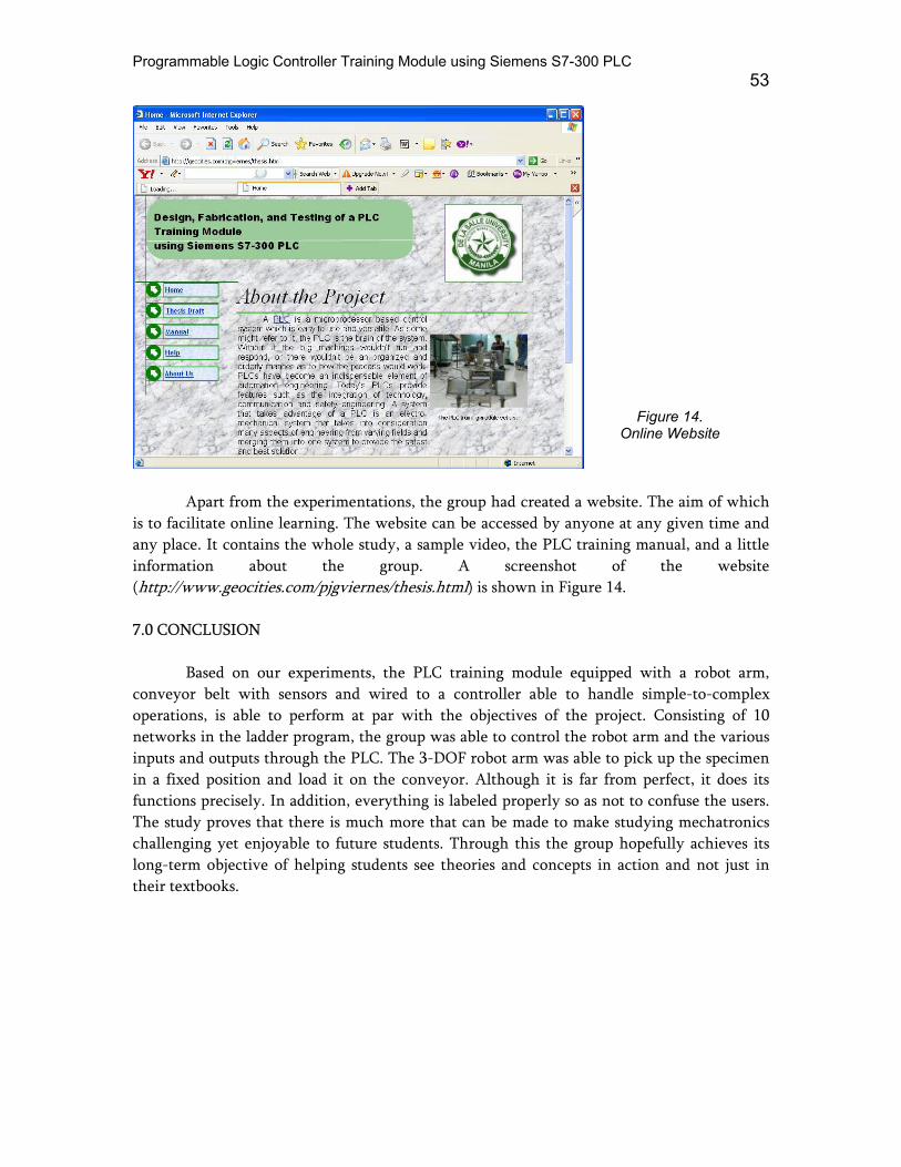
Figure 14. Online Website
Apart from the experimentations, the group had created a website. The aim of which is to facilitate online learning. The website can be accessed by anyone at any given time and any place. It contains the whole study, a sample video, the PLC training manual, and a little information about the group. A screenshot of the website (http://www.geocities.com/pjgviernes/thesis.html) is shown in Figure 14. 7.0 CONCLUSION
Based on our experiments, the PLC training module equipped with a robot arm, conveyor belt with sensors and wired to a controller able to handle simple-to-complex operations, is able to perform at par with the objectives of the project. Consisting of 10 networks in the ladder program, the group was able to control the robot arm and the various inputs and outputs through the PLC. The 3-DOF robot arm was able to pick up the specimen in a fixed position and load it on the conveyor. Although it is far from perfect, it does its functions precisely. In addition, everything is labeled properly so as not to confuse the users. The study proves that there is much more that can be made to make studying mechatronics challenging yet enjoyable to future students. Through this the group hopefully achieves its long-term objective of helping students see theories and concepts in action and not just in their textbooks.

54 Chan, Dy, Fernando, Tiu, Viernes and Chua
lt
r
REFERENCES Bunye E., D. Chan , P. Li, S. Maniquis and M.S. So (1996) PLC Based Multi-selection
Packaging System. Undergraduate thesis, De La Salle University. Bolton, W. (1995) Mechatronics: Electronic Control Systems in Mechanical Engineering.
Addison Wesley, England. Crispin, A. (1997) Programmable Logic Controllers and Their Engineering Applications (2nd
Edition.) McGraw-Hill Publishing Company, England. Fraser, C. and J. Milne, (1994) Integrated Electrical and Electronic Engineering for
Mechanica Engineers. McGraw-Hill Publishing Company, England. Siskind, C. (1982) Electrical Machines Direct and Alterna ing Current. McGraw-Hill
Kogakusha, Ltd. ABOUT THE AUTHORS
Humprey Levi T. Dy, Arvin H. Fernando, and Richmond L. Tiu earned their Bachelor of Science degrees in Mechanical Engineering from DLSU-Manila. They graduated in October 2006. Johanns C. Chan and Patrick John G. Viernes earned their Bachelor of Science degrees in Mechanical Engineering from DLSU-Manila. They graduated in January 2007.
Dr. Alvin Chua is an associate professor of the Mechanical Engineering Department, De La Salle University-Manila, Philippines. He earned his BSME, MSME, and Ph.D. in ME at De La Salle University-Manila. As a scholar under the Department of Science and Technology-Engineering and Science Education Project (DOST-ESEP), he conducted research at the University of New South Wales, Australia. He received a special citation fo the 2003 NAST-DuPont Talent Search for Young Scientists (Mechanical Engineering). He has published several papers in international conferences like Conference on Decision and Control (CDC), and Advance Intelligent Mechatronics (AIM). His research interests are on mechatronics, optimal estimation (Kalman Filters), instrumentation and controls, and robotics.