plc training notes - un.uobasrah.edu.iq
TRANSCRIPT

PLC Training Notes
Why control system is required?
- Control sequence of events,
- Keep variables constant,
- Follow some prescribed changes,
- and many more.
Example 1: Automatic drilling machine
Example 2: Deflection-type packaging system
Example 3: Mixing process

Note that the basic control circuit for the motors in the above examples is:
What is PLC?
Programmable Logic Controller is a special form of microprocessor-based controller that uses
‘programmable memory’ that stores instructions and to implement functions such as logic,
sequencing, timing, counting, and arithmetic in order to control machines and processes. First PLC
was developed in 1969.
Why the term ‘Logic’ was used?
Because programming is primarily concerned with implementing logic and switching operations.
Example:

If switch A closes → output to motor circuit
If switch B closes → output to valve circuit
PLCs are optimized for control tasks and the industrial environment:
- Designed to withstand vibrations, temperatures, humidity, and noise.
- Interfacing for inputs and outputs already inside the PLC.
- Easy to program (logic & switching).
PLC Hardware
- CPU
- Power supply (e.g. 5V)
- Programming device
- Memory unit
- Inputs and outputs (digital/discreate/analog)
- Communications interface (remote plc networks)
- Typical clock speed 1-8MHz

Since the CPU operates typically on 5V, we need:
Optoisolators (optocouplers) for inputs/output channels to enable wide range of voltages to be
treated and to isolate the plc internal circuitry.

Signal conditioning with relays, transistors, or triacs, the plc output channels might be:
- Relays: (1) slow to operate (2) suitable for AC/DC switching
- Transistors: (1) Fast switching (2) DC loads only (3) Destroyed easily by over current
- Triacs: (1) Fast switching (2) AC loads only (3) Destroyed easily by over current
- Fuses might be included to protect such outputs inside the plc.
Sourcing and Sinking
It is important to know the type of input or output connected so that it can be correctly connected
to the plc.

Test:
PLC Systems
Single box (brick) Modular system
6, 8, 12, or 24 inputs 4, 8. 16 outputs
Extendable to cope too many inputs/outputs 10, 20, 30, 40, or 100 etc
300-1000 instructions can be stored in memory Extendable memory
Ex: MELSEC FX3U Ex: OMRON CPM1A

MELSEC FX3U
OMRON CPM1A

PLC Programming Languages
The International Electrotechnical Commision IEC-61131-3 defines five programming languages to
program the PLC in 1993.
- Ladder Diagram (LAD)
- Sequential Function Chart (SFC)
- Functional Block Diagram (FBD)
- Structed Text (ST)
- Instruction List (IL)
Programming Tools:
- Handheld programming device
- Desktop consoles
- Personal computers
Programming software:
- Mitsubishi (GX-Developer)
- Siemens (SIMATIC STEP 7)
- Rockwell Automation (RSLogix)
- OMRON (CX-One)
- Telemecanique (ProWorx)

PLC Ladder programming
Writing codes in assembly languages or high-level languages like FORTRAN, C, COBOL requires some
skill in programming.
Plcs were intended to be used by engineers without any great knowledge of programming.
→ Ladder programming
Vertical lines → power line or power rail
Horizontal lines → control portion of the circuit (rung)
- Power flow from left to right
- Each rung defines one operation in the control process
- Ladder program should be read from left to right and from top to bottom
- The procedure of going through all rungs of the program by the PLC in the run mode is called
‘cycle’
- ‘scan time’ depends on the number of rungs and it is typically 1ms/1000 byte.
- Each rung must start with inputs and end with at least one output.
- The outputs are not updated but the results stored in memory and all the outputs are
updated simultaneously at the end of the cycle.
- A particular device can appear in more than one rung of a ladder. The same letters and/or
numbers should be used in each situation.
- I/O addresses are all identified by the PLC manufacturer.

Implementing AND Gate
On a ladder diagram, contacts in the horizontal rung or in series, represent the logical AND
operation.
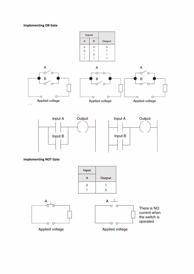
Implementing OR Gate
Implementing NOT Gate

Test: Implement NAND, NOR, and XOR gates
Latching circuit
There are often situations in which it is necessary to hold an output energized, even when the input
ceases. A simple example of such a situation is a motor that is started by pressing a push-button
witch. Though the switch contacts do not remain closed, the motor is required to continue running
until a stop push-button switch is pressed. The term latch circuit is used for the circuit that carries
out such an operation. It is a self-maintaining circuit in that, after being energized, it maintains that
state until another input is received.
Latching circuit
Example: Latching circuit with ON/OFF lamps

Multiple outputs
Sequenced outputs
Test:

Internal Relays
In PLCs there are elements that are used to hold data, that is, bits, and behave like relays, being able
to be switched on or off and to switch other devices on or off. Hence the term internal relay.
→ also called Auxiliary relays, markers, flags, coils, and bits.
Mitsubishi uses the notation M100, M101, etc as addresses for these relays.

Example: It is required to activate a system where two different set of lamps are realized.
In2 → main system switch
In1 & In3 → photo cells
In4 → limit switch
Test: latching problem
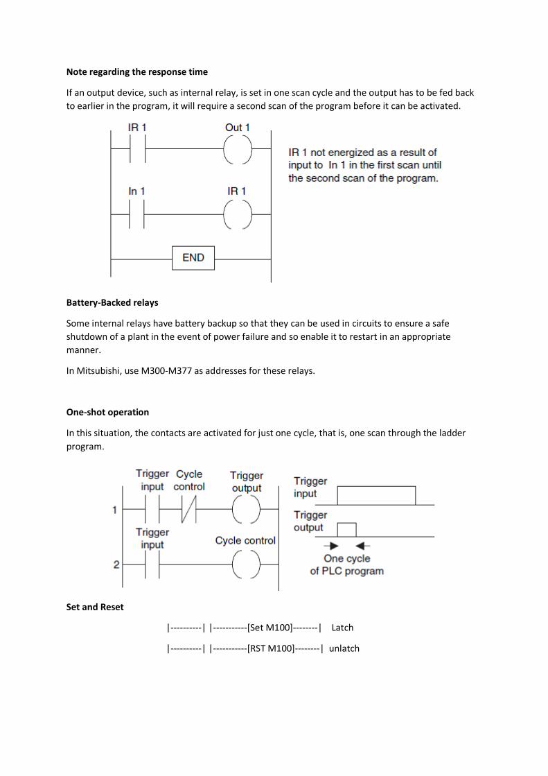
Note regarding the response time
If an output device, such as internal relay, is set in one scan cycle and the output has to be fed back
to earlier in the program, it will require a second scan of the program before it can be activated.
Battery-Backed relays
Some internal relays have battery backup so that they can be used in circuits to ensure a safe
shutdown of a plant in the event of power failure and so enable it to restart in an appropriate
manner.
In Mitsubishi, use M300-M377 as addresses for these relays.
One-shot operation
In this situation, the contacts are activated for just one cycle, that is, one scan through the ladder
program.
Set and Reset
|----------| |-----------[Set M100]--------| Latch
|----------| |-----------[RST M100]--------| unlatch

Test : Fire alarm system
Test: Moving workpiece cutter
Master Control Relays
MC N M
MCR N
N is the node number
M is the internal relay used

Jump and Call
CJ P
P is the pointer or label to be jumped to
If x0 energized, then the program will jump to P10 location and start to run the instructions
afterwards.
Subroutines
Small programs to perform specific tasks that can be called for use in larger programs.

Timers
PLCs thus have timers as built-in devices. Timers count seconds or fractions of seconds using the internal CPU clock.
K is the time-based multiplier e.g. 100 ms
Test: Design a fire alarm system using MQ-series gas sensors. Avoid the first 5 seconds fault alarm
using timers.

Example: Use timers to switch on three motors in a sequence
Cascading timers
Since K is ranged between 1 up to 999. What if you want 120 sec delay?
➔ Cascading

Example: Use timers to generate 5 seconds On/Off waveform
Off-delay timer
Pulsed output

Example: Design a flashing light program where there is an output
Test:

Counters
Counters are provided as built-in elements in PLCs and allow the number of occurrences of input signals to be counted.
Example : Machine is required to direct 6 tins along one path for packaging in a box and then 12 tins
along another path for packaging in another box.
Example: Car parking system