design and vibration mode analysis of crank shaft for four ...€¦ · the reciprocating motion...
TRANSCRIPT
50
Design and Vibration Mode Analysis of Crank Shaft for Four Stroke Single Cylinder Petrol Engine
Ambati Babi Reddy1 and Reddy Sreenivasulu2
Department of Mechanical Engineering, R.V.R & J.C. College of Engineering, Guntur 522019, Andhra Pradesh, India. [email protected], [email protected]
Abstract--The crankshaft is the part of an engine which trans-lates reciprocating linear piston motion into rotation. To convert the reciprocating motion into rotation, the crankshaft has crank-pins, additional bearing surfaces whose axis is offset from that of the crank, to which the “big ends” of the connecting rod from each cylinder attach. It typically connects to a flywheel, to reduce the pulsation characteristic of the four stroke cycle, and some-times a torsional or vibrational damper at the opposite end, to reduce the torsion vibrations often caused along the length of the crankshaft by the cylinders farthest from the output end acting on the torsion elasticity of the metal. In this paper, the modelling of the crankshaft is created using CATIA-V5 software. Finite element analysis (FEA) is performed to obtain the variation of stress at critical locations of the crank shaft using the ANSYS software and applying the boundary conditions. Further it can be extended for the different materials. Then the results are drawn von-misses stress induced in the crankshaft is 18.178Mpa and shear stress is induced in the crankshaft is 9.5995Mpa. The Theoretical results are obtained von-misses stress is 19.6Mpa, shear stress is 9.28Mpa. The validation of model is compared with the Theoretical and FEA results of von-misses stress and shear stress are within the limits. Along with static analysis of crank shaft, further vibration mode analysis has to be done to identify pulsation characteristics of the crankshaft throughout its length for different materials.
Keywords: Crankshaft, Static analysis, Von-misses stress, Vibration mode analysis.
positions. Crankshafts find many applications in various branches of engineering. They are used whenever there is the need to translate reciprocating linear motion into rotation or vice-versa. In their more varied configurations, crankshafts are usually used in internal combustion engines but also in piston steam engines. It lays on the former the vaster and varied range of applications of crankshafts.
A crankshaft model is created by CATIA-V5 software and then imported to ANSYS software. Based on the stress analysis, calculation of fatigue strength of the crankshaft will be able to achieve the design requirements. This paper also deals with the dynamic analysis of the whole crankshaft. Results from the FE model are then presented which includes identification of the critically stressed location, variation of stresses over an entire cycle, and a discussion of the effects of engine speed as well as torsion load on stresses. The other objective of this analysis was to judge the suitability of forged steel crankshaft, which not only reduces the final production cost of the component, but also results in an efficient performance engine. Next objective is to perform static load and stress analysis
II. LITERATURE REVIEWSolanki et al. [1] presented literature review on crankshaft design and optimization. The materials, manufacturing process, failure analysis, design consideration etc were reviewed. The design of the crankshaft considers the dynamic loading and the optimization can lead to a shaft diameter satisfying the requirements of the automobile specifications with cost and size effectiveness. They concluded that crack grows faster on the free surface while the central part of the crack front becomes straighter.
Montazersadgh and Fatemi [2] chose forged steel and a cast iron crankshaft of a single cylinder four stroke engine. Both crankshafts were digitized using a CMM machine. Load analysis was performed and verification of results by ADAMS modeling of the engine. At the next step, geometry and manufacturing cost optimization was performed. Considering torsional load in the overall dynamic loading conditions has no effect on von mises stress at the critically stressed location. Experimental stress and FEA results showed close agreement, within 7% difference. Critical locations on the crankshaft are
I. INTRODUCTIONCRANK SHAFT is a large component with a complex geometry in the I.C engine, which converts the reciprocating displacement of the piston to a rotary motion with a four bar link mechanism. Crankshaft experiences large forces from gas combustion. This force is applied to the top of the piston and since the connecting rod connects the piston to the crank shaft, the force will be transmitted to the crankshaft. The magnitude of the forces depends on many factors which consist of crank radius, connecting rod dimensions, and weight of the connecting rod, piston, piston rings, and pin. Crankshaft must be strong enough to take the downward force of the power stroke without excessive bending so the reliability and life of the internal combustion engine depend on the strength of the crankshaft largely. The crank pin is like a built in beam with a distributed load along its length that varies with crank
51
DESIGN AND ANALYSIS OF CRANK SHAFT
all located on the fillet areas because of high stress gradients in these locations.
Gongzhi et al. [3] carried out dynamic strength analysis of crankshaft for marine diesel engine. The finite element models of crankshaft, bearing, piston and connecting rod was created in ANSYS and simplified by sub structure technique. The result files of reduced models were introduced into EXCITE software to create multi-body dynamics calculation of crankshaft in one working cycle. Compared with single crankshaft strength analysis, non linear multi-body dynamics method is closer to the actual boundary conditions of the crankshaft load.
Yingkui and Zhibo [4] established three dimensional model of a diesel engine crankshaft by using Pro E software. Using ANSYS analysis tool, the finite element analysis for the crankshaft was conducted under extreme operation conditions and stress distribution of the crankshaft was presented. The crank stress change model and the crank stress biggest hazard point were found by using finite element analysis, and the improvement method for the crankshaft structure design was given.
Balamurugan et al. [5] done computer aided modeling and optimization analysis of crankshaft to evaluate and compare the fatigue performance. They compared two crankshafts, cast iron and forged steel, from a single cylinder four stroke engines. Finite element analysis was performed to obtain the variation of stress magnitude at critical locations. The dynamic analysis was done analytically and was verified by simulation in ANSYS.
Jian et al. [6] analyzed three dimensional model of 380 diesel engine crankshaft. They used ProE and ANSYS as FEA tools. First of all, the 380 diesel engine entity crankshaft model was created by Pro E software. Next, the model was imported to ANSYS software. Material properties, constraints boundary conditions and mechanical boundary conditions of the 380 diesel engine crankshaft were determined.
Bin et al. [7] investigated the vibration model of 480 diesel crankshaft and the stress analysis of crankpin. Three dimensional models of diesel engine crankshaft and crankpin were created through Pro E software. Finite element analysis software ANSYS was used to analyze the vibration model and the distortion and the stress status of the crankpin. This explains the relationship between the frequency and the vibration model.
Ling et al. [8] conducted fatigue life prediction modeling and residue life assessment based on statistics of historical working state (SHWS) at crankshaft using fatigue damage accumulation (FDA) theory. Dynamic response of typical operation performance is analyzed with software ANSYS of finite element analysis, and high stress zone was found.
Garg and Baghl [9] analyzed crankshaft model and crank throw were created by Pro/E Software and then imported to ANSYS software. The result shows that the improvement in the strength of the crankshaft as the maximum limits of stress, total deformation, and the strain is reduced. The weight of the crankshaft is reduced .There by, reduces the inertia force. As the weight of the crankshaft is decreased this will decrease the cost of the crankshaft and increase the I.C engine performance.
Choubey and Brahmbhatt [10] analyzed crankshaft model and 3-dimentional model of the crankshaft were created by SOLID WORKS Software and imported to ANSYS software. The crankshaft maximum deformation appears at the centre of crankpin neck surface. The maximum stress appears at the fillets between the crankshaft journals and crank cheeks and near the central point journal. The edge of main journal is high stress area.
Deshbhratar and Suple.[11] analyzed 4-cylinder crankshaft and models of the crankshaft were created by Pro/E Software and then imported to ANSYS software. The maximum deformation appears at the centre of crankshaft surface. The maximum stress appears at the fillets between the crankshaft journal and crank cheeks, and near the central point. The edge of main journal is high stress area.
S.J. Patil et al. [12] described the analytical and FE modal analysis of a crankshaft. The 3-dimentional model was constructed in pro/E and the analysis has to be done in ansys. Crankshaft considered as two rotor system to calculate the six modes of frequency. The results show that the crank shaft is not running in critical speed.
Murthy et al. [13] analyzed the Modeling, analysis and optimization of crankshaft. The analysis is done on two different materials are Annealed 4340 steel, Inconel x750 alloy. The models were created in catia-v5 and the analysis is to be done in ansys. The results are in strength point of view Inconel x750 is better than Annealed 4340 steel for crankshaft.
Chien et al. [14] investigated the stress concentration near the fillet of the crankshaft section under bending without consideration of residual stresses by a two dimensional elastic finite element analysis. The plastic zone development and the residual stress distribution near the crankshaft fillet induced by the fillet rolling process were then investigated by a two-dimensional elastic-plastic finite element analysis.
Based on the literature survey performed, venture into this work was amply motivated by the fact that a little work has been conducted to obtain Most of the works are done on static analysis, dynamic analysis, model analysis independently also with single material only. But in this work it is interpreted both design analysis and model analysis, due to this, the function of crank shaft satisfy fully.
52
AKGEC INTERNATIONAL JOURNAL OF TECHNOLOGY, Vol. 6, No. 2
II. MODELING AND ANALYSISConfiguration of the engine to which the crankshaft belongs:Crankshaft radius: 37 mmPiston diameter: 89 mmMass of the connecting rod: 0.283 kgMass of the piston assembly: 0.417 kgConnecting rod length: 120.78 mmIzz of connecting rod about the center of gravity: 0.663×10⁻³ kg-m2Distance of C.G. of connecting rod from crank end center: 28.6 mmMaximum gas pressure: 3.5 MPa
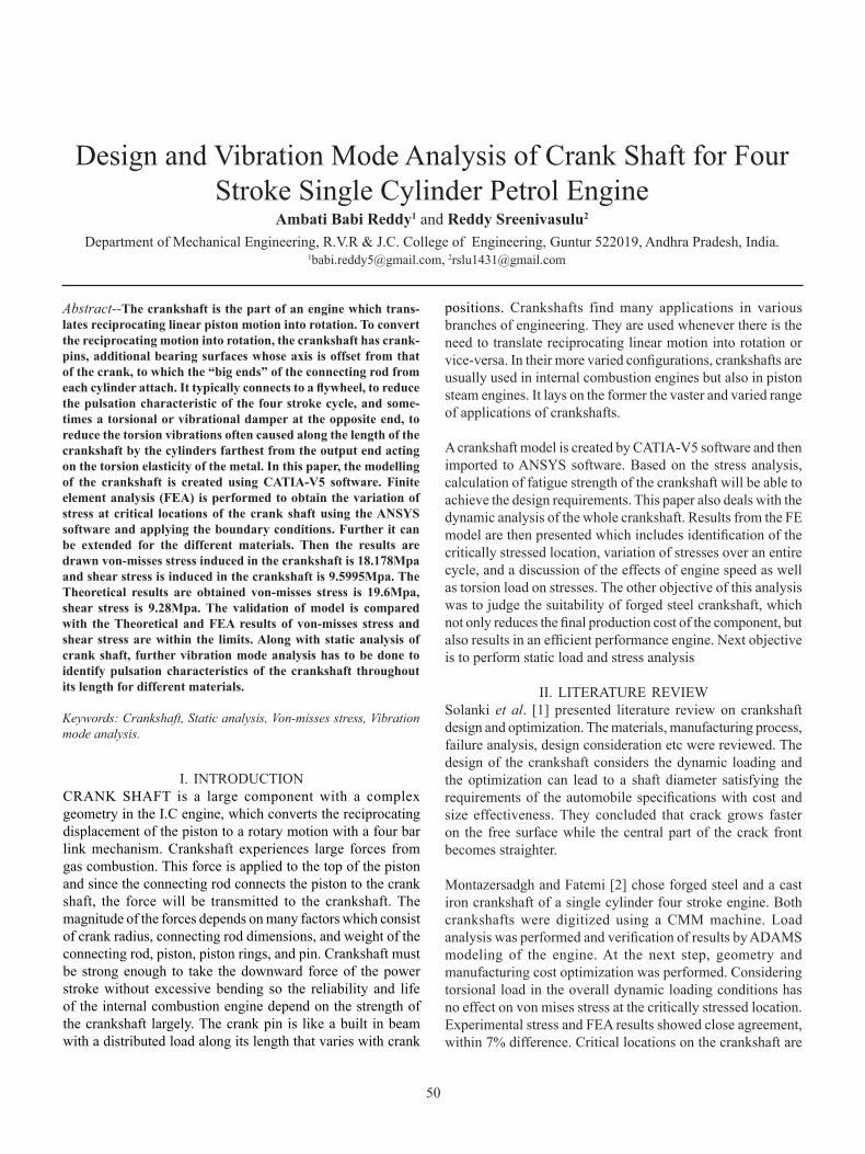
Figure 1. Crankshaft geometry and force directions bending (blue) (Fx), torsional (red) (Fy) and Longitudinal (green) (Fz).
There are two different load sources acting on the crankshaft. Inertia of rotating components (e.g. connecting rod) applies forces to the crankshaft and this force increases with the increase of engine speed. This force is directly related to the rotating speed and acceleration of rotating components. The second load source is the force applied to the crankshaft due to gas combustion in the cylinder. The slider-crank mechanism transports the pressure applied to the upper part of the slider to the joint between crankshaft and connecting rod. This transmitted load depends on the dimensions of the mechanism.
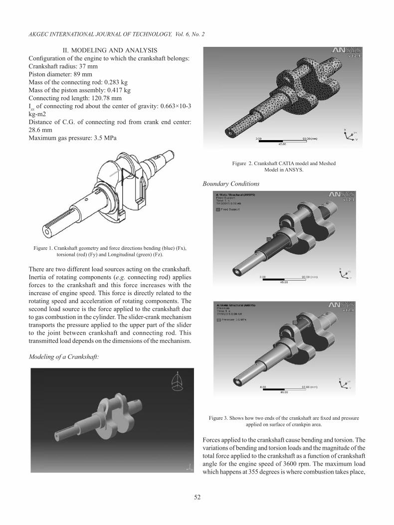
Modeling of a Crankshaft:
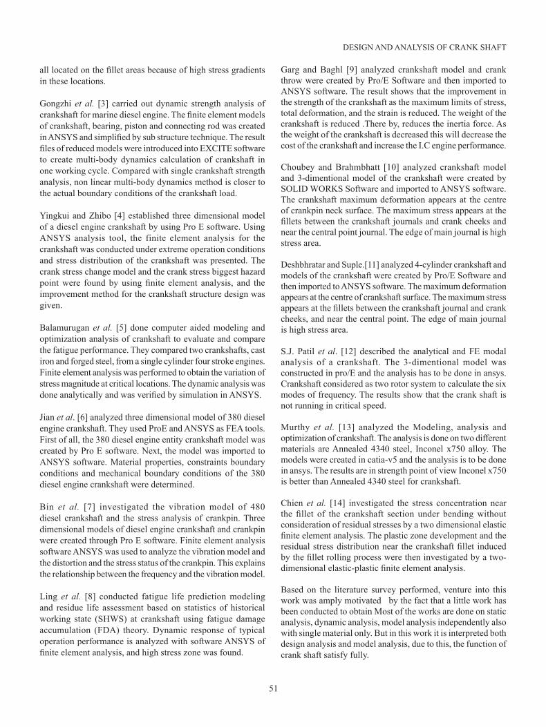
Figure 2. Crankshaft CATIA model and Meshed Model in ANSYS.
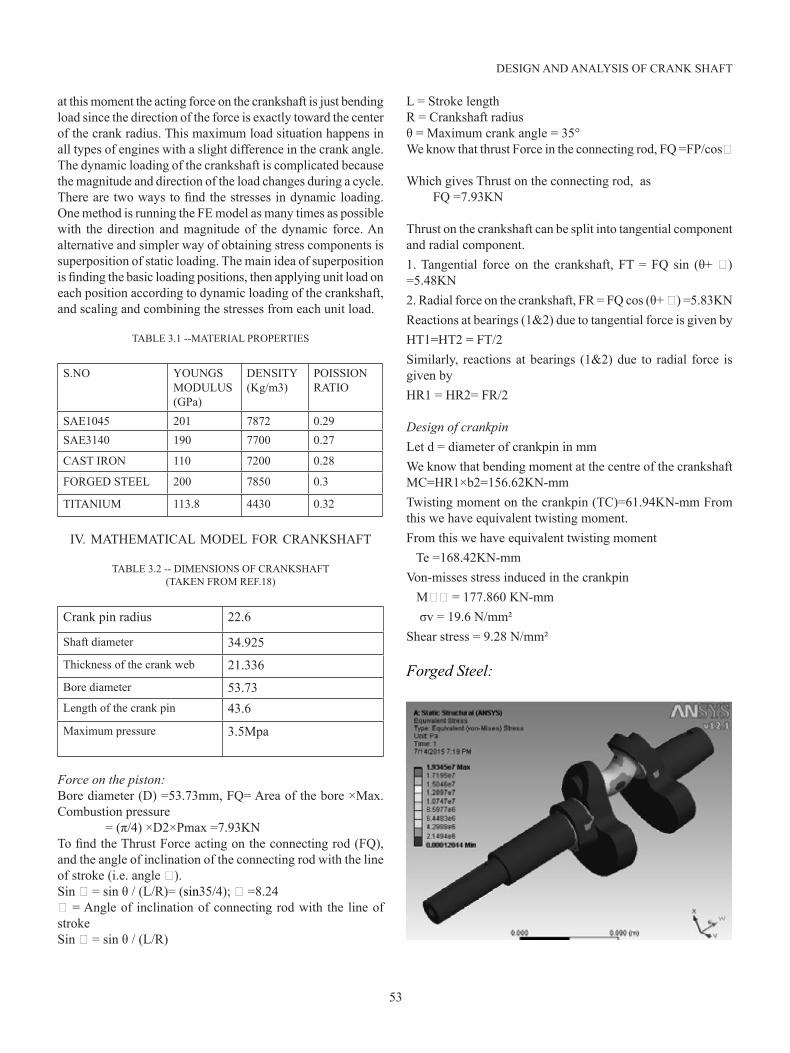
Boundary Conditions
Figure 3. Shows how two ends of the crankshaft are fixed and pressure applied on surface of crankpin area.
Forces applied to the crankshaft cause bending and torsion. The variations of bending and torsion loads and the magnitude of the total force applied to the crankshaft as a function of crankshaft angle for the engine speed of 3600 rpm. The maximum load which happens at 355 degrees is where combustion takes place,
53
DESIGN AND ANALYSIS OF CRANK SHAFT
at this moment the acting force on the crankshaft is just bending load since the direction of the force is exactly toward the center of the crank radius. This maximum load situation happens in all types of engines with a slight difference in the crank angle. The dynamic loading of the crankshaft is complicated because the magnitude and direction of the load changes during a cycle. There are two ways to find the stresses in dynamic loading. One method is running the FE model as many times as possible with the direction and magnitude of the dynamic force. An alternative and simpler way of obtaining stress components is superposition of static loading. The main idea of superposition is finding the basic loading positions, then applying unit load on each position according to dynamic loading of the crankshaft, and scaling and combining the stresses from each unit load.
TABLE 3.1 --MATERIAL PROPERTIES
S.NO YOUNGS MODULUS(GPa)
DENSITY(Kg/m3)
POISSION RATIO
SAE1045 201 7872 0.29SAE3140 190 7700 0.27
CAST IRON 110 7200 0.28
FORGED STEEL 200 7850 0.3
TITANIUM 113.8 4430 0.32
IV. MATHEMATICAL MODEL FOR CRANKSHAFT
TABLE 3.2 -- DIMENSIONS OF CRANKSHAFT (TAKEN FROM REF.18)
Crank pin radius 22.6
Shaft diameter 34.925Thickness of the crank web 21.336Bore diameter 53.73Length of the crank pin 43.6
Maximum pressure 3.5Mpa
Force on the piston: Bore diameter (D) =53.73mm, FQ= Area of the bore ×Max. Combustion pressure = (π/4) ×D2×Pmax =7.93KNTo find the Thrust Force acting on the connecting rod (FQ), and the angle of inclination of the connecting rod with the line of stroke (i.e. angle ϕ).Sin ϕ = sin θ / (L/R)= (sin35/4); ϕ =8.24ϕ = Angle of inclination of connecting rod with the line of strokeSin ϕ = sin θ / (L/R)
L = Stroke length R = Crankshaft radius θ = Maximum crank angle = 35°We know that thrust Force in the connecting rod, FQ =FP/cosϕ
Which gives Thrust on the connecting rod, as FQ =7.93KN
Thrust on the crankshaft can be split into tangential component and radial component.1. Tangential force on the crankshaft, FT = FQ sin (θ+ ϕ) =5.48KN 2. Radial force on the crankshaft, FR = FQ cos (θ+ ϕ) =5.83KN Reactions at bearings (1&2) due to tangential force is given byHT1=HT2 = FT/2Similarly, reactions at bearings (1&2) due to radial force is given by HR1 = HR2= FR/2
Design of crankpinLet d = diameter of crankpin in mm We know that bending moment at the centre of the crankshaft MC=HR1×b2=156.62KN-mm Twisting moment on the crankpin (TC)=61.94KN-mm From this we have equivalent twisting moment.From this we have equivalent twisting moment Te =168.42KN-mmVon-misses stress induced in the crankpin Mϕϕ = 177.860 KN-mm σv = 19.6 N/mm²Shear stress = 9.28 N/mm²
Forged Steel:
54
AKGEC INTERNATIONAL JOURNAL OF TECHNOLOGY, Vol. 6, No. 2
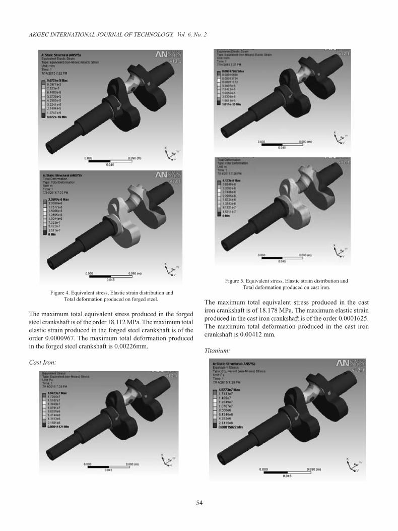
Figure 4. Equivalent stress, Elastic strain distribution and Total deformation produced on forged steel.
The maximum total equivalent stress produced in the forged steel crankshaft is of the order 18.112 MPa. The maximum total elastic strain produced in the forged steel crankshaft is of the order 0.0000967. The maximum total deformation produced in the forged steel crankshaft is 0.00226mm.
Cast Iron:
Figure 5. Equivalent stress, Elastic strain distribution and Total deformation produced on cast iron.
The maximum total equivalent stress produced in the cast iron crankshaft is of 18.178 MPa. The maximum elastic strain produced in the cast iron crankshaft is of the order 0.0001625. The maximum total deformation produced in the cast iron crankshaft is 0.00412 mm.
Titanium:
55
DESIGN AND ANALYSIS OF CRANK SHAFT
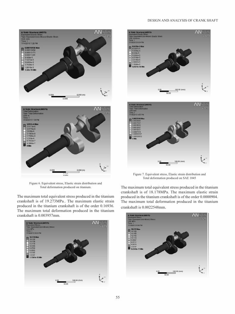
Figure 6. Equivalent stress, Elastic strain distribution and Total deformation produced on titanium.
The maximum total equivalent stress produced in the titanium crankshaft is of 19.273MPa.. The maximum elastic strain produced in the titanium crankshaft is of the order 0.16936. The maximum total deformation produced in the titanium crankshaft is 0.003957mm.
Figure 7. Equivalent stress, Elastic strain distribution and Total deformation produced on SAE 1045
The maximum total equivalent stress produced in the titanium crankshaft is of 18.178MPa. The maximum elastic strain produced in the titanium crankshaft is of the order 0.0000904. The maximum total deformation produced in the titanium crankshaft is 0.0022548mm.
56
AKGEC INTERNATIONAL JOURNAL OF TECHNOLOGY, Vol. 6, No. 2
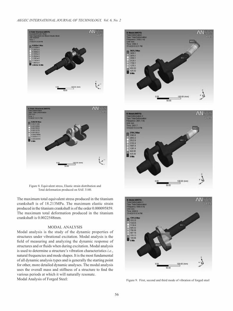
Figure 8. Equivalent stress, Elastic strain distribution and Total deformation produced on SAE 3140.
The maximum total equivalent stress produced in the titanium crankshaft is of 18.213MPa. The maximum elastic strain produced in the titanium crankshaft is of the order 0.000095859.The maximum total deformation produced in the titanium crankshaft is 0.0022548mm.
MODAL ANALYSISModal analysis is the study of the dynamic properties of structures under vibrational excitation. Modal analysis is the field of measuring and analyzing the dynamic response of structures and or fluids when during excitation. Modal analysis is used to determine a structure’s vibration characteristics i.e., natural frequencies and mode shapes. It is the most fundamental of all dynamic analysis types and is generally the starting point for other, more detailed dynamic analyses. The modal analysis uses the overall mass and stiffness of a structure to find the various periods at which it will naturally resonate. Modal Analysis of Forged Steel: Figure 9. First, second and third mode of vibration of forged steel
57
DESIGN AND ANALYSIS OF CRANK SHAFT
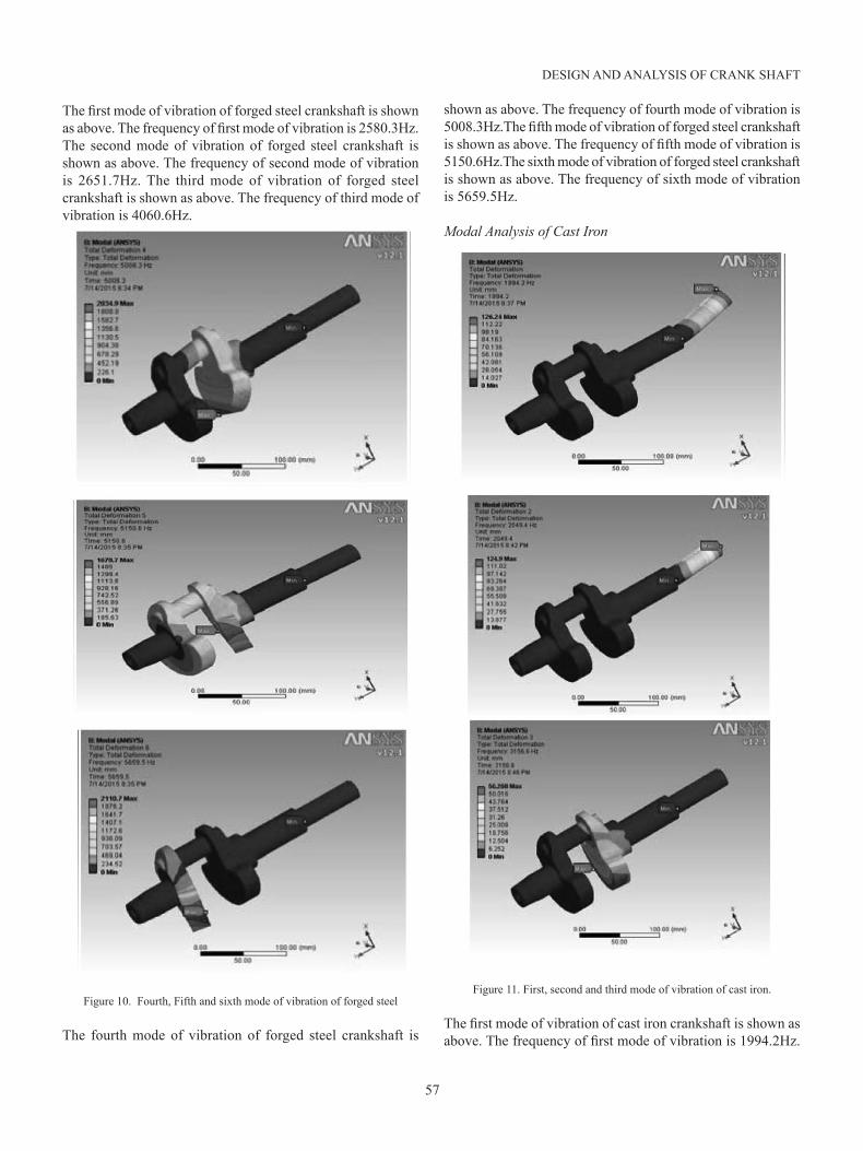
The first mode of vibration of forged steel crankshaft is shown as above. The frequency of first mode of vibration is 2580.3Hz.The second mode of vibration of forged steel crankshaft is shown as above. The frequency of second mode of vibration is 2651.7Hz. The third mode of vibration of forged steel crankshaft is shown as above. The frequency of third mode of vibration is 4060.6Hz.
Figure 10. Fourth, Fifth and sixth mode of vibration of forged steel
The fourth mode of vibration of forged steel crankshaft is
shown as above. The frequency of fourth mode of vibration is 5008.3Hz.The fifth mode of vibration of forged steel crankshaft is shown as above. The frequency of fifth mode of vibration is 5150.6Hz.The sixth mode of vibration of forged steel crankshaft is shown as above. The frequency of sixth mode of vibration is 5659.5Hz.
Modal Analysis of Cast Iron
Figure 11. First, second and third mode of vibration of cast iron.
The first mode of vibration of cast iron crankshaft is shown as above. The frequency of first mode of vibration is 1994.2Hz.
58
AKGEC INTERNATIONAL JOURNAL OF TECHNOLOGY, Vol. 6, No. 2
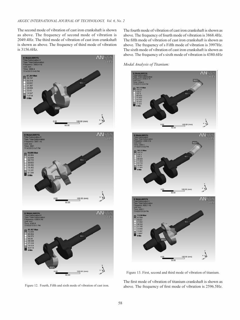
The second mode of vibration of cast iron crankshaft is shown as above. The frequency of second mode of vibration is 2049.4Hz. The third mode of vibration of cast iron crankshaft is shown as above. The frequency of third mode of vibration is 3156.6Hz.
Figure 12. Fourth, Fifth and sixth mode of vibration of cast iron.
The fourth mode of vibration of cast iron crankshaft is shown as above. The frequency of fourth mode of vibration is 3868.4Hz.The fifth mode of vibration of cast iron crankshaft is shown as above. The frequency of s Fifth mode of vibration is 3997Hz.The sixth mode of vibration of cast iron crankshaft is shown as above. The frequency of s sixth mode of vibration is 4380.6Hz
Modal Analysis of Titanium:
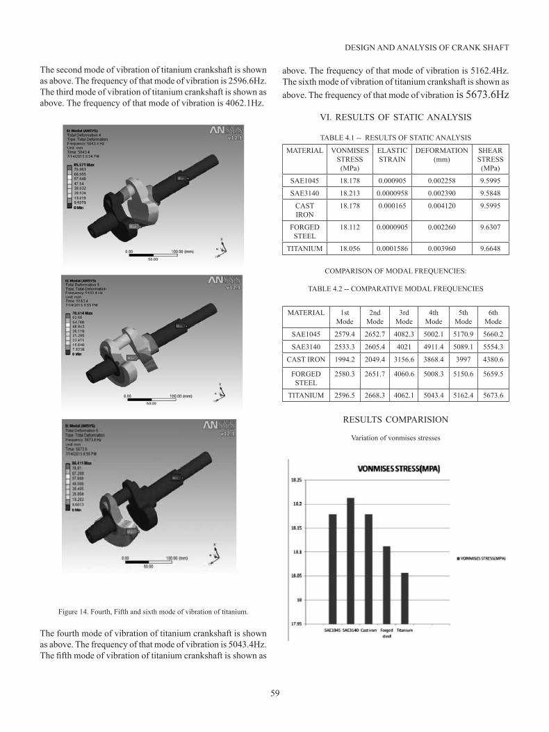
Figure 13. First, second and third mode of vibration of titanium.
The first mode of vibration of titanium crankshaft is shown as above. The frequency of first mode of vibration is 2596.5Hz.
59
DESIGN AND ANALYSIS OF CRANK SHAFT
The second mode of vibration of titanium crankshaft is shown as above. The frequency of that mode of vibration is 2596.6Hz. The third mode of vibration of titanium crankshaft is shown as above. The frequency of that mode of vibration is 4062.1Hz.
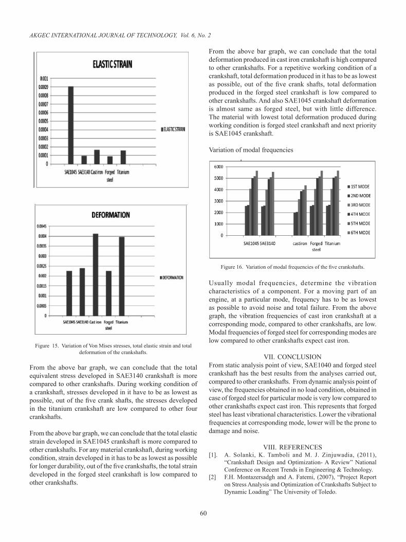
Figure 14. Fourth, Fifth and sixth mode of vibration of titanium.
The fourth mode of vibration of titanium crankshaft is shown as above. The frequency of that mode of vibration is 5043.4Hz. The fifth mode of vibration of titanium crankshaft is shown as
above. The frequency of that mode of vibration is 5162.4Hz.The sixth mode of vibration of titanium crankshaft is shown as above. The frequency of that mode of vibration is 5673.6Hz
VI. RESULTS OF STATIC ANALYSIS
TABLE 4.1 -- RESULTS OF STATIC ANALYSIS
MATERIAL VONMISES STRESS
(MPa)
ELASTIC STRAIN
DEFORMATION(mm)
SHEAR STRESS
(MPa)
SAE1045 18.178 0.000905 0.002258 9.5995
SAE3140 18.213 0.0000958 0.002390 9.5848
CAST IRON
18.178 0.000165 0.004120 9.5995
FORGED STEEL
18.112 0.0000905 0.002260 9.6307
TITANIUM 18.056 0.0001586 0.003960 9.6648
COMPARISON OF MODAL FREQUENCIES:
TABLE 4.2 -- COMPARATIVE MODAL FREQUENCIES
MATERIAL 1st Mode
2nd Mode
3rd Mode
4th Mode
5th Mode
6th Mode
SAE1045 2579.4 2652.7 4082.3 5002.1 5170.9 5660.2
SAE3140 2533.3 2605.4 4021 4911.4 5089.1 5554.3
CAST IRON 1994.2 2049.4 3156.6 3868.4 3997 4380.6
FORGED STEEL
2580.3 2651.7 4060.6 5008.3 5150.6 5659.5
TITANIUM 2596.5 2668.3 4062.1 5043.4 5162.4 5673.6
RESULTS COMPARISION
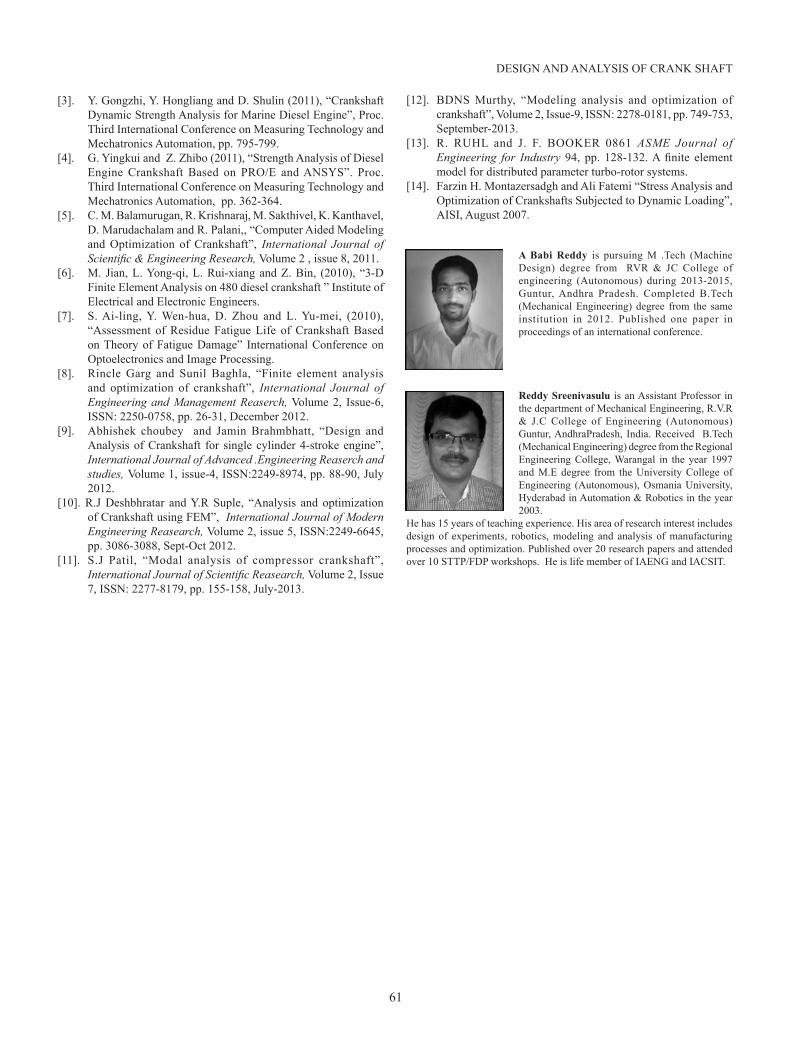
Variation of vonmises stresses
60
AKGEC INTERNATIONAL JOURNAL OF TECHNOLOGY, Vol. 6, No. 2
Figure 15. Variation of Von Mises stresses, total elastic strain and total deformation of the crankshafts.
From the above bar graph, we can conclude that the total equivalent stress developed in SAE3140 crankshaft is more compared to other crankshafts. During working condition of a crankshaft, stresses developed in it have to be as lowest as possible, out of the five crank shafts, the stresses developed in the titanium crankshaft are low compared to other four crankshafts.
From the above bar graph, we can conclude that the total elastic strain developed in SAE1045 crankshaft is more compared to other crankshafts. For any material crankshaft, during working condition, strain developed in it has to be as lowest as possible for longer durability, out of the five crankshafts, the total strain developed in the forged steel crankshaft is low compared to other crankshafts.
From the above bar graph, we can conclude that the total deformation produced in cast iron crankshaft is high compared to other crankshafts. For a repetitive working condition of a crankshaft, total deformation produced in it has to be as lowest as possible, out of the five crank shafts, total deformation produced in the forged steel crankshaft is low compared to other crankshafts. And also SAE1045 crankshaft deformation is almost same as forged steel, but with little difference. The material with lowest total deformation produced during working condition is forged steel crankshaft and next priority is SAE1045 crankshaft.
Variation of modal frequencies
Figure 16. Variation of modal frequencies of the five crankshafts.
Usually modal frequencies, determine the vibration characteristics of a component. For a moving part of an engine, at a particular mode, frequency has to be as lowest as possible to avoid noise and total failure. From the above graph, the vibration frequencies of cast iron crankshaft at a corresponding mode, compared to other crankshafts, are low. Modal frequencies of forged steel for corresponding modes are low compared to other crankshafts expect cast iron.
VII. CONCLUSIONFrom static analysis point of view, SAE1040 and forged steel crankshaft has the best results from the analyses carried out, compared to other crankshafts. From dynamic analysis point of view, the frequencies obtained in no load condition, obtained in case of forged steel for particular mode is very low compared to other crankshafts expect cast iron. This represents that forged steel has least vibrational characteristics. Lower the vibrational frequencies at corresponding mode, lower will be the prone to damage and noise.
VIII. REFERENCES [1]. A. Solanki, K. Tamboli and M. J. Zinjuwadia, (2011),
“Crankshaft Design and Optimization- A Review” National Conference on Recent Trends in Engineering & Technology.
[2] F.H. Montazersadgh and A. Fatemi, (2007), “Project Report on Stress Analysis and Optimization of Crankshafts Subject to Dynamic Loading” The University of Toledo.
61
DESIGN AND ANALYSIS OF CRANK SHAFT
[3]. Y. Gongzhi, Y. Hongliang and D. Shulin (2011), “Crankshaft Dynamic Strength Analysis for Marine Diesel Engine”, Proc. Third International Conference on Measuring Technology and Mechatronics Automation, pp. 795-799.
[4]. G. Yingkui and Z. Zhibo (2011), “Strength Analysis of Diesel Engine Crankshaft Based on PRO/E and ANSYS”. Proc. Third International Conference on Measuring Technology and Mechatronics Automation, pp. 362-364.
[5]. C. M. Balamurugan, R. Krishnaraj, M. Sakthivel, K. Kanthavel, D. Marudachalam and R. Palani,, “Computer Aided Modeling and Optimization of Crankshaft”, International Journal of Scientific & Engineering Research, Volume 2 , issue 8, 2011.
[6]. M. Jian, L. Yong-qi, L. Rui-xiang and Z. Bin, (2010), “3-D Finite Element Analysis on 480 diesel crankshaft ” Institute of Electrical and Electronic Engineers.
[7]. S. Ai-ling, Y. Wen-hua, D. Zhou and L. Yu-mei, (2010), “Assessment of Residue Fatigue Life of Crankshaft Based on Theory of Fatigue Damage” International Conference on Optoelectronics and Image Processing.
[8]. Rincle Garg and Sunil Baghla, “Finite element analysis and optimization of crankshaft”, International Journal of Engineering and Management Reaserch, Volume 2, Issue-6, ISSN: 2250-0758, pp. 26-31, December 2012.
[9]. Abhishek choubey and Jamin Brahmbhatt, “Design and Analysis of Crankshaft for single cylinder 4-stroke engine”, International Journal of Advanced .Engineering Reaserch and studies, Volume 1, issue-4, ISSN:2249-8974, pp. 88-90, July 2012.
[10]. R.J Deshbhratar and Y.R Suple, “Analysis and optimization of Crankshaft using FEM”, International Journal of Modern Engineering Reasearch, Volume 2, issue 5, ISSN:2249-6645, pp. 3086-3088, Sept-Oct 2012.
[11]. S.J Patil, “Modal analysis of compressor crankshaft”, International Journal of Scientific Reasearch, Volume 2, Issue 7, ISSN: 2277-8179, pp. 155-158, July-2013.
[12]. BDNS Murthy, “Modeling analysis and optimization of crankshaft”, Volume 2, Issue-9, ISSN: 2278-0181, pp. 749-753, September-2013.
[13]. R. RUHL and J. F. BOOKER 0861 ASME Journal of Engineering for Industry 94, pp. 128-132. A finite element model for distributed parameter turbo-rotor systems.
[14]. Farzin H. Montazersadgh and Ali Fatemi “Stress Analysis and Optimization of Crankshafts Subjected to Dynamic Loading”, AISI, August 2007.
A Babi Reddy is pursuing M .Tech (Machine Design) degree from RVR & JC College of engineering (Autonomous) during 2013-2015, Guntur, Andhra Pradesh. Completed B.Tech (Mechanical Engineering) degree from the same institution in 2012. Published one paper in proceedings of an international conference.
Reddy Sreenivasulu is an Assistant Professor in the department of Mechanical Engineering, R.V.R & J.C College of Engineering (Autonomous) Guntur, AndhraPradesh, India. Received B.Tech (Mechanical Engineering) degree from the Regional Engineering College, Warangal in the year 1997 and M.E degree from the University College of Engineering (Autonomous), Osmania University, Hyderabad in Automation & Robotics in the year 2003.
He has 15 years of teaching experience. His area of research interest includes design of experiments, robotics, modeling and analysis of manufacturing processes and optimization. Published over 20 research papers and attended over 10 STTP/FDP workshops. He is life member of IAENG and IACSIT.