b engine - boredmder - youtubeboredmder.com/fsms/nissan/altima/2002/em.pdfouter diameter of...
TRANSCRIPT
EM-1
ENGINE MECHANICAL
B ENGINE
CONTENTS
C
D
E
F
G
H
I
J
K
L
M
SECTION
A
EM
Revision: May 2004 2002 Altima
QR25DE
PRECAUTIONS .......................................................... 4Precautions for Draining Coolant ............................. 4Precautions for Disconnecting Fuel Piping .............. 4Precautions for Removal and Disassembly ............. 4Precautions for Inspection, Repair and Replace-ment ......................................................................... 4Precautions for Assembly and Installation ............... 4Parts Requiring Angular Tightening ......................... 4Precautions for Liquid Gasket .................................. 5
REMOVAL OF LIQUID GASKET SEALING .......... 5LIQUID GASKET APPLICATION PROCEDURE ..... 5
PREPARATION ........................................................... 6Special Service Tools ............................................... 6Commercial Service Tools ........................................ 9
NOISE, VIBRATION, AND HARSHNESS (NVH) TROUBLESHOOTING ...............................................11
NVH Troubleshooting — Engine Noise ...................11Use the Chart Below to Help You Find the Cause of the Symptom. ..................................................... 12
DRIVE BELTS ........................................................... 13Checking Drive Belts .............................................. 13Tension Adjustment ................................................ 13Removal and Installation ........................................ 13
REMOVAL ........................................................... 13INSTALLATION ................................................... 14
Removal and Installation of Drive Belt Auto-ten-sioner ..................................................................... 14
REMOVAL ........................................................... 14INSTALLATION ................................................... 14
AIR CLEANER AND AIR DUCT ............................... 16Removal and Installation ........................................ 16
REMOVAL ........................................................... 16INSTALLATION ................................................... 16CHANGING THE AIR CLEANER ELEMENT ...... 17
INTAKE MANIFOLD ................................................. 18Removal and Installation ........................................ 18
REMOVAL ........................................................... 18INSPECTION AFTER REMOVAL ....................... 20INSTALLATION ................................................... 20INSPECTION AFTER INSTALLATION ............... 22
EXHAUST MANIFOLD AND THREE WAY CATA-LYST .......................................................................... 23
Removal and Installation ........................................ 23REMOVAL ........................................................... 23INSPECTION AFTER REMOVAL ....................... 24INSTALLATION ................................................... 24
OIL PAN AND OIL STRAINER ................................. 25Removal and Installation ........................................ 25
REMOVAL ........................................................... 25INSPECTION AFTER REMOVAL ....................... 26INSTALLATION ................................................... 26INSPECTION AFTER INSTALLATION ................ 27
IGNITION COIL ......................................................... 28Removal and Installation ........................................ 28
REMOVAL ........................................................... 28INSTALLATION ................................................... 28
SPARK PLUG ........................................................... 29Removal and Installation ........................................ 29
REMOVAL ........................................................... 29INSPECTION AFTER REMOVAL ....................... 29INSTALLATION ................................................... 30
FUEL INJECTOR AND FUEL TUBE ........................ 31Removal and Installation ........................................ 31
REMOVAL ........................................................... 31INSTALLATION ................................................... 32INSPECTION AFTER INSTALLATION ................ 33
ROCKER COVER ..................................................... 34Removal and Installation ........................................ 34
REMOVAL ........................................................... 34INSTALLATION ................................................... 34
CAMSHAFT .............................................................. 36Removal and Installation ........................................ 36
REMOVAL ........................................................... 36INSPECTION AFTER REMOVAL ....................... 38
EM-2 Revision: May 2004 2002 Altima
INSTALLATION .................................................... 41Valve Clearance ...................................................... 43
INSPECTION ....................................................... 43ADJUSTMENT .................................................... 45
TIMING CHAIN .......................................................... 47Removal and Installation ........................................ 47
REMOVAL ........................................................... 48INSPECTION AFTER REMOVAL ........................ 50INSTALLATION .................................................... 50
CYLINDER HEAD ..................................................... 55On-Vehicle Service ................................................. 55
CHECKING COMPRESSION PRESSURE ......... 55Removal and Installation ........................................ 56
REMOVAL ........................................................... 56INSPECTION AFTER REMOVAL ........................ 57INSTALLATION .................................................... 57
Disassembly and Assembly .................................... 59DISASSEMBLY ................................................... 59ASSEMBLY ......................................................... 60
Inspection After Disassembly ................................. 60CYLINDER HEAD DISTORTION ........................ 60VALVE DIMENSIONS .......................................... 61VALVE GUIDE CLEARANCE .............................. 61VALVE GUIDE REPLACEMENT ......................... 61VALVE SEAT CONTACT ..................................... 62VALVE SEAT REPLACEMENT ........................... 63VALVE SPRING SQUARENESS ......................... 64VALVE SPRING DIMENSIONS AND VALVE SPRING PRESSURE LOAD ............................... 64
ENGINE ASSEMBLY ................................................ 65Removal and Installation ........................................ 65
REMOVAL ........................................................... 66INSTALLATION .................................................... 67INSPECTION AFTER INSTALLATION ................ 67
CYLINDER BLOCK ................................................... 69Disassembly and Assembly .................................... 69
DISASSEMBLY ................................................... 70ASSEMBLY ......................................................... 72
How to Select Piston and Bearing .......................... 77DESCRIPTION .................................................... 77HOW TO SELECT A PISTON ............................. 78HOW TO SELECT A CONNECTING ROD BEAR-ING ...................................................................... 78HOW TO SELECT A MAIN BEARING ................ 80
Inspection After Disassembly ................................. 83CRANKSHAFT SIDE CLEARANCE .................... 83CONNECTING ROD SIDE CLEARANCE ........... 84PISTON AND PISTON PIN CLEARANCE .......... 84PISTON RING SIDE CLEARANCE ..................... 85PISTON RING END GAP .................................... 85CONNECTING ROD BEND AND TORSION ....... 86CONNECTING ROD BEARING (BIG END) ........ 86CONNECTING ROD BUSHING OIL CLEAR-ANCE (SMALL END) ........................................... 86CYLINDER BLOCK DISTORTION ...................... 87INNER DIAMETER OF MAIN BEARING HOUS-ING ...................................................................... 88PISTON TO CYLINDER BORE CLEARANCE .... 88OUTER DIAMETER OF CRANKSHAFT JOUR-
NAL ......................................................................89OUTER DIAMETER OF CRANKSHAFT PIN ......89OUT-OF-ROUND AND TAPER OF CRANK-SHAFT .................................................................89CRANKSHAFT RUNOUT ....................................90OIL CLEARANCE OF CONNECTING ROD BEARING .............................................................90OIL CLEARANCE OF MAIN BEARING ...............90CRUSH HEIGHT OF MAIN BEARING ................91OUTER DIAMETER OF LOWER CYLINDER BLOCK MOUNTING BOLT ..................................91OUTER DIAMETER OF CONNECTING ROD BOLT ....................................................................91MOVEMENT AMOUNT OF FLYWHEEL (M/T MODEL) ...............................................................92
SERVICE DATA AND SPECIFICATIONS (SDS) ......93Standard and Limit ..................................................93
GENERAL SPECIFICATIONS .............................93INTAKE MANIFOLD AND EXHAUST MANI-FOLD ...................................................................93DRIVE BELTS ......................................................93CYLINDER HEAD ................................................94VALVE ..................................................................94CAMSHAFT AND CAMSHAFT BEARING ...........97CYLINDER BLOCK ..............................................97PISTON, PISTON RING, AND PISTON PIN ........98CONNECTING ROD ............................................99CRANKSHAFT ...................................................100MAIN BEARING .................................................101CONNECTING ROD BEARING .........................102
VQ35DE
PRECAUTIONS .......................................................103Precautions for Draining Coolant ..........................103Precautions for Disconnecting Fuel Piping ...........103Precautions for Removal and Disassembly ..........103Precautions for Inspection, Repair and Replace-ment ......................................................................103Precautions for Assembly and Installation ............103Parts Requiring Angular Tightening ......................103Precautions for Liquid Gasket ...............................104
REMOVAL OF LIQUID GASKET SEALING ......104LIQUID GASKET APPLICATION PROCEDURE .104
PREPARATION .......................................................105Special Service Tools ............................................105Commercial Service Tools ....................................107
NOISE, VIBRATION, AND HARSHNESS (NVH) TROUBLESHOOTING ............................................109
NVH Troubleshooting — Engine Noise .................109Use the Chart Below to Help You Find the Cause of the Symptom. .................................................... 110
DRIVE BELTS .......................................................... 111Checking Drive Belts ............................................. 111
AIR CLEANER AND AIR DUCT .............................112Removal and Installation ....................................... 112
REMOVAL .......................................................... 112INSTALLATION .................................................. 112CHANGING AIR CLEANER ELEMENT ............. 112
EM-3
C
D
E
F
G
H
I
J
K
L
M
EM
A
Revision: May 2004 2002 Altima
INTAKE MANIFOLD ................................................114Removal and Installation .......................................114
REMOVAL ..........................................................115INSPECTION AFTER REMOVAL ......................116INSTALLATION ..................................................116
EXHAUST MANIFOLD AND THREE WAY CATA-LYST ........................................................................118
Removal and Installation .......................................118REMOVAL ..........................................................119INSPECTION AFTER REMOVAL ..................... 120INSTALLATION ................................................. 121
OIL PAN .................................................................. 122Removal and Installation ...................................... 122
REMOVAL ......................................................... 122INSTALLATION ................................................. 125
IGNITION COIL ....................................................... 128Removal and Installation ...................................... 128
REMOVAL ......................................................... 128INSTALLATION ................................................. 128
SPARK PLUG (PLATINUM-TIPPED TYPE) ........... 129Removal and Installation ...................................... 129
REMOVAL ......................................................... 129INSPECTION AFTER REMOVAL ..................... 130INSTALLATION ................................................. 130
FUEL INJECTOR AND FUEL TUBE ...................... 131Removal and Installation ...................................... 131
REMOVAL ......................................................... 131INSTALLATION ................................................. 132INSPECTION AFTER INSTALLATION ............. 133
ROCKER COVER ................................................... 134Removal and Installation ...................................... 134
REMOVAL ......................................................... 134INSTALLATION ................................................. 135
CAMSHAFT ............................................................ 136Removal and Installation ...................................... 136
REMOVAL ......................................................... 137INSTALLATION ................................................. 137INSPECTION AFTER REMOVAL ..................... 141
Valve Clearance ................................................... 143CHECKING ....................................................... 143ADJUSTING ...................................................... 146
TIMING CHAIN ....................................................... 148Components ......................................................... 148
POSITION FOR APPLYING LIQUID GASKET . 150Removal ............................................................... 151Inspection ............................................................. 157Installation ............................................................ 157
CYLINDER HEAD ................................................... 166On-Vehicle Service ............................................... 166
CHECKING COMPRESSION PRESSURE ...... 166Removal and Installation ...................................... 167
REMOVAL ......................................................... 167INSTALLATION ................................................. 171
Disassembly and Assembly .................................. 178DISASSEMBLY ................................................. 179ASSEMBLY ....................................................... 179
Inspection After Disassembly ............................... 180CYLINDER HEAD DISTORTION ...................... 180VALVE GUIDE CLEARANCE ............................ 180VALVE GUIDE REPLACEMENT ....................... 181VALVE SEAT CONTACT ................................... 182VALVE SEAT REPLACEMENT ......................... 182VALVE SPRING SQUARENESS ....................... 183VALVE SPRING DIMENSIONS AND VALVE SPRING PRESSURE LOAD ............................. 183
ENGINE ASSEMBLY .............................................. 184Removal and Installation ...................................... 184
REMOVAL ......................................................... 185INSTALLATION ................................................. 187INSPECTION AFTER INSTALLATION .............. 187
CYLINDER BLOCK ................................................ 188Disassembly and Assembly .................................. 188
DISASSEMBLY ................................................. 189ASSEMBLY ....................................................... 191
Inspection ............................................................. 196PISTON AND PISTON PIN CLEARANCE ........ 196PISTON RING SIDE CLEARANCE ................... 197PISTON RING END GAP .................................. 197CONNECTING ROD BEND AND TORSION .... 197CONNECTING ROD BEARING (BIG END) ...... 198CONNECTING ROD BUSHING OIL CLEAR-ANCE (SMALL END) ......................................... 198CYLINDER BLOCK DISTORTION AND WEAR . 199INNER DIAMETER OF MAIN BEARING HOUS-ING .................................................................... 200PISTON-TO-BORE CLEARANCE ..................... 200CRANKSHAFT .................................................. 201BEARING CLEARANCE ................................... 202CONNECTING ROD BUSHING CLEARANCE (SMALL END) .................................................... 205DRIVE PLATE RUNOUT (A/T) .......................... 206FLYWHEEL RUNOUT (M/T) ............................. 206
SERVICE DATA AND SPECIFICATIONS (SDS) .... 208Standard and Limit ................................................ 208
GENERAL SPECIFICATIONS ........................... 208CYLINDER HEAD ............................................. 209VALVE ............................................................... 209CAMSHAFT AND CAMSHAFT BEARING ........ 213CYLINDER BLOCK ........................................... 213PISTON, PISTON RING AND PISTON PIN ...... 214CONNECTING ROD ......................................... 215CRANKSHAFT .................................................. 216AVAILABLE MAIN BEARING ............................ 217CONNECTING ROD BEARING ........................ 217MISCELLANEOUS COMPONENTS ................. 218BEARING CLEARANCE ................................... 218

EM-4 Revision: May 2004
[QR25DE]PRECAUTIONS
2002 Altima
PRECAUTIONS PFP:00001
Precautions for Draining Coolant EBS007OM
● Drain coolant when engine is cooled.
Precautions for Disconnecting Fuel Piping EBS007ON
● Before starting work, make sure no fire or spark producing items are in the work area. ● Release fuel pressure before any removal or disassembly.● After disconnecting pipes, plug openings to stop fuel leakage.
Precautions for Removal and Disassembly EBS007OO
● When instructed to use special service tools, use the specified tools. Always be careful to work safely,avoid forceful operations.
● Use maximum care to avoid damage to mating or sliding surfaces.● Cover openings of engine system with tape or equivalent, if necessary, to seal out foreign materials.● Mark and arrange disassembly parts in an organized way for easy troubleshooting and assembly.● When loosening nuts and bolts, as a basic rule, start with the one furthest outside, then the one diagonally
opposite, and so on. If the order of loosening is specified, follow the specifications.
Precautions for Inspection, Repair and Replacement EBS007OP
● Before repairing or replacing, thoroughly inspect parts. Inspect new replacement parts in the same way,and replace if necessary.
Precautions for Assembly and Installation EBS007OQ
● Use torque wrench to tighten bolts or nuts.● When tightening nuts and bolts, as a basic rule, equally tighten in several different steps starting with the
ones in center, then ones on inside and outside diagonally in this order. If the order of tightening is speci-fied, follow the specifications.
● Always replace the old with a new gasket, packing, oil seal or O-ring.● Thoroughly wash, clean, and air-blow each part. Carefully check oil or coolant passages for any restriction
and blockage. ● Avoid damaging sliding or mating surfaces. Completely remove foreign materials such as cloth lint or dust.
Before assembly, oil sliding surfaces well. ● Bleed the air trapped within the system after draining the coolant. ● After repairing, start engine and increase engine speed to check coolant, fuel, oil, and exhaust systems
for leakage or rattles.
Parts Requiring Angular Tightening EBS007OR
● Use an angle wrench for the final tightening of the following engine parts. – Cylinder head bolts– Lower cylinder block bolts– Connecting rod cap bolts– Crankshaft pulley bolt (No angle wrench is required as the bolt flange is provided with notches for angular
tightening)● Do not use a torque value for final tightening. ● The torque value for these parts are for a preliminary step.● Ensure thread and seat surfaces are clean and coated with engine oil.
PRECAUTIONS
EM-5
[QR25DE]
C
D
E
F
G
H
I
J
K
L
M
A
EM
Revision: May 2004 2002 Altima
Precautions for Liquid Gasket EBS007OS
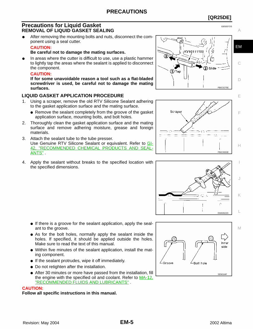
REMOVAL OF LIQUID GASKET SEALING● After removing the mounting bolts and nuts, disconnect the com-
ponent using a seal cutter. CAUTION:Be careful not to damage the mating surfaces.
● In areas where the cutter is difficult to use, use a plastic hammerto lightly tap the areas where the sealant is applied to disconnectthe component.CAUTION:If for some unavoidable reason a tool such as a flat-bladedscrewdriver is used, be careful not to damage the matingsurfaces.
LIQUID GASKET APPLICATION PROCEDURE1. Using a scraper, remove the old RTV Silicone Sealant adhering
to the gasket application surface and the mating surface.● Remove the sealant completely from the groove of the gasket
application surface, mounting bolts, and bolt holes.2. Thoroughly clean the gasket application surface and the mating
surface and remove adhering moisture, grease and foreignmaterials.
3. Attach the sealant tube to the tube presser.Use Genuine RTV Silicone Sealant or equivalent. Refer to GI-42, "RECOMMENDED CHEMICAL PRODUCTS AND SEAL-ANTS" .
4. Apply the sealant without breaks to the specified location withthe specified dimensions.
● If there is a groove for the sealant application, apply the seal-ant to the groove.
● As for the bolt holes, normally apply the sealant inside theholes. If specified, it should be applied outside the holes.Make sure to read the text of this manual.
● Within five minutes of the sealant application, install the mat-ing component.
● If the sealant protrudes, wipe it off immediately.● Do not retighten after the installation.● After 30 minutes or more have passed from the installation, fill
the engine with the specified oil and coolant. Refer to MA-12,"RECOMMENDED FLUIDS AND LUBRICANTS" .
CAUTION:Follow all specific instructions in this manual.
PBIC0275E
PBIC0003E
EMA0622D
SEM164F
EM-6 Revision: May 2004
[QR25DE]PREPARATION
2002 Altima
PREPARATION PFP:00002
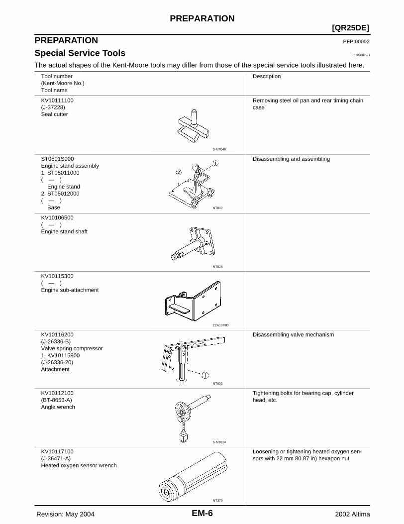
Special Service Tools EBS007OT
The actual shapes of the Kent-Moore tools may differ from those of the special service tools illustrated here.
Tool number(Kent-Moore No.)Tool name
Description
KV10111100(J-37228)Seal cutter
Removing steel oil pan and rear timing chain case
ST0501S000Engine stand assembly1, ST05011000( — ) Engine stand2, ST05012000( — ) Base
Disassembling and assembling
KV10106500( — )Engine stand shaft
KV10115300( — )Engine sub-attachment
KV10116200(J-26336-B)Valve spring compressor1, KV10115900(J-26336-20)Attachment
Disassembling valve mechanism
KV10112100(BT-8653-A)Angle wrench
Tightening bolts for bearing cap, cylinder head, etc.
KV10117100(J-36471-A)Heated oxygen sensor wrench
Loosening or tightening heated oxygen sen-sors with 22 mm 80.87 in) hexagon nut
S-NT046
NT042
NT028
ZZA1078D
NT022
S-NT014
NT379

PREPARATION
EM-7
[QR25DE]
C
D
E
F
G
H
I
J
K
L
M
A
EM
Revision: May 2004 2002 Altima
KV10107902(J-38959)Valve oil seal puller
Removing valve oil seal
KV10115600(J-38958)Valve oil seal drift
Installing valve oil sealUse side A.a: 20 (0.79) dia. d: 8 (0.31) dia.b: 13 (0.51) dia. e: 10.7 (0.421) dia.c: 10.3 (0.406) dia. f: 5 (0.20) dia. Unit: mm (in)
EM03470000(J-8037)Piston ring compressor
Installing piston assembly into cylinder bore
ST16610001(J-23907)Pilot bushing puller
Removing crankshaft pilot bushing
—(J-45737)TP50 Torx® plus bit
Removing and installing flywheel bolts (M/T models)
—(J-45816)E20 Torx® socket
Removing and installing drive plate bolts (A/T models)
Tool number(Kent-Moore No.)Tool name
Description
S-NT011
S-NT603
S-NT044
S-NT045
LBIA0284E
LBIA0285E
EM-8 Revision: May 2004
[QR25DE]PREPARATION
2002 Altima
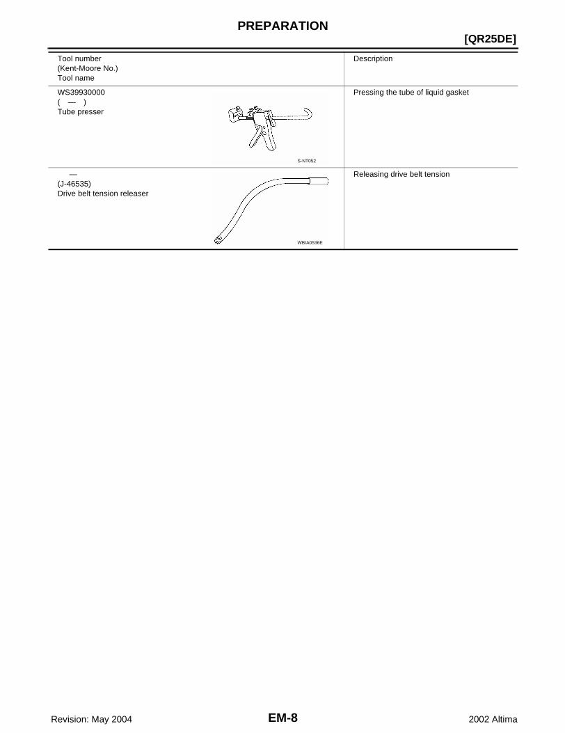
WS39930000( — )Tube presser
Pressing the tube of liquid gasket
—(J-46535)Drive belt tension releaser
Releasing drive belt tension
Tool number(Kent-Moore No.)Tool name
Description
S-NT052
WBIA0536E
PREPARATION
EM-9
[QR25DE]
C
D
E
F
G
H
I
J
K
L
M
A
EM
Revision: May 2004 2002 Altima
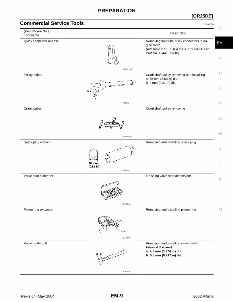
Commercial Service Tools EBS007OU
(Kent-Moore No.)Tool name
Description
Quick connector release Removing fuel tube quick connectors in en-gine room(Available in SEC. 164 of PARTS CATALOG: Part No. 16441 6N210)
Pulley holder Crankshaft pulley removing and installinga: 68 mm (2.68 in) dia.b: 8 mm (0.31 in) dia.
Crank puller Crankshaft pulley removing
Spark plug wrench Removing and installing spark plug
Valve seat cutter set Finishing valve seat dimensions
Piston ring expander Removing and installing piston ring
Valve guide drift Removing and installing valve guideIntake & Exhaust:a: 9.5 mm (0.374 in) dia.b: 5.5 mm (0.217 in) dia.
PBIC0198E
NT628
ZZA0010D
S-NT047
S-NT048
S-NT030
S-NT015
EM-10 Revision: May 2004
[QR25DE]PREPARATION
2002 Altima
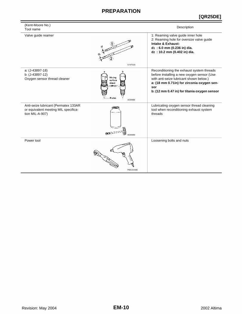
Valve guide reamer 1: Reaming valve guide inner hole2: Reaming hole for oversize valve guide Intake & Exhaust:d1 : 6.0 mm (0.236 in) dia.d2 : 10.2 mm (0.402 in) dia.
a: (J-43897-18)b: (J-43897-12)Oxygen sensor thread cleaner
Reconditioning the exhaust system threads before installing a new oxygen sensor (Use with anti-seize lubricant shown below.)a: (18 mm 0.71in) for zirconia oxygen sen-sorb: (12 mm 0.47 in) for titania oxygen sensor
Anti-seize lubricant (Permatex 133AR or equivalent meeting MIL specifica-tion MIL-A-907)
Lubricating oxygen sensor thread cleaning tool when reconditioning exhaust system threads
Power tool Loosening bolts and nuts
(Kent-Moore No.)Tool name
Description
S-NT016
AEM488
AEM489
PBIC0190E

NOISE, VIBRATION, AND HARSHNESS (NVH) TROUBLESHOOTING
EM-11
[QR25DE]
C
D
E
F
G
H
I
J
K
L
M
A
EM
Revision: May 2004 2002 Altima
NOISE, VIBRATION, AND HARSHNESS (NVH) TROUBLESHOOTING PFP:00003
NVH Troubleshooting — Engine Noise EBS007OV
WBIA0069E
EM-12 Revision: May 2004
[QR25DE]NOISE, VIBRATION, AND HARSHNESS (NVH) TROUBLESHOOTING
2002 Altima
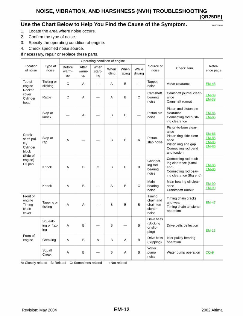
Use the Chart Below to Help You Find the Cause of the Symptom. EBS007OW
1. Locate the area where noise occurs.2. Confirm the type of noise.3. Specify the operating condition of engine.4. Check specified noise source.If necessary, repair or replace these parts.
A: Closely related B: Related C: Sometimes related —: Not related
Location of noise
Type of noise
Operating condition of engine
Source of noise
Check itemRefer-
ence pageBefore warm-
up
After warm-
up
When start-ing
When idling
When racing
While driving
Top of engineRocker coverCylinder head
Ticking or clicking
C A — A B —Tappet noise
Valve clearance EM-43
Rattle C A — A B CCamshaft bearing noise
Camshaft journal clear-anceCamshaft runout
EM-39EM-38
Crank-shaft pul-leyCylinder block (Side of engine)Oil pan
Slap or knock
— A — B B —Piston pin noise
Piston and piston pin clearanceConnecting rod bush-ing clearance
EM-86EM-86
Slap or rap
A — — B B APiston slap noise
Piston-to-bore clear-ancePiston ring side clear-ancePiston ring end gapConnecting rod bend and torsion
EM-86EM-85EM-85EM-86
Knock A B C B B B
Connect-ing rod bearing noise
Connecting rod bush-ing clearance (Small end)Connecting rod bear-ing clearance (Big end)
EM-86EM-86
Knock A B — A B CMain bearing noise
Main bearing oil clear-anceCrankshaft runout
EM-90EM-90
Front of engineTiming chain cover
Tapping or ticking
A A — B B B
Timing chain and chain ten-sioner noise
Timing chain cracks and wearTiming chain tensioner operation
EM-47
Front of engine
Squeak-ing or fizz-ing
A B — B — B
Drive belts (Sticking or slip-ping)
Drive belts deflection
EM-13
Creaking A B A B A BDrive belts (Slipping)
Idler pulley bearing operation
SquallCreak
A B — B A BWater pump noise
Water pump operation CO-9

DRIVE BELTS
EM-13
[QR25DE]
C
D
E
F
G
H
I
J
K
L
M
A
EM
Revision: May 2004 2002 Altima
DRIVE BELTS PFP:02117
Checking Drive Belts EBS00KB9
NOTE:On vehicles not equipped with A/C, there is an idler pulley in the position for the drive belt routing.WARNING:Inspect the drive belt only when the engine is stopped.● Make sure that the stamp mark of drive belt auto-tensioner is within the usable range.
NOTE:● Check the drive belt auto-tensioner indication when the engine is cold.● When the new drive belt is installed, the range should be A.● Visually check entire belt for wear, damage or cracks.● If the indicator is out of allowable use range or belt is damaged, replace the belt.
Tension Adjustment EBS00KBA
Belt tension is not manually adjustable, it is automatically adjusted by the drive belt auto-tensioner.
Removal and Installation EBS00KBB
REMOVAL1. Remove front RH engine side cover.2. While securely holding the hexagonal part in pulley center of
drive belt auto-tensioner, move in the direction of arrow (loosen-ing direction of tensioner) using Tool.
CAUTION:● Avoid placing hand in a location where pinching may
occur if the holding tool accidentally comes off.● Do not loosen the auto-tensioner pulley bolt. (Do not turn
it counterclockwise.) If turned counterclockwise, thecomplete auto-tensioner must be replaced as a unit,including pulley.
3. Insert a rod approximately 6 mm (0.24 in) in diameter through the rear of tensioner into retaining boss tolock tensioner pulley.NOTE:Leave tensioner pulley arm locked until belt is installed again.
4. Loosen auxiliary drive belt from water pump pulley in sequence, and remove it.
SBIA0234E
Tool number : — (J-46535)
WBIA0561E

EM-14 Revision: May 2004
[QR25DE]DRIVE BELTS
2002 Altima
INSTALLATIONInstallation is in the reverse order of removal.CAUTION:● Do not loosen the auto-tensioner pulley bolt. (Do not turn it counterclockwise.) If turned counter-
clockwise, the complete auto-tensioner must be replaced as a unit, including pulley.● Avoid placing hand in a location where pinching may occur if the holding tool accidentally comes
off.● Confirm belts are completely set on the pulleys.NOTE:● Turn crankshaft pulley clockwise several times to equalize tension between each pulley.● Confirm tension of drive belt at indicator (notch on fixed side) is within the possible use range. Refer to
EM-13 .
Removal and Installation of Drive Belt Auto-tensioner EBS00KBC
CAUTION:The complete auto-tensioner must be replaced as a unit, including the pulley.
REMOVAL1. Remove the front RH engine side cover.2. Remove the drive belt. Refer to EM-13 .3. Remove the alternator. Refer to SC-34, "Removal" .4. Remove the drive belt auto-tensioner, using power tool.CAUTION:Do not loosen the auto-tensioner pulley bolt. (Do not turn it counterclockwise.) If turned counterclock-wise, the complete auto-tensioner must be replaced as a unit, including pulley.
INSTALLATION1. Install drive belt auto-tensioner.2. While securely holding the hexagonal part in pulley center of drive belt auto-tensioner, move in the direc-
tion of arrow (loosening direction of tensioner) using Tool.
CAUTION:● Avoid placing hand in a location where pinching may occur if the holding tool accidentally comes
off.
SBIA0235E
Tool number : — (J-46535)
DRIVE BELTS
EM-15
[QR25DE]
C
D
E
F
G
H
I
J
K
L
M
A
EM
Revision: May 2004 2002 Altima
● Do not loosen the auto-tensioner pulley bolt. (Do not turn it counterclockwise.) If turned counter-clockwise, the complete auto-tensioner must be replaced as a unit, including pulley.
3. Insert a rod approximately 6 mm (0.24 in) in diameter through the rear of tensioner into retaining boss tolock tensioner pulley.NOTE:Leave tensioner pulley arm locked until belt is installed.
CAUTION:● Install the drive belt auto-tensioner carefully so not to damage the water pump pulley.● If there is damage greater than peeled paint, replace the drive belt auto-tensioner.● Do not swap the pulley between the new and old auto-tensioner unit.4. Installation of the remaining components is in the reverse order of removal.
EM-16 Revision: May 2004
[QR25DE]AIR CLEANER AND AIR DUCT
2002 Altima
AIR CLEANER AND AIR DUCT PFP:16500
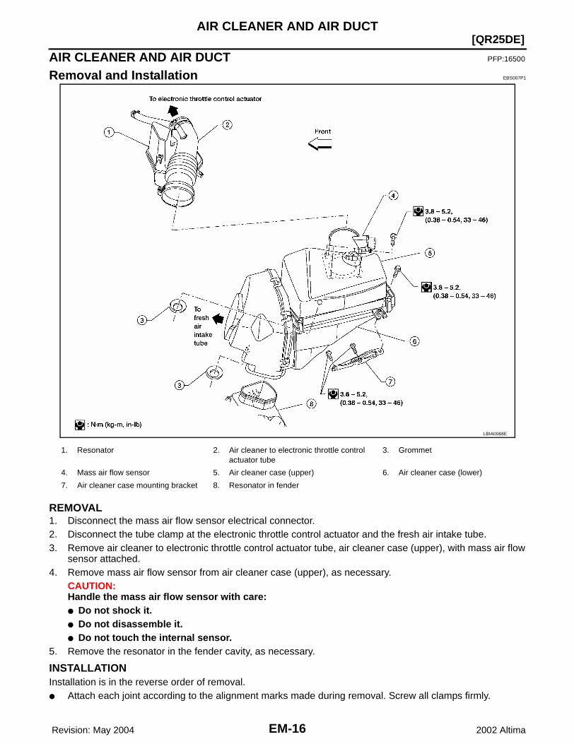
Removal and Installation EBS007P1
REMOVAL1. Disconnect the mass air flow sensor electrical connector.2. Disconnect the tube clamp at the electronic throttle control actuator and the fresh air intake tube.3. Remove air cleaner to electronic throttle control actuator tube, air cleaner case (upper), with mass air flow
sensor attached.4. Remove mass air flow sensor from air cleaner case (upper), as necessary.
CAUTION:Handle the mass air flow sensor with care:● Do not shock it.● Do not disassemble it.● Do not touch the internal sensor.
5. Remove the resonator in the fender cavity, as necessary.
INSTALLATIONInstallation is in the reverse order of removal.● Attach each joint according to the alignment marks made during removal. Screw all clamps firmly.
LBIA0068E
1. Resonator 2. Air cleaner to electronic throttle control actuator tube
3. Grommet
4. Mass air flow sensor 5. Air cleaner case (upper) 6. Air cleaner case (lower)
7. Air cleaner case mounting bracket 8. Resonator in fender

AIR CLEANER AND AIR DUCT
EM-17
[QR25DE]
C
D
E
F
G
H
I
J
K
L
M
A
EM
Revision: May 2004 2002 Altima
CHANGING THE AIR CLEANER ELEMENT1. Unhook the air cleaner case side clips and raise the air cleaner case (upper).2. Remove the air cleaner element.3. Install the new element, facing in the direction indicated on the element4. position the air cleaner case (upper) and secure the air cleaner case side clips.
EM-18 Revision: May 2004
[QR25DE]INTAKE MANIFOLD
2002 Altima
INTAKE MANIFOLD PFP:14003
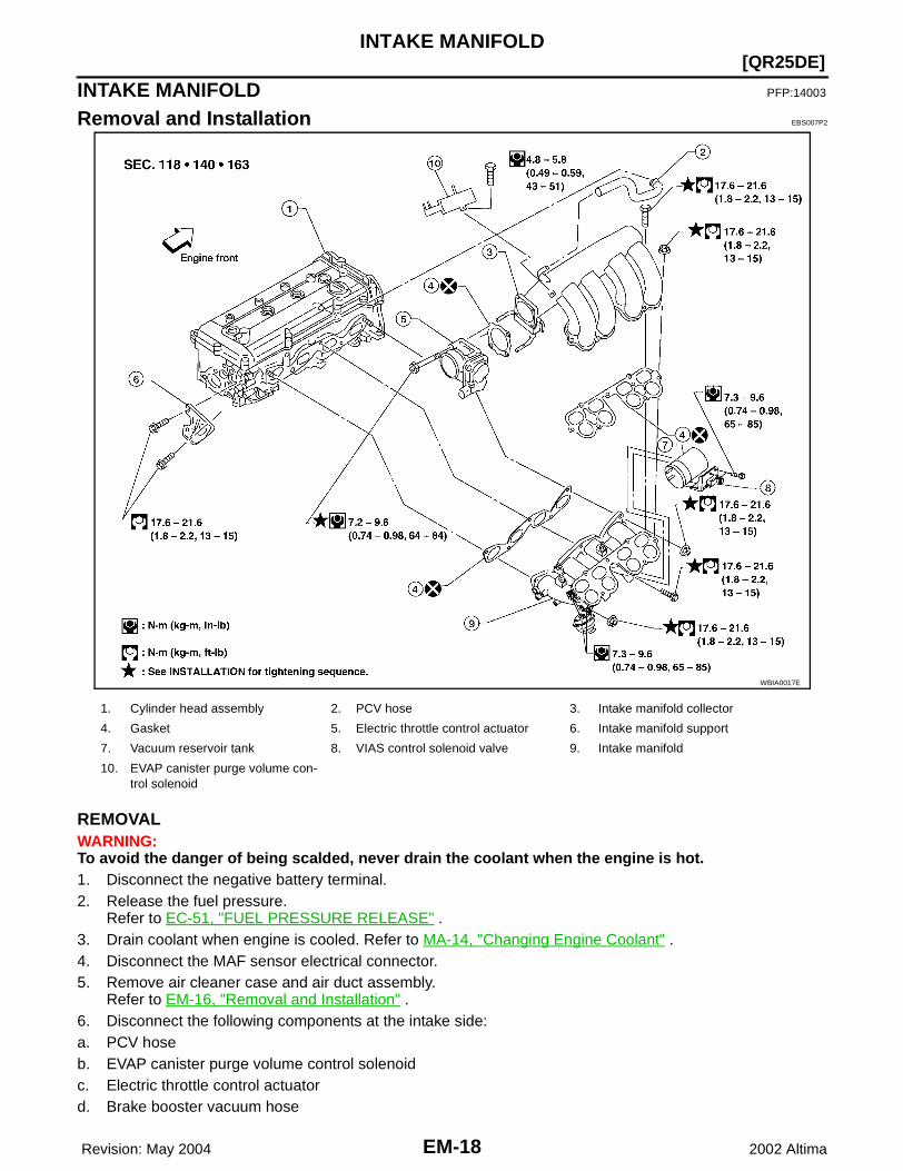
Removal and Installation EBS007P2
REMOVALWARNING:To avoid the danger of being scalded, never drain the coolant when the engine is hot.1. Disconnect the negative battery terminal.2. Release the fuel pressure.
Refer to EC-51, "FUEL PRESSURE RELEASE" .3. Drain coolant when engine is cooled. Refer to MA-14, "Changing Engine Coolant" .4. Disconnect the MAF sensor electrical connector.5. Remove air cleaner case and air duct assembly.
Refer to EM-16, "Removal and Installation" .6. Disconnect the following components at the intake side:a. PCV hoseb. EVAP canister purge volume control solenoidc. Electric throttle control actuatord. Brake booster vacuum hose
WBIA0017E
1. Cylinder head assembly 2. PCV hose 3. Intake manifold collector
4. Gasket 5. Electric throttle control actuator 6. Intake manifold support
7. Vacuum reservoir tank 8. VIAS control solenoid valve 9. Intake manifold
10. EVAP canister purge volume con-trol solenoid

INTAKE MANIFOLD
EM-19
[QR25DE]
C
D
E
F
G
H
I
J
K
L
M
A
EM
Revision: May 2004 2002 Altima
7. Disconnect fuel hose quick connector on the vehicle engineside.● Using the quick connector release tool (here after called
“release tool”), and perform the following steps to disconnectthe fuel tube quick connector.
a. Remove quick connector cap.
b. With the sleeve side of release facing quick connector, installrelease tool onto the fuel tube as shown.
c. Insert release tool into quick connector until sleeve contacts andgoes no further. Hold the release tool on that position.CAUTION:Inserting the release tool hard will not disconnect quickconnector. Hold release tool where it contacts and goes nofurther.
d. Pull the quick connector straight out from the fuel tube.CAUTION:● Pull quick connector holding it at the "A" position, as
shown.● Do not pull with lateral force applied. O-ring inside quick connector may be damaged.● Prepare container and cloth beforehand as fuel will leak out.● Avoid fire and sparks.● Be sure to cover openings of disconnected pipes with plug or plastic bag to avoid fuel leakage
and entry of foreign materials.
8. If necessary, disconnect the fuel tube, on the vehicle piping side, using the quick connector release tool(here after called "release tool"). Perform the following steps to disconnect the fuel tube quick connector.
a. With the sleeve side of the release facing quick connector, installrelease tool onto the fuel tube as shown.
b. Insert release tool into quick connector until sleeve contacts andgoes no further. Hold the release tool on that position.CAUTION:Inserting the release tool hard will not disconnect quickconnector. Hold release tool where it contacts and goes nofurther.
c. Pull the quick connector straight out off of the fuel tube.CAUTION:● Pull quick connector holding it at the "A" position, as
shown.
KBIA0268E
LBIA0090E
LBIA0089E
LBIA0089E

EM-20 Revision: May 2004
[QR25DE]INTAKE MANIFOLD
2002 Altima
● Do not pull with lateral force applied as the O-ring inside the quick connector may be damaged.● Prepare a container and cloth beforehand as fuel will leak out.● Avoid fire and sparks.● Be sure to cover openings of disconnected pipes with plug or plastic bag to avoid fuel leakage
and entry of foreign materials.9. Loosen mounting bolts diagonally, and remove the electric throttle control actuator.
CAUTION:Handle carefully to avoid any damage.
10. Disconnect intake manifold collector harness, and vacuum hose.CAUTION:Cover engine openings to avoid entry of foreign materials.
11. Remove intake manifold collector mounting bolts on the support, using power tools.12. Loosen the mounting bolts and nuts in the order shown to
remove the intake manifold collector, using power tools.
13. Loosen the bolts in the order shown to remove the intake mani-fold assembly, using power tools.
INSPECTION AFTER REMOVALSurface Distortion● Using straightedge and feeler gauge, inspect surface distortion
of intake manifold collector and intake manifold surface.
INSTALLATIONInstall the intake manifold bolts and nuts in the reverse order of removal, following the tightening sequencesbelow.
WBIA0018E
WBIA0019E
Standard : 0.1 mm (0.004 in)
WBIA0020E
INTAKE MANIFOLD
EM-21
[QR25DE]
C
D
E
F
G
H
I
J
K
L
M
A
EM
Revision: May 2004 2002 Altima
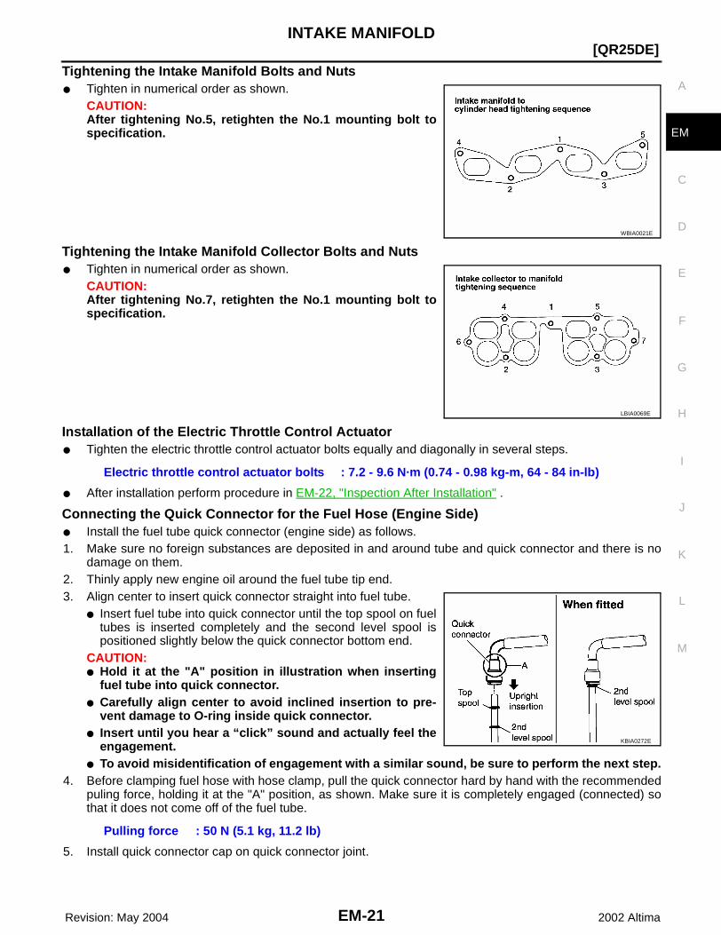
Tightening the Intake Manifold Bolts and Nuts● Tighten in numerical order as shown.
CAUTION:After tightening No.5, retighten the No.1 mounting bolt tospecification.
Tightening the Intake Manifold Collector Bolts and Nuts● Tighten in numerical order as shown.
CAUTION:After tightening No.7, retighten the No.1 mounting bolt tospecification.
Installation of the Electric Throttle Control Actuator● Tighten the electric throttle control actuator bolts equally and diagonally in several steps.
● After installation perform procedure in EM-22, "Inspection After Installation" .
Connecting the Quick Connector for the Fuel Hose (Engine Side)● Install the fuel tube quick connector (engine side) as follows.1. Make sure no foreign substances are deposited in and around tube and quick connector and there is no
damage on them. 2. Thinly apply new engine oil around the fuel tube tip end.3. Align center to insert quick connector straight into fuel tube.
● Insert fuel tube into quick connector until the top spool on fueltubes is inserted completely and the second level spool ispositioned slightly below the quick connector bottom end.
CAUTION:● Hold it at the "A" position in illustration when inserting
fuel tube into quick connector.● Carefully align center to avoid inclined insertion to pre-
vent damage to O-ring inside quick connector.● Insert until you hear a “click” sound and actually feel the
engagement.● To avoid misidentification of engagement with a similar sound, be sure to perform the next step.
4. Before clamping fuel hose with hose clamp, pull the quick connector hard by hand with the recommendedpuling force, holding it at the "A" position, as shown. Make sure it is completely engaged (connected) sothat it does not come off of the fuel tube.
5. Install quick connector cap on quick connector joint.
WBIA0021E
LBIA0069E
Electric throttle control actuator bolts : 7.2 - 9.6 N·m (0.74 - 0.98 kg-m, 64 - 84 in-lb)
Pulling force : 50 N (5.1 kg, 11.2 lb)
KBIA0272E

EM-22 Revision: May 2004
[QR25DE]INTAKE MANIFOLD
2002 Altima
● Direct arrow mark on quick connector cap to upper side (fuelhose side).
6. Install fuel hose to hose clamp.
Connecting the Quick Connector for the Fuel Hose (Vehicle Piping Side)● Install the fuel tube quick connector (vehicle piping side) as follows.1. Make sure no foreign substances are deposited in and around tube and quick connector and there is no
damage on them. 2. Thinly apply new engine oil around the fuel tube tip end.3. Align center to insert quick connector straight into fuel tube.
● Insert fuel tube into quick connector until the top spool on fueltubes is inserted completely and the paint mark is positionedslightly below the quick connector bottom end.
CAUTION:● Carefully align center to avoid inclined insertion to pre-
vent damage to O-ring inside quick connector.● Insert until you hear a “click” sound and actually feel the
engagement.● To avoid misidentification of engagement with a similar
sound, be sure to perform the next step.4. Before clamping fuel hose with hose clamp, pull the quick connector hard by hand with the recommended
pulling force. Make sure it is completely engaged (connected) so that it does not come off of the fuel tube.
INSPECTION AFTER INSTALLATION1. Start the engine and run it for a few minutes with the engine at idle.
● Check connections for fuel leakage.2. Stop the engine and check for fuel leakage both visually and by odor of gasoline.
● Perform procedures for “Throttle Valve Closed Position Learning” after finishing repairs. Refer to EC-49, "Throttle Valve Closed Position Learning" .
● If electric throttle control actuator is replaced, perform procedures for “Idle Air Volume Learning” afterfinishing repairs. Refer to EC-49, "Idle Air Volume Learning" .
NOTE:Use mirrors for checking on connections out of the direct line of sight.CAUTION:Do not touch engine immediately after stopped, as engine becomes extremely hot.
KBIA0298E
Pulling force : 50 N (5.1 kg, 11.2 lb
PBIC0017E

EXHAUST MANIFOLD AND THREE WAY CATALYST
EM-23
[QR25DE]
C
D
E
F
G
H
I
J
K
L
M
A
EM
Revision: May 2004 2002 Altima
EXHAUST MANIFOLD AND THREE WAY CATALYST PFP:14004
Removal and Installation EBS007P3
REMOVAL1. Remove engine under cover, with power tool.2. Disconnect the electrical connector of each heated oxygen sensor, and unhook the harness from the
bracket and middle clamp on the cover.3. Remove the heated oxygen sensors with Tool.
CAUTION:● Be careful not to damage heated oxygen sensor.● Discard any heated oxygen sensor which has been
dropped from a height of more than 0.5 m (19.7 in) onto ahard surface such as a concrete floor; use a new one.
4. Remove the lower exhaust manifold cover.5. Remove the exhaust front tube. Refer to EX-3, "Removal and
Installation" .6. Remove the upper exhaust manifold cover.
WBIA0242E
1. Exhaust manifold and three way catalyst assembly
2. Exhaust manifold gasket 3. Exhaust manifold cover (upper and lower)
4. Heated oxygen sensor 1 (front) 5. Heated oxygen sensor 2 (rear)
KBIA0094E

EM-24 Revision: May 2004
[QR25DE]EXHAUST MANIFOLD AND THREE WAY CATALYST
2002 Altima
7. Loosen the nuts in the sequence shown, on the exhaust mani-fold and three way catalyst.
8. Remove the exhaust manifold and three way catalyst assemblyand gasket. Discard the gasket.
INSPECTION AFTER REMOVALSurface Distortion● Use a reliable straightedge and feeler gauge to check the flat-
ness of exhaust manifold fitting surface.
INSTALLATIONInstallation is in the reverse order of removal. Pay attention to the following.
Tightening the Exhaust Manifold Bolts● Tighten the nuts in the numerical order shown, to specification.
After tightening No. 5, retighten No. 1 and then No. 3 to specifi-cation.
Installation of the Heated Oxygen SensorsClean the heated oxygen sensor threads with the Tool, then apply the anti-seize lubricant to the threads beforeinstalling the heated oxygen sensors.CAUTION:Do not over-tighten the heated oxygen sensors. Doing so may cause damage to the heated oxygensensors, resulting in a malfunction and the MIL coming on.
WBIA0022E
Standard : 0.3 mm (0.012 in)
KBIA0046E
WBIA0023E

OIL PAN AND OIL STRAINER
EM-25
[QR25DE]
C
D
E
F
G
H
I
J
K
L
M
A
EM
Revision: May 2004 2002 Altima
OIL PAN AND OIL STRAINER PFP:11110
Removal and Installation EBS007P4
REMOVALWARNING:To avoid the danger of being scalded, never drain the engine oil when the engine is hot.1. Remove the engine under covers on both sides, using power tool.2. Drain engine oil. Refer to LU-7, "Changing Engine Oil" .3. Remove the front exhaust tube. Refer to EX-3, "Removal and Installation" .4. Remove the front suspension member, using power tool.a. Unhook the power steering reservoir from the mounting bracket and reposition it lower to add slack to the
power steering lines.b. Disconnect the A/C compressor with piping connected from the mounting bracket and suspend with a
strong wire. Refer toMTC-83, "Removal and Installation for Compressor — QR25DE Models" .c. Disconnect the upper swaybar links. Refer to FSU-11, "Removal and Installation" .d. Remove the front and rear engine mount through bolts while supporting the front suspension member with
a suitable jack and tools. Refer to EM-65, "Removal and Installation" .e. Disconnect the lower ball joints. Refer to FSU-14, "Removal and Installation" .f. Remove the two steering gear mounting bolts (do not remove the mounting bracket from the steering gear
housing). Refer to PS-13, "Removal and Installation" .
KBIA0095E
1. Oil dipstick tube 2. Oil pan, upper 3. Cylinder block
4. Oil filter 5. Oil pickup screen 6. Drain plug
7. Oil pan, lower 8. Rear plate cover
EM-26 Revision: May 2004
[QR25DE]OIL PAN AND OIL STRAINER
2002 Altima
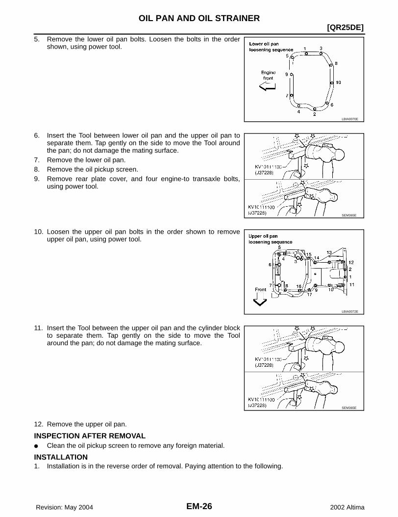
5. Remove the lower oil pan bolts. Loosen the bolts in the ordershown, using power tool.
6. Insert the Tool between lower oil pan and the upper oil pan toseparate them. Tap gently on the side to move the Tool aroundthe pan; do not damage the mating surface.
7. Remove the lower oil pan.8. Remove the oil pickup screen.9. Remove rear plate cover, and four engine-to transaxle bolts,
using power tool.
10. Loosen the upper oil pan bolts in the order shown to removeupper oil pan, using power tool.
11. Insert the Tool between the upper oil pan and the cylinder blockto separate them. Tap gently on the side to move the Toolaround the pan; do not damage the mating surface.
12. Remove the upper oil pan.
INSPECTION AFTER REMOVAL● Clean the oil pickup screen to remove any foreign material.
INSTALLATION1. Installation is in the reverse order of removal. Paying attention to the following.
LBIA0070E
SEM365E
LBIA0072E
SEM365E
OIL PAN AND OIL STRAINER
EM-27
[QR25DE]
C
D
E
F
G
H
I
J
K
L
M
A
EM
Revision: May 2004 2002 Altima
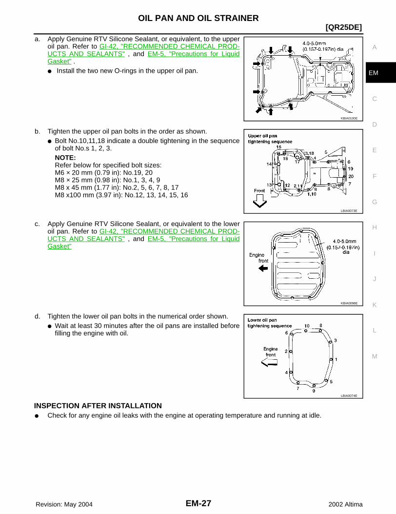
a. Apply Genuine RTV Silicone Sealant, or equivalent, to the upperoil pan. Refer to GI-42, "RECOMMENDED CHEMICAL PROD-UCTS AND SEALANTS" , and EM-5, "Precautions for LiquidGasket" .● Install the two new O-rings in the upper oil pan.
b. Tighten the upper oil pan bolts in the order as shown.● Bolt No.10,11,18 indicate a double tightening in the sequence
of bolt No.s 1, 2, 3.NOTE:Refer below for specified bolt sizes:M6 × 20 mm (0.79 in): No.19, 20M8 × 25 mm (0.98 in): No.1, 3, 4, 9M8 x 45 mm (1.77 in): No.2, 5, 6, 7, 8, 17M8 x100 mm (3.97 in): No.12, 13, 14, 15, 16
c. Apply Genuine RTV Silicone Sealant, or equivalent to the loweroil pan. Refer to GI-42, "RECOMMENDED CHEMICAL PROD-UCTS AND SEALANTS" , and EM-5, "Precautions for LiquidGasket"
d. Tighten the lower oil pan bolts in the numerical order shown.● Wait at least 30 minutes after the oil pans are installed before
filling the engine with oil.
INSPECTION AFTER INSTALLATION● Check for any engine oil leaks with the engine at operating temperature and running at idle.
KBIA0100E
LBIA0073E
KBIA0098E
LBIA0074E
EM-28 Revision: May 2004
[QR25DE]IGNITION COIL
2002 Altima
IGNITION COIL PFP:22448
Removal and Installation EBS007P5
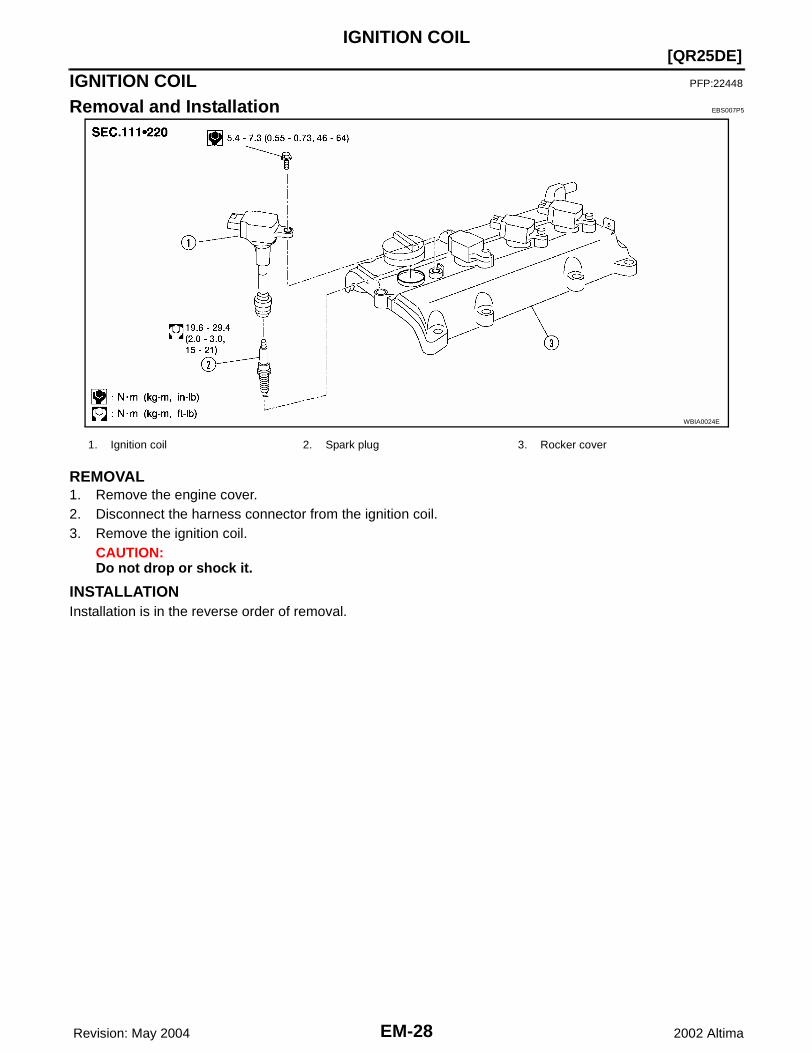
REMOVAL1. Remove the engine cover.2. Disconnect the harness connector from the ignition coil.3. Remove the ignition coil.
CAUTION:Do not drop or shock it.
INSTALLATIONInstallation is in the reverse order of removal.
WBIA0024E
1. Ignition coil 2. Spark plug 3. Rocker cover

SPARK PLUG
EM-29
[QR25DE]
C
D
E
F
G
H
I
J
K
L
M
A
EM
Revision: May 2004 2002 Altima
SPARK PLUG PFP:22401
Removal and Installation EBS007P6
REMOVAL1. Remove the ignition coil. Refer to EM-28, "Removal and Installation" .2. Remove the spark plug with a suitable spark plug socket and
wrench.
INSPECTION AFTER REMOVALUse standard type spark plug for normal conditions.The hot type spark plug is suitable when fouling occurs with the standard type spark plug under conditionssuch as:● frequent engine starts.● low ambient temperatures.The cold type spark plug is suitable when spark plug knock occurs with the standard type spark plug underconditions such as:● extended highway driving.● frequent high engine revolution.
WBIA0024E
1. Ignition coil 2. Spark plug 3. Rocker cover
Temperature Range NGK
Standard type PLFR5A-11
Hot type PLFR4A-11
Cold type PLFR6A-11
SEM294A
EM-30 Revision: May 2004
[QR25DE]SPARK PLUG
2002 Altima
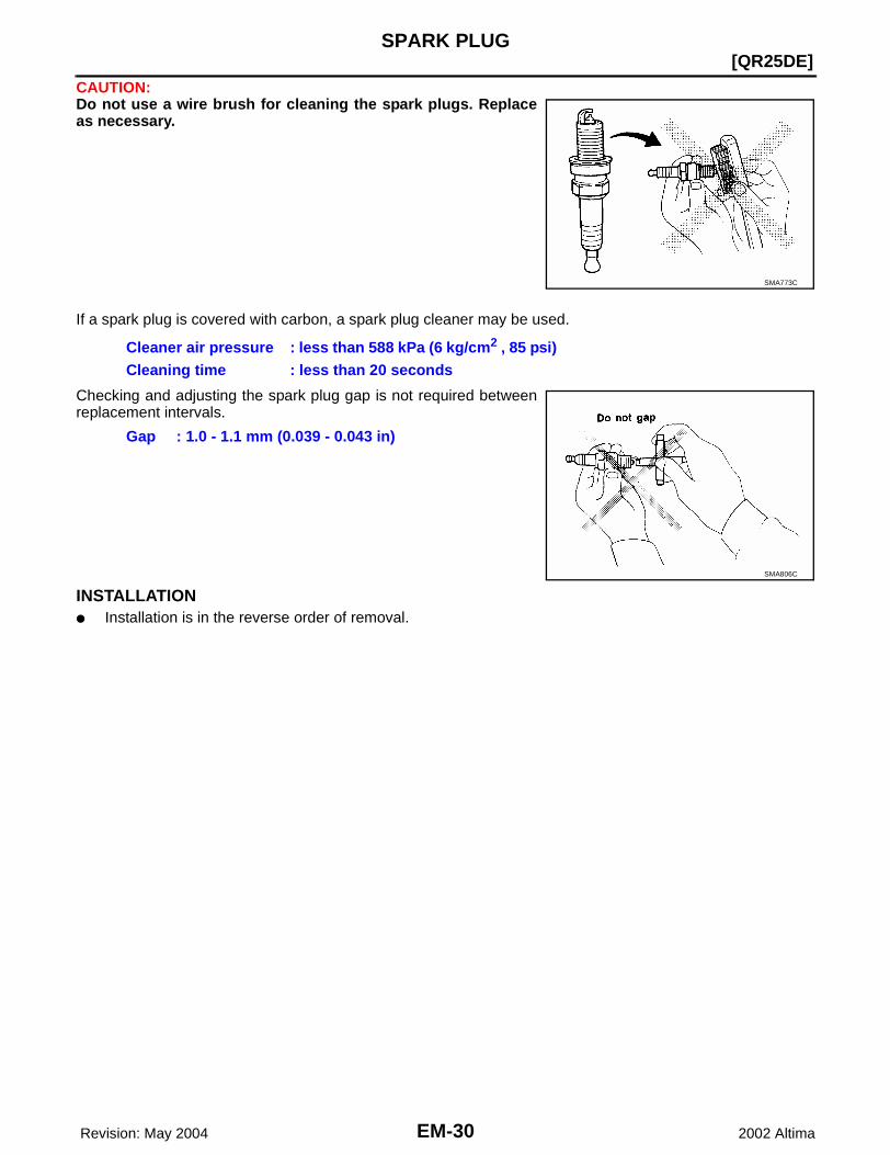
CAUTION:Do not use a wire brush for cleaning the spark plugs. Replaceas necessary.
If a spark plug is covered with carbon, a spark plug cleaner may be used.
Checking and adjusting the spark plug gap is not required betweenreplacement intervals.
INSTALLATION● Installation is in the reverse order of removal.
SMA773C
Cleaner air pressure : less than 588 kPa (6 kg/cm2 , 85 psi)Cleaning time : less than 20 seconds
Gap : 1.0 - 1.1 mm (0.039 - 0.043 in)
SMA806C
FUEL INJECTOR AND FUEL TUBE
EM-31
[QR25DE]
C
D
E
F
G
H
I
J
K
L
M
A
EM
Revision: May 2004 2002 Altima
FUEL INJECTOR AND FUEL TUBE PFP:16600
Removal and Installation EBS007P7
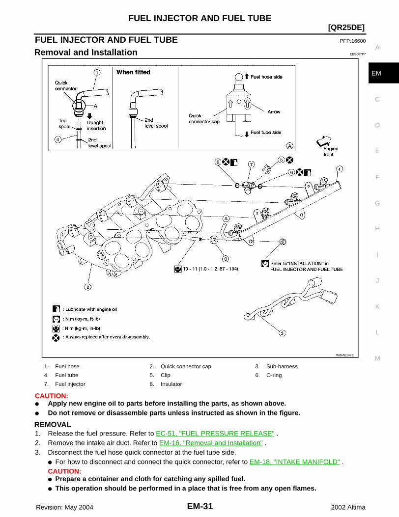
CAUTION:● Apply new engine oil to parts before installing the parts, as shown above.● Do not remove or disassemble parts unless instructed as shown in the figure.
REMOVAL1. Release the fuel pressure. Refer to EC-51, "FUEL PRESSURE RELEASE" .2. Remove the intake air duct. Refer to EM-16, "Removal and Installation" .3. Disconnect the fuel hose quick connector at the fuel tube side.
● For how to disconnect and connect the quick connector, refer to EM-18, "INTAKE MANIFOLD" .CAUTION:● Prepare a container and cloth for catching any spilled fuel.● This operation should be performed in a place that is free from any open flames.
WBIA0147E
1. Fuel hose 2. Quick connector cap 3. Sub-harness
4. Fuel tube 5. Clip 6. O-ring
7. Fuel injector 8. Insulator

EM-32 Revision: May 2004
[QR25DE]FUEL INJECTOR AND FUEL TUBE
2002 Altima
● While hoses are disconnected seal their openings with vinyl bag or similar material to preventforeign material from entering them.
4. Remove the intake collector. Refer to EM-18, "INTAKE MANIFOLD" .5. Disconnect sub-harness for injector at engine front side, and remove it from bracket.6. Loosen the mounting bolts in the order as shown, then remove
fuel tube and fuel injectors as an assembly.7. Remove the fuel injectors from the fuel tube.
● Release the clip and remove the fuel injector.● Pull fuel injector straight out of the fuel tube.● Be careful not to damage the nozzle.● Avoid any impact, such as dropping the fuel injector.● Do not disassemble or adjust the fuel injector.
INSTALLATION1. Install new O-rings on the fuel injector.
● Lubricate the O-rings lightly with new engine oil.● Be careful not to scratch it during installation. Also be careful not to twist or stretch the O-ring. If the O-
ring was stretched while it is attached, do not insert it into the fuel tube immediately.2. Install the fuel injector into the fuel tube with the following proce-
dure:● Do not reuse the clip, replace it with a new one.● Insert the new clip into the clip mounting groove on fuel injec-
tor.● Insert the clip so that projection "A" of fuel injector matches
notch "A" of the clip.3. Insert the fuel injector into the fuel tube with the clip attached.
● Insert it while matching it to the axial center.● Insert fuel injector so that projection "B" of fuel injector
matches notch "B" of the clip.● Make sure that fuel tube flange is securely fixed in flange fix-
ing groove on the clip.● Make sure that installation is complete by checking that fuel
injector does not rotate or come off.4. Install the fuel tube assembly.a. Insert the tip of each fuel injector into intake manifold.
b. Tighten the mounting bolts in two steps in the numerical ordershown.
CAUTION:● After properly connecting fuel tube assembly to injector
and fuel hose, check connection for fuel leakage.5. Install the intake collector. Refer to EM-18, "INTAKE MANI-
FOLD" .6. Connect the fuel hose quick connector. Refer to EM-18,
"INTAKE MANIFOLD" .7. Installation of the remaining components is in the reverse order of removal.
KBIA0239E
KBIA0240E
1st step : 9.3 - 10.8 N·m (0.95 - 1.1 kg-m, 83 - 95 in-lb)2nd step : 20.6 - 26.5 N·m (2.1 - 2.7 kg-m, 16 - 19 ft-lb)
KBIA0239E

FUEL INJECTOR AND FUEL TUBE
EM-33
[QR25DE]
C
D
E
F
G
H
I
J
K
L
M
A
EM
Revision: May 2004 2002 Altima
INSPECTION AFTER INSTALLATIONCheck connections for fuel leakage:1. Start the engine and run it for a few minutes with engine at idle.2. Stop the engine and check for fuel leakage both visually and by odor of gasoline.
NOTE:Use mirrors for checking on connections out of the direct line of sight.CAUTION:Do not touch the engine immediately after stopping as engine is extremely hot.
EM-34 Revision: May 2004
[QR25DE]ROCKER COVER
2002 Altima
ROCKER COVER PFP:13264
Removal and Installation EBS007P8
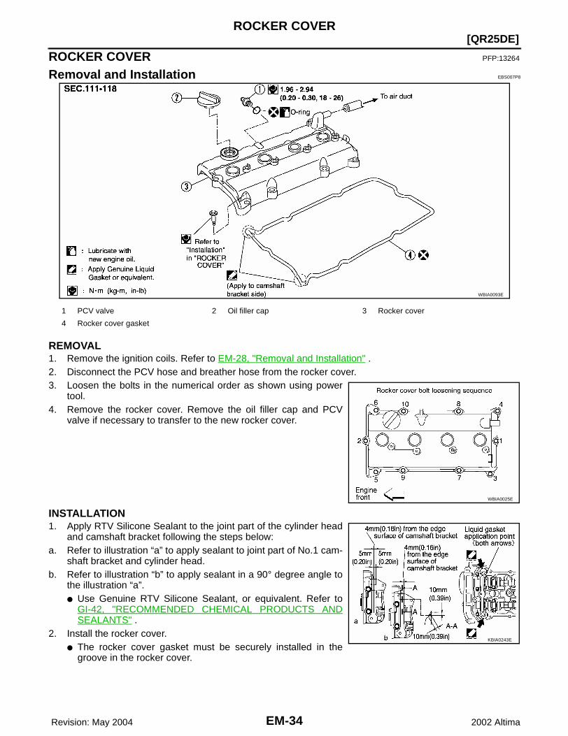
REMOVAL1. Remove the ignition coils. Refer to EM-28, "Removal and Installation" .2. Disconnect the PCV hose and breather hose from the rocker cover.3. Loosen the bolts in the numerical order as shown using power
tool.4. Remove the rocker cover. Remove the oil filler cap and PCV
valve if necessary to transfer to the new rocker cover.
INSTALLATION1. Apply RTV Silicone Sealant to the joint part of the cylinder head
and camshaft bracket following the steps below:a. Refer to illustration “a” to apply sealant to joint part of No.1 cam-
shaft bracket and cylinder head.b. Refer to illustration “b” to apply sealant in a 90° degree angle to
the illustration “a”.● Use Genuine RTV Silicone Sealant, or equivalent. Refer to
GI-42, "RECOMMENDED CHEMICAL PRODUCTS ANDSEALANTS" .
2. Install the rocker cover.● The rocker cover gasket must be securely installed in the
groove in the rocker cover.
WBIA0093E
1 PCV valve 2 Oil filler cap 3 Rocker cover
4 Rocker cover gasket
WBIA0025E
KBIA0243E

ROCKER COVER
EM-35
[QR25DE]
C
D
E
F
G
H
I
J
K
L
M
A
EM
Revision: May 2004 2002 Altima
3. Tighten the rocker cover bolts in two steps, in the numericalorder as shown.
4. Connect the PCV hose and breather hose to the rocker cover. If necessary, install the oil filler cap andPCV valve and lubricate the PCV valve O-ring with new engine oil.
5. Install the ignition coils. Refer to EM-28, "Removal and Installation" .
1st step : 1.0 - 2.9 N·m (0.1 - 0.3 kg-m, 9 - 26 in-lb)2nd step : 7.4 - 9.3 N·m (0.75 - 0.95 kg-m, 65 - 82 in-lb)
WBIA0071E
EM-36 Revision: May 2004
[QR25DE]CAMSHAFT
2002 Altima
CAMSHAFT PFP:13001
Removal and Installation EBS007P9
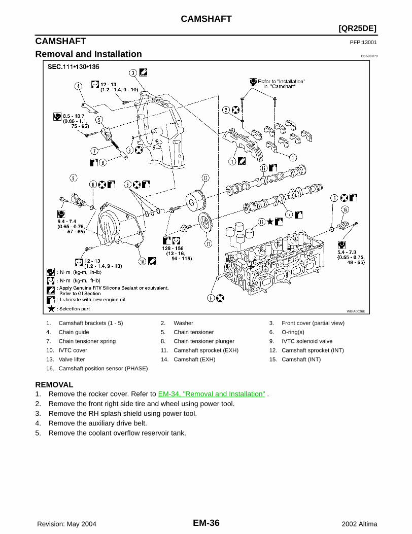
REMOVAL1. Remove the rocker cover. Refer to EM-34, "Removal and Installation" .2. Remove the front right side tire and wheel using power tool.3. Remove the RH splash shield using power tool.4. Remove the auxiliary drive belt.5. Remove the coolant overflow reservoir tank.
WBIA0026E
1. Camshaft brackets (1 - 5) 2. Washer 3. Front cover (partial view)
4. Chain guide 5. Chain tensioner 6. O-ring(s)
7. Chain tensioner spring 8. Chain tensioner plunger 9. IVTC solenoid valve
10. IVTC cover 11. Camshaft sprocket (EXH) 12. Camshaft sprocket (INT)
13. Valve lifter 14. Camshaft (EXH) 15. Camshaft (INT)
16. Camshaft position sensor (PHASE)

CAMSHAFT
EM-37
[QR25DE]
C
D
E
F
G
H
I
J
K
L
M
A
EM
Revision: May 2004 2002 Altima
6. Remove the IVTC (intake valve timing control) cover by cuttingthe sealant using the Tool.● Loosen the bolts in the order shown.
7. Set the No.1 cylinder at TDC on its compression stroke with thefollowing procedure:
a. Open the splash cover on RH under cover.b. Rotate crankshaft pulley clockwise, and align mating marks for
TDC with timing indicator on front cover, as shown.
c. At the same time, make sure that the mating marks on camshaftsprockets are lined up with the yellow links in the timing chain,as shown.● If not, rotate crankshaft pulley one more turn to line up the
mating marks to the yellow links, as shown.
8. Pull the timing chain guide out between the camshaft sprocketsthrough front cover.
WBIA0027E
KBIA0190E
KBIA0115E
KBIA0048E

EM-38 Revision: May 2004
[QR25DE]CAMSHAFT
2002 Altima
9. Remove camshaft sprockets with the following procedure.CAUTION:● Do not rotate the crankshaft or camshaft while the timing
chain is removed. It causes interference between valveand piston.
NOTE:● Chain tension holding work is not necessary. Crank sprocket
and timing chain do not disconnect structurally while frontcover is attached.
a. Line up the mating marks on camshaft sprockets with the yellowlinks in the timing chain, and paint an indelible mating mark onthe sprocket and timing chain link plate.
b. Push in the tensioner plunger and hold. Insert a stopper pin into the hole on tensioner body to hold thechain tensioner. Remove the timing chain tensioner.● Use a wire with 0.5 mm (0.02 in) diameter for a stopper pin.
c. Secure the hexagonal part of camshaft with a suitable tool. Loosen the camshaft sprocket mounting boltsand remove the camshaft sprockets.
10. Loosen the camshaft bracket bolts in the order shown, andremove the camshaft brackets and camshafts.● Remove No.1 camshaft bracket by slightly tapping it with a
rubber mallet. 11. Remove the valve lifters.
● Check mounting positions, and set them aside in the orderremoved.
INSPECTION AFTER REMOVALCamshaft Runout1. Put the camshaft on a V-block supporting the No.2 and No.5
journals.2. Set the dial gauge vertically on the No.3 journal.3. Turn camshaft in one direction by hand, and measure the cam-
shaft runout on the dial gauge total indicator reading.
Camshaft Cam Height1. Measure the camshaft cam height.
2. If wear is beyond the limit, replace the camshaft.
KBIA0049E
WBIA0028E
Standard : Less than 0.04 mm (0.0016 in)
PBIC0038E
Standard intake cam height : 45.665 - 45.855 mm (1.7978 - 1.8053 in)
Standard exhaust cam height : 43.975 - 44.165 mm (1.7313 - 1.7388 in)
PBIC0039E
CAMSHAFT
EM-39
[QR25DE]
C
D
E
F
G
H
I
J
K
L
M
A
EM
Revision: May 2004 2002 Altima
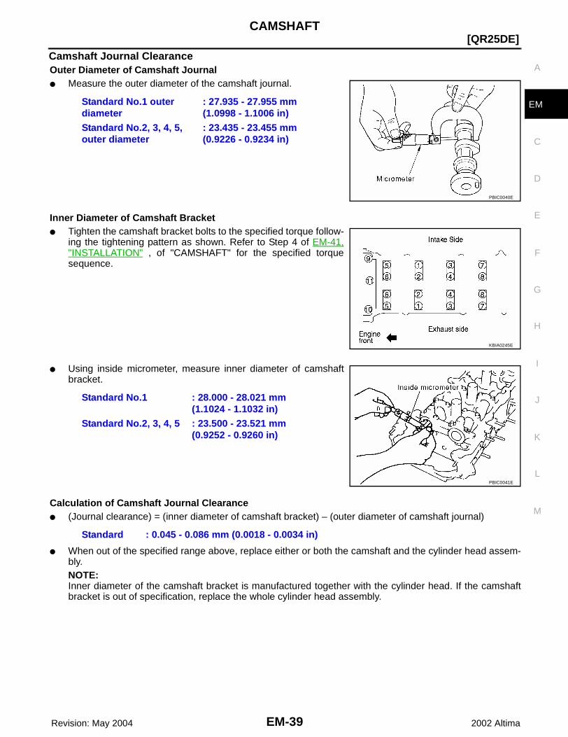
Camshaft Journal ClearanceOuter Diameter of Camshaft Journal● Measure the outer diameter of the camshaft journal.
Inner Diameter of Camshaft Bracket● Tighten the camshaft bracket bolts to the specified torque follow-
ing the tightening pattern as shown. Refer to Step 4 of EM-41,"INSTALLATION" , of "CAMSHAFT" for the specified torquesequence.
● Using inside micrometer, measure inner diameter of camshaftbracket.
Calculation of Camshaft Journal Clearance● (Journal clearance) = (inner diameter of camshaft bracket) – (outer diameter of camshaft journal)
● When out of the specified range above, replace either or both the camshaft and the cylinder head assem-bly.NOTE:Inner diameter of the camshaft bracket is manufactured together with the cylinder head. If the camshaftbracket is out of specification, replace the whole cylinder head assembly.
Standard No.1 outer diameter
: 27.935 - 27.955 mm(1.0998 - 1.1006 in)
Standard No.2, 3, 4, 5, outer diameter
: 23.435 - 23.455 mm(0.9226 - 0.9234 in)
PBIC0040E
KBIA0245E
Standard No.1 : 28.000 - 28.021 mm (1.1024 - 1.1032 in)
Standard No.2, 3, 4, 5 : 23.500 - 23.521 mm (0.9252 - 0.9260 in)
PBIC0041E
Standard : 0.045 - 0.086 mm (0.0018 - 0.0034 in)

EM-40 Revision: May 2004
[QR25DE]CAMSHAFT
2002 Altima
Camshaft End Play1. Install a dial gauge in the thrust direction on the front end of the
camshaft. Measure the end play with the dial gauge while mov-ing the camshaft forward and backward (in direction to axis).
2. If out of the specified range, replace with new camshaft andmeasure again.
3. If out of the specified range again, replace with new cylinderhead assembly.
Camshaft Sprocket Runout1. Install the camshaft in the cylinder head.2. Install the camshaft sprocket on the camshaft.3. Measure camshaft sprocket runout while turning the camshaft
by hand.
4. If it exceeds the specification, replace camshaft sprocket.
Valve Lifter ● Check if the surface of the valve lifter has any excessive wear or
cracks, replace as necessary.
Valve Lifter ClearanceOuter Diameter of Valve Lifter● Measure the outer diameter of the valve lifter.
● If out of the specified range, replace the valve lifter.
Standard end play : 0.115 - 0.188 mm (0.0045 - 0.0074 in)
PBIC0042E
Runout : Less than 0.15 mm (0.0059 in)
KBIA0181J
KBIA0182E
Valve lifter outer diameter : 33.965 - 33.980 mm (1.3372 - 1.3378 in)
JEM798G
CAMSHAFT
EM-41
[QR25DE]
C
D
E
F
G
H
I
J
K
L
M
A
EM
Revision: May 2004 2002 Altima
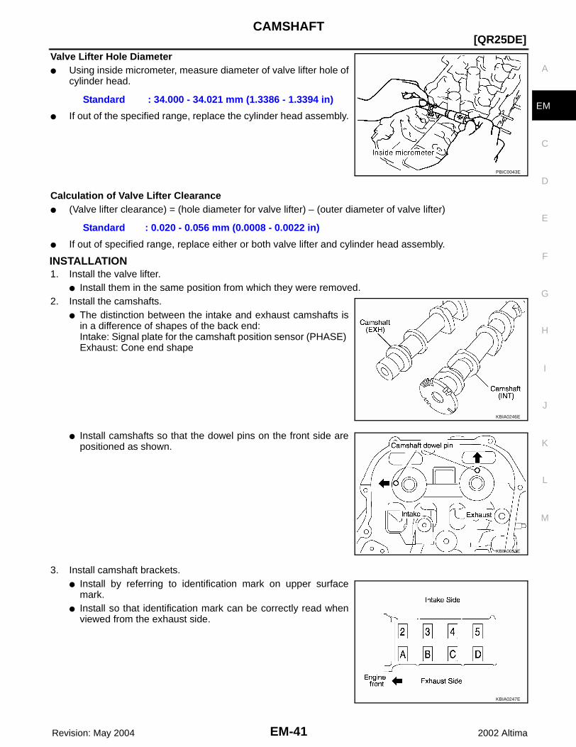
Valve Lifter Hole Diameter● Using inside micrometer, measure diameter of valve lifter hole of
cylinder head.
● If out of the specified range, replace the cylinder head assembly.
Calculation of Valve Lifter Clearance● (Valve lifter clearance) = (hole diameter for valve lifter) – (outer diameter of valve lifter)
● If out of specified range, replace either or both valve lifter and cylinder head assembly.
INSTALLATION1. Install the valve lifter.
● Install them in the same position from which they were removed.2. Install the camshafts.
● The distinction between the intake and exhaust camshafts isin a difference of shapes of the back end:Intake: Signal plate for the camshaft position sensor (PHASE) Exhaust: Cone end shape
● Install camshafts so that the dowel pins on the front side arepositioned as shown.
3. Install camshaft brackets.● Install by referring to identification mark on upper surface
mark.● Install so that identification mark can be correctly read when
viewed from the exhaust side.
Standard : 34.000 - 34.021 mm (1.3386 - 1.3394 in)
PBIC0043E
Standard : 0.020 - 0.056 mm (0.0008 - 0.0022 in)
KBIA0246E
KBIA0051E
KBIA0247E

EM-42 Revision: May 2004
[QR25DE]CAMSHAFT
2002 Altima
● Install No. 1 camshaft bracket as follows.– Apply sealant to No.1 camshaft bracket as shown.● Use Genuine RTV Silicone Sealant, or equivalent. Refer to
GI-42, "RECOMMENDED CHEMICAL PRODUCTS ANDSEALANTS" .CAUTION:● After installation, be sure to wipe off any excessive
sealant leaking from part “A” (both on right and leftsides).
● Apply sealant to camshaft bracket contact surface on the frontcover backside.
● Apply sealant to the outside of bolt hole on front cover.
● Position the No.1 camshaft bracket near the mounting posi-tion, and install it without disturbing the sealant applied to thesurfaces.
4. Tighten fixing bolts of camshaft brackets as follows.a. Tighten in the order from 9 to 11 with tightening torque 2.0 N·m
(0.2 kg-m, 17 in-lb).b. Tighten in the order from 1 to 8 with tightening torque 2.0 N·m
(0.2 kg-m, 17 in-lb).c. Tighten in the order from 1 to 11 with tightening torque 5.9 N·m
(0.6 kg-m, 52 in-lb).d. Tighten in the order from 1 to 11 with tightening torque 9.0 to
11.8 N·m (0.92 to 1.2 kg-m, 80 to 104 in-lb).CAUTION:After tightening fixing bolts of camshaft brackets, be sureto wipe off excessive sealant from the parts listed below: ● Mating surface of rocker cover.● Mating surface of front cover, when installed without the front cover.
KBIA0053E
KBIA0054E
KBIA0118E
KBIA0245E

CAMSHAFT
EM-43
[QR25DE]
C
D
E
F
G
H
I
J
K
L
M
A
EM
Revision: May 2004 2002 Altima
5. Install camshaft sprockets.● Install them by lining up the mating marks on each camshaft
sprocket with the ones painted on the timing chain duringremoval.
● Before installation of chain tensioner, it is possible to re-matchthe marks on timing chain with the ones on each sprocket. CAUTION:● Aligned mating marks could slip. Therefore, after
matching them, hold the timing chain in place by hand.● Before and after installing chain tensioner, check again
to make sure that mating marks have not slipped.6. Install chain tensioner.
CAUTION:● After installation, pull the stopper pin off completely, and make sure that the tensioner is fully
released.7. Install chain guide.8. Install IVTC (intake valve timing control) cover with the following
procedure.a. Install IVTC solenoid valve to intake valve timing control cover.b. Install O-ring to front cover side. c. Apply Genuine RTV Silicone Sealant to the positions shown in
the figure. Refer to GI-42, "RECOMMENDED CHEMICALPRODUCTS AND SEALANTS" .
d. Install IVTC cover.● Tighten the bolts in the numerical order as shown.
9. Check and adjust valve clearances. Refer to EM-43, "ValveClearance" .
10. For the following operations, perform steps in the reverse orderof removal.
Valve Clearance EBS007PA
INSPECTIONNOTE:Perform this inspection as follows after removal, installation, or replacement of the camshaft or any valve-related parts, or if there are any unusual engine conditions due to changes in valve clearance over time (start-ing, idling, and/or noise). 1. Warm up the engine, then stop it.2. Remove front RH engine under cover using power tool. 3. Remove the rocker cover using power tool.
Refer to EM-34, "Removal and Installation" .
KBIA0115E
KBIA0084E
KBIA0085E
EM-44 Revision: May 2004
[QR25DE]CAMSHAFT
2002 Altima
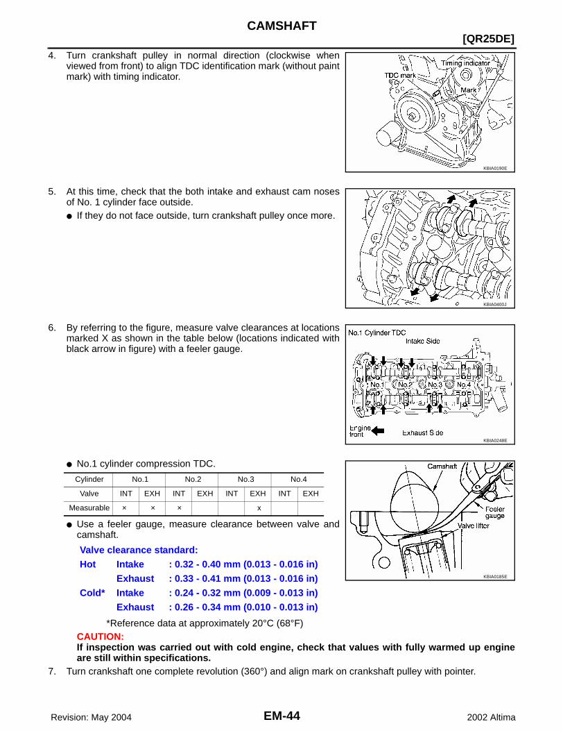
4. Turn crankshaft pulley in normal direction (clockwise whenviewed from front) to align TDC identification mark (without paintmark) with timing indicator.
5. At this time, check that the both intake and exhaust cam nosesof No. 1 cylinder face outside.● If they do not face outside, turn crankshaft pulley once more.
6. By referring to the figure, measure valve clearances at locationsmarked X as shown in the table below (locations indicated withblack arrow in figure) with a feeler gauge.
● No.1 cylinder compression TDC.
● Use a feeler gauge, measure clearance between valve andcamshaft.
*Reference data at approximately 20°C (68°F)CAUTION:If inspection was carried out with cold engine, check that values with fully warmed up engineare still within specifications.
7. Turn crankshaft one complete revolution (360°) and align mark on crankshaft pulley with pointer.
KBIA0190E
KBIA0400J
KBIA0248E
Cylinder No.1 No.2 No.3 No.4
Valve INT EXH INT EXH INT EXH INT EXH
Measurable × × × x
Valve clearance standard:Hot Intake : 0.32 - 0.40 mm (0.013 - 0.016 in)
Exhaust : 0.33 - 0.41 mm (0.013 - 0.016 in)Cold* Intake : 0.24 - 0.32 mm (0.009 - 0.013 in)
Exhaust : 0.26 - 0.34 mm (0.010 - 0.013 in)
KBIA0185E
CAMSHAFT
EM-45
[QR25DE]
C
D
E
F
G
H
I
J
K
L
M
A
EM
Revision: May 2004 2002 Altima
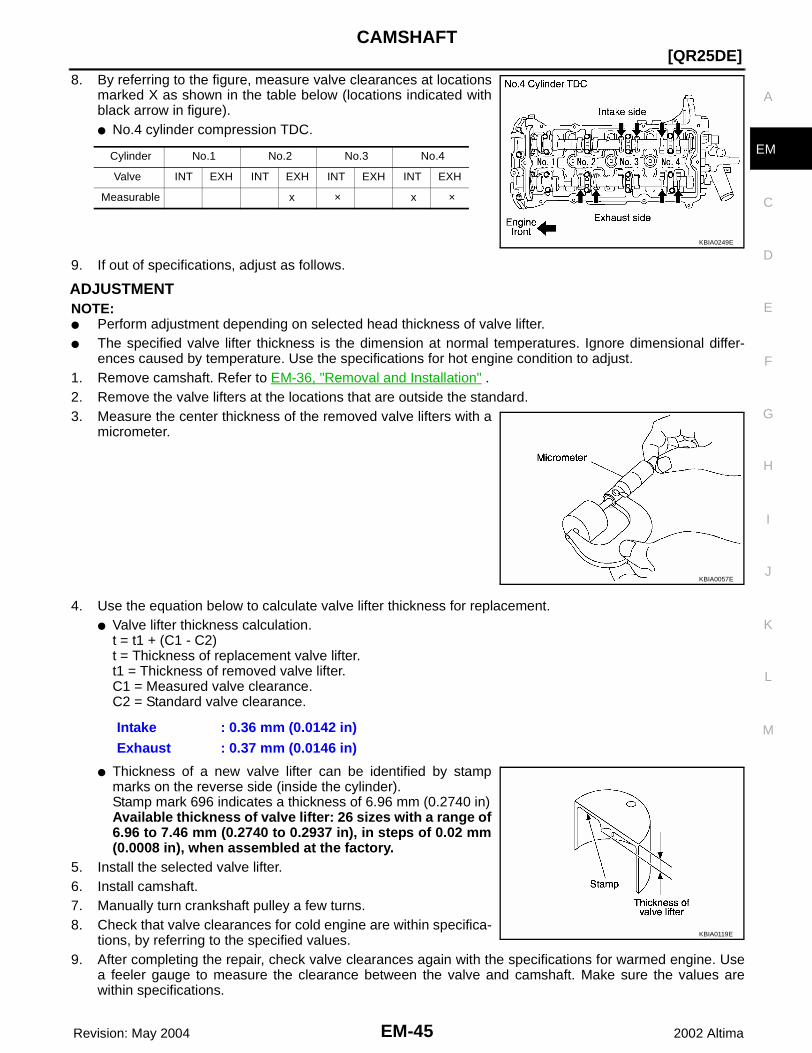
8. By referring to the figure, measure valve clearances at locationsmarked X as shown in the table below (locations indicated withblack arrow in figure). ● No.4 cylinder compression TDC.
9. If out of specifications, adjust as follows.
ADJUSTMENTNOTE:● Perform adjustment depending on selected head thickness of valve lifter.● The specified valve lifter thickness is the dimension at normal temperatures. Ignore dimensional differ-
ences caused by temperature. Use the specifications for hot engine condition to adjust.1. Remove camshaft. Refer to EM-36, "Removal and Installation" .2. Remove the valve lifters at the locations that are outside the standard.3. Measure the center thickness of the removed valve lifters with a
micrometer.
4. Use the equation below to calculate valve lifter thickness for replacement.● Valve lifter thickness calculation.
t = t1 + (C1 - C2)t = Thickness of replacement valve lifter.t1 = Thickness of removed valve lifter.C1 = Measured valve clearance.C2 = Standard valve clearance.
● Thickness of a new valve lifter can be identified by stampmarks on the reverse side (inside the cylinder).Stamp mark 696 indicates a thickness of 6.96 mm (0.2740 in)Available thickness of valve lifter: 26 sizes with a range of6.96 to 7.46 mm (0.2740 to 0.2937 in), in steps of 0.02 mm(0.0008 in), when assembled at the factory.
5. Install the selected valve lifter.6. Install camshaft.7. Manually turn crankshaft pulley a few turns. 8. Check that valve clearances for cold engine are within specifica-
tions, by referring to the specified values.9. After completing the repair, check valve clearances again with the specifications for warmed engine. Use
a feeler gauge to measure the clearance between the valve and camshaft. Make sure the values arewithin specifications.
Cylinder No.1 No.2 No.3 No.4
Valve INT EXH INT EXH INT EXH INT EXH
Measurable x × x ×
KBIA0249E
KBIA0057E
Intake : 0.36 mm (0.0142 in)Exhaust : 0.37 mm (0.0146 in)
KBIA0119E

EM-46 Revision: May 2004
[QR25DE]CAMSHAFT
2002 Altima
Valve ClearanceUnit: mm (in)
*: Reference data at approximately 20°C (68°F)
Valve Cold* (reference data) Hot
Intake 0.24 - 0.32 (0.009 - 0.013) 0.32 - 0.40 (0.013 - 0.016)
Exhaust 0.26 - 0.34 (0.010 - 0.013) 0.33 - 0.41 (0.013 - 0.016)

TIMING CHAIN
EM-47
[QR25DE]
C
D
E
F
G
H
I
J
K
L
M
A
EM
Revision: May 2004 2002 Altima
TIMING CHAIN PFP:13028
Removal and Installation EBS007PB
CAUTION:Apply new engine oil to parts marked in illustration before installation.
WBIA0031E
1. Oil rings 2. Camshaft sprocket (INT) 3. Camshaft sprocket (EXH)
4. Chain tensioner 5. Spring 6. Chain tensioner plunger
7. Timing chain slack guide 8. Timing chain 9. Front cover
10. Chain guide 11. IVTC solenoid valve 12. IVTC cover
13. Engine mounting bracket 14. Crankshaft pulley bolt 15. Crankshaft pulley
16. Front oil seal 17. Balancer unit timing chain tensioner 18. Oil pump drive spacer
19. Crankshaft sprocket 20. Timing chain tension guide 21. Balancer unit timing chain
22. Balancer unit
EM-48 Revision: May 2004
[QR25DE]TIMING CHAIN
2002 Altima
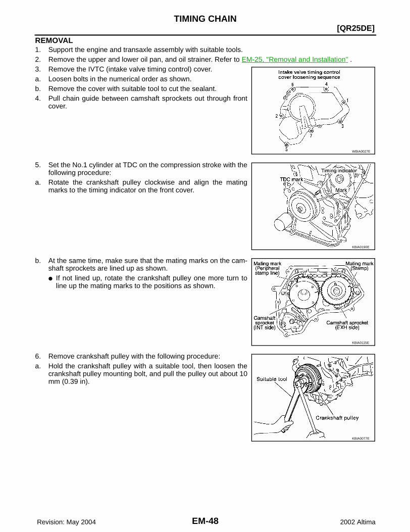
REMOVAL1. Support the engine and transaxle assembly with suitable tools.2. Remove the upper and lower oil pan, and oil strainer. Refer to EM-25, "Removal and Installation" .3. Remove the IVTC (intake valve timing control) cover. a. Loosen bolts in the numerical order as shown. b. Remove the cover with suitable tool to cut the sealant.4. Pull chain guide between camshaft sprockets out through front
cover.
5. Set the No.1 cylinder at TDC on the compression stroke with thefollowing procedure:
a. Rotate the crankshaft pulley clockwise and align the matingmarks to the timing indicator on the front cover.
b. At the same time, make sure that the mating marks on the cam-shaft sprockets are lined up as shown.● If not lined up, rotate the crankshaft pulley one more turn to
line up the mating marks to the positions as shown.
6. Remove crankshaft pulley with the following procedure:a. Hold the crankshaft pulley with a suitable tool, then loosen the
crankshaft pulley mounting bolt, and pull the pulley out about 10mm (0.39 in).
WBIA0027E
KBIA0190E
KBIA0115E
KBIA0077E

TIMING CHAIN
EM-49
[QR25DE]
C
D
E
F
G
H
I
J
K
L
M
A
EM
Revision: May 2004 2002 Altima
b. Attach a pulley puller in the M 6 (0.24 in diameter) thread holeon crankshaft pulley, and remove crankshaft pulley.
7. Remove the front cover with the following procedure:a. Loosen the mounting bolts in the reverse order shown in the fig-
ure, and remove them.b. Remove the front cover.
CAUTION:● Be careful not to damage the mounting surface.
8. If the front oil seal needs to be replaced, lift it out with a screw-driver to remove it.
9. Remove timing chain with the following procedure:a. Push in the tensioner plunger. Insert a stopper pin into the hole
on the tensioner body to hold the chain tensioner.● Use a wire of 0.5 mm (0.02 in) diameter as a stopper pin.
b. Remove the chain tensioner.
c. Secure hexagonal part of the camshaft with a wrench andloosen the camshaft sprocket mounting bolt and remove thecamshaft sprocket for both camshafts.CAUTION:● Do not rotate the crankshaft or camshafts while the tim-
ing chain is removed. It can cause damage to the valveand piston.
KBIA0078E
WBIA0032E
KBIA0048E
KBIA0049E
EM-50 Revision: May 2004
[QR25DE]TIMING CHAIN
2002 Altima
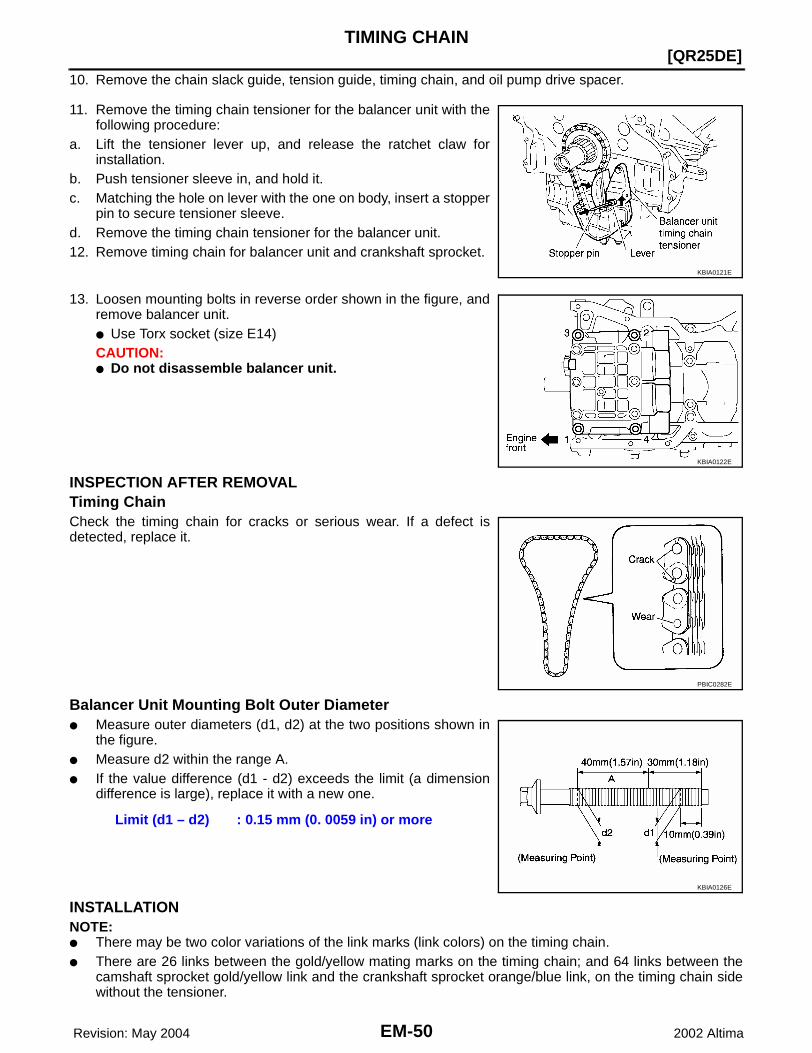
10. Remove the chain slack guide, tension guide, timing chain, and oil pump drive spacer.
11. Remove the timing chain tensioner for the balancer unit with thefollowing procedure:
a. Lift the tensioner lever up, and release the ratchet claw forinstallation.
b. Push tensioner sleeve in, and hold it.c. Matching the hole on lever with the one on body, insert a stopper
pin to secure tensioner sleeve.d. Remove the timing chain tensioner for the balancer unit.12. Remove timing chain for balancer unit and crankshaft sprocket.
13. Loosen mounting bolts in reverse order shown in the figure, andremove balancer unit.● Use Torx socket (size E14)CAUTION:● Do not disassemble balancer unit.
INSPECTION AFTER REMOVALTiming ChainCheck the timing chain for cracks or serious wear. If a defect isdetected, replace it.
Balancer Unit Mounting Bolt Outer Diameter● Measure outer diameters (d1, d2) at the two positions shown in
the figure.● Measure d2 within the range A.● If the value difference (d1 - d2) exceeds the limit (a dimension
difference is large), replace it with a new one.
INSTALLATIONNOTE:● There may be two color variations of the link marks (link colors) on the timing chain. ● There are 26 links between the gold/yellow mating marks on the timing chain; and 64 links between the
camshaft sprocket gold/yellow link and the crankshaft sprocket orange/blue link, on the timing chain sidewithout the tensioner.
KBIA0121E
KBIA0122E
PBIC0282E
Limit (d1 – d2) : 0.15 mm (0. 0059 in) or more
KBIA0126E

TIMING CHAIN
EM-51
[QR25DE]
C
D
E
F
G
H
I
J
K
L
M
A
EM
Revision: May 2004 2002 Altima
1. Make sure the crankshaft key points straight up.2. Install the balancer unit and tighten the mounting bolts in the
numerical order shown with the following procedure:CAUTION:● When reusing a mounting bolt, check its outer diameter
before installation. Refer to EM-50, "Balancer Unit Mount-ing Bolt Outer Diameter" .
a. Apply new engine oil to threads and seating surfaces of mount-ing bolts.
b. Tighten them to 45.2 - 51.0 N·m (4.6 - 5.2 kg-m, 34 - 37 ft-lb).c. Turn them another 90° - 95° degrees (Target: 90° degrees).d. Fully loosen in the reverse order of tightening to 0 N·m (0 kg-m,
0 ft-lb).e. Tighten them to 45.2 - 51.0 N·m (4.6 - 5.2 kg-m, 34 - 37 ft-lb).f. Turn them another 90° - 95° degrees (Target: 90° degrees).
CAUTION:● Check tightening angle with an angle wrench or a pro-
tractor. Do not make judgment by visual check alone.
3. Install the crankshaft sprocket and timing chain for the balancerunit.● Make sure that the crankshaft sprocket is positioned with mat-
ing marks on the block and sprocket meeting at the top.● Install it by lining up mating marks on each sprocket and tim-
ing chain.
4. Install timing chain tensioner for balancer unit.NOTE:Chain guide and tensioner move freely with the caulking pin asthe axle. Therefore, bolt hole position of the three points couldbe changed during removal. If points change, temporarily fix thetwo mounting bolts on the chain guide and move the tensioner tomatch the bolt holes.● Be careful not to let mating marks of each sprocket and timing
chain slip.● After installation, make sure the mating marks have not
slipped, then remove stopper pin and release tensioner.
KBIA0122E
KBIA0080E
KBIA0123E
KBIA0124E

EM-52 Revision: May 2004
[QR25DE]TIMING CHAIN
2002 Altima
5. Install timing chain and related parts.● Install by lining up mating marks on each sprocket and timing
chain as shown.NOTE:Before installing chain tensioner, it is possible to change theposition of mating mark on timing chain for that of each sprocketfor alignment. CAUTION:For the above reason, after the mating marks are aligned,keep them aligned by holding them with a hand. ● Before and after installing chain tensioner, check again to
make sure that mating marks have not slipped.● After installing chain tensioner, remove stopper pin, and make
sure the tensioner moves freely.● To avoid skipped teeth, do not move crankshaft and camshaft
until front cover is installed.
6. Install front oil seal to front cover.● Using a drift of 56 mm (2.20 in) diameter, press oil seal in until
it is flush with front end surface of front cover.CAUTION:Be careful not to cause damage to circumference of oil seal.
7. Install front cover with the following procedure:a. Install O-rings to cylinder head and cylinder block. b. Apply Genuine RTV Silicone Sealant or equivalent, to positions
specified in the figure. Refer to GI-42, "RECOMMENDEDCHEMICAL PRODUCTS AND SEALANTS" .
c. Make sure the mating marks on the timing chain and eachsprocket are still aligned. Then install the front cover.CAUTION:● Be careful not to damage the front oil seal during installa-
tion with the front end of the crankshaft.
KBIA0079E
KBIA0081E
KBIA0082E

TIMING CHAIN
EM-53
[QR25DE]
C
D
E
F
G
H
I
J
K
L
M
A
EM
Revision: May 2004 2002 Altima
d. Tighten mounting bolts in the numerical order shown.e. After all bolts are tightened, retighten them to the specified
torque.
CAUTION:Wipe off any excess sealant leaking at the surface forinstalling the oil pan.
8. Install the chain guide between the camshaft sprockets.9. Install IVTC cover with the following procedure:a. Install IVTC solenoid valves to IVTC cover.b. Install oil rings to the intake camshaft sprocket insertion points on Intake valve timing control backside
cover.c. Install O-ring to front cover.d. Apply RTV Silicone Sealant to the positions in the figure.
e. Tighten the mounting bolts in the numerical order as shown.
10. Insert crankshaft pulley by aligning with crankshaft key. ● Tap its center with a plastic hammer to insert. ● Do not tap the belt hook.
11. Tighten crankshaft pulley mounting bolts.
Front cover bolts : 12 - 13 N·m (1.2 - 1.4 kg-m, 9 - 10 ft-lb)
KBIA0083E
KBIA0084E
KBIA0085E

EM-54 Revision: May 2004
[QR25DE]TIMING CHAIN
2002 Altima
● Secure crankshaft pulley with a pulley holder to tighten the bolt.● Perform angle tightening with the following procedure:
a. Apply new engine oil to threads and seat surfaces of mounting bolts.b. Tighten to initial specifications:·
c. Apply a paint mark on the front cover, mating with any one of sixeasy to recognize stamp marks on bolt flange.
d. Turn crankshaft pulley bolt another 60° to 66° degrees [Target:60° degrees].● Check vertical mounting angle with movement of one stamp
mark.
12. Install the remaining parts in the reverse order of removal.
Crankshaft pulley bolt initial tightening : 37.3 - 47.1 N·m (3.8 - 4.8 kg-m, 28 - 34 ft-lb)
PBIC0258E

CYLINDER HEAD
EM-55
[QR25DE]
C
D
E
F
G
H
I
J
K
L
M
A
EM
Revision: May 2004 2002 Altima
CYLINDER HEAD PFP:11041
On-Vehicle Service EBS007PC
CHECKING COMPRESSION PRESSURE1. Warm up the engine to full operating temperature.2. Release the fuel pressure. Refer to EC-51, "FUEL PRESSURE RELEASE" .3. Remove the ignition coil and spark plug from each cylinder.
Refer to EM-29, "Removal and Installation" .4. Connect engine tachometer (not required in use of CONSULT-ll).5. Disconnect the fuel injector harness connector to avoid any residual fuel injection during the measure-
ment.
6. Install the compression tester with the adapter into the sparkplug hole.
● Use compression gauge whose picking up end inserted tospark plug hole is smaller than 20 mm (0.79 in) in diameter.Otherwise, it may be caught by cylinder head during removal.
7. With the accelerator pedal fully depressed, turn the ignition switch to the “START” position to crank overthe engine. When the gauge pointer stabilizes, read the compression pressure at the specified enginerpm. Perform these steps to check each cylinder.
Engine Compression PressureUnit: kPa (kg/cm2 ) / rpm
CAUTION:Always use a fully charged battery to obtain specified engine cranking speed.● If the engine speed is out of specified rpm range, check the battery. Check engine speed again with a
fully charged battery. ● If compression pressure is below minimum value, check valve clearances and parts associated with
combustion chamber (valve, valve seat, piston, piston ring, cylinder bore, cylinder head, cylinder headgasket). After the checking, measure compression pressure again.
● If some cylinders have low compression pressure, pour small amount of engine oil into the spark plughole of the cylinder to re-check it for compression.
– If the added engine oil improves the compression, the piston rings may be worn or damaged. Check thepiston rings and replace if necessary.
KBIA0130E
SEM387C
Standard Minimum Difference limit between cylinders
1,250 (12.8) / 250 1,060 (10.8) / 250 100 (1.0) / 250

EM-56 Revision: May 2004
[QR25DE]CYLINDER HEAD
2002 Altima
– If the compression pressure remains at low level despite the addition of engine oil, the valves may bemalfunctioning. Check the valves for damage. Replace the valve or valve seat accordingly.
● If two adjacent cylinders have respectively low compression pressure and their compression remainslow even after the addition of engine oil, the head gasket is leaking. In such a case, replace the cylinderhead gasket.
8. Install spark plug, ignition coil and harness connectors.
Removal and Installation EBS007PD
REMOVAL1. Release fuel pressure. Refer to EC-51, "FUEL PRESSURE RELEASE" .2. Remove the hood.3. Drain engine coolant and engine oil.4. Position the RH engine compartment fuse and relay box aside.5. Remove the engine undercovers using power tool.6. Remove the timing chain. Refer to EM-47, "Removal and Installation" .7. Remove the camshafts. Refer to EM-36, "CAMSHAFT" .8. Remove the exhaust manifold using power tool.9. Support the engine from above and underneath with suitable hoist and floor jack.
KBIA0250E
1. Cylinder head assembly 2. Cylinder head gasket 3. Cylinder head bolt
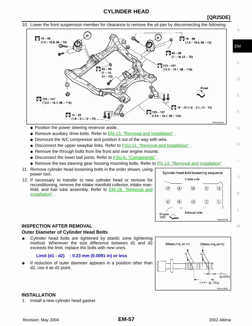
CYLINDER HEAD
EM-57
[QR25DE]
C
D
E
F
G
H
I
J
K
L
M
A
EM
Revision: May 2004 2002 Altima
10. Lower the front suspension member for clearance to remove the oil pan by disconnecting the following:
● Position the power steering reservoir aside.● Remove auxiliary drive belts. Refer to EM-13, "Removal and Installation" .● Dismount the A/C compressor and position it out of the way with wire.● Disconnect the upper swaybar links. Refer to FSU-11, "Removal and Installation" .● Remove the through bolts from the front and rear engine mounts.● Disconnect the lower ball joints. Refer to FSU-5, "Components" .● Remove the two steering gear housing mounting bolts. Refer to PS-13, "Removal and Installation" .
11. Remove cylinder head loosening bolts in the order shown, usingpower tool.
12. If necessary to transfer to new cylinder head or remove forreconditioning, remove the intake manifold collector, intake man-ifold, and fuel tube assembly. Refer to EM-18, "Removal andInstallation" .
INSPECTION AFTER REMOVALOuter Diameter of Cylinder Head Bolts● Cylinder head bolts are tightened by plastic zone tightening
method. Whenever the size difference between d1 and d2exceeds the limit, replace the bolts with new ones.
● If reduction of outer diameter appears in a position other thand2, use it as d2 point.
INSTALLATION1. Install a new cylinder head gasket.
WBIA0034E
WBIA0033E
Limit (d1 - d2) : 0.23 mm (0.0091 in) or less
KBIA0189E
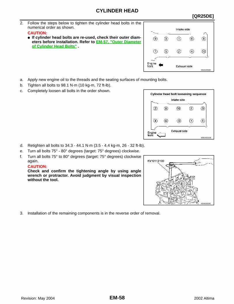
EM-58 Revision: May 2004
[QR25DE]CYLINDER HEAD
2002 Altima
2. Follow the steps below to tighten the cylinder head bolts in thenumerical order as shown.CAUTION:● If cylinder head bolts are re-used, check their outer diam-
eters before installation. Refer to EM-57, "Outer Diameterof Cylinder Head Bolts" .
a. Apply new engine oil to the threads and the seating surfaces of mounting bolts.b. Tighten all bolts to 98.1 N·m (10 kg-m, 72 ft-lb).c. Completely loosen all bolts in the order shown.
d. Retighten all bolts to 34.3 - 44.1 N·m (3.5 - 4.4 kg-m, 26 - 32 ft-lb).e. Turn all bolts 75° - 80° degrees (target: 75° degrees) clockwise.f. Turn all bolts 75° to 80° degrees (target: 75° degrees) clockwise
again.CAUTION:Check and confirm the tightening angle by using anglewrench or protractor. Avoid judgment by visual inspectionwithout the tool.
3. Installation of the remaining components is in the reverse order of removal.
KBIA0058E
WBIA0033E
KBIA0059E
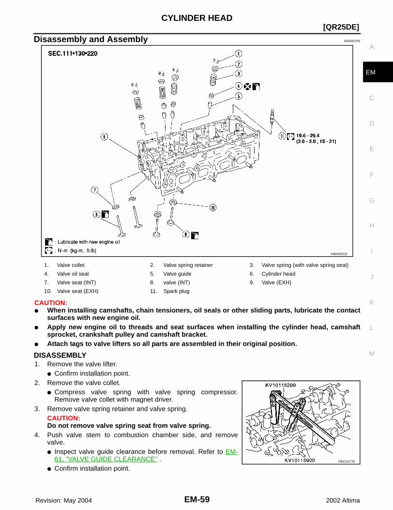
CYLINDER HEAD
EM-59
[QR25DE]
C
D
E
F
G
H
I
J
K
L
M
A
EM
Revision: May 2004 2002 Altima
Disassembly and Assembly EBS007PE
CAUTION:● When installing camshafts, chain tensioners, oil seals or other sliding parts, lubricate the contact
surfaces with new engine oil.● Apply new engine oil to threads and seat surfaces when installing the cylinder head, camshaft
sprocket, crankshaft pulley and camshaft bracket.● Attach tags to valve lifters so all parts are assembled in their original position.
DISASSEMBLY1. Remove the valve lifter.
● Confirm installation point.2. Remove the valve collet.
● Compress valve spring with valve spring compressor.Remove valve collet with magnet driver.
3. Remove valve spring retainer and valve spring.CAUTION:Do not remove valve spring seat from valve spring.
4. Push valve stem to combustion chamber side, and removevalve. ● Inspect valve guide clearance before removal. Refer to EM-
61, "VALVE GUIDE CLEARANCE" .● Confirm installation point.
KBIA0251E
1. Valve collet 2. Valve spring retainer 3. Valve spring (with valve spring seat)
4. Valve oil seal 5. Valve guide 6. Cylinder head
7. Valve seat (INT) 8. valve (INT) 9. Valve (EXH)
10. Valve seat (EXH) 11. Spark plug
PBIC0277E

EM-60 Revision: May 2004
[QR25DE]CYLINDER HEAD
2002 Altima
5. Remove valve oil seal with valve oil seal puller.6. When valve seat must be replaced, refer to EM-63, "VALVE
SEAT REPLACEMENT" .7. When valve guide must be replaced, refer to EM-61, "VALVE
GUIDE REPLACEMENT" .8. Remove spark plug with spark plug wrench.
ASSEMBLY1. Install valve guide. Refer to EM-61, "VALVE GUIDE REPLACEMENT" .2. Install valve seat. Refer to EM-63, "VALVE SEAT REPLACEMENT" .3. Install valve oil seal.
● Install with valve oil seal drift to match dimension in illustra-tion.
4. Install valve.● Install larger diameter to intake side.
5. Install valve spring.● Install smaller pitch (valve spring seat side) to cylinder head
side.● Confirm the identification color of the valve spring:
Intake: blueExhaust: yellow
6. Install valve spring retainer.7. Install valve collet.
● Compress valve spring with valve spring compressor. Installvalve collet with magnet hand.
● Tap stem edge lightly with plastic hammer after installation tocheck its installed condition.
8. Install valve lifter.9. Install spark plug.
Inspection After Disassembly EBS007PF
CYLINDER HEAD DISTORTION1. Wipe off oil and remove water scale deposits, old gasket, old
sealer, and carbon with a scraper.CAUTION:Use care not to allow gasket debris to enter passages for oilor water.
2. At each of several locations on bottom surface of cylinder head,measure distortion in six directions.
SEM093F
KBIA0135E
WBIA0072E
Standard : 0.1 mm (0.004 in) or less
PBIC0075E
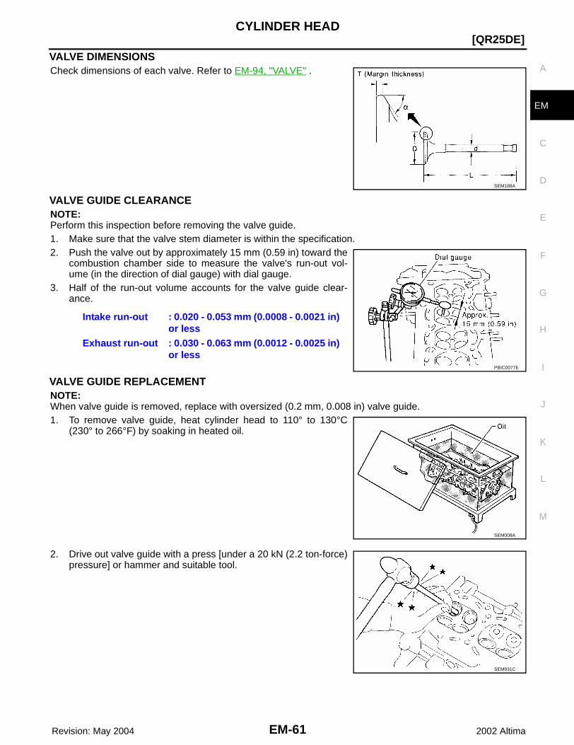
CYLINDER HEAD
EM-61
[QR25DE]
C
D
E
F
G
H
I
J
K
L
M
A
EM
Revision: May 2004 2002 Altima
VALVE DIMENSIONSCheck dimensions of each valve. Refer to EM-94, "VALVE" .
VALVE GUIDE CLEARANCENOTE:Perform this inspection before removing the valve guide.1. Make sure that the valve stem diameter is within the specification.2. Push the valve out by approximately 15 mm (0.59 in) toward the
combustion chamber side to measure the valve's run-out vol-ume (in the direction of dial gauge) with dial gauge.
3. Half of the run-out volume accounts for the valve guide clear-ance.
VALVE GUIDE REPLACEMENTNOTE:When valve guide is removed, replace with oversized (0.2 mm, 0.008 in) valve guide.1. To remove valve guide, heat cylinder head to 110° to 130°C
(230° to 266°F) by soaking in heated oil.
2. Drive out valve guide with a press [under a 20 kN (2.2 ton-force)pressure] or hammer and suitable tool.
SEM188A
Intake run-out : 0.020 - 0.053 mm (0.0008 - 0.0021 in) or less
Exhaust run-out : 0.030 - 0.063 mm (0.0012 - 0.0025 in) or less
PBIC0077E
SEM008A
SEM931C

EM-62 Revision: May 2004
[QR25DE]CYLINDER HEAD
2002 Altima
3. Ream cylinder head valve guide hole.
4. Heat cylinder head to 110° to 130°C (230° to 266°F) by soakingin heated oil.
5. Press valve guide from camshaft side to dimensions as in illus-tration.
6. Using a suitable valve guide reamer, apply the reamer to finishthe valve guide to the specified inner diameter.
VALVE SEAT CONTACTAfter confirming that the dimensions of valve guides and valves arewithin specifications, perform this procedure:● Apply prussian blue (or white lead) onto contacting surface of
valve seat to check the condition of the valve contact on the seatsurface.
● Check if the contact area band is continuous all around the cir-cumference.
● If not, grind to adjust valve fitting and check again. If the contact-ing surface still has N.G. conditions even after the re-check,replace the valve seat.
Valve guide hole diameter for intake and exhaust
: 10.175 - 10.196 mm (0.4006 - 0.4014 in)
SEM932C
SEM008A
PBIC0078E
Intake and exhaust valve guide (inner diameter finished size)
: 6.000 - 6.018 mm (0.2362 - 0.2369 in)
SEM932C
EMA0487D
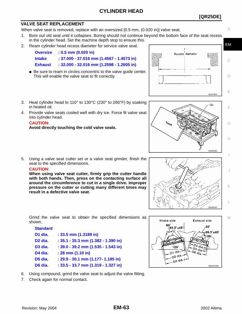
CYLINDER HEAD
EM-63
[QR25DE]
C
D
E
F
G
H
I
J
K
L
M
A
EM
Revision: May 2004 2002 Altima
VALVE SEAT REPLACEMENTWhen valve seat is removed, replace with an oversized [0.5 mm, (0.020 in)] valve seat.1. Bore out old seat until it collapses. Boring should not continue beyond the bottom face of the seat recess
in the cylinder head. Set the machine depth stop to ensure this.2. Ream cylinder head recess diameter for service valve seat.
● Be sure to ream in circles concentric to the valve guide center.This will enable the valve seat to fit correctly.
3. Heat cylinder head to 110° to 130°C (230° to 266°F) by soakingin heated oil.
4. Provide valve seats cooled well with dry ice. Force fit valve seatinto cylinder head.CAUTION:Avoid directly touching the cold valve seats.
5. Using a valve seat cutter set or a valve seat grinder, finish theseat to the specified dimensions.CAUTION:When using valve seat cutter, firmly grip the cutter handlewith both hands. Then, press on the contacting surface allaround the circumference to cut in a single drive. Improperpressure on the cutter or cutting many different times mayresult in a defective valve seat.
Grind the valve seat to obtain the specified dimensions asshown.
6. Using compound, grind the valve seat to adjust the valve fitting. 7. Check again for normal contact.
Oversize : 0.5 mm (0.020 in)Intake : 37.000 - 37.016 mm (1.4567 - 1.4573 in)Exhaust : 32.000 - 32.016 mm (1.2598 - 1.2605 in)
SEM795A
SEM008A
SEM934C
StandardD1 dia. : 33.5 mm (1.3189 in)D2 dia. : 35.1 - 35.3 mm (1.382 - 1.390 in)D3 dia. : 39.0 - 39.2 mm (1.535 - 1.543 in)D4 dia. : 28 mm (1.10 in)D5 dia. : 29.9 - 30.1 mm (1.177- 1.185 in)D6 dia. : 33.5 - 33.7 mm (1.319 - 1.327 in) SBIA0226E
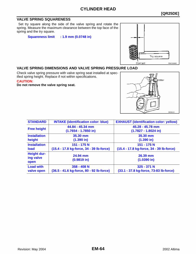
EM-64 Revision: May 2004
[QR25DE]CYLINDER HEAD
2002 Altima
VALVE SPRING SQUARENESS Set try square along the side of the valve spring and rotate thespring. Measure the maximum clearance between the top face of thespring and the try square.
VALVE SPRING DIMENSIONS AND VALVE SPRING PRESSURE LOADCheck valve spring pressure with valve spring seat installed at spec-ified spring height. Replace if not within specifications.CAUTION:Do not remove the valve spring seat.
Squareness limit : 1.9 mm (0.0748 in)
PBIC0080E
SEM113
STANDARD INTAKE (identification color: blue) EXHAUST (identification color: yellow)
Free height44.84 - 45.34 mm
(1.7654 - 1.7850 in)45.28 - 45.78 mm
(1.7827 - 1.8024 in)Installation height
35.30 mm(1.390 in)
35.30 mm(1.390 in)
Installation load
151 - 175 N(15.4 - 17.8 kg-force, 34 - 39 lb-force)
151 - 175 N(15.4 - 17.8 kg-force, 34 - 39 lb-force)
Height dur-ing valve open
24.94 mm(0.9819 in)
26.39 mm(1.0390 in)
Load with valve open
358 - 408 N(36.5 - 41.6 kg-force, 80 - 92 lb-force)
325 - 371 N(33.1 - 37.8 kg-force, 73-83 lb-force)
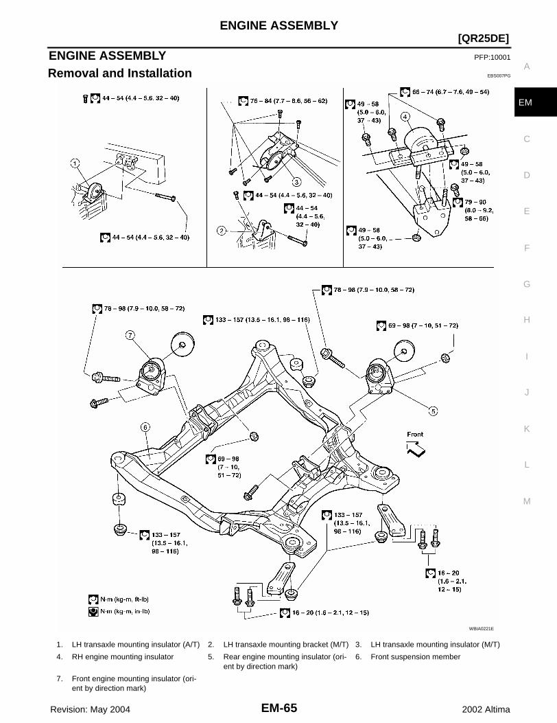
ENGINE ASSEMBLY
EM-65
[QR25DE]
C
D
E
F
G
H
I
J
K
L
M
A
EM
Revision: May 2004 2002 Altima
ENGINE ASSEMBLY PFP:10001
Removal and Installation EBS007PG
WBIA0221E
1. LH transaxle mounting insulator (A/T) 2. LH transaxle mounting bracket (M/T) 3. LH transaxle mounting insulator (M/T)
4. RH engine mounting insulator 5. Rear engine mounting insulator (ori-ent by direction mark)
6. Front suspension member
7. Front engine mounting insulator (ori-ent by direction mark)
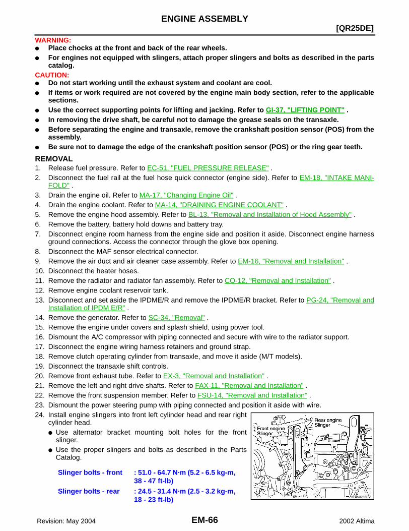
EM-66 Revision: May 2004
[QR25DE]ENGINE ASSEMBLY
2002 Altima
WARNING:● Place chocks at the front and back of the rear wheels.● For engines not equipped with slingers, attach proper slingers and bolts as described in the parts
catalog.CAUTION:● Do not start working until the exhaust system and coolant are cool.● If items or work required are not covered by the engine main body section, refer to the applicable
sections.● Use the correct supporting points for lifting and jacking. Refer to GI-37, "LIFTING POINT" .● In removing the drive shaft, be careful not to damage the grease seals on the transaxle.● Before separating the engine and transaxle, remove the crankshaft position sensor (POS) from the
assembly.● Be sure not to damage the edge of the crankshaft position sensor (POS) or the ring gear teeth.
REMOVAL1. Release fuel pressure. Refer to EC-51, "FUEL PRESSURE RELEASE" . 2. Disconnect the fuel rail at the fuel hose quick connector (engine side). Refer to EM-18, "INTAKE MANI-
FOLD" .3. Drain the engine oil. Refer to MA-17, "Changing Engine Oil" .4. Drain the engine coolant. Refer to MA-14, "DRAINING ENGINE COOLANT" .5. Remove the engine hood assembly. Refer to BL-13, "Removal and Installation of Hood Assembly" .6. Remove the battery, battery hold downs and battery tray.7. Disconnect engine room harness from the engine side and position it aside. Disconnect engine harness
ground connections. Access the connector through the glove box opening. 8. Disconnect the MAF sensor electrical connector. 9. Remove the air duct and air cleaner case assembly. Refer to EM-16, "Removal and Installation" .10. Disconnect the heater hoses.11. Remove the radiator and radiator fan assembly. Refer to CO-12, "Removal and Installation" .12. Remove engine coolant reservoir tank.13. Disconnect and set aside the IPDME/R and remove the IPDME/R bracket. Refer to PG-24, "Removal and
Installation of IPDM E/R" .14. Remove the generator. Refer to SC-34, "Removal" .15. Remove the engine under covers and splash shield, using power tool.16. Dismount the A/C compressor with piping connected and secure with wire to the radiator support.17. Disconnect the engine wiring harness retainers and ground strap.18. Remove clutch operating cylinder from transaxle, and move it aside (M/T models).19. Disconnect the transaxle shift controls.20. Remove front exhaust tube. Refer to EX-3, "Removal and Installation" .21. Remove the left and right drive shafts. Refer to FAX-11, "Removal and Installation" .22. Remove the front suspension member. Refer to FSU-14, "Removal and Installation" .23. Dismount the power steering pump with piping connected and position it aside with wire.24. Install engine slingers into front left cylinder head and rear right
cylinder head.● Use alternator bracket mounting bolt holes for the front
slinger.● Use the proper slingers and bolts as described in the Parts
Catalog.
Slinger bolts - front : 51.0 - 64.7 N·m (5.2 - 6.5 kg-m, 38 - 47 ft-lb)
Slinger bolts - rear : 24.5 - 31.4 N·m (2.5 - 3.2 kg-m, 18 - 23 ft-lb) KBIA0255E
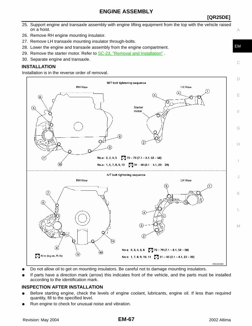
ENGINE ASSEMBLY
EM-67
[QR25DE]
C
D
E
F
G
H
I
J
K
L
M
A
EM
Revision: May 2004 2002 Altima
25. Support engine and transaxle assembly with engine lifting equipment from the top with the vehicle raisedon a hoist.
26. Remove RH engine mounting insulator.27. Remove LH transaxle mounting insulator through-bolts.28. Lower the engine and transaxle assembly from the engine compartment.29. Remove the starter motor. Refer to SC-23, "Removal and Installation" .30. Separate engine and transaxle.
INSTALLATIONInstallation is in the reverse order of removal.
● Do not allow oil to get on mounting insulators. Be careful not to damage mounting insulators.● If parts have a direction mark (arrow) this indicates front of the vehicle, and the parts must be installed
according to the identification mark.
INSPECTION AFTER INSTALLATION● Before starting engine, check the levels of engine coolant, lubricants, engine oil. If less than required
quantity, fill to the specified level.● Run engine to check for unusual noise and vibration.
WBIA0036E

EM-68 Revision: May 2004
[QR25DE]ENGINE ASSEMBLY
2002 Altima
● Warm up engine thoroughly to make sure there is no leakage of coolant, lubricants, oil, fuel, and exhaustgas.
● Bleed air from passages in pipes and tubes of applicable lines.
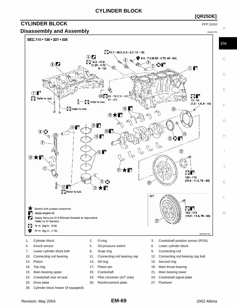
CYLINDER BLOCK
EM-69
[QR25DE]
C
D
E
F
G
H
I
J
K
L
M
A
EM
Revision: May 2004 2002 Altima
CYLINDER BLOCK PFP:11010
Disassembly and Assembly EBS007PH
WBIA0073E
1. Cylinder block 2. O-ring 3. Crankshaft position sensor (POS)
4. Knock sensor 5. Oil pressure switch 6. Lower cylinder block
7. Lower cylinder block bolt 8. Snap ring 9. Connecting rod
10. Connecting rod bearing 11. Connecting rod bearing cap 12. Connecting rod bearing cap bolt
13. Piston 14. Oil ring 15. Second ring
16. Top ring 17. Piston pin 18. Main thrust bearing
19. Main bearing upper 20. Crankshaft 21. Main bearing lower
22. Crankshaft rear oil seal 23. Pilot converter (A/T only) 24. Crankshaft signal plate
25. Drive plate 26. Reinforcement plate 27. Flywheel
28. Cylinder block heater (if equipped)

EM-70 Revision: May 2004
[QR25DE]CYLINDER BLOCK
2002 Altima
CAUTION:Apply new engine oil to parts marked in illustration before installation.
DISASSEMBLY1. Remove the engine and transaxle as an assembly from the vehicle, and separate the transaxle from the
engine. Refer to EM-65, "Removal and Installation" .2. Mount the engine on a suitable engine stand.3. Drain any remaining engine oil and coolant from the engine.4. Remove the following components and associated parts.
● Exhaust manifold and three way catalyst assembly. Refer to EM-23, "Removal and Installation" .● Intake manifold collector. Refer to EM-18, "Removal and Installation" .● Intake manifold and fuel tube assembly. Refer to EM-18, "Removal and Installation" .● Ignition coils. Refer to EM-28, "Removal and Installation" .● Rocker cover. Refer to EM-34, "Removal and Installation" .● Front cover, timing chain, and balancer unit. Refer to EM-47, "Removal and Installation" .● Cylinder head. Refer to EM-56, "Removal and Installation" .
5. Remove the knock sensor.CAUTION:Carefully handle the sensor and do not drop the sensor.
6. Remove crankshaft position sensor (POS).CAUTION:● Avoid impacts such as a dropping.● Do not disassemble.● Keep it away from metal particles.● Do not place sensor close to magnetic materials.
7. Remove the flywheel (M/T models) or drive plate (A/T models)using specified Tool. Hold the crankshaft with a stopper plateand remove the mounting bolts.
CAUTION:Be careful not to damage the flywheel contact surface forthe clutch disc.NOTE:The flywheel two-block construction allows movement inresponse to transmission side pressure, or when twisted in itsrotational direction, therefore, some amount of noise is normal.
8. Remove pilot converter using Tool (A/T models).
KBIA0141E
Flywheel bolt Tool : J-45737Drive plate bolt Tool : J-45816
KBIA0062E
KBIA0188E
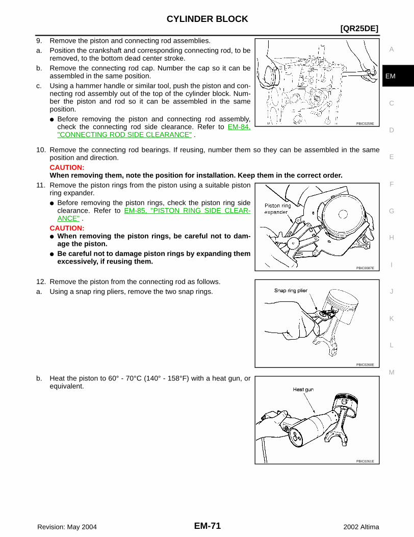
CYLINDER BLOCK
EM-71
[QR25DE]
C
D
E
F
G
H
I
J
K
L
M
A
EM
Revision: May 2004 2002 Altima
9. Remove the piston and connecting rod assemblies.a. Position the crankshaft and corresponding connecting rod, to be
removed, to the bottom dead center stroke. b. Remove the connecting rod cap. Number the cap so it can be
assembled in the same position.c. Using a hammer handle or similar tool, push the piston and con-
necting rod assembly out of the top of the cylinder block. Num-ber the piston and rod so it can be assembled in the sameposition.● Before removing the piston and connecting rod assembly,
check the connecting rod side clearance. Refer to EM-84,"CONNECTING ROD SIDE CLEARANCE" .
10. Remove the connecting rod bearings. If reusing, number them so they can be assembled in the sameposition and direction.CAUTION:When removing them, note the position for installation. Keep them in the correct order.
11. Remove the piston rings from the piston using a suitable pistonring expander. ● Before removing the piston rings, check the piston ring side
clearance. Refer to EM-85, "PISTON RING SIDE CLEAR-ANCE" .
CAUTION:● When removing the piston rings, be careful not to dam-
age the piston.● Be careful not to damage piston rings by expanding them
excessively, if reusing them.
12. Remove the piston from the connecting rod as follows. a. Using a snap ring pliers, remove the two snap rings.
b. Heat the piston to 60° - 70°C (140° - 158°F) with a heat gun, orequivalent.
PBIC0259E
PBIC0087E
PBIC0260E
PBIC0261E
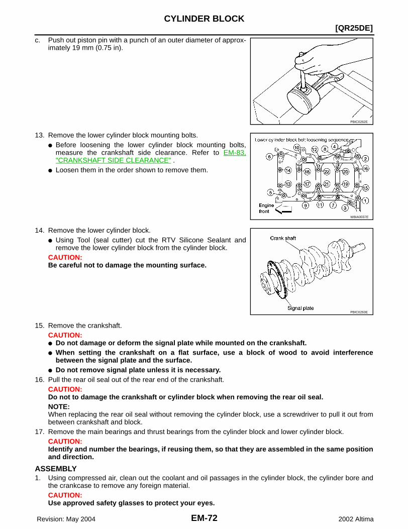
EM-72 Revision: May 2004
[QR25DE]CYLINDER BLOCK
2002 Altima
c. Push out piston pin with a punch of an outer diameter of approx-imately 19 mm (0.75 in).
13. Remove the lower cylinder block mounting bolts.● Before loosening the lower cylinder block mounting bolts,
measure the crankshaft side clearance. Refer to EM-83,"CRANKSHAFT SIDE CLEARANCE" .
● Loosen them in the order shown to remove them.
14. Remove the lower cylinder block.● Using Tool (seal cutter) cut the RTV Silicone Sealant and
remove the lower cylinder block from the cylinder block.CAUTION:Be careful not to damage the mounting surface.
15. Remove the crankshaft.CAUTION:● Do not damage or deform the signal plate while mounted on the crankshaft.● When setting the crankshaft on a flat surface, use a block of wood to avoid interference
between the signal plate and the surface.● Do not remove signal plate unless it is necessary.
16. Pull the rear oil seal out of the rear end of the crankshaft.CAUTION:Do not to damage the crankshaft or cylinder block when removing the rear oil seal.NOTE:When replacing the rear oil seal without removing the cylinder block, use a screwdriver to pull it out frombetween crankshaft and block.
17. Remove the main bearings and thrust bearings from the cylinder block and lower cylinder block.CAUTION:Identify and number the bearings, if reusing them, so that they are assembled in the same positionand direction.
ASSEMBLY1. Using compressed air, clean out the coolant and oil passages in the cylinder block, the cylinder bore and
the crankcase to remove any foreign material.CAUTION:Use approved safety glasses to protect your eyes.
PBIC0262E
WBIA0037E
PBIC0263E

CYLINDER BLOCK
EM-73
[QR25DE]
C
D
E
F
G
H
I
J
K
L
M
A
EM
Revision: May 2004 2002 Altima
2. Install the drain plugs on the cylinder block. ● Apply RTV Silicone Sealant.
Use Genuine RTV Silicone Sealant, or equivalent. Refer toGI-42, "RECOMMENDED CHEMICAL PRODUCTS ANDSEALANTS" .
● Replace the copper washers with new ones.
3. Install the main bearings and the thrust bearings.a. Remove dust, dirt, and oil from the bearing mating surfaces of
the cylinder block and lower cylinder block.b. Install the thrust bearings to both sides of the No. 3 main bearing
journal on the cylinder block.● Install the thrust bearings with the oil groove facing the crank-
shaft arm (outside).
c. Install the main bearings paying attention to their position anddirection.● The main bearing with an oil hole and groove goes on the cyl-
inder block. The one without them goes on the lower cylinderblock.
● Only the main bearing (on the cylinder block) for No. 3 journalhas different specifications.
● Before installing the bearings, apply engine oil to the bearingfriction surface (inside). Do not apply oil to the back surface,but thoroughly clean it.
● When installing, align the bearing stopper to the notch.● Make sure that the oil holes on the cylinder block and those on the corresponding bearing are aligned.
4. Install the signal plate to the crankshaft.
a. Position the crankshaft and signal plate using a positioningdowel pin, and tighten the mounting bolts to specification.
b. Remove the dowel pin.CAUTION:Be sure to remove dowel pin before installing the crank-shaft.NOTE:Dowel pins for the crankshaft and signal plate are supplied as aset for each.
5. Install the crankshaft onto the cylinder block.● While turning the crankshaft by hand, check that it turns smoothly.
KBIA0187E
PBIC0264E
KBIA0142E
Signal plate bolts : 12 - 14 N·m (1.22 - 1.43 kg-m, 9 - 10 ft-lb)
PBIC0265E
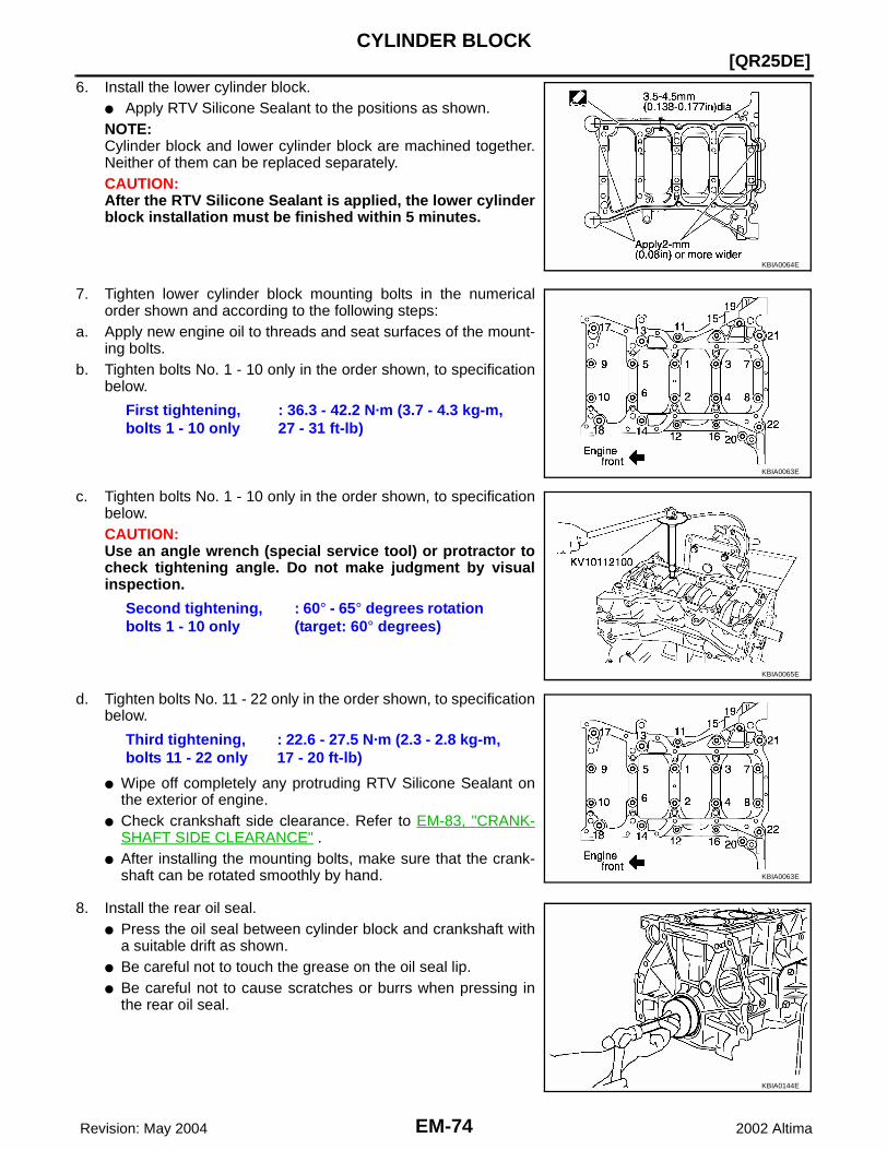
EM-74 Revision: May 2004
[QR25DE]CYLINDER BLOCK
2002 Altima
6. Install the lower cylinder block.● Apply RTV Silicone Sealant to the positions as shown. NOTE:Cylinder block and lower cylinder block are machined together.Neither of them can be replaced separately.CAUTION:After the RTV Silicone Sealant is applied, the lower cylinderblock installation must be finished within 5 minutes.
7. Tighten lower cylinder block mounting bolts in the numericalorder shown and according to the following steps:
a. Apply new engine oil to threads and seat surfaces of the mount-ing bolts.
b. Tighten bolts No. 1 - 10 only in the order shown, to specificationbelow.
c. Tighten bolts No. 1 - 10 only in the order shown, to specificationbelow.CAUTION:Use an angle wrench (special service tool) or protractor tocheck tightening angle. Do not make judgment by visualinspection.
d. Tighten bolts No. 11 - 22 only in the order shown, to specificationbelow.
● Wipe off completely any protruding RTV Silicone Sealant onthe exterior of engine.
● Check crankshaft side clearance. Refer to EM-83, "CRANK-SHAFT SIDE CLEARANCE" .
● After installing the mounting bolts, make sure that the crank-shaft can be rotated smoothly by hand.
8. Install the rear oil seal.● Press the oil seal between cylinder block and crankshaft with
a suitable drift as shown.● Be careful not to touch the grease on the oil seal lip.● Be careful not to cause scratches or burrs when pressing in
the rear oil seal.
KBIA0064E
First tightening, bolts 1 - 10 only
: 36.3 - 42.2 N·m (3.7 - 4.3 kg-m, 27 - 31 ft-lb)
KBIA0063E
Second tightening, bolts 1 - 10 only
: 60° - 65° degrees rotation (target: 60° degrees)
KBIA0065E
Third tightening, bolts 11 - 22 only
: 22.6 - 27.5 N·m (2.3 - 2.8 kg-m, 17 - 20 ft-lb)
KBIA0063E
KBIA0144E
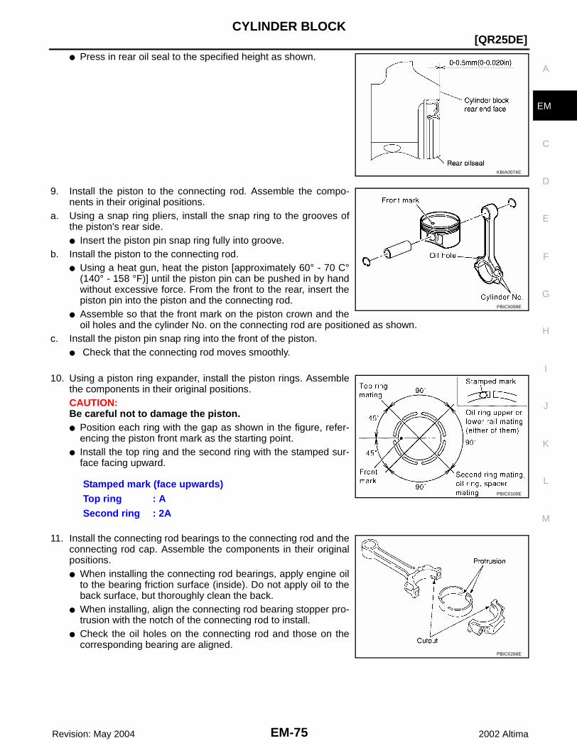
CYLINDER BLOCK
EM-75
[QR25DE]
C
D
E
F
G
H
I
J
K
L
M
A
EM
Revision: May 2004 2002 Altima
● Press in rear oil seal to the specified height as shown.
9. Install the piston to the connecting rod. Assemble the compo-nents in their original positions.
a. Using a snap ring pliers, install the snap ring to the grooves ofthe piston's rear side. ● Insert the piston pin snap ring fully into groove.
b. Install the piston to the connecting rod.● Using a heat gun, heat the piston [approximately 60° - 70 C°
(140° - 158 °F)] until the piston pin can be pushed in by handwithout excessive force. From the front to the rear, insert thepiston pin into the piston and the connecting rod.
● Assemble so that the front mark on the piston crown and theoil holes and the cylinder No. on the connecting rod are positioned as shown.
c. Install the piston pin snap ring into the front of the piston. ● Check that the connecting rod moves smoothly.
10. Using a piston ring expander, install the piston rings. Assemblethe components in their original positions.CAUTION:Be careful not to damage the piston.● Position each ring with the gap as shown in the figure, refer-
encing the piston front mark as the starting point.● Install the top ring and the second ring with the stamped sur-
face facing upward.
11. Install the connecting rod bearings to the connecting rod and theconnecting rod cap. Assemble the components in their originalpositions.● When installing the connecting rod bearings, apply engine oil
to the bearing friction surface (inside). Do not apply oil to theback surface, but thoroughly clean the back.
● When installing, align the connecting rod bearing stopper pro-trusion with the notch of the connecting rod to install.
● Check the oil holes on the connecting rod and those on thecorresponding bearing are aligned.
KBIA0074E
PBIC0099E
Stamped mark (face upwards)Top ring : ASecond ring : 2A
PBIC0100E
PBIC0266E

EM-76 Revision: May 2004
[QR25DE]CYLINDER BLOCK
2002 Altima
12. Install the piston and connecting rod assembly to the crankshaft.Assemble the components in their original positions.● Rotate the crankshaft so the pin corresponding to the con-
necting rod to be installed is at the bottom dead center posi-tion.
● Apply engine oil sufficiently to the cylinder bore, piston, andcrankshaft pin.
● Match the cylinder position number with the cylinder No. onthe connecting rod for installation.
● Using a piston ring compressor, install the piston with the frontmark on the piston crown facing the front of the engine.
CAUTION:Be careful not to damage the crankshaft pin, resulting from an interference of the connecting rodbig end.
13. Install the connecting rod caps. Assemble the components intheir original positions.● Match the stamped cylinder number marks on the connecting
rod with those on the cap to install.
14. Tighten the connecting rod bolt as follows:Apply engine oil to the threads and seats of the connecting rodbolts. CAUTION:Always use either an angle wrench or protractor. Avoidtightening based on visual check alone.
● Check the connecting rod side clearance. Refer to EM-84,"CONNECTING ROD SIDE CLEARANCE" .
● After tightening the bolts, make sure that the crankshaft rotates smoothly.
15. Install flywheel (M/T Models), or drive plate (A/T Models).● Install drive plate, reinforcement plate and pilot converter as
shown in figure.● Using a drift with 33 mm (1.30 in) diameter, push pilot con-
verter into the end of the crankshaft.
PBIC0267E
KBIA0067E
Stage 1 : 18.6 - 20.6 N·m (1.9 - 2.1 kg-m, 14 - 15 ft-lb)Stage 2 : Rotate bolts 85° - 95° degrees (target 90°
degrees)
KBIA0068E
KBIA0075E

CYLINDER BLOCK
EM-77
[QR25DE]
C
D
E
F
G
H
I
J
K
L
M
A
EM
Revision: May 2004 2002 Altima
16. Install the knock sensor.● Make sure that there is no foreign material on the cylinder
block mating surface and the back surface of the knock sen-sor.
● Install the knock sensor with the connector facing lower left by45° as shown.
● Do not tighten the mounting bolts while holding the connector. ● Make sure that the knock sensor does not interfere with other
parts.
CAUTION:If the knock sensor is dropped, replace it with new one.
17. Install the crankshaft position sensor (POS).
18. Remaining installation is in the reverse order of removal.
How to Select Piston and Bearing EBS007PI
DESCRIPTION
*For the service parts, the grade for fitting cannot be selected between a piston pin and a connecting rod.(Only 0 grade is available.) The information at the shipment from the plant is described as a reference. ● The identification grade stamped on each part is the grade for the dimension measured in new condition.
This grade cannot apply to reused parts. ● For reused or repaired parts, measure the dimension accurately. Determine the grade by comparing the
measurement with the values of each selection table.● For details of the measurement method of each part, the reuse standards, and the selection method of the
selective fitting parts, refer to the text.
Knock sensor bolt : 15.7 - 26.5 N·m (1.6 - 2.7 kg-m, 12 - 19 ft-lb)
Crankshaft position sensor bolt : 5.4 - 7.3 N·m (0.55 - 0.75 kg-m, 48 - 65 in-lb)
KBIA0069E
Selection points Selection parts Selection items Selection methods
Between cylinder block to crankshaft
Main bearingMain bearing grade (bearing thickness)
Determined by match of cylin-der block bearing housing grade (inner diameter of hous-ing) and crankshaft journal grade (outer diameter of jour-nal)
Between crankshaft to connect-ing rod
Connecting rod bearingConnecting rod bearing grade (bearing thickness)
Combining service grades for connecting rod big end inner diameter and crankshaft pin outer diameter determine con-necting rod bearing selection
Between cylinder block to pis-ton
Piston and piston pin assembly(The piston is available together with piston pin as an assembly)
Piston grade (piston outer diameter)
Piston grade = cylinder bore grade (inner diameter of bore)
*Between piston to connecting rod
— — —

EM-78 Revision: May 2004
[QR25DE]CYLINDER BLOCK
2002 Altima
HOW TO SELECT A PISTONWhen a New Cylinder Block is Used:● Check the cylinder bore grade on rear left side of cylinder block,
and select a piston of the same grade.
● If there is a corrected stamp mark on the cylinder block, use it asa correct reference.
When a Cylinder Block is Reused:1. Measure the cylinder block bore inner diameter.2. Determine the bore grade by comparing the measurement with the values under the cylinder bore inner
diameter of the "Piston Selection Table". Select the piston of the same grade.
Piston Selection TableUnit: mm (in)
NOTE:● The piston is available together with piston pin as an assembly. ● The piston pin (piston pin bore) grade is provided only for the parts installed at the plant. For service parts,
no grades can be selected. Only 0 grade is available.
HOW TO SELECT A CONNECTING ROD BEARINGWhen New Connecting Rod and Crankshaft are Used:1. Apply big end inside diameter grade stamped on connecting rod
side face to the row in the "Connecting Rod Bearing SelectionTable".
KBIA0070E
WBIA0074E
Grade number (Mark) 1 2 (or no mark) 3
Inner diameter of cylinder bore 89.000-89.010 (3.5039-3.5043) 89.010-89.020 (3.5043-3.5047) 89.020-89.030 (3.5047-3.5051)
Outer diameter of piston 88.980-88.990 (3.5031-3.5035) 88.990-89.000 (3.5035-3.5039) 89.000-89.010 (3.5039-3.5043)
KBIA0067E
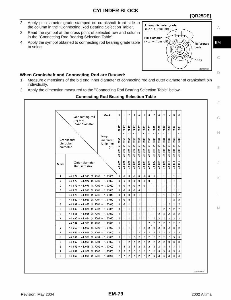
CYLINDER BLOCK
EM-79
[QR25DE]
C
D
E
F
G
H
I
J
K
L
M
A
EM
Revision: May 2004 2002 Altima
2. Apply pin diameter grade stamped on crankshaft front side tothe column in the "Connecting Rod Bearing Selection Table".
3. Read the symbol at the cross point of selected row and columnin the "Connecting Rod Bearing Selection Table".
4. Apply the symbol obtained to connecting rod bearing grade tableto select.
When Crankshaft and Connecting Rod are Reused:1. Measure dimensions of the big end inner diameter of connecting rod and outer diameter of crankshaft pin
individually.2. Apply the dimension measured to the "Connecting Rod Bearing Selection Table" below.
Connecting Rod Bearing Selection Table
KBIA0073E
KBIA0147E

EM-80 Revision: May 2004
[QR25DE]CYLINDER BLOCK
2002 Altima
Connecting Rod Bearing Grade Table
Undersize Bearing Usage Guide● When the specified oil clearance is not obtained with standard size connecting rod bearing, use undersize
(US) bearing.● When using undersize bearing, measure the bearing inner diameter with bearing installed, and grind the
crankshaft pin so that the oil clearance satisfies the standard. Bearing Undersize Table
Unit: mm (in)
CAUTION:In grinding the crankshaft pin to use undersize bearings, do notdamage the fillet R (All crankshaft pins).
HOW TO SELECT A MAIN BEARINGWhen New Cylinder Block and Crankshaft are Used:1. "Main Bearing Selection Table" rows correspond to bearing
housing grade on rear left side of cylinder block.● If there is a corrected stamp mark on the cylinder block, use it
as a correct reference.
2. Apply journal diameter grade stamped on crankshaft front sideto column in "Main Bearing Selection Table".
3. Find value at crossing of row and column in "Main Bearing Selection Table".CAUTION:There are two main bearing selection tables. One is for odd-numbered journals (1, 3, and 5) andthe other is for even-numbered journals (2 and 4). Make certain to use the appropriate table. Thisis due to differences in the specified clearances.
4. Apply the symbol obtained to "Main Bearing Grade Table" to select.NOTE:Service parts are available as a set of both upper and lower.
Grade 0 1 2 3
Upper / Lower thick-ness mm (in)
1.499 / 1.495(0.0590 / 0.0589)
1.503 / 1.499(0.0592 / 0.0590)
1.507 / 1.503(0.0593 / 0.0592)
1.511 / 1.507(0.0595 / 0.0593)
Identification color Black Brown Green Yellow
Size U.S. Thickness
0.25 (0.0098) 1.624 - 1.632 (0.0639 - 0.0643)
KBIA0148E
KBIA0070E
KBIA0073E

CYLINDER BLOCK
EM-81
[QR25DE]
C
D
E
F
G
H
I
J
K
L
M
A
EM
Revision: May 2004 2002 Altima
When Cylinder Block and Crankshaft are Reused:1. Measure inner diameter of cylinder block main bearing housing and outer diameter of crankshaft journal.2. Apply measurement in above step 1 to the "Main Bearing Selection Table".3. Follow steps 3 and 4 in “When New Cylinder Block and Crankshaft are Used”.
Main Bearing Selection Table (No.1, 3, and No.5 journals)
KBIA0149E

EM-82 Revision: May 2004
[QR25DE]CYLINDER BLOCK
2002 Altima
Main Bearing Selection Table (No.2,and 4 journals)
Main Bearing Grade Table (All Journals)Unit: mm (in)
KBIA0150E
Grade number Thickness Identification color
(UPR / LWR)Remarks
0 1.973 - 1.976 (0.0777 - 0.0778) Black
Grade and color are the same for upper and lower bearings.
1 1.976 - 1.979 (0.0778 - 0.0779) Brown
2 1.979 - 1.982 (0.0779- 0.0780) Green
3 1.982 - 1.985 (0.0780 - 0.0781) Yellow
4 1.985 - 1.988 (0.0781 - 0.0783) Blue
5 1.988 - 1.991 (0.0783 - 0.0784) Pink
6 1.991 - 1.994 (0.0784 - 0.0785) Purple
7 1.994 - 1.997 (0.0785 - 0.0786) Orange
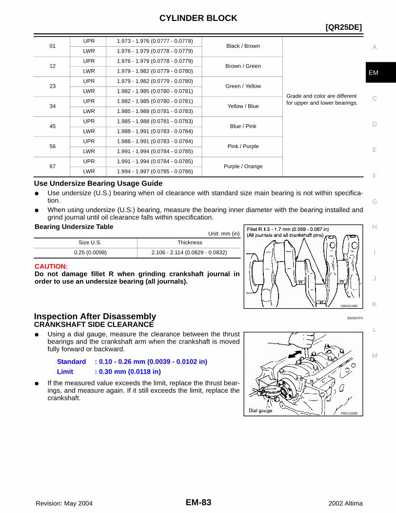
CYLINDER BLOCK
EM-83
[QR25DE]
C
D
E
F
G
H
I
J
K
L
M
A
EM
Revision: May 2004 2002 Altima
Use Undersize Bearing Usage Guide● Use undersize (U.S.) bearing when oil clearance with standard size main bearing is not within specifica-
tion.● When using undersize (U.S.) bearing, measure the bearing inner diameter with the bearing installed and
grind journal until oil clearance falls within specification.Bearing Undersize Table
Unit: mm (in)
CAUTION:Do not damage fillet R when grinding crankshaft journal inorder to use an undersize bearing (all journals).
Inspection After Disassembly EBS007PJ
CRANKSHAFT SIDE CLEARANCE ● Using a dial gauge, measure the clearance between the thrust
bearings and the crankshaft arm when the crankshaft is movedfully forward or backward.
● If the measured value exceeds the limit, replace the thrust bear-ings, and measure again. If it still exceeds the limit, replace thecrankshaft.
01UPR 1.973 - 1.976 (0.0777 - 0.0778)
Black / Brown
Grade and color are different for upper and lower bearings.
LWR 1.976 - 1.979 (0.0778 - 0.0779)
12UPR 1.976 - 1.979 (0.0778 - 0.0779)
Brown / GreenLWR 1.979 - 1.982 (0.0779 - 0.0780)
23UPR 1.979 - 1.982 (0.0779 - 0.0780)
Green / YellowLWR 1.982 - 1.985 (0.0780 - 0.0781)
34UPR 1.982 - 1.985 (0.0780 - 0.0781)
Yellow / BlueLWR 1.985 - 1.988 (0.0781 - 0.0783)
45UPR 1.985 - 1.988 (0.0781 - 0.0783)
Blue / PinkLWR 1.988 - 1.991 (0.0783 - 0.0784)
56UPR 1.988 - 1.991 (0.0783 - 0.0784)
Pink / PurpleLWR 1.991 - 1.994 (0.0784 - 0.0785)
67UPR 1.991 - 1.994 (0.0784 - 0.0785)
Purple / OrangeLWR 1.994 - 1.997 (0.0785 - 0.0786)
Size U.S. Thickness
0.25 (0.0098) 2.106 - 2.114 (0.0829 - 0.0832)
KBIA0148E
Standard : 0.10 - 0.26 mm (0.0039 - 0.0102 in)Limit : 0.30 mm (0.0118 in)
PBIC0268E

EM-84 Revision: May 2004
[QR25DE]CYLINDER BLOCK
2002 Altima
CONNECTING ROD SIDE CLEARANCE● Measure side clearance between connecting rod and crankshaft
arm with feeler gauge.
● If the measured value exceeds the limit, replace the connectingrod bearings, and measure again. If it still exceeds the limit,replace the crankshaft also.
PISTON AND PISTON PIN CLEARANCEInner Diameter of Piston Pin● Measure the inner diameter of piston pin bore with an inside
micrometer.
Outer Diameter of Piston Pin● Measure outer diameter of piston pin with a micrometer.
Piston and Piston Pin Clearance(Piston pin clearance) = (Piston pin bore diameter) – (Outer diameter of piston pin)
● If clearance exceeds specification, replace either or both of pis-ton/piston pin assembly and connecting rod assembly with refer-ence to specification of each parts.
● Refer to piston selection table to replace piston/piston pinassembly. Refer to EM-78, "HOW TO SELECT A PISTON" .
Standard : 0.20 - 0.35 mm (0.0079 - 0.0138 in)Limit : 0.50 mm (0.0197 in)
KBIA0071E
Standard : 19.993 - 20.005 mm (0.7871 - 0.7876 in)
PBIC0116E
Standard : 19.989 - 20.001 mm (0.7870 - 0.7874 in)
PBIC0117E
Standard : 0.002 - 0.006 mm (0.0001 - 0.0002 in)
WBIA0074E
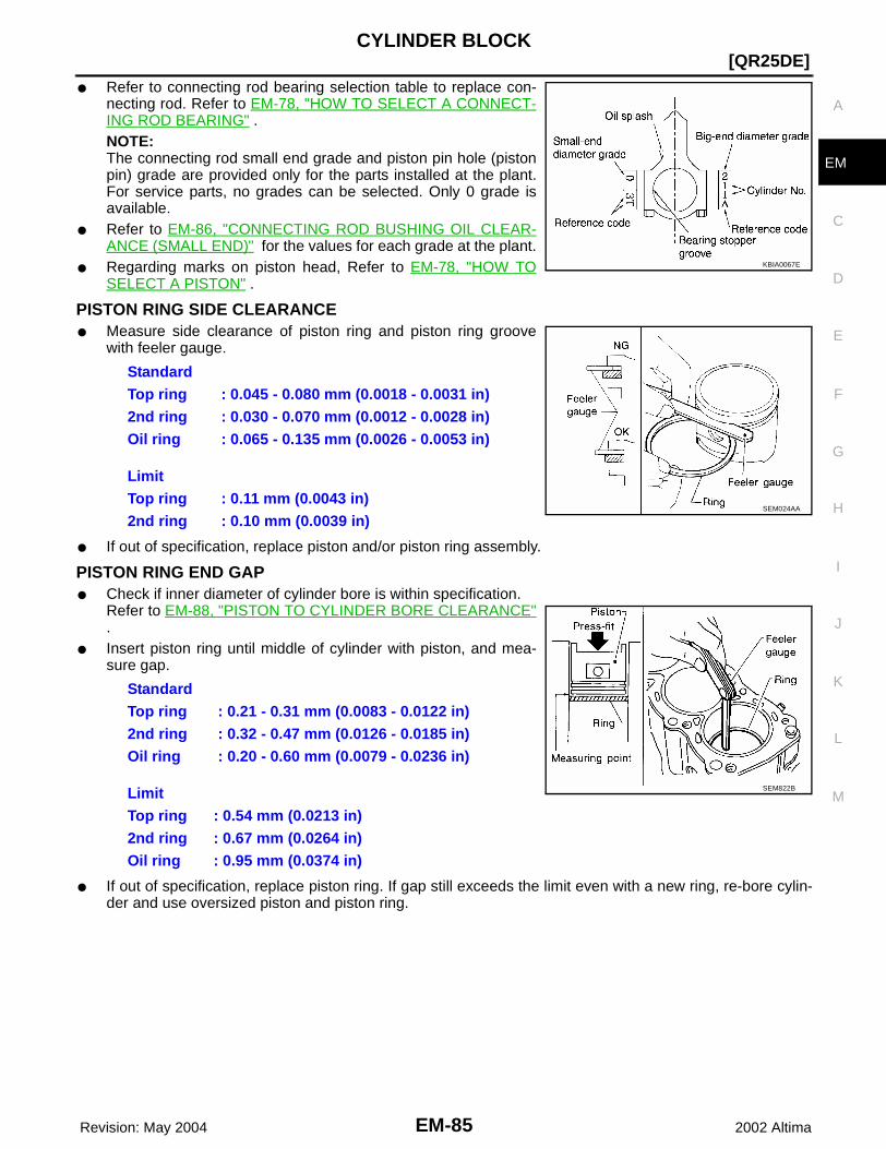
CYLINDER BLOCK
EM-85
[QR25DE]
C
D
E
F
G
H
I
J
K
L
M
A
EM
Revision: May 2004 2002 Altima
● Refer to connecting rod bearing selection table to replace con-necting rod. Refer to EM-78, "HOW TO SELECT A CONNECT-ING ROD BEARING" .NOTE:The connecting rod small end grade and piston pin hole (pistonpin) grade are provided only for the parts installed at the plant.For service parts, no grades can be selected. Only 0 grade isavailable.
● Refer to EM-86, "CONNECTING ROD BUSHING OIL CLEAR-ANCE (SMALL END)" for the values for each grade at the plant.
● Regarding marks on piston head, Refer to EM-78, "HOW TOSELECT A PISTON" .
PISTON RING SIDE CLEARANCE● Measure side clearance of piston ring and piston ring groove
with feeler gauge.
● If out of specification, replace piston and/or piston ring assembly.
PISTON RING END GAP● Check if inner diameter of cylinder bore is within specification.
Refer to EM-88, "PISTON TO CYLINDER BORE CLEARANCE".
● Insert piston ring until middle of cylinder with piston, and mea-sure gap.
● If out of specification, replace piston ring. If gap still exceeds the limit even with a new ring, re-bore cylin-der and use oversized piston and piston ring.
KBIA0067E
StandardTop ring : 0.045 - 0.080 mm (0.0018 - 0.0031 in)2nd ring : 0.030 - 0.070 mm (0.0012 - 0.0028 in)Oil ring : 0.065 - 0.135 mm (0.0026 - 0.0053 in)
LimitTop ring : 0.11 mm (0.0043 in)2nd ring : 0.10 mm (0.0039 in)
SEM024AA
StandardTop ring : 0.21 - 0.31 mm (0.0083 - 0.0122 in)2nd ring : 0.32 - 0.47 mm (0.0126 - 0.0185 in)Oil ring : 0.20 - 0.60 mm (0.0079 - 0.0236 in)
LimitTop ring : 0.54 mm (0.0213 in)2nd ring : 0.67 mm (0.0264 in)Oil ring : 0.95 mm (0.0374 in)
SEM822B

EM-86 Revision: May 2004
[QR25DE]CYLINDER BLOCK
2002 Altima
CONNECTING ROD BEND AND TORSION● Check the connecting rod bend and torsion on the aligner.
● If it exceeds the limit, replace connecting rod assembly.
CONNECTING ROD BEARING (BIG END)● Install the connecting rod cap without the connecting rod bearing
installed. After tightening the connecting rod bolt to the specifiedtorque, measure the connecting rod big end inner diameterusing an inside micrometer.
CONNECTING ROD BUSHING OIL CLEARANCE (SMALL END)Inner Diameter of Connecting Rod (Small End)● Measure inner diameter of bushing.
SEM003F
Bend limit : 0.15 mm (0.0059 in) per 100 mm (3.94 in) length
Torsion limit : 0.30 mm (0.0118 in) per 100 mm (3.94 in) length
SEM038F
Standard : 48.000 - 48.013 mm (1.8898 - 1.8903 in)
PBIC0119E
Standard : 20.000 - 20.012 mm (0.7874 - 0.7879 in)
PBIC0120E

CYLINDER BLOCK
EM-87
[QR25DE]
C
D
E
F
G
H
I
J
K
L
M
A
EM
Revision: May 2004 2002 Altima
Outer Diameter of Piston Pin● Measure outer diameter of piston pin.
Connecting Rod Bushing Oil Clearance (Small End)(Connecting rod small end oil clearance) = (Inner diameter of con-necting rod small end) – (Outer diameter of piston pin)
● If the measured value exceeds the standard, replace the con-necting rod assembly and/or piston and piston pin assembly.
● If replacing the piston and piston pin assembly, refer to the "Pis-ton Selection Table" to select the piston corresponding to theapplicable bore grade of the cylinder block to be used. Refer toEM-78, "HOW TO SELECT A PISTON" .
Factory Installed Parts Grading:NOTE:Service parts apply only to grade 0.
Unit: mm (in)
CYLINDER BLOCK DISTORTION● Using a scraper, remove gasket on the cylinder block surface,
and also remove oil, scale, carbon, or other contamination. CAUTION:Be careful not to allow gasket debris to enter the oil or cool-ant passages.
● Measure the distortion on the block upper face at some differentpoints in 6 directions.
● If out of the distortion limit, replace the cylinder block.
Standard : 19.989 - 20.001 mm (0.7870 - 0.7874 in)
PBIC0117E
Standard : 0.005 - 0.017 mm (0.0002 - 0.0007 in)
KBIA0067E
Grade 0 1
Connecting rod small end inner diameter
20.000 - 20.006 (0.7874 - 0.7876)
20.006 - 20.012 (0.7876 - 0.7879)
Piston pin outer diameter 19.989 - 19.995 (0.7870 - 0.7872)
19.995 - 20. 001 (0.7872 - 0.7874)
Piston pin bore diameter 19.993 - 19.999 (0.7871- 0.7874)
19.999 - 20.005 (0.7874 - 0.7876)
WBIA0074E
Limit : 0.1 mm (0.004 in)PBIC0121E

EM-88 Revision: May 2004
[QR25DE]CYLINDER BLOCK
2002 Altima
INNER DIAMETER OF MAIN BEARING HOUSING● Install the main bearing caps with the main bearings removed
and tighten the mounting bolts to the specified torque. Refer toEM-72, "ASSEMBLY" .
● Using a bore gauge, measure the inner diameter of the mainbearing housing.
● If out of the standard, replace the cylinder block and lower cylin-der block assembly. NOTE:These components cannot be replaced as a single unit becausethey were processed together.
PISTON TO CYLINDER BORE CLEARANCEInner Diameter of Cylinder Bore● Using a bore gauge, measure cylinder bore for wear, out-of-
round and taper at 6 different points on each cylinder. (X and Ydirections at A, B and C). The Y axis is in the longitudinal direc-tion of the engine.NOTE:When determining cylinder bore grade, measure cylinder bore atB position.
● If the measured value rebore exceeds the limit, or if there are scratches and/or seizure on the cylinderinner wall, hone the inner wall.
● An oversize piston is provided. When using an oversize piston, rebore the cylinder so that the clearanceof the piston cylinder satisfies the standard.
Outer Diameter of Piston● Measure piston skirt diameter.
● Measure point (distance from the top): 42 mm (1.65 in)
Piston to Cylinder Bore Clearance● Calculate by outer diameter of piston skirt and inner diameter of cylinder (direction X, position B).
Standard : 58.944 - 58.967 mm (2.3206 - 2.3215 in)PBIC0269E
KBIA0151E
Standard inner diameter: 89.000 - 89.030 mm (3.5039 - 3.5051 in)Wear limit: 0.2 mm (0.008 in)Out-of-round (difference between X – Y): 0.015 mm (0.0006 in)Taper limit (difference between C – A): 0.01 mm (0.0004 in)
Over size (OS) : 0.2 mm (0.008 in)
Standard : 88.980 - 89.010 mm (3.5031 - 3.5043 in)
PBIC0125E

CYLINDER BLOCK
EM-89
[QR25DE]
C
D
E
F
G
H
I
J
K
L
M
A
EM
Revision: May 2004 2002 Altima
(Clearance) = (Inner diameter of cylinder) – (Outer diameter of piston skirt).
● If it exceeds the limit, replace piston/piston pin assembly.
Reboring Cylinder Bore1. Cylinder bore size is determined by adding piston-to-bore clearance to piston diameter “A”.
2. Install main bearing caps, and tighten to the specified torque. Otherwise, cylinder bores may be distortedin final assembly.
3. Cut cylinder bores.● When any cylinder needs boring, all other cylinders must also be bored.● Do not cut too much out of cylinder bore at a time. Cut only 0.05 mm (0.0020 in) or so in diameter at a
time.4. Hone cylinders to obtain specified piston-to-bore clearance.5. Measure finished cylinder bore for out-of-round and taper.
● Measurement should be done after cylinder bore cools down.
OUTER DIAMETER OF CRANKSHAFT JOURNALMeasure outer diameter of crankshaft journals.
OUTER DIAMETER OF CRANKSHAFT PINMeasure outer diameter of crankshaft pin.
OUT-OF-ROUND AND TAPER OF CRANKSHAFT● Using a micrometer, measure the dimensions at four different
points shown in the figure on each journal and pin. ● Out-of-round is indicated by the difference in dimensions
between (X ––Y) at A and B.● Taper is indicated by the difference in dimensions between (A –
B) at X and Y.
Standard : 0.010 - 0.030 mm (0.0004 - 0.0012 in)Limit : 0.08 mm (0.0031 in)
Rebored size calculation: D = A + B - CD : Bored diameterA : Piston diameter as measuredB : Piston-to-bore clearance (standard value)C : Honing allowance 0.02 mm (0.0008 in)
Standard : 54.955 - 54.979 mm (2.1636 - 2.1645 in)
Standard : 44.956 - 44.974 mm (1.7699 - 1.7706 in)
PBIC0270E
LimitOut-of-round (X - Y) : 0.005 mm (0.0002 in)Taper (A - B) : 0.005 mm (0.0002 in)
PBIC0128E

EM-90 Revision: May 2004
[QR25DE]CYLINDER BLOCK
2002 Altima
CRANKSHAFT RUNOUT● Place a V-block on a precise flat table to support the journals on
both ends of the crankshaft.● Place a dial gauge straight up on the No. 3 journal. ● While rotating the crankshaft, read the movement of the pointer
on the dial gauge, the total indicator reading.
OIL CLEARANCE OF CONNECTING ROD BEARINGMethod of Measurement● Install the connecting rod bearings to the connecting rod and the
cap, and tighten the connecting rod bolts to the specified torque.Using a inside micrometer measure the inner diameter of con-necting rod bearing.(Oil clearance) = (Inner diameter of connecting rod bearing) –(Outer diameter of crankshaft pin)
● If clearance cannot be adjusted within the standard, grind crank-shaft pin and use undersized bearing. Refer to EM-78, "HOWTO SELECT A CONNECTING ROD BEARING" .
Method of Using Plastigage● Remove oil and dust on the crankshaft pin and the surfaces of
each bearing completely. ● Cut the Plastigage slightly shorter than the bearing width, and
place it in crankshaft axial direction, avoiding oil holes.● Install the connecting rod bearings to the connecting rod cap,
and tighten the connecting rod bolts to the specified torque. CAUTION:Never rotate the crankshaft.
● Remove the connecting rod cap and bearings, and using thescale on the Plastigage bag, measure the Plastigage width. NOTE:The procedure when the measured value exceeds the limit is same as that described in the method bycalculation.
OIL CLEARANCE OF MAIN BEARINGMethod of Measurement● Install the main bearings to the cylinder block and bearing cap. Measure the main bearing inner diameter
with the bearing cap bolt tightened to the specified torque. (Oil clearance) = (Inner diameter of main bearing) – (Outer diameter of crankshaft journal)
● If the measured value exceeds the limit, select main bearings referring to the main bearing inner diameterand crankshaft journal outer diameter, so that the oil clearance satisfies the standard. Refer to EM-80,"HOW TO SELECT A MAIN BEARING" .
Limit : 0.05 mm (0.002 in)
PBIC0271E
Standard : 0.028 - 0.045 mm (0.0011 - 0.0018 in)Limit : 0.10 mm (0.0039 in)
PBIC0119E
EM142
StandardNo. 1, 3, and 5 journals : 0.012 - 0.022 mm (0.0005 - 0.0009 in)No. 2 and 4 journals : 0.018 - 0.028 mm (0.0007 - 0.0011 in)Limit : 0.1 mm (0.004 in)

CYLINDER BLOCK
EM-91
[QR25DE]
C
D
E
F
G
H
I
J
K
L
M
A
EM
Revision: May 2004 2002 Altima
Method of Using Plastigage● Remove oil and dust on the crankshaft journal and the surfaces
of each bearing completely. ● Cut the Plastigage slightly shorter than the bearing width, and
place it in crankshaft axial direction, avoiding oil holes.● Tighten the main bearing bolts to the specified torque.
CAUTION:Never rotate the crankshaft.
● Remove the bearing cap and bearings, and using the scale onthe plastigage bag, measure the plastigage width. NOTE:The procedure when the measured value exceeds the limit issame as that described in the "Method by Calculation".
CRUSH HEIGHT OF MAIN BEARING● When the bearing cap is removed after being tightened to the
specified torque with main bearings installed, the tip end of bear-ing must protrude.
● If the standard is not met, replace main bearings.
OUTER DIAMETER OF LOWER CYLINDER BLOCK MOUNTING BOLT● Perform only with M10 (0.39 in) bolts.● Measure outer diameters (d1, d2) at two positions as shown.● Measure d2 at a point within block A.● When the value of d1- d2 exceeds the limit (a large difference in
dimensions), replace the bolt with a new one.
OUTER DIAMETER OF CONNECTING ROD BOLT● Measure outer diameter (d) at position shown in the figure.● When “d” exceeds the limit (when it becomes thinner), replace
the bolt with a new one.
EM142
Standard : There must be crush height.
SEM502G
Limit : 0.13 mm (0.0051 in) or more
PBIC0272E
Limit : 7.75 mm (0.3051 in) or less
PBIC0273E

EM-92 Revision: May 2004
[QR25DE]CYLINDER BLOCK
2002 Altima
MOVEMENT AMOUNT OF FLYWHEEL (M/T MODEL)NOTE:● Inspection for double mass flywheel only.● Do not disassemble double mass flywheel.
Flywheel Deflection● Measure deflection of flywheel contact surface to the clutch with a dial gauge.● Measure deflection at 210 mm (8.27 in) dia.
● When measured value exceeds the limit, replace the flywheelwith a new one.
Movement Amount in Radial (Rotation) Direction1. Install a bolt to clutch cover mounting hole, and place a torque wrench on the extended line of the flywheel
center line.● Tighten bolt to keep it from loosening at a force of 9.8 N·m (1 kg-m, 87 in-lb).
2. Put a mating mark on circumferences of the two flywheel masses without applying any load (measure-ment standard points).
3. Apply a force of 9.8 N·m (1 kg-m, 87 in-lb) in each direction, andmark the movement amount on the mass on the transmissionside.
4. Measure the dimensions of movement amounts "A" and "B" onthe circumference of the flywheel on the transmission side.
● When the measured value is outside the standard, replacethe flywheel.
Standard : 0.45 mm (0.0177 in) or lessLimit : 1.3 mm (0.051 in) or less
PBIC0274E
Standard : 28.3 mm (1.114 in) or less
KBIA0297E
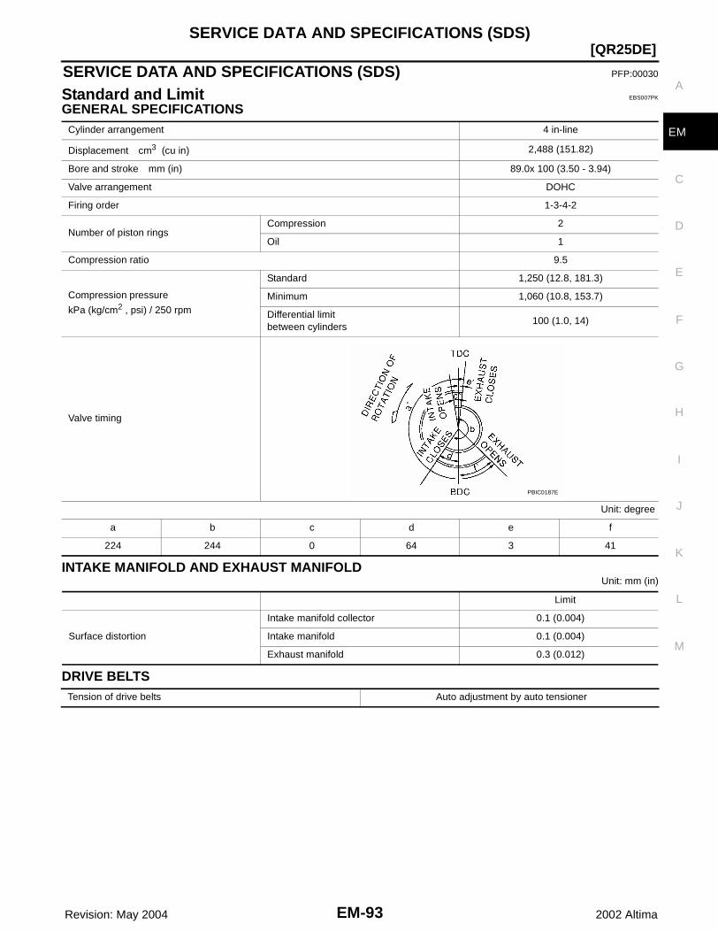
SERVICE DATA AND SPECIFICATIONS (SDS)
EM-93
[QR25DE]
C
D
E
F
G
H
I
J
K
L
M
A
EM
Revision: May 2004 2002 Altima
SERVICE DATA AND SPECIFICATIONS (SDS) PFP:00030
Standard and Limit EBS007PK
GENERAL SPECIFICATIONS
INTAKE MANIFOLD AND EXHAUST MANIFOLDUnit: mm (in)
DRIVE BELTS
Cylinder arrangement 4 in-line
Displacement cm3 (cu in) 2,488 (151.82)
Bore and stroke mm (in) 89.0x 100 (3.50 - 3.94)
Valve arrangement DOHC
Firing order 1-3-4-2
Number of piston ringsCompression 2
Oil 1
Compression ratio 9.5
Compression pressure
kPa (kg/cm2 , psi) / 250 rpm
Standard 1,250 (12.8, 181.3)
Minimum 1,060 (10.8, 153.7)
Differential limit between cylinders
100 (1.0, 14)
Valve timing
Unit: degree
a b c d e f
224 244 0 64 3 41
PBIC0187E
Limit
Surface distortion
Intake manifold collector 0.1 (0.004)
Intake manifold 0.1 (0.004)
Exhaust manifold 0.3 (0.012)
Tension of drive belts Auto adjustment by auto tensioner

EM-94 Revision: May 2004
[QR25DE]SERVICE DATA AND SPECIFICATIONS (SDS)
2002 Altima
CYLINDER HEADUnit: mm (in)
VALVEValve Dimensions
Unit: mm (in)
Valve ClearanceUnit: mm (in)
*: Approximately 20°C (68 °F)
Available Valve Lifter
Limit
Head surface distortion 0.1 (0.004)
PBIC0283E
Valve head diameter “D”Intake 35.5 - 35.8 (1.398 - 1.409)
Exhaust 30.5 - 30.8 (1.201 - 1.213)
Valve length “L”Intake 97.16 (3.8252)
Exhaust 98.82 (3.8905)
Valve stem diameter “d”Intake 5.965 - 5.980 (0.2348 - 0.2354)
Exhaust 5.955 - 5.970 (0.2344 - 0.2350)
Valve seat angle “α”Intake
45°15′ - 45°45′Exhaust
Valve margin “T”Intake 1.1 (0.043)
Exhaust 1.3 (0.051)
SEM188
Cold* (reference data) Hot
Intake 0.24 - 0.32 (0.009 - 0.013) 0.32 - 0.40 (0.013 - 0.016)
Exhaust 0.26 - 0.34 (0.010 - 0.013) 0.33 - 0.41 (0.013 - 0.016)
Thickness mm (in) Identification mark
6.96 (0.2740) 696
6.98 (0.2748) 698
7.00 (0.2756) 700
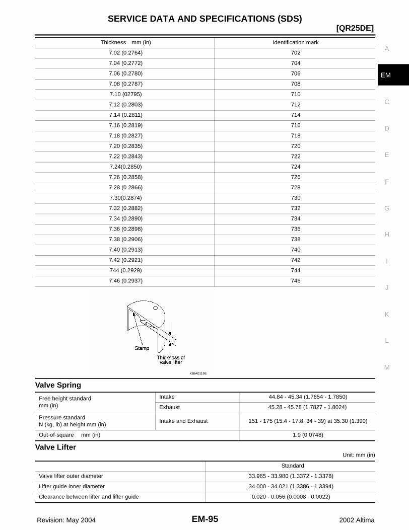
SERVICE DATA AND SPECIFICATIONS (SDS)
EM-95
[QR25DE]
C
D
E
F
G
H
I
J
K
L
M
A
EM
Revision: May 2004 2002 Altima
Valve Spring
Valve LifterUnit: mm (in)
7.02 (0.2764) 702
7.04 (0.2772) 704
7.06 (0.2780) 706
7.08 (0.2787) 708
7.10 (02795) 710
7.12 (0.2803) 712
7.14 (0.2811) 714
7.16 (0.2819) 716
7.18 (0.2827) 718
7.20 (0.2835) 720
7.22 (0.2843) 722
7.24(0.2850) 724
7.26 (0.2858) 726
7.28 (0.2866) 728
7.30(0.2874) 730
7.32 (0.2882) 732
7.34 (0.2890) 734
7.36 (0.2898) 736
7.38 (0.2906) 738
7.40 (0.2913) 740
7.42 (0.2921) 742
744 (0.2929) 744
7.46 (0.2937) 746
Thickness mm (in) Identification mark
KBIA0119E
Free height standardmm (in)
Intake 44.84 - 45.34 (1.7654 - 1.7850)
Exhaust 45.28 - 45.78 (1.7827 - 1.8024)
Pressure standardN (kg, lb) at height mm (in)
Intake and Exhaust 151 - 175 (15.4 - 17.8, 34 - 39) at 35.30 (1.390)
Out-of-square mm (in) 1.9 (0.0748)
Standard
Valve lifter outer diameter 33.965 - 33.980 (1.3372 - 1.3378)
Lifter guide inner diameter 34.000 - 34.021 (1.3386 - 1.3394)
Clearance between lifter and lifter guide 0.020 - 0.056 (0.0008 - 0.0022)
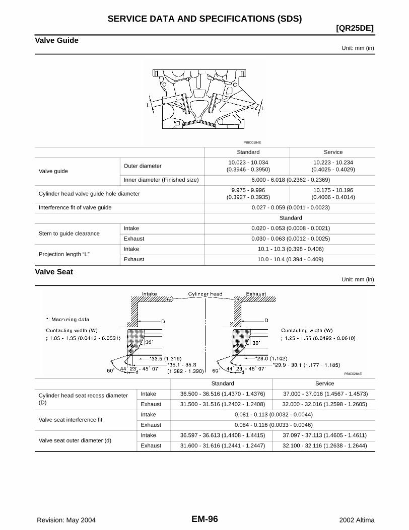
EM-96 Revision: May 2004
[QR25DE]SERVICE DATA AND SPECIFICATIONS (SDS)
2002 Altima
Valve GuideUnit: mm (in)
Valve SeatUnit: mm (in)
Standard Service
Valve guideOuter diameter
10.023 - 10.034(0.3946 - 0.3950)
10.223 - 10.234(0.4025 - 0.4029)
Inner diameter (Finished size) 6.000 - 6.018 (0.2362 - 0.2369)
Cylinder head valve guide hole diameter9.975 - 9.996
(0.3927 - 0.3935)10.175 - 10.196
(0.4006 - 0.4014)
Interference fit of valve guide 0.027 - 0.059 (0.0011 - 0.0023)
Standard
Stem to guide clearanceIntake 0.020 - 0.053 (0.0008 - 0.0021)
Exhaust 0.030 - 0.063 (0.0012 - 0.0025)
Projection length “L”Intake 10.1 - 10.3 (0.398 - 0.406)
Exhaust 10.0 - 10.4 (0.394 - 0.409)
PBIC0184E
Standard Service
Cylinder head seat recess diameter (D)
Intake 36.500 - 36.516 (1.4370 - 1.4376) 37.000 - 37.016 (1.4567 - 1.4573)
Exhaust 31.500 - 31.516 (1.2402 - 1.2408) 32.000 - 32.016 (1.2598 - 1.2605)
Valve seat interference fitIntake 0.081 - 0.113 (0.0032 - 0.0044)
Exhaust 0.084 - 0.116 (0.0033 - 0.0046)
Valve seat outer diameter (d)Intake 36.597 - 36.613 (1.4408 - 1.4415) 37.097 - 37.113 (1.4605 - 1.4611)
Exhaust 31.600 - 31.616 (1.2441 - 1.2447) 32.100 - 32.116 (1.2638 - 1.2644)
PBIC0284E

SERVICE DATA AND SPECIFICATIONS (SDS)
EM-97
[QR25DE]
C
D
E
F
G
H
I
J
K
L
M
A
EM
Revision: May 2004 2002 Altima
CAMSHAFT AND CAMSHAFT BEARINGUnit: mm (in)
*: Total indicator reading
CYLINDER BLOCKUnit: mm (in)
Standard
Camshaft runout [TIR*] Less than 0.04 (0.0016)
Cam height “A”Intake 45.665 - 45.855 (1.7978 - 1.8053)
Exhaust 43.975 - 44.165 (1.7313 - 1.7388)
Outer diameter of camshaft journal
No. 1 27.935 - 27.955 (1.0998 - 1.1006) No. 2, 3, 4, 5 23.435 - 23.455 (0.9226 - 0.9234)
Inner diameter of camshaft bracket
No.1 28.000 - 28.021 (1.1024 - 1.1032) No.2, 3, 4, 5 23.500 - 23.521 (0.9252 - 0.9260)
Camshaft journal clearance 0.045 - 0.086 (0.0018 - 0.0034)
Camshaft end play 0.115 - 0.188 (0.0045 - 0.0074)
Camshaft sprocket runout [TIR*] Less than 0.15 (0.0059)
SEM671
Surface flatness Limit 0.1 (0.004)
Cylinder bore Inner diameterStandard
Grade No. 1 89.000 - 89.010 (3.5039 - 3.5043)
Grade No. 2 89.010 - 89.020 (3.5043 - 3.5047)
Grade No. 3 89.020 - 89.030 (3.5047 - 3.5051)
Wear limit 0.2 (0.008)
Out-of-round (X − Y) Less than 0.015 (0.0006)
Taper (C − A) Less than 0.01 (0.0004)
PBIC0281E

EM-98 Revision: May 2004
[QR25DE]SERVICE DATA AND SPECIFICATIONS (SDS)
2002 Altima
PISTON, PISTON RING, AND PISTON PINAvailable Piston
Unit: mm (in)
Main journal inner diameter grade(Without bearing)
Grade No. AGrade No. BGrade No. CGrade No. DGrade No. EGrade No. FGrade No. GGrade No. HGrade No. JGrade No. KGrade No. LGrade No. MGrade No. NGrade No. PGrade No. RGrade No. SGrade No. TGrade No. UGrade No. VGrade No. WGrade No. XGrade No. YGrade No. 4Grade No. 7
58.944 - 58.945 (2.3206 - 2.3207)58.945 - 58.946 (2.3207 - 2.3207)58.946 - 58.947 (2.3207 - 2.3207)58.947 - 58.948 (2.3207 - 2.3208)58.948 - 58.949 (2.3208 - 2.3208)58.949 - 58.950 (2.3208 - 2.3209)58.950 - 58.951 (2.3209 - 2.3209)58.951 - 58.952 (2.3209 - 2.3209)58.952 - 58.953 (2.3209 - 2.3210)58.953 - 58.954 (2.3210 - 2.3210)58.954 - 58.955 (2.3210 - 2.3211)58.955 - 58.956 (2.3211 - 2.3211)58.956 - 58.957 (2.3211 - 2.3211)58.957 - 58.958 (2.3211 - 2.3212)58.958 - 58.959 (2.3212 - 2.3212)58.959 - 58.960 (2.3212 - 2.3213)58.960 - 58.961 (2.3213 - 2.3213)58.961 - 58.962 (2.3213 - 2.3213)58.962 - 58.963 (2.3213 - 2.3214)58.963 - 58.964 (2.3214 - 2.3214)58.964 - 58.965 (2.3214 - 2.3215)58.965 - 58.966 (2.3215 - 2.3215)58.966 - 58.967 (2.3215 - 2.3215)58.967 - 58.968 (2.3215 - 2.3216)
Difference in inner diameter between cylinders
Standard Less than 0.03 (0.0012)
Piston skirt diameter “A” Standard
Grade No. 1 88.980 - 88.990 (3.5031 - 3.5035)
Grade No. 2 88.990 - 89.000 (3.5035 - 3.5039)
Grade No. 3 89.000 - 89.010 (3.5039 - 3.5043)
0.20 (0.0079) oversize (ser-vice)
89.180 - 89.210 (3.5110 - 3.5122)
“H” dimension 42 (1.65)
Piston pin bore diameterGrade No. 0 19.993 - 19.999 (0.7871 - 0.7874)
Grade No. 1 19.999 - 20.005 (0.7874 - 0.7876)
Piston clearance to cylinder blockStandard 0.010 - 0.030 (0.0004 - 0.0012)
Limit 0.08 (0.0031)
PBIC0188E

SERVICE DATA AND SPECIFICATIONS (SDS)
EM-99
[QR25DE]
C
D
E
F
G
H
I
J
K
L
M
A
EM
Revision: May 2004 2002 Altima
Piston RingUnit: mm (in)
Piston PinUnit: mm (in)
CONNECTING RODUnit: mm (in)
*: After installing in connecting rod
Standard Limit
Side clearance
Top 0.045 - 0.080 (0.0018 - 0.0031) 0.11 (0.0043)
2nd 0.030 - 0.070 (0.0012 - 0.0028) 0.10 (0.004)
Oil ring 0.065 - 0.135 (0.0026 - 0.0053) —
End gap
Top 0.21- 0.31 (0.0083 - 0.0122) 0.54 (0.0213)
2nd 0.32 - 0.47 (0.0126 - 0.0185) 0.67 (0.0264)
Oil (rail ring) 0.20 - 0.60 (0.0079 - 0.0236) 0.95 (0.0374)
Piston pin outer diameterGrade No.0 19.989 - 19.995 (0.7870 - 0.7872)
Grade No.1 19.995 - 20.001 (0.7872 - 0.7874)
Interference fit of piston pin to piston 0.002 - 0.006 (0.0001 - 0.0002)
Piston pin to connecting rod bushing clear-ance
Standard 0.005 - 0.017 (0.0002 - 0.0007)
Center distance 143.00 - 143.10 (5.63 - 5.63)
Bend [per 100 (3.94)] Limit 0.15 (0.0059)
Torsion [per 100 (3.94)] Limit 0.30 (0.0118)
Connecting rod small end inner diameter 22.000 - 22.012 (0.7874 - 0.7879)
Connecting rod small end inner diameter*
Grade No. 0 20.000 - 20.006 (0.7874 - 0.7876)
Grade No. 1 20.006 - 20.012 (0.7876 - 0.7879)
Connecting rod big end inner diameter 48.000 - 48.013 (1.8898 - 1.8903)
Side clearanceStandard 0.20 - 0.35 (0.0079 - 0.0138)
Limit 0.50 (0.0197)
Connecting rod bearing housing
Grade No. 0Grade No. 1Grade No. 2Grade No. 3Grade No. 4Grade No. 5Grade No. 6Grade No. 7Grade No. 8Grade No. 9Grade No. AGrade No. BGrade No. C
48.000 - 48.001 (1.8898 - 1.8898)48.001 - 48.002 (1.8898 - 1.8898)48.002 - 48.003 (1.8898 - 1.8899)48.003 - 48.004 (1.8899 - 1.8899)48.004 - 48.005 (1.8899 - 1.8899)48.005 - 48.006 (1.8899 - 1.8900)48.006 - 48.007 (1.8900 - 1.8900)48.007 - 48.008 (1.8900 - 1.8901)48.008 - 48.009 (1.8901 - 1.8901)48.009 - 48.010 (1.8901 - 1.8902)48.010 - 48.011 (1.8902 - 1.8902)48.011 - 48.012 (1.8902 - 1.8902)48.012 - 48.013 (1.8902 - 1.8903)
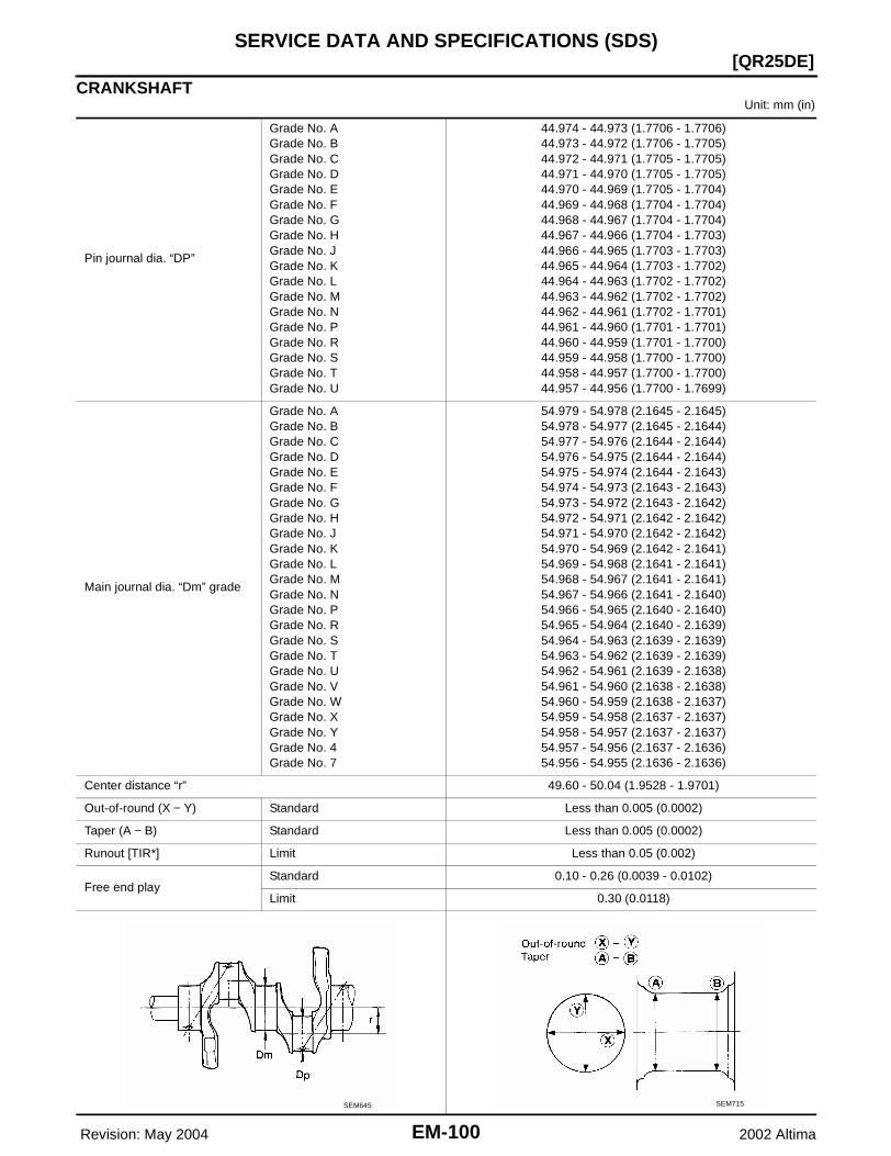
EM-100 Revision: May 2004
[QR25DE]SERVICE DATA AND SPECIFICATIONS (SDS)
2002 Altima
CRANKSHAFTUnit: mm (in)
Pin journal dia. “DP”
Grade No. AGrade No. BGrade No. CGrade No. DGrade No. EGrade No. FGrade No. GGrade No. HGrade No. JGrade No. KGrade No. LGrade No. MGrade No. NGrade No. PGrade No. RGrade No. SGrade No. TGrade No. U
44.974 - 44.973 (1.7706 - 1.7706)44.973 - 44.972 (1.7706 - 1.7705)44.972 - 44.971 (1.7705 - 1.7705)44.971 - 44.970 (1.7705 - 1.7705)44.970 - 44.969 (1.7705 - 1.7704)44.969 - 44.968 (1.7704 - 1.7704)44.968 - 44.967 (1.7704 - 1.7704)44.967 - 44.966 (1.7704 - 1.7703)44.966 - 44.965 (1.7703 - 1.7703)44.965 - 44.964 (1.7703 - 1.7702)44.964 - 44.963 (1.7702 - 1.7702)44.963 - 44.962 (1.7702 - 1.7702)44.962 - 44.961 (1.7702 - 1.7701)44.961 - 44.960 (1.7701 - 1.7701)44.960 - 44.959 (1.7701 - 1.7700)44.959 - 44.958 (1.7700 - 1.7700)44.958 - 44.957 (1.7700 - 1.7700)44.957 - 44.956 (1.7700 - 1.7699)
Main journal dia. “Dm” grade
Grade No. AGrade No. BGrade No. CGrade No. DGrade No. EGrade No. FGrade No. GGrade No. HGrade No. JGrade No. KGrade No. LGrade No. MGrade No. NGrade No. PGrade No. RGrade No. SGrade No. TGrade No. UGrade No. VGrade No. WGrade No. XGrade No. YGrade No. 4Grade No. 7
54.979 - 54.978 (2.1645 - 2.1645)54.978 - 54.977 (2.1645 - 2.1644)54.977 - 54.976 (2.1644 - 2.1644)54.976 - 54.975 (2.1644 - 2.1644)54.975 - 54.974 (2.1644 - 2.1643)54.974 - 54.973 (2.1643 - 2.1643)54.973 - 54.972 (2.1643 - 2.1642)54.972 - 54.971 (2.1642 - 2.1642)54.971 - 54.970 (2.1642 - 2.1642)54.970 - 54.969 (2.1642 - 2.1641)54.969 - 54.968 (2.1641 - 2.1641)54.968 - 54.967 (2.1641 - 2.1641)54.967 - 54.966 (2.1641 - 2.1640)54.966 - 54.965 (2.1640 - 2.1640)54.965 - 54.964 (2.1640 - 2.1639)54.964 - 54.963 (2.1639 - 2.1639)54.963 - 54.962 (2.1639 - 2.1639)54.962 - 54.961 (2.1639 - 2.1638)54.961 - 54.960 (2.1638 - 2.1638)54.960 - 54.959 (2.1638 - 2.1637)54.959 - 54.958 (2.1637 - 2.1637)54.958 - 54.957 (2.1637 - 2.1637)54.957 - 54.956 (2.1637 - 2.1636)54.956 - 54.955 (2.1636 - 2.1636)
Center distance “r” 49.60 - 50.04 (1.9528 - 1.9701)
Out-of-round (X − Y) Standard Less than 0.005 (0.0002)
Taper (A − B) Standard Less than 0.005 (0.0002)
Runout [TIR*] Limit Less than 0.05 (0.002)
Free end playStandard 0.10 - 0.26 (0.0039 - 0.0102)
Limit 0.30 (0.0118)
SEM645 SEM715
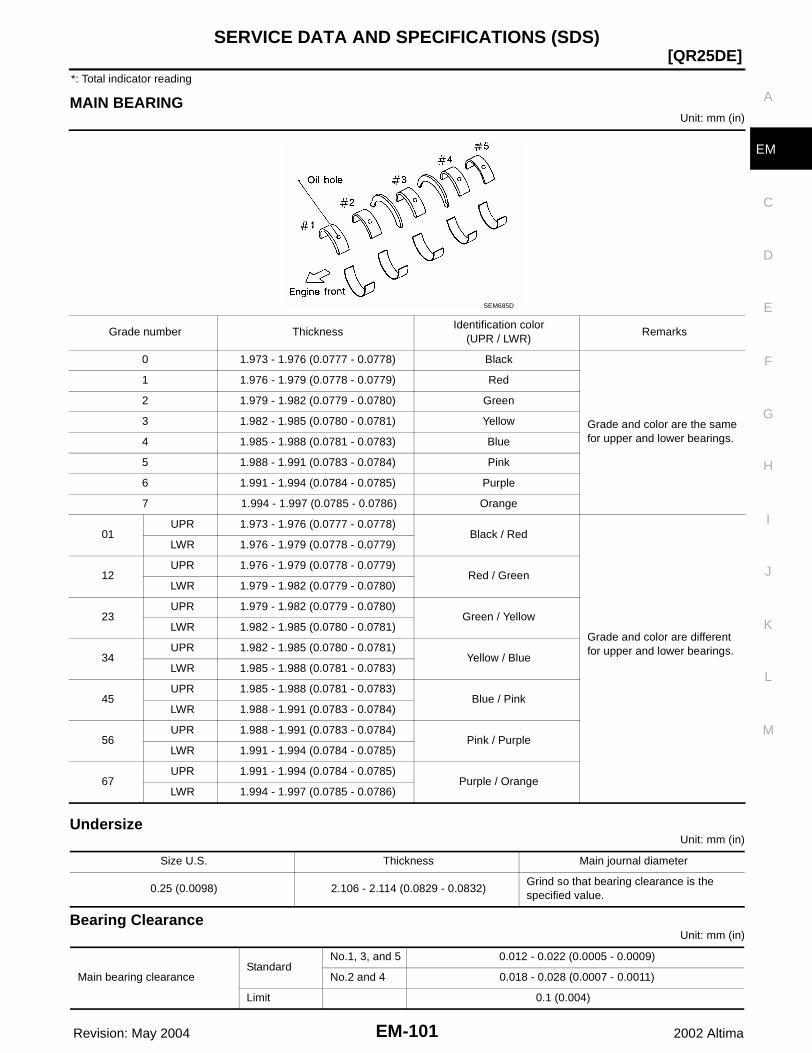
SERVICE DATA AND SPECIFICATIONS (SDS)
EM-101
[QR25DE]
C
D
E
F
G
H
I
J
K
L
M
A
EM
Revision: May 2004 2002 Altima
*: Total indicator reading
MAIN BEARINGUnit: mm (in)
UndersizeUnit: mm (in)
Bearing ClearanceUnit: mm (in)
Grade number Thickness Identification color
(UPR / LWR)Remarks
0 1.973 - 1.976 (0.0777 - 0.0778) Black
Grade and color are the same for upper and lower bearings.
1 1.976 - 1.979 (0.0778 - 0.0779) Red
2 1.979 - 1.982 (0.0779 - 0.0780) Green
3 1.982 - 1.985 (0.0780 - 0.0781) Yellow
4 1.985 - 1.988 (0.0781 - 0.0783) Blue
5 1.988 - 1.991 (0.0783 - 0.0784) Pink
6 1.991 - 1.994 (0.0784 - 0.0785) Purple
7 1.994 - 1.997 (0.0785 - 0.0786) Orange
01UPR 1.973 - 1.976 (0.0777 - 0.0778)
Black / Red
Grade and color are different for upper and lower bearings.
LWR 1.976 - 1.979 (0.0778 - 0.0779)
12UPR 1.976 - 1.979 (0.0778 - 0.0779)
Red / GreenLWR 1.979 - 1.982 (0.0779 - 0.0780)
23UPR 1.979 - 1.982 (0.0779 - 0.0780)
Green / YellowLWR 1.982 - 1.985 (0.0780 - 0.0781)
34UPR 1.982 - 1.985 (0.0780 - 0.0781)
Yellow / BlueLWR 1.985 - 1.988 (0.0781 - 0.0783)
45UPR 1.985 - 1.988 (0.0781 - 0.0783)
Blue / PinkLWR 1.988 - 1.991 (0.0783 - 0.0784)
56UPR 1.988 - 1.991 (0.0783 - 0.0784)
Pink / PurpleLWR 1.991 - 1.994 (0.0784 - 0.0785)
67UPR 1.991 - 1.994 (0.0784 - 0.0785)
Purple / OrangeLWR 1.994 - 1.997 (0.0785 - 0.0786)
SEM685D
Size U.S. Thickness Main journal diameter
0.25 (0.0098) 2.106 - 2.114 (0.0829 - 0.0832)Grind so that bearing clearance is the specified value.
Main bearing clearanceStandard
No.1, 3, and 5 0.012 - 0.022 (0.0005 - 0.0009)
No.2 and 4 0.018 - 0.028 (0.0007 - 0.0011)
Limit 0.1 (0.004)
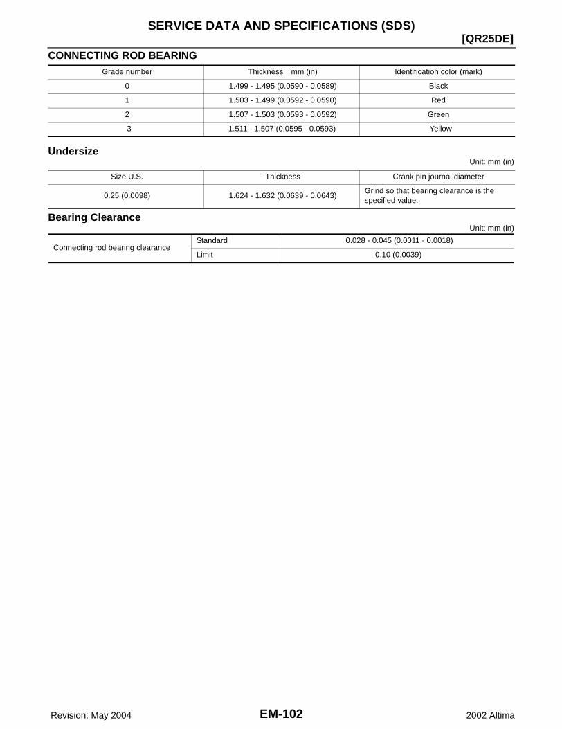
EM-102 Revision: May 2004
[QR25DE]SERVICE DATA AND SPECIFICATIONS (SDS)
2002 Altima
CONNECTING ROD BEARING
UndersizeUnit: mm (in)
Bearing ClearanceUnit: mm (in)
Grade number Thickness mm (in) Identification color (mark)
0 1.499 - 1.495 (0.0590 - 0.0589) Black
1 1.503 - 1.499 (0.0592 - 0.0590) Red
2 1.507 - 1.503 (0.0593 - 0.0592) Green
3 1.511 - 1.507 (0.0595 - 0.0593) Yellow
Size U.S. Thickness Crank pin journal diameter
0.25 (0.0098) 1.624 - 1.632 (0.0639 - 0.0643)Grind so that bearing clearance is the specified value.
Connecting rod bearing clearanceStandard 0.028 - 0.045 (0.0011 - 0.0018)
Limit 0.10 (0.0039)

PRECAUTIONS
EM-103
[VQ35DE]
C
D
E
F
G
H
I
J
K
L
M
A
EM
Revision: May 2004 2002 Altima
PRECAUTIONS PFP:00001
Precautions for Draining Coolant EBS007PL
● Drain coolant when engine is cooled.
Precautions for Disconnecting Fuel Piping EBS007PM
● Before starting work, make sure no fire or spark producing items are in the work area. ● Release fuel pressure before disassembly.● After disconnecting pipes, plug openings to stop fuel leakage.
Precautions for Removal and Disassembly EBS007PN
● When instructed to use special service tools, use the specified tools. Always be careful to work safely,avoid forceful or uninstructed operations.
● Exercise maximum care to avoid damage to mating or sliding surfaces.● Cover openings of engine system with tape or the equivalent, if necessary, to seal out foreign materials.● Mark and arrange disassembly parts in an organized way for easy troubleshooting and assembly.● When loosening nuts and bolts, as a basic rule, start with the one furthest outside, then the one diagonally
opposite, and so on. If the order of loosening is specified, do exactly as specified. Power tools may beused where noted in the step.
Precautions for Inspection, Repair and Replacement EBS007PO
● Before repairing or replacing, thoroughly inspect parts. Inspect new replacement parts in the same way,and replace if necessary.
Precautions for Assembly and Installation EBS007PP
● Use torque wrench to tighten bolts or nuts to specification.● When tightening nuts and bolts, as a basic rule, equally tighten in several different steps starting with the
ones in center, then ones on inside and outside diagonally in this order. If the order of tightening is speci-fied, do exactly as specified.
● Replace with new gasket, packing, oil seal or O-ring.● Thoroughly wash, clean, and air-blow each part. Carefully check oil or coolant passages for any restriction
and blockage. ● Avoid damaging sliding or mating surfaces. Completely remove foreign materials such as cloth lint or dust.
Before assembly, oil sliding surfaces well. ● Release air within route after draining coolant. ● After repairing, start engine and increase engine speed to check coolant, fuel, oil, and exhaust systems
for leakage.
Parts Requiring Angular Tightening EBS007PQ
● Use an angle wrench for the final tightening of the following engine parts: – Cylinder head bolts– Main bearing cap bolts– Connecting rod cap nuts– Crankshaft pulley bolt (No angle wrench is required as the bolt flange is provided with notches for angular
tightening)● Do not use a torque value for final tightening. ● The torque value for these parts are for a preliminary step.● Ensure thread and seat surfaces are clean and coated with engine oil.

EM-104 Revision: May 2004
[VQ35DE]PRECAUTIONS
2002 Altima
Precautions for Liquid Gasket EBS007PR
REMOVAL OF LIQUID GASKET SEALING● After removing the mounting bolts and nuts, disconnect the com-
ponent using a seal cutter. CAUTION:Be careful not to damage the mating surfaces.
● In areas where the cutter is difficult to use, use a plastic hammerto lightly tap the areas where the sealant is applied to disconnectthe component.CAUTION:If a tool such as a flat-bladed screwdriver is used, be care-ful not to damage the mating surfaces.
LIQUID GASKET APPLICATION PROCEDURE1. Using a scraper, remove the old sealant adhering to the gasket
application surface and the mating surface.● Remove the sealant completely from the groove of the gasket
application surface, mounting bolts, and bolt holes.2. Completely clean the gasket application surface and the mating
surface to remove all of the adhering moisture, grease, and for-eign materials.
3. Attach the sealant tube to the tube presser.Use Genuine RTV Silicone Sealant, or equivalent. Refer to GI-42, "RECOMMENDED CHEMICAL PRODUCTS AND SEAL-ANTS" .
4. Apply the sealant without breaks to the specified location withthe specified dimensions.● If there is a groove for the sealant application, apply the seal-
ant to the groove.● As for the bolt holes, normally apply the sealant inside the
holes. If specified, it should be applied outside the holes.Make sure to read the text in this manual.
● Within five minutes of sealant application, install the matingcomponent.
● If the sealant protrudes, wipe it off immediately.● Do not retighten after the installation.● Wait 30 minutes or more after installation before filling the engine with oil and coolant.
CAUTION:Follow all specific instructions in this manual.
PBIC0002E
PBIC0003E
EMA0622D
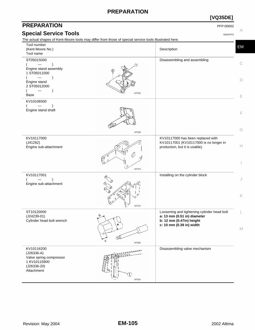
PREPARATION
EM-105
[VQ35DE]
C
D
E
F
G
H
I
J
K
L
M
A
EM
Revision: May 2004 2002 Altima
PREPARATION PFP:00002
Special Service Tools EBS007PS
The actual shapes of Kent-Moore tools may differ from those of special service tools illustrated here.
Tool number(Kent-Moore No.)Tool name
Description
ST0501S000( — )Engine stand assembly1 ST05011000( — )Engine stand2 ST05012000( — )Base
Disassembling and assembling
KV10106500( — )Engine stand shaft
KV10117000(J41262)Engine sub-attachment
KV10117000 has been replaced with KV10117001 (KV10117000 is no longer in production, but it is usable).
KV10117001( — )Engine sub-attachment
Installing on the cylinder block
ST10120000(J24239-01)Cylinder head bolt wrench
Loosening and tightening cylinder head bolta: 13 mm (0.51 in) diameterb: 12 mm (0.47in) heightc: 10 mm (0.39 in) width
KV10116200(J26336-A)Valve spring compressor1 KV10115900(J26336-20)Attachment
Disassembling valve mechanism
NT042
NT028
NT373
NT372
NT583
NT022

EM-106 Revision: May 2004
[VQ35DE]PREPARATION
2002 Altima
(J39386)Valve oil seal drift
Installing valve oil seal
EM03470000(J8037)Piston ring compressor
Installing piston assembly into cylinder bore
ST16610001(J23907)Pilot bushing puller
Removing crankshaft pilot bushing
KV10111100(J37228)Seal cutter
Removing steel oil pan and rear timing chain case
WS39930000( — )Tube presser
Pressing the tube of liquid gasket
KV10112100(BT8653-A)Angle wrench
Tightening bolts for bearing cap, cylinder head, etc.
KV10117100(J3647-A)Heated oxygen sensor wrench
Loosening or tightening heated oxygen sen-sorFor 22 mm (0.87 in) hexagon nut
Tool number(Kent-Moore No.)Tool name
Description
NT024
NT044
NT045
NT046
NT052
NT014
NT379
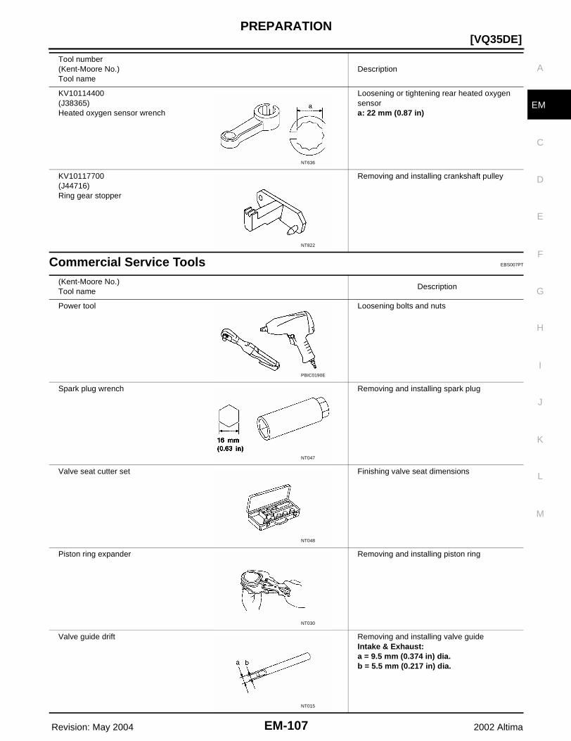
PREPARATION
EM-107
[VQ35DE]
C
D
E
F
G
H
I
J
K
L
M
A
EM
Revision: May 2004 2002 Altima
Commercial Service Tools EBS007PT
KV10114400(J38365)Heated oxygen sensor wrench
Loosening or tightening rear heated oxygen sensora: 22 mm (0.87 in)
KV10117700(J44716)Ring gear stopper
Removing and installing crankshaft pulley
Tool number(Kent-Moore No.)Tool name
Description
NT636
NT822
(Kent-Moore No.)Tool name
Description
Power tool Loosening bolts and nuts
Spark plug wrench Removing and installing spark plug
Valve seat cutter set Finishing valve seat dimensions
Piston ring expander Removing and installing piston ring
Valve guide drift Removing and installing valve guideIntake & Exhaust:a = 9.5 mm (0.374 in) dia.b = 5.5 mm (0.217 in) dia.
PBIC0190E
NT047
NT048
NT030
NT015

EM-108 Revision: May 2004
[VQ35DE]PREPARATION
2002 Altima
Valve guide reamer Reaming valve guide 1 or hole for oversize valve guide 2Intake & Exhaust:d1 = 6.0 mm (0.236 in) dia.d2 = 10.2 mm (0.402 in) dia.
(J-43897-18)(J-43897-12)Oxygen sensor thread cleaner
Reconditioning the exhaust system threads before installing a new oxygen sensor (use with anti-seize lubricant shown below)a = J-43897-18 (18 mm dia.) for zirconia ox-ygen sensorb = J-43897-12 (12 mm dia.) for titania oxy-gen sensor
Anti-seize lubricant (Permatex 133AR or equivalent meeting MIL specifica-tion MIL-A-907)
Lubricating oxygen sensor thread cleaning tool when reconditioning exhaust system threads
T55 Torx® bit Removing and installing the driveplate bolts (A/T), and the flywheel bolts (M/T)
(Kent-Moore No.)Tool name
Description
NT016
AEM488
AEM489
LBIA0286E
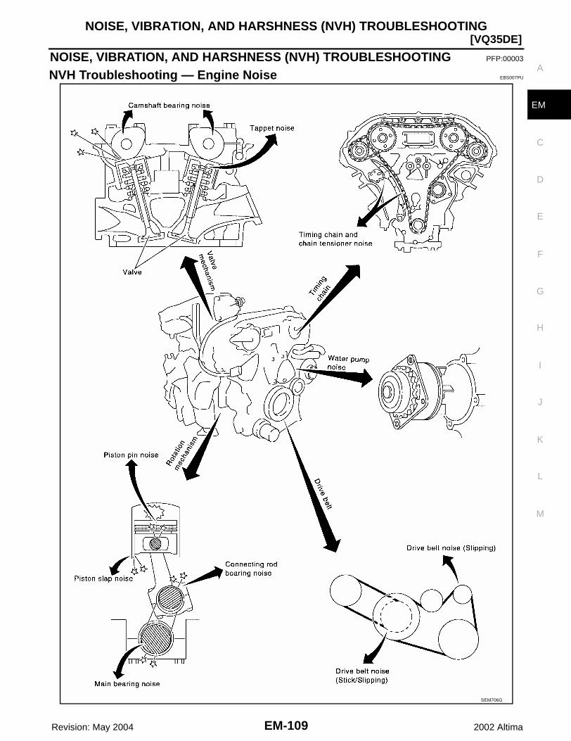
NOISE, VIBRATION, AND HARSHNESS (NVH) TROUBLESHOOTING
EM-109
[VQ35DE]
C
D
E
F
G
H
I
J
K
L
M
A
EM
Revision: May 2004 2002 Altima
NOISE, VIBRATION, AND HARSHNESS (NVH) TROUBLESHOOTING PFP:00003
NVH Troubleshooting — Engine Noise EBS007PU
SEM706G

EM-110 Revision: May 2004
[VQ35DE]NOISE, VIBRATION, AND HARSHNESS (NVH) TROUBLESHOOTING
2002 Altima
Use the Chart Below to Help You Find the Cause of the Symptom. EBS007PV
1. Locate the area where noise occurs.2. Confirm the type of noise.3. Specify the operating condition of engine.4. Check specified noise source. Repair or replace the identified part as necessary.
A: Closely related B: Related C: Sometimes related —: Not related
Location of noise
Type of noise
Operating condition of engine
Source of noise
Check itemRefer-
ence pageBefore warm-
up
After warm-
up
When start-ing
When idling
When racing
While driving
Top of engineRocker coverCylinder head
Ticking or clicking
C A — A B —Tappet noise
Valve clearance EM-166
Rattle C A — A B CCamshaft bearing noise
Camshaft journal clear-anceCamshaft runout
EM-136
Crank-shaft pul-leyCylinder block (Side of engine)Oil pan
Slap or knock
— A — B B —Piston pin noise
Piston and piston pin clearanceConnecting rod bush-ing clearance
EM-166
Slap or rap
A — — B B APiston slap noise
Piston-to-bore clear-ancePiston ring side clear-ancePiston ring end gapConnecting rod bend and torsion
EM-188
Knock A B C B B B
Connect-ing rod bearing noise
Connecting rod bush-ing clearance (Small end)Connecting rod bear-ing clearance (Big end)
EM-188
Knock A B — A B CMain bearing noise
Main bearing oil clear-anceCrankshaft runout
EM-188
Front of engineTiming chain cover
Tapping or ticking
A A — B B B
Timing chain and chain ten-sioner noise
Timing chain cracks and wearTiming chain tensioner operation
EM-148
Front of engine
Squeak-ing or fizz-ing
A B — B — C
Drive belts (Sticking or slip-ping)
Drive belts deflection
EM-111
Creaking A B A B A BDrive belts (Slipping)
Idler pulley bearing operation
SquallCreak
A B — B A BWater pump noise
Water pump operation CO-41
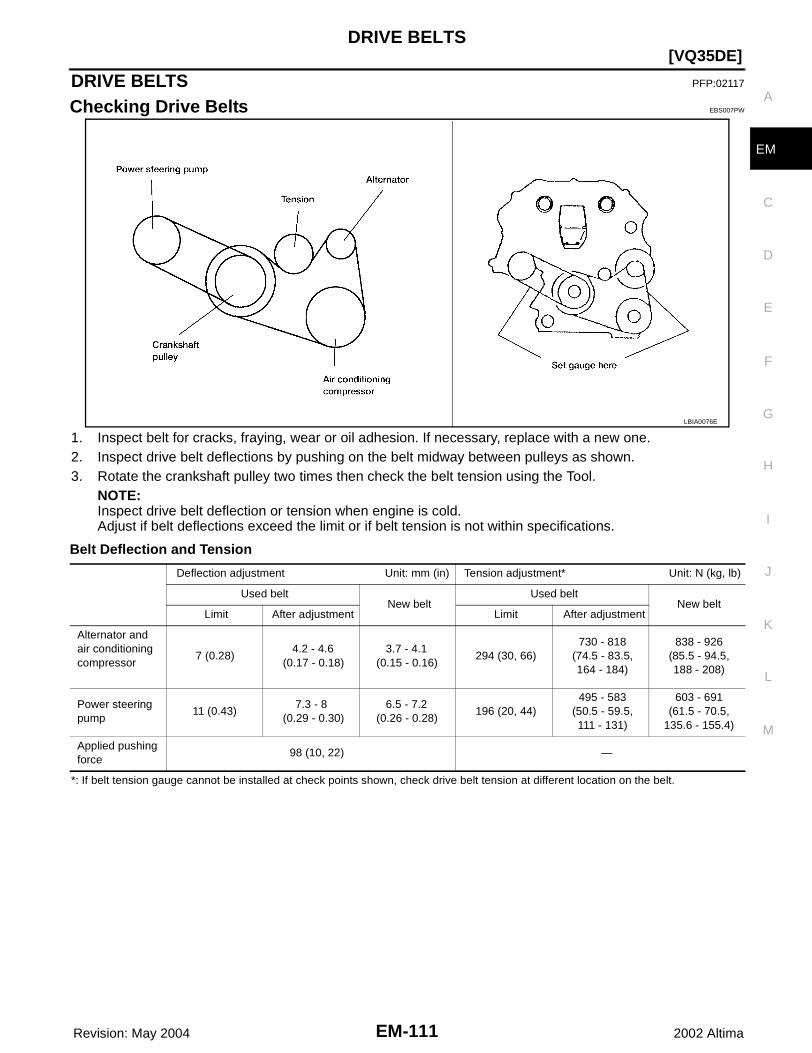
DRIVE BELTS
EM-111
[VQ35DE]
C
D
E
F
G
H
I
J
K
L
M
A
EM
Revision: May 2004 2002 Altima
DRIVE BELTS PFP:02117
Checking Drive Belts EBS007PW
1. Inspect belt for cracks, fraying, wear or oil adhesion. If necessary, replace with a new one.2. Inspect drive belt deflections by pushing on the belt midway between pulleys as shown.3. Rotate the crankshaft pulley two times then check the belt tension using the Tool.
NOTE:Inspect drive belt deflection or tension when engine is cold.Adjust if belt deflections exceed the limit or if belt tension is not within specifications.
Belt Deflection and Tension
*: If belt tension gauge cannot be installed at check points shown, check drive belt tension at different location on the belt.
LBIA0076E
Deflection adjustment Unit: mm (in) Tension adjustment* Unit: N (kg, lb)
Used beltNew belt
Used beltNew belt
Limit After adjustment Limit After adjustment
Alternator and air conditioning compressor
7 (0.28) 4.2 - 4.6 (0.17 - 0.18)
3.7 - 4.1 (0.15 - 0.16)
294 (30, 66)730 - 818
(74.5 - 83.5,164 - 184)
838 - 926(85.5 - 94.5,188 - 208)
Power steering pump
11 (0.43) 7.3 - 8 (0.29 - 0.30)
6.5 - 7.2 (0.26 - 0.28)
196 (20, 44)495 - 583
(50.5 - 59.5,111 - 131)
603 - 691(61.5 - 70.5,
135.6 - 155.4)
Applied pushing force
98 (10, 22) —

EM-112 Revision: May 2004
[VQ35DE]AIR CLEANER AND AIR DUCT
2002 Altima
AIR CLEANER AND AIR DUCT PFP:16500
Removal and Installation EBS007PX
REMOVAL1. Disconnect the harness connector from the mass air flow sensor.2. Disconnect the tube clamp at the electric throttle control actuator and at the fresh air intake tube.3. Remove air cleaner to electric throttle control actuator tube, air cleaner case (upper) with the mass air flow
sensor attached.4. Remove mass air flow sensor from air cleaner case (upper), as necessary.
CAUTION:Handle mass air flow sensor with care.● Do not shock it.● Do not disassemble it.● Do not touch its sensor.
5. Remove resonator in the fender, lifting left fender protector, as necessary.
INSTALLATIONInstallation is in the reverse order of removal.
CHANGING AIR CLEANER ELEMENT1. Unhook the air cleaner case side clips and lift up the air cleaner case (upper).
WBIA0038E
1. Resonator 2. Air cleaner to electric throttle control actuator tube
3. Grommet
4. Mass air flow sensor 5. Air cleaner case (upper) 6. Air cleaner case (lower)
7. Air cleaner case mounting bracket 8. Resonator in fender

AIR CLEANER AND AIR DUCT
EM-113
[VQ35DE]
C
D
E
F
G
H
I
J
K
L
M
A
EM
Revision: May 2004 2002 Altima
2. Remove the air cleaner element.3. Install the new air cleaner element, making sure it is facing in the correct direction.4. Install the air cleaner case (upper) and hook the air cleaner case side clips securely.

EM-114 Revision: May 2004
[VQ35DE]INTAKE MANIFOLD
2002 Altima
INTAKE MANIFOLD PFP:14003
Removal and Installation EBS007PY
WBIA0075E
1. Electric throttle control actuator 2. Intake manifold collector (upper) 3. EVAP canister purge volume control solenoid valve
4. Intake manifold collector (lower) 5. Power valve 6. VIAS control solenoid valve
7. Fuel tube 8. Fuel damper 9. Vacuum tank
10. Intake manifold 11. Service port
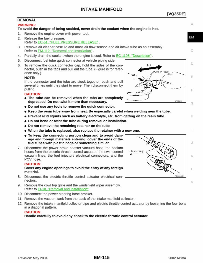
INTAKE MANIFOLD
EM-115
[VQ35DE]
C
D
E
F
G
H
I
J
K
L
M
A
EM
Revision: May 2004 2002 Altima
REMOVALWARNING:To avoid the danger of being scalded, never drain the coolant when the engine is hot.1. Remove the engine cover with power tool.2. Release the fuel pressure.
Refer to EC-51, "FUEL PRESSURE RELEASE" .3. Remove air cleaner case lid and mass air flow sensor, and air intake tube as an assembly.
Refer to EM-112, "Removal and Installation" .4. Partially drain the coolant when the engine is cool. Refer to EC-1108, "Description" .5. Disconnect fuel tube quick connector at vehicle piping side.6. To remove the quick connector cap, hold the sides of the con-
nector, push in the tabs and pull out the tube. (Figure is for refer-ence only.)NOTE:If the connector and the tube are stuck together, push and pullseveral times until they start to move. Then disconnect them bypulling.CAUTION:● The tube can be removed when the tabs are completely
depressed. Do not twist it more than necessary.● Do not use any tools to remove the quick connector.● Keep the resin tube away from heat. Be especially careful when welding near the tube.● Prevent acid liquids such as battery electrolyte, etc. from getting on the resin tube.● Do not bend or twist the tube during removal or installation.● Do not remove the remaining retainer on the tube● When the tube is replaced, also replace the retainer with a new one.● To keep the connecting portion clean and to avoid dam-
age and foreign materials entering, cover the ends of thefuel tubes with plastic bags or something similar.
7. Disconnect the power brake booster vacuum hose, the coolanthoses from the electric throttle control actuator, the swirl controlvacuum lines, the fuel injectors electrical connectors, and thePCV hose.CAUTION:Cover any engine openings to avoid the entry of any foreignmaterial.
8. Disconnect the electric throttle control actuator electrical con-nectors.
9. Remove the cowl top grille and the windshield wiper assembly.Refer to EI-18, "Removal and Installation" .
10. Disconnect the power steering hose bracket.11. Remove the vacuum tank from the back of the intake manifold collector.12. Remove the intake manifold collector pipe and electric throttle control actuator by loosening the four bolts
in a diagonal pattern.CAUTION:Handle carefully to avoid any shock to the electric throttle control actuator.
SFE562A
PBIC0163E
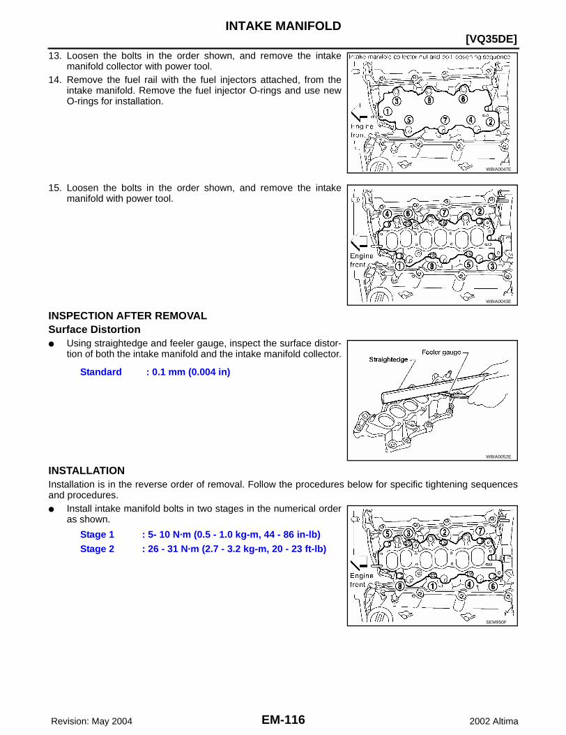
EM-116 Revision: May 2004
[VQ35DE]INTAKE MANIFOLD
2002 Altima
13. Loosen the bolts in the order shown, and remove the intakemanifold collector with power tool.
14. Remove the fuel rail with the fuel injectors attached, from theintake manifold. Remove the fuel injector O-rings and use newO-rings for installation.
15. Loosen the bolts in the order shown, and remove the intakemanifold with power tool.
INSPECTION AFTER REMOVALSurface Distortion● Using straightedge and feeler gauge, inspect the surface distor-
tion of both the intake manifold and the intake manifold collector.
INSTALLATIONInstallation is in the reverse order of removal. Follow the procedures below for specific tightening sequencesand procedures.● Install intake manifold bolts in two stages in the numerical order
as shown.
WBIA0047E
WBIA0043E
Standard : 0.1 mm (0.004 in)
WBIA0052E
Stage 1 : 5- 10 N·m (0.5 - 1.0 kg-m, 44 - 86 in-lb)Stage 2 : 26 - 31 N·m (2.7 - 3.2 kg-m, 20 - 23 ft-lb)
SEM950F

INTAKE MANIFOLD
EM-117
[VQ35DE]
C
D
E
F
G
H
I
J
K
L
M
A
EM
Revision: May 2004 2002 Altima
● Seat the fuel injectors into the intake manifold with new O-rings.Tighten the fuel rail bolts as shown, in two stages:
● Install the intake manifold collector bolts in the numerical orderas shown.
● Tighten the mounting bolts of the intake manifold collector pipe and electric throttle control actuatorassembly equally and diagonally to specification.
● Install the quick connector as follows:– Make sure no foreign substances are deposited in and around the fuel tube and quick connector and that
there is no damage. – Align the center to insert the quick connector straight onto the
fuel tube.– Insert the fuel tube until a click is heard.– Install the quick connector cap on the quick connector joint.
Align the arrow mark on the quick connector cap to the upperside.
– Install the fuel hose into the hose clamp.
NOTE:After installation, it is necessary to re-calibrate the electric throttle control actuator as follows:1. Perform the "Throttle Valve Closed Position Learning" when harness connector of the electric throttle con-
trol actuator is disconnected. Refer to EC-656, "BASIC SERVICE PROCEDURE" .2. Perform the "Idle Air Volume Learning" when the electric throttle control actuator is replaced. Refer to EC-
656, "BASIC SERVICE PROCEDURE" .
Stage 1 : 9.3 - 10.8 N·m (0.95 - 1.1 kg-m, 83 - 95 in-lb)Stage 2 : 21 - 26 N·m (2.1 - 2.7 kg-m, 15 - 20 ft-lb)
WBIA0053E
Intake manifold collector bolts
: 18 - 21 N·m (1.8 - 2.2 kg-m, 13 - 15 ft-lb)
WBIA0049E
Electric throttle control actuator bolts : 7.2 - 9.6 N·m (0.74 - 0.97 kg-m, 64 - 84 in-lb)
KBIA0298E
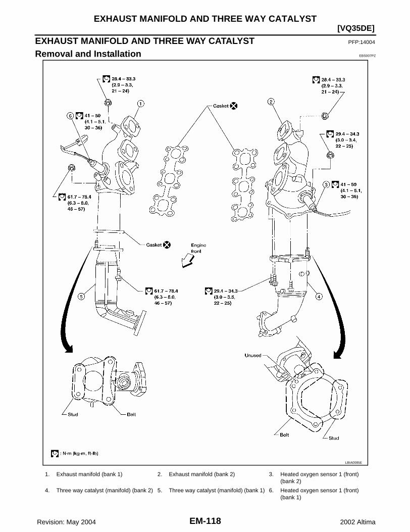
EM-118 Revision: May 2004
[VQ35DE]EXHAUST MANIFOLD AND THREE WAY CATALYST
2002 Altima
EXHAUST MANIFOLD AND THREE WAY CATALYST PFP:14004
Removal and Installation EBS007PZ
LBIA0085E
1. Exhaust manifold (bank 1) 2. Exhaust manifold (bank 2) 3. Heated oxygen sensor 1 (front) (bank 2)
4. Three way catalyst (manifold) (bank 2) 5. Three way catalyst (manifold) (bank 1) 6. Heated oxygen sensor 1 (front) (bank 1)

EXHAUST MANIFOLD AND THREE WAY CATALYST
EM-119
[VQ35DE]
C
D
E
F
G
H
I
J
K
L
M
A
EM
Revision: May 2004 2002 Altima
REMOVALWARNING:● Perform the work when the exhaust and cooling system have completely cooled down.● When removing the front and rear engine mounting through bolts and nuts, lift the engine up
slightly for safety. For engine slingers, refer to step 17 in EM-185, "REMOVAL" .1. Remove the front wheel and tires with power tool.2. Remove the engine undercovers with power tool.3. Remove the inner wheel well splash shields with power tool.4. Remove the radiator and cooling fan assembly.
Refer to EC-1085, "Component Description" .5. Remove the front exhaust tube.
Refer to EX-6, "Removal and Installation" .6. Remove the front suspension member as follows:
CAUTION:Before disconnecting, support the front suspension mem-ber with a suitable power lift. Use the lift to lower the mem-ber to remove it.
a. Disconnect the lower ball joints.Refer to FSU-14, "FRONT SUSPENSION MEMBER" .
b. Remove the steering gear mounting bolts.Refer to PS-13, "Removal and Installation" .
c. Disconnect the upper sway bar connecting rod.Refer to FSU-11, "Removal and Installation" .
d. Disconnect the front and rear engine mounts electrical connec-tors, if equipped. Remove the front and rear engine mountthrough bolts and nuts using power tool.CAUTION:For vehicles equipped with an automatic transaxle, the front and rear engine mounts are electri-cally controlled. Disconnect the engine mount electrical connector(s) before removing the throughbolt and nut.
e. Disconnect the power steering line bracket.f. Remove the LH and RH drive axles.
Refer to FAX-11, "Removal and Installation" .g. Remove the front suspension member mounting nuts and lower the member out of the engine compart-
ment.7. Remove heated oxygen sensor 1 (front) (bank 1) and heated oxygen sensor 2 (front) (bank 2).
WBIA0034E
SEM471G
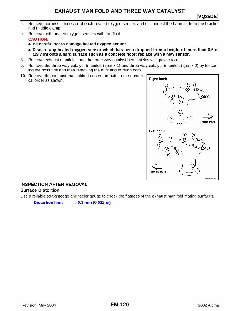
EM-120 Revision: May 2004
[VQ35DE]EXHAUST MANIFOLD AND THREE WAY CATALYST
2002 Altima
a. Remove harness connector of each heated oxygen sensor, and disconnect the harness from the bracketand middle clamp.
b. Remove both heated oxygen sensors with the Tool.CAUTION:● Be careful not to damage heated oxygen sensor.● Discard any heated oxygen sensor which has been dropped from a height of more than 0.5 m
(19.7 in) onto a hard surface such as a concrete floor; replace with a new sensor.8. Remove exhaust manifolds and the three way catalyst heat shields with power tool.9. Remove the three way catalyst (manifold) (bank 1) and three way catalyst (manifold) (bank 2) by loosen-
ing the bolts first and then removing the nuts and through bolts.10. Remove the exhaust manifolds. Loosen the nuts in the numeri-
cal order as shown.
INSPECTION AFTER REMOVALSurface DistortionUse a reliable straightedge and feeler gauge to check the flatness of the exhaust manifold mating surfaces.
WBIA0055E
Distortion limit : 0.3 mm (0.012 in)

EXHAUST MANIFOLD AND THREE WAY CATALYST
EM-121
[VQ35DE]
C
D
E
F
G
H
I
J
K
L
M
A
EM
Revision: May 2004 2002 Altima
INSTALLATIONInstallation is in the reverse order of removal.● Install the exhaust manifold nuts in the numerical order as
shown.CAUTION:● When using the heated oxygen sensor wrench, tighten to
the middle of specified torque range, because the length ofthe Tool may increase the actual tightness. Do not tightento the maximum specified torque range.
● Before installing a heated oxygen sensor, clean the exhaustmanifold threads using the oxygen sensor thread cleanertool, and apply anti-seize lubricant.
● Do not over-torque the heated oxygen sensors. Doing somay cause damage to the heated oxygen sensors.
WBIA0056E
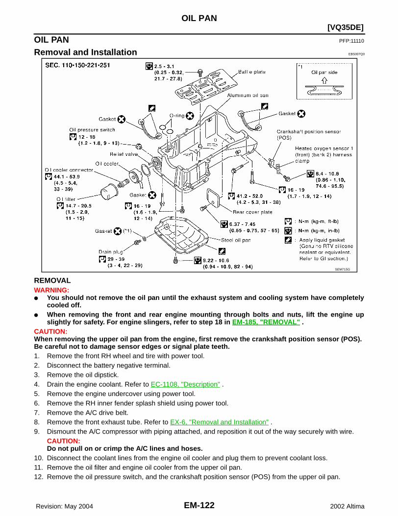
EM-122 Revision: May 2004
[VQ35DE]OIL PAN
2002 Altima
OIL PAN PFP:11110
Removal and Installation EBS007Q0
REMOVALWARNING:● You should not remove the oil pan until the exhaust system and cooling system have completely
cooled off.● When removing the front and rear engine mounting through bolts and nuts, lift the engine up
slightly for safety. For engine slingers, refer to step 18 in EM-185, "REMOVAL" .CAUTION:When removing the upper oil pan from the engine, first remove the crankshaft position sensor (POS).Be careful not to damage sensor edges or signal plate teeth.1. Remove the front RH wheel and tire with power tool.2. Disconnect the battery negative terminal.3. Remove the oil dipstick.4. Drain the engine coolant. Refer to EC-1108, "Description" .5. Remove the engine undercover using power tool.6. Remove the RH inner fender splash shield using power tool.7. Remove the A/C drive belt.8. Remove the front exhaust tube. Refer to EX-6, "Removal and Installation" .9. Dismount the A/C compressor with piping attached, and reposition it out of the way securely with wire.
CAUTION:Do not pull on or crimp the A/C lines and hoses.
10. Disconnect the coolant lines from the engine oil cooler and plug them to prevent coolant loss.11. Remove the oil filter and engine oil cooler from the upper oil pan.12. Remove the oil pressure switch, and the crankshaft position sensor (POS) from the upper oil pan.
SEM715G

OIL PAN
EM-123
[VQ35DE]
C
D
E
F
G
H
I
J
K
L
M
A
EM
Revision: May 2004 2002 Altima
13. Remove the front suspension member, as follows:
CAUTION:Before disconnecting, support the front suspension mem-ber with a suitable power lift. Use the lift to lower the frontsuspension member to remove it.
a. Disconnect the lower ball jointsRefer to FSU-5, "FRONT SUSPENSION ASSEMBLY" .
b. Disconnect the power steering line bracket.c. Disconnect the steering gear mounting bolts.
Refer to PS-13, "Removal and Installation" .d. Disconnect the upper sway bar links.
Refer to FSU-5, "FRONT SUSPENSION ASSEMBLY" .e. Remove the LH and RH drive axles.
Refer to FAX-11, "Removal and Installation" .f. Disconnect the front engine mounts electrical connectors, if equipped. Remove the front and rear engine
mounts through bolts and nuts using power tool.WARNING:For additional safety, support the engine from above with a suitable hoist.CAUTION:For vehicles equipped with an automatic transaxle, the front and rear engine mounts are electri-cally controlled. Disconnect the engine mount electrical connector before removing the throughbolt.
g. Remove the front suspension member mounting nuts and lower the member out of the engine compart-ment.
14. Disconnect the heated oxygen sensors and remove the two catalytic convertors from the exhaust mani-folds using power tool.
15. Remove the rear plate cover from the upper oil pan.
WBIA0034E
SEM471G
SEM717G
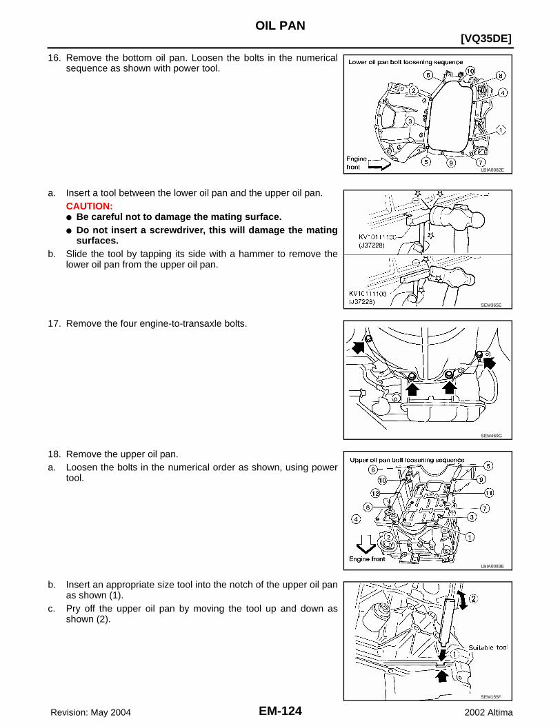
EM-124 Revision: May 2004
[VQ35DE]OIL PAN
2002 Altima
16. Remove the bottom oil pan. Loosen the bolts in the numericalsequence as shown with power tool.
a. Insert a tool between the lower oil pan and the upper oil pan.CAUTION:● Be careful not to damage the mating surface.● Do not insert a screwdriver, this will damage the mating
surfaces.b. Slide the tool by tapping its side with a hammer to remove the
lower oil pan from the upper oil pan.
17. Remove the four engine-to-transaxle bolts.
18. Remove the upper oil pan.a. Loosen the bolts in the numerical order as shown, using power
tool.
b. Insert an appropriate size tool into the notch of the upper oil panas shown (1).
c. Pry off the upper oil pan by moving the tool up and down asshown (2).
LBIA0082E
SEM365E
SEM469G
LBIA0083E
SEM155F

OIL PAN
EM-125
[VQ35DE]
C
D
E
F
G
H
I
J
K
L
M
A
EM
Revision: May 2004 2002 Altima
19. Remove the O-ring seals from the bottom of the cylinder blockand oil pump housing, use new O-rings for installation.
20. Remove front cover gasket and rear oil seal retainer gasket.
21. If re-installing the original oil pan, remove the old sealant fromthe mating surfaces using a scraper.● Also remove the old sealant from mating surface of the cylin-
der block.● Remove the old sealant from the bolt holes and threads.CAUTION:Do not scratch or damage the mating surfaces when clean-ing off the old sealant.
INSTALLATION1. Installation is in the reverse order of removal.
CAUTION:Wait at least 30 minutes before refilling the engine with oil.
a. Apply Genuine RTV Silicone Sealant or equivalent, to the frontcover gasket and the rear oil seal retainer gasket as shown.Refer to GI-42, "RECOMMENDED CHEMICAL PRODUCTSAND SEALANTS" .
SEM464G
SEM465G
MEM108A
SEM964E

EM-126 Revision: May 2004
[VQ35DE]OIL PAN
2002 Altima
b. Install the front cover gasket and rear oil seal retainer gasket asshown.
c. Apply a bead of sealant to the cylinder block mating surface ofthe upper oil pan to a limited portion as shown.● Use Genuine RTV Silicone Sealant, or equivalent. Refer to
GI-42, "RECOMMENDED CHEMICAL PRODUCTS ANDSEALANTS" .
● Be sure the sealant is applied to a limited portion as shown,and the sealant is 4.0 - 5.0 mm (0.157 - 0.197 in) or 4.5 - 5.5mm (0.177 - 0.217 in) wide.
● Attaching should be done within 5 minutes after coating.
d. Install new O-rings on the cylinder block and oil pump body.
e. Install the upper oil pan.● Tighten bolts in numerical order.● Wait at least 30 minutes before refilling the engine with oil.
SEM465G
SEM185FA
SEM159F
SEM464G
LBIA0084E

OIL PAN
EM-127
[VQ35DE]
C
D
E
F
G
H
I
J
K
L
M
A
EM
Revision: May 2004 2002 Altima
f. Install the four engine-to-transmission bolts. Refer to EM-184,"Removal and Installation" .
g. Apply a continuous bead of sealant to the lower oil pan.● Use Genuine RTV Silicone Sealant, or equivalent. Refer to
GI-42, "RECOMMENDED CHEMICAL PRODUCTS ANDSEALANTS" .
● Be sure the sealant is 4.5 - 5.5 mm (0.177 - 0.217 in) wide.● Attaching should be done within 5 minutes after coating.
h. Install the lower oil pan. Tighten the bolts in the numerical orderas shown.● Wait at least 30 minutes before refilling the engine with oil.
SEM469G
SEM159F
WBIA0050E

EM-128 Revision: May 2004
[VQ35DE]IGNITION COIL
2002 Altima
IGNITION COIL PFP:22448
Removal and Installation EBS007Q1
REMOVAL1. Remove the engine cover, with power tool.2. Drain engine coolant. Refer to MA-22, "DRAINING ENGINE COOLANT" .3. Disconnect the mass air flow sensor electrical connector and remove the air cleaner assembly and air
intake tubes. Refer to EM-112, "Removal and Installation" .4. Remove the windshield wiper arms and motor assembly and the front cowl panel. Refer to EI-18,
"Removal and Installation" .5. Remove the intake manifold collector, gasket, and throttle body. Refer to EM-114, "Removal and Installa-
tion" .6. Remove the six ignition coils.
INSTALLATIONInstallation is in the reverse order of removal.
WBIA0040E
1. Ignition coil 2. Spark plug 3. Rocker cover (right bank)
4. Rocker cover (left bank)

SPARK PLUG (PLATINUM-TIPPED TYPE)
EM-129
[VQ35DE]
C
D
E
F
G
H
I
J
K
L
M
A
EM
Revision: May 2004 2002 Altima
SPARK PLUG (PLATINUM-TIPPED TYPE) PFP:22401
Removal and Installation EBS007Q2
REMOVAL1. Remove the engine cover, with power tool.2. Drain engine coolant. Refer to MA-22, "DRAINING ENGINE COOLANT" .3. Disconnect the mass air flow sensor electrical connector and remove the air cleaner assembly and air
intake tubes. Refer to EM-112, "Removal and Installation" .4. Remove the windshield wiper arms and motor assembly and the front cowl panel. Refer to EI-18,
"Removal and Installation" .5. Remove the intake manifold collector, gasket, and throttle body. Refer to EM-114, "Removal and Installa-
tion" .6. Remove the six ignition coils.7. Remove the six spark plugs with a suitable tool.
● If replacing the spark plugs use the correct spark plug formaximum performance. Refer to MA-26, "Changing SparkPlugs (Platinum - Tipped Type)" .
WBIA0040E
1. Ignition coil 2. Spark plug 3. Rocker cover (right bank)
4. Rocker cover (left bank)
SEM294A
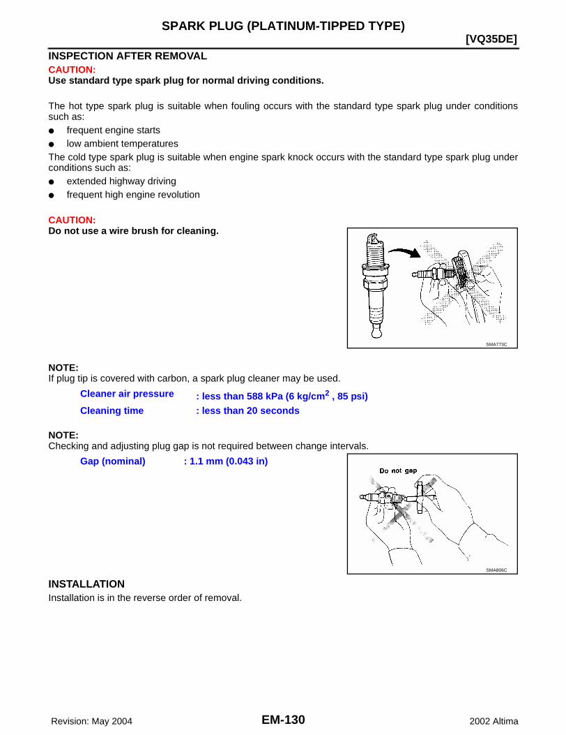
EM-130 Revision: May 2004
[VQ35DE]SPARK PLUG (PLATINUM-TIPPED TYPE)
2002 Altima
INSPECTION AFTER REMOVALCAUTION:Use standard type spark plug for normal driving conditions.
The hot type spark plug is suitable when fouling occurs with the standard type spark plug under conditionssuch as:● frequent engine starts● low ambient temperaturesThe cold type spark plug is suitable when engine spark knock occurs with the standard type spark plug underconditions such as:● extended highway driving● frequent high engine revolution
CAUTION:Do not use a wire brush for cleaning.
NOTE:If plug tip is covered with carbon, a spark plug cleaner may be used.
NOTE:Checking and adjusting plug gap is not required between change intervals.
INSTALLATIONInstallation is in the reverse order of removal.
SMA773C
Cleaner air pressure : less than 588 kPa (6 kg/cm2 , 85 psi)Cleaning time : less than 20 seconds
Gap (nominal) : 1.1 mm (0.043 in)
SMA806C

FUEL INJECTOR AND FUEL TUBE
EM-131
[VQ35DE]
C
D
E
F
G
H
I
J
K
L
M
A
EM
Revision: May 2004 2002 Altima
FUEL INJECTOR AND FUEL TUBE PFP:16600
Removal and Installation EBS007Q3
CAUTION:● Apply new engine oil when installing the parts that specified to do so in the figure.● Do not remove or disassemble parts unless instructed as shown in the figure.
REMOVALWARNING:To avoid the danger of being scalded, never drain the coolant when the engine is hot.1. Remove the engine cover using power tool.2. Release the fuel pressure.
Refer to EC-670, "FUEL PRESSURE RELEASE" .3. Remove air cleaner case lid and mass air flow sensor, and air intake tube as an assembly.
Refer to EM-112, "Removal and Installation" .4. Partially drain the coolant when the engine is cool. Refer to EC-1108, "Description" .5. Disconnect fuel tube quick connector at vehicle piping side.
Refer to step 5 of EM-115, "REMOVAL" .6. Disconnect the power brake booster vacuum hose, the coolant hoses from the electric throttle control
actuator, the swirl control vacuum lines, the fuel injectors electrical connectors, and the PCV hose.CAUTION:Cover any engine openings to avoid the entry of any foreign material.
7. Disconnect the electric throttle control actuator electrical connector and coolant hoses.8. Remove the cowl top grille and the windshield wiper assembly.
Refer to EI-18, "Removal and Installation" .9. Disconnect the power steering hose bracket.
WBIA0054E

EM-132 Revision: May 2004
[VQ35DE]FUEL INJECTOR AND FUEL TUBE
2002 Altima
10. Remove the vacuum tank from the back of the intake manifold collector.11. Remove the intake manifold collector pipe and electric throttle control actuator, by loosening the four bolts
in a diagonal pattern.CAUTION:Handle carefully to avoid any shock to the electric throttle control actuator.
12. Loosen the bolts in the order shown, and remove the intakemanifold collector using power tool.
13. Remove the fuel rail with the fuel injectors attached, from theintake manifold. Remove the fuel injector O-rings and use newO-rings for installation.
INSTALLATION1. Installation is in the reverse order of removal.
● Carefully install new O-rings, including the one used with thefuel damper.
● Lubricate O-rings by lightly coating with new engine oil.● Be careful not to damage the O-rings and surfaces for O-
ring sealing surfaces. Do not expand or twist O-rings.● Discard old clips; replace with new ones.● Position clips in grooves on the fuel injectors.● Make sure that protrusions of fuel injectors are aligned
with cutouts of clips after installation.● Align the protrusions of the fuel tube assembly with those of
the fuel injectors.● After properly inserting the fuel injectors onto the fuel tube assembly, check that the fuel tube protru-
sions are engaged with those of fuel injectors, and the flanges of the fuel tube assembly are fullyengaged with the clips.
● Tighten fuel tube assembly mounting bolts as shown, in twosteps:
CAUTION:● After properly connecting fuel tube assembly to injector
and fuel hose, check connection for fuel leakage.
● Install the intake manifold collector bolts in the numericalorder as shown.
WBIA0047E
1st step : 9.3 - 10.8 N·m (0.95 - 1.1 kg-m, 6.2 - 7.9 ft-lb)
2nd step : 20.6 - 26.5 N·m (2.1 - 2.7 kg-m, 16 - 19 ft-lb)
SEF703X
WBIA0053E
Intake manifold collector bolts
: 18 - 21 N·m (1.8 - 2.2 kg-m, 13 - 15 ft-lb
WBIA0049E

FUEL INJECTOR AND FUEL TUBE
EM-133
[VQ35DE]
C
D
E
F
G
H
I
J
K
L
M
A
EM
Revision: May 2004 2002 Altima
● Tighten the mounting bolts of the intake manifold collector pipe and electric throttle control actuatorassembly diagonally to specification.
● After installation, it is necessary to re-calibrate the electric throttle control actuator.– Perform "Throttle Control Closed Position Learning" when the harness connector of the electric throttle
control actuator is disconnected. Refer to EC-656, "BASIC SERVICE PROCEDURE" .– Perform "Idle Air Volume Learning" when the electric throttle control actuator is replaced. Refer to EC-
656, "BASIC SERVICE PROCEDURE" .● Install the quick connector.
Refer to EM-116, "INSTALLATION" .
INSPECTION AFTER INSTALLATIONCheck for fuel leaks1. Start the engine, and run it for a few minutes with the engine at idle.2. Stop the engine, and check for fuel leaks both visually and by odor.
NOTE:Use mirrors for checking at points out of clear sight.CAUTION:Do not touch the engine immediately after stopped, as engine becomes extremely hot.
Electric throttle control actuator bolts : 7.2 - 9.8 N·m (0.74 - 0.97 kg-m, 64 - 84 ft-lb)

EM-134 Revision: May 2004
[VQ35DE]ROCKER COVER
2002 Altima
ROCKER COVER PFP:13264
Removal and Installation EBS007Q4
REMOVAL1. Remove the engine cover, using power tool.2. Drain engine coolant. Refer to MA-22, "DRAINING ENGINE COOLANT" .3. Disconnect the mass air flow sensor electrical connector and remove the air cleaner assembly and air
intake tubes. Refer to EM-112, "Removal and Installation" .4. Remove the windshield wiper arms and motor assembly and the front cowl panel. Refer to WW-25,
"Removal and Installation for Wiper Motor and Linkage" .5. Remove the intake manifold collector using power tool. Remove gasket and the electric throttle control
actuator. Refer to EM-114, "Removal and Installation" .6. Remove the six ignition coils. Refer to EM-128, "Removal and Installation" .7. Remove the two intake valve timing control solenoid valves and gaskets. Refer to EC-771, "INTAKE
VALVE TIMING CONTROL SOLENOID VALVE" .
LBIA0077E
1. Rocker cover (left bank) 2. PCV valve 3. Rocker cover (right bank)
4. Rocker cover gasket (right bank) 5. Rocker cover (left bank) 6. Oil filler cap

ROCKER COVER
EM-135
[VQ35DE]
C
D
E
F
G
H
I
J
K
L
M
A
EM
Revision: May 2004 2002 Altima
8. Remove RH and LH rocker covers from cylinder head.● Follow the loosening sequence for each side rocker cover
bolts as shown.
INSTALLATIONInstallation is in the reverse order of removal.● Apply sealant to the areas on the front corners. Refer to EM-
150, "POSITION FOR APPLYING LIQUID GASKET" .● Use Genuine RTV Silicone Sealant or equivalent. Refer to GI-
42, "RECOMMENDED CHEMICAL PRODUCTS AND SEAL-ANTS" .
● Tighten the rocker cover bolts in two stages and in the numericalorder as shown.
LBIA0078E
Stage 1 rocker cover bolts
: 0.96 - 2.96 N·m (0.10 - 0.30 kg-m, 9 - 26 in-lb)
Stage 2 rocker cover bolts
: 7.33 - 9.33 N·m (0.75 - 0.95 kg-m, 65 - 82 in-lb)
WBIA0039E
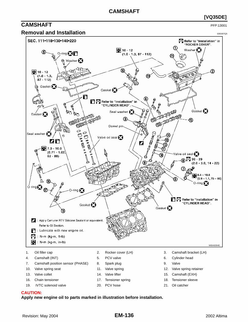
EM-136 Revision: May 2004
[VQ35DE]CAMSHAFT
2002 Altima
CAMSHAFT PFP:13001
Removal and Installation EBS007Q5
CAUTION:Apply new engine oil to parts marked in illustration before installation.
WBIA0094E
1. Oil filler cap 2. Rocker cover (LH) 3. Camshaft bracket (LH)
4. Camshaft (INT) 5. PCV valve 6. Cylinder head
7. Camshaft position sensor (PHASE) 8. Spark plug 9. Valve
10. Valve spring seat 11. Valve spring 12. Valve spring retainer
13. Valve collet 14. Valve lifter 15. Camshaft (EXH)
16. Chain tensioner 17. Tensioner spring 18. Tensioner sleeve
19. IVTC solenoid valve 20. PCV hose 21. Oil catcher

CAMSHAFT
EM-137
[VQ35DE]
C
D
E
F
G
H
I
J
K
L
M
A
EM
Revision: May 2004 2002 Altima
REMOVAL1. Remove the timing chains. Refer to EM-151, "Removal" .2. Remove the fuel rail and injectors. Refer to EM-131, "Removal and Installation" .3. Remove the IVTC (intake valve timing control) solenoid valves.
● Discard the IVTC solenoid valve gaskets and use new gas-kets for installation.
4. Remove the intake and exhaust camshaft brackets and the cam-shafts.● Mark the camshafts, camshaft brackets, and bolts so they are
placed in the same position and direction for installation.● Equally loosen the camshaft bracket bolts in several steps in
the numerical order shown.
INSTALLATION1. Before installation, remove any old RTV Silicone Sealant from
component mating surfaces using a scraper.● Remove the old RTV Silicone Sealant from the bolt holes and
threads.● Do not scratch or damage the mating surfaces.
WBIA0044E
SEM856E
SEM857E
SEM161F

EM-138 Revision: May 2004
[VQ35DE]CAMSHAFT
2002 Altima
2. Before installing the front cam bracket, remove the old RTV Sili-cone Sealant from the mating surface using a scraper.● Do not scratch or damage the mating surface.
3. Turn the crankshaft until No. 1 piston is set at TDC on the com-pression stroke.● The crankshaft key should line up with the right bank cylinder
center line as shown.
4. Install camshaft chain tensioners on both sides of cylinder head.
5. Install exhaust and intake camshafts and camshaft brackets.● Intake camshaft has a drill mark on camshaft sprocket mount-
ing flange.
● Follow your identification marks made during removal, or fol-low the identification marks that are present on the new cam-shafts components for proper placement and direction of thecomponents.
SEM892E
SEM532G
Camshaft chain tensioner bolts
: 7 - 10 N·m (0.7 - 1.0 kg-m, 62 - 89 in-lb)
SEM444G
SEM652F
Bank INT/EXH ID mark Drill markPaint marks
M1 M2
RHINT RE Yes Yes No
EXH RE No No Yes
SEM653F

CAMSHAFT
EM-139
[VQ35DE]
C
D
E
F
G
H
I
J
K
L
M
A
EM
Revision: May 2004 2002 Altima
● Position the camshafts:RH exhaust camshaft dowel pin at about 10 o'clock.LH exhaust camshaft dowel pin at about 2 o'clock.
6. Before installing camshaft brackets, apply sealant to mating sur-face of No. 1 camshaft bracket.● Use Genuine RTV Silicone Sealant, or equivalent. Refer to
GI-42, "RECOMMENDED CHEMICAL PRODUCTS ANDSEALANTS" .
LHINT LH Yes Yes No
EXH LH No No Yes
Bank INT/EXH ID mark Drill markPaint marks
M1 M2
SEM533G
SEM446G

EM-140 Revision: May 2004
[VQ35DE]CAMSHAFT
2002 Altima
● Before installation, wipe off any protruding sealant.● Refer to EM-104, "LIQUID GASKET APPLICATION PROCE-
DURE" .
● Install camshaft brackets in their original positions and direc-tion. Align the stamp marks as shown.
● If checking and adjusting any part of valve assembly or cam-shaft, check valve clearance according to the reference data.Refer to EM-143, "Valve Clearance" .
● Lubricate the threads and seat surfaces of the camshaftbracket bolts with new engine oil before installation.
● Tighten the camshaft brackets in the following steps, in numerical order as shown.
WBIA0089E
Valve clearance (cold) Intake : 0.26 - 0.34 mm (0.010 - 0.013 in)
Valve clearance (cold) Exhaust : 0.29 - 0.37 mm (0.011 - 0.015 in)
SEM564G
Step Tightening torque Tightening order
1 1.96 N·m (0.2 kg-m, 17 in-lb)Tighten No.s 7 to 10, then tighten 1
to 6 in order as shown.
2 6 N·m (0.6 kg-m, 52 in-lb)Tighten in numerical order as
shown.
39.02 - 11.8 N·m (0.92 - 1.20 kg-m,
79.9 - 104.2 in-lb)Tighten No. 1 -6 in the numerical
order as shown.
48.30 - 10.3 N·m (0.90 - 1.00 kg-m,
74 - 91 in-lb) Tighten No. 7 - 10 in the numerical
order as shownSEM885EA
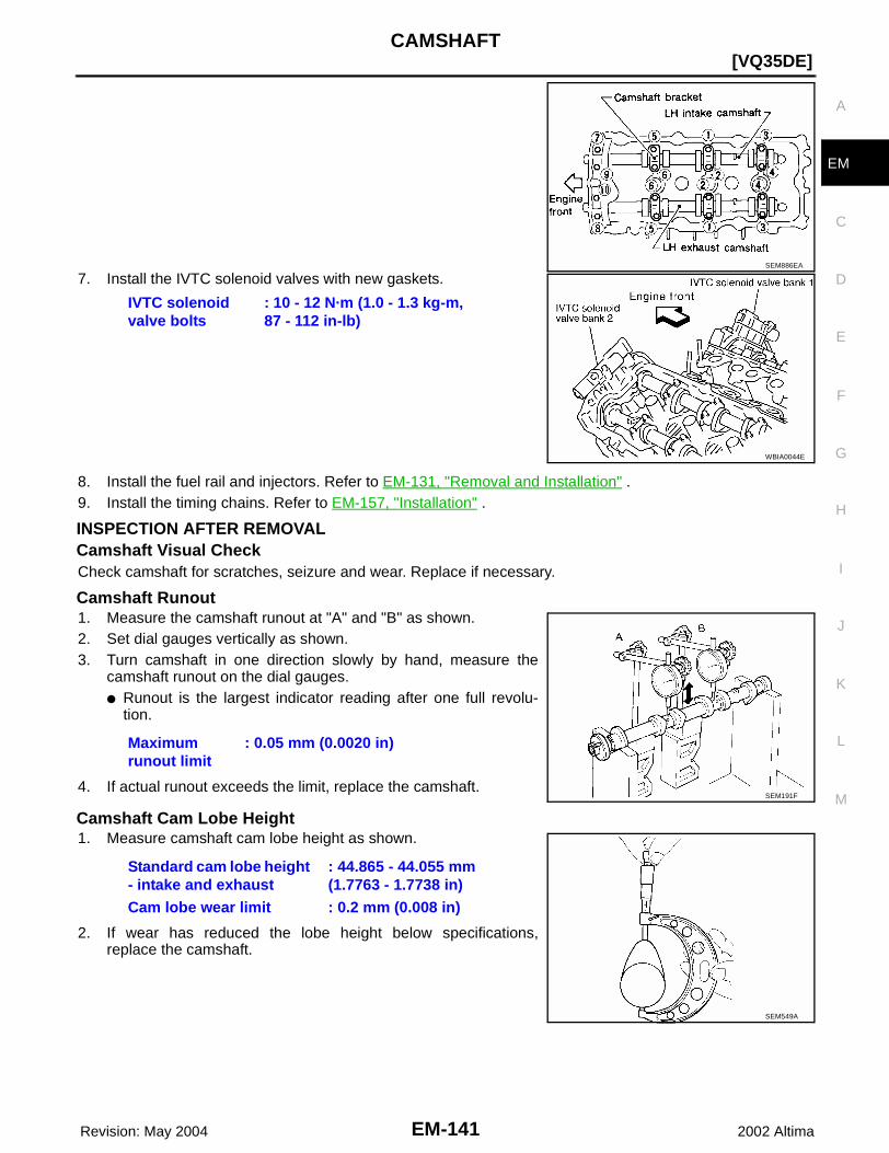
CAMSHAFT
EM-141
[VQ35DE]
C
D
E
F
G
H
I
J
K
L
M
A
EM
Revision: May 2004 2002 Altima
7. Install the IVTC solenoid valves with new gaskets.
8. Install the fuel rail and injectors. Refer to EM-131, "Removal and Installation" .9. Install the timing chains. Refer to EM-157, "Installation" .
INSPECTION AFTER REMOVALCamshaft Visual Check Check camshaft for scratches, seizure and wear. Replace if necessary.
Camshaft Runout1. Measure the camshaft runout at "A" and "B" as shown.2. Set dial gauges vertically as shown.3. Turn camshaft in one direction slowly by hand, measure the
camshaft runout on the dial gauges.● Runout is the largest indicator reading after one full revolu-
tion.
4. If actual runout exceeds the limit, replace the camshaft.
Camshaft Cam Lobe Height1. Measure camshaft cam lobe height as shown.
2. If wear has reduced the lobe height below specifications,replace the camshaft.
SEM886EA
IVTC solenoid valve bolts
: 10 - 12 N·m (1.0 - 1.3 kg-m, 87 - 112 in-lb)
WBIA0044E
Maximum runout limit
: 0.05 mm (0.0020 in)
SEM191F
Standard cam lobe height - intake and exhaust
: 44.865 - 44.055 mm (1.7763 - 1.7738 in)
Cam lobe wear limit : 0.2 mm (0.008 in)
SEM549A
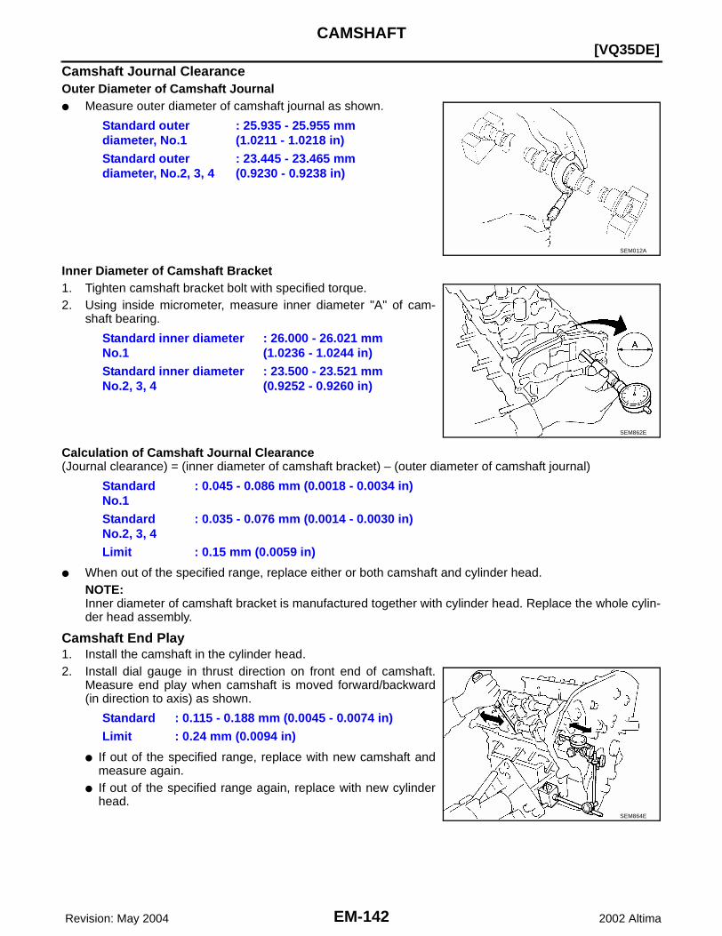
EM-142 Revision: May 2004
[VQ35DE]CAMSHAFT
2002 Altima
Camshaft Journal ClearanceOuter Diameter of Camshaft Journal● Measure outer diameter of camshaft journal as shown.
Inner Diameter of Camshaft Bracket1. Tighten camshaft bracket bolt with specified torque.2. Using inside micrometer, measure inner diameter "A" of cam-
shaft bearing.
Calculation of Camshaft Journal Clearance(Journal clearance) = (inner diameter of camshaft bracket) – (outer diameter of camshaft journal)
● When out of the specified range, replace either or both camshaft and cylinder head.NOTE:Inner diameter of camshaft bracket is manufactured together with cylinder head. Replace the whole cylin-der head assembly.
Camshaft End Play1. Install the camshaft in the cylinder head.2. Install dial gauge in thrust direction on front end of camshaft.
Measure end play when camshaft is moved forward/backward(in direction to axis) as shown.
● If out of the specified range, replace with new camshaft andmeasure again.
● If out of the specified range again, replace with new cylinderhead.
Standard outer diameter, No.1
: 25.935 - 25.955 mm (1.0211 - 1.0218 in)
Standard outer diameter, No.2, 3, 4
: 23.445 - 23.465 mm (0.9230 - 0.9238 in)
SEM012A
Standard inner diameter No.1
: 26.000 - 26.021 mm (1.0236 - 1.0244 in)
Standard inner diameter No.2, 3, 4
: 23.500 - 23.521 mm (0.9252 - 0.9260 in)
SEM862E
Standard No.1
: 0.045 - 0.086 mm (0.0018 - 0.0034 in)
Standard No.2, 3, 4
: 0.035 - 0.076 mm (0.0014 - 0.0030 in)
Limit : 0.15 mm (0.0059 in)
Standard : 0.115 - 0.188 mm (0.0045 - 0.0074 in)Limit : 0.24 mm (0.0094 in)
SEM864E

CAMSHAFT
EM-143
[VQ35DE]
C
D
E
F
G
H
I
J
K
L
M
A
EM
Revision: May 2004 2002 Altima
Camshaft Sprocket Runout1. Install camshaft sprocket on camshaft.2. Measure camshaft sprocket runout.
3. If sprocket runout exceeds the limit, replace camshaft sprocket.
Valve Clearance EBS007Q6
CHECKINGCAUTION:Check valve clearance while engine is cold and not running.1. Remove the air duct with air cleaner case, collectors, hoses, wires, harnesses, and connectors.2. Remove the intake manifold collectors.3. Remove the ignition coils and spark plugs.4. Remove the rocker covers.5. Set No.1 cylinder at TDC on its compression stroke.
● Align pointer with TDC mark on crankshaft pulley.
● Check that the valve lifters on No.1 cylinder are loose andvalve lifters on No.4 are tight. If not, turn the crankshaft onefull revolution (360°) and align as above.
Runout : Less than 0.15 mm (0.0059 in)
SEM865E
SEM727G
SEM418G

EM-144 Revision: May 2004
[VQ35DE]CAMSHAFT
2002 Altima
6. Check only the valves as shown.
● Using a feeler gauge, measure the clearance between thevalve lifter and camshaft.
● Record any valve clearance measurements which are out ofspecification. They will be used later to determine the requiredreplacement lifter size.
7. Turn crankshaft 240° and align as above.8. Set No.3 cylinder at TDC on its compression stroke.
SEM893E
Crank Position Valve No. 1 Valve No. 2 Valve No. 3 Valve No. 6
No. 1 TDC Intake Exhaust Exhaust Intake
SEM139D

CAMSHAFT
EM-145
[VQ35DE]
C
D
E
F
G
H
I
J
K
L
M
A
EM
Revision: May 2004 2002 Altima
9. Check only those valves as shown.
10. Turn the crankshaft 240° and align as above.11. Set No.5 cylinder at TDC on its compression stroke.12. Check only those valves as shown.
SEM894E
Crank Position Valve No. 2 Valve No. 3 Valve No. 4 Valve No. 5
No. 3 TDC Intake Intake Exhaust Exhaust
SEM958E
Crank Position Valve No. 1 Valve No. 4 Valve No. 5 Valve No. 6
No. 5 TDC Exhaust Intake Intake Exhaust
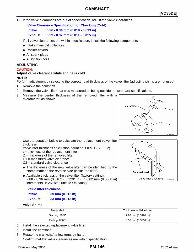
EM-146 Revision: May 2004
[VQ35DE]CAMSHAFT
2002 Altima
13. If the valve clearances are out of specification, adjust the valve clearances.
If all valve clearances are within specification, install the following components:● Intake manifold collectors● Rocker covers● All spark plugs● All ignition coils
ADJUSTINGCAUTION:Adjust valve clearance while engine is cold.NOTE:Perform adjustment by selecting the correct head thickness of the valve lifter (adjusting shims are not used).1. Remove the camshaft.2. Remove the valve lifter that was measured as being outside the standard specifications.3. Measure the center thickness of the removed lifter with a
micrometer, as shown.
4. Use the equation below to calculate the replacement valve lifterthickness.Valve lifter thickness calculation equation: t = t1 + (C1 - C2)t = thickness of the replacement liftert1 = thickness of the removed lifterC1 = measured valve clearanceC2 = standard valve clearance● The thickness of the new valve lifter can be identified by the
stamp mark on the reverse side (inside the lifter).● Available thickness of the valve lifter (factory setting):
7.88 - 8.36 mm (0.3102 - 0.3291 in), in 0.02 mm (0.0008 in)increments, in 25 sizes (intake / exhaust).
Valve Shims
5. Install the selected replacement valve lifter.6. Install the camshaft.7. Rotate the crankshaft a few turns by hand.8. Confirm that the valve clearances are within specification.
Valve Clearance Specification for Checking (Cold)Intake : 0.26 - 0.34 mm (0.010 - 0.013 in)Exhaust : 0.29 - 0.37 mm (0.011 - 0.015 in)
SEM754G
Value lifter thickness:Intake : 0.30 mm (0.012 in)Exhaust : 0.33 mm (0.013 in)
SEM755G
Stamp Mark Thickness of Valve Lifter
Starting: 788C 7.88 mm (0.3102 in)
Ending: 836C 8.36 mm (0.3291 in)
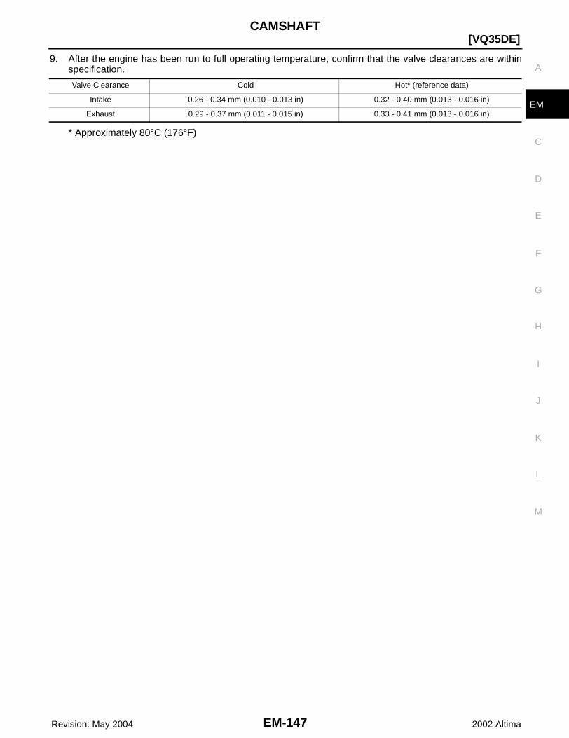
CAMSHAFT
EM-147
[VQ35DE]
C
D
E
F
G
H
I
J
K
L
M
A
EM
Revision: May 2004 2002 Altima
9. After the engine has been run to full operating temperature, confirm that the valve clearances are withinspecification.
* Approximately 80°C (176°F)
Valve Clearance Cold Hot* (reference data)
Intake 0.26 - 0.34 mm (0.010 - 0.013 in) 0.32 - 0.40 mm (0.013 - 0.016 in)
Exhaust 0.29 - 0.37 mm (0.011 - 0.015 in) 0.33 - 0.41 mm (0.013 - 0.016 in)

EM-148 Revision: May 2004
[VQ35DE]TIMING CHAIN
2002 Altima
TIMING CHAIN PFP:13028
Components EBS007Q7
SEM719G

TIMING CHAIN
EM-149
[VQ35DE]
C
D
E
F
G
H
I
J
K
L
M
A
EM
Revision: May 2004 2002 Altima
1. Timing chain tensioner 2. Internal chain guide 3. Timing chain tensioner
4. Camshaft sprocket (EXH) 5. Timing chain (secondary) 6. Timing chain (primary)
7. Camshaft sprocket (INT) 8. Camshaft sprocket (EXH) 9. Timing chain (secondary)
10. Camshaft sprocket (INT) 11. Slack guide 12. Crankshaft sprocket
13. Timing chain tensioner 14. IVTC valve cover 15. Chain tensioner cover
16. RH engine mounting bracket 17. Water hose clamp 18. Water pump cover
19. IVTC valve cover 20. Front oil seal 21. Crankshaft pulley
22. Idler pulley 23. Idler pulley bracket 24. Front timing chain case
25. Rear timing chain case 26. Water drain plug 27. Tension guide
28. O-ring

EM-150 Revision: May 2004
[VQ35DE]TIMING CHAIN
2002 Altima
POSITION FOR APPLYING LIQUID GASKET
● Refer to EM-104, "Precautions for Liquid Gasket" .● Before installation, wipe off any protruding sealant.CAUTION:● After removing timing chain, do not turn the crankshaft and camshaft separately, or the valves will
strike the pistons.● When installing camshafts, chain tensioners, oil seals, or other sliding parts, lubricate contacting
surfaces with new engine oil.
SEM411G

TIMING CHAIN
EM-151
[VQ35DE]
C
D
E
F
G
H
I
J
K
L
M
A
EM
Revision: May 2004 2002 Altima
● Apply new engine oil to bolt threads and seat surfaces when installing camshaft sprockets, cam-shaft brackets, and crankshaft pulley.
● Before disconnecting fuel hose, release fuel pressure. Refer to EC-670, "FUEL PRESSURERELEASE" .
● Before removing the upper oil pan, remove the crankshaft position sensor (POS).● Be careful not to damage sensor edges.● Do not spill engine oil or coolant on drive belts.
Removal EBS007Q8
1. Release the fuel pressure.Refer to EC-670, "FUEL PRESSURE RELEASE" .
2. Remove the battery.3. Drain the engine cooling system.
Refer to EC-1108, "Description" .4. Drain engine oil.
Refer to MA-24, "Changing Engine Oil" .5. Remove engine cover with power tool.6. Remove the intake air duct with the air cleaner case lid and mass air flow sensor.7. Remove the engine coolant reservoir.8. Disconnect the fuel rail quick connector at the vehicle piping side.
Refer to EM-131, "Removal and Installation" .9. Remove the cowl top grille and the windshield wiper assembly.
Refer to EI-18, "Removal and Installation" .10. Remove the front RH wheel and tire with power tool.11. Remove the engine undercovers with power tool.12. Remove the inner fender splash shield with power tool.13. Remove the drive belts and idler pulley.14. Recover the A/C system R134a and remove the A/C compressor.
Refer to MTC-16, "REFRIGERATION SYSTEM" .15. Dismount the power steering oil pump and reservoir tank. Tie them down with wire to reposition them out
of the way.16. Remove the lower and upper oil pans.
Refer to EM-122, "Removal and Installation" .17. Remove the A/C high pressure line.
Refer to MTC-79, "REFRIGERANT LINES" .18. Remove the alternator.
Refer to SC-34, "Removal and Installation" .19. Disconnect the engine harness and set aside.20. Support the engine and remove the RH engine mount and bracket.21. Remove the IVTC valve covers, bank 1 and bank 2. Loosen the
bolts in the numerical order as shown.NOTE:The shaft in the cover is inserted into the center hole of theintake camshaft sprocket. Remove the cover by pulling straightout until the cover disengages from the camshaft sprocket.
22. Remove the starter motor. Refer to SC-23, "Removal and Instal-lation" .
SEM423G
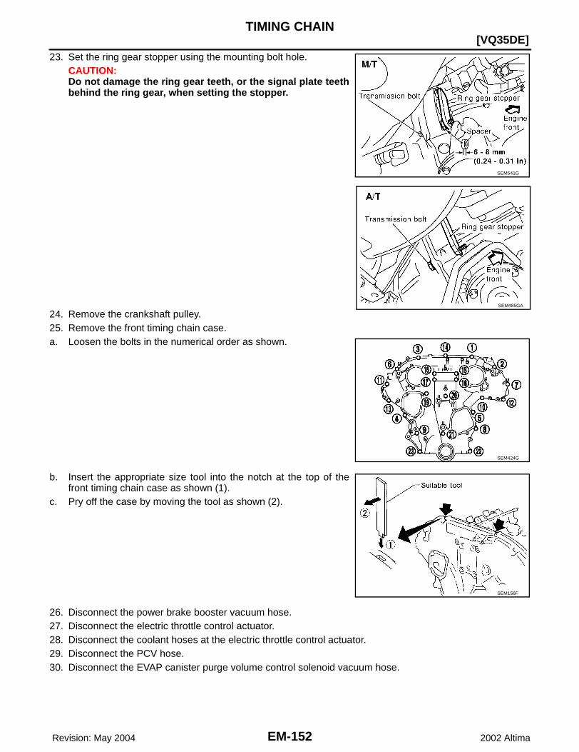
EM-152 Revision: May 2004
[VQ35DE]TIMING CHAIN
2002 Altima
23. Set the ring gear stopper using the mounting bolt hole. CAUTION:Do not damage the ring gear teeth, or the signal plate teethbehind the ring gear, when setting the stopper.
24. Remove the crankshaft pulley.25. Remove the front timing chain case.a. Loosen the bolts in the numerical order as shown.
b. Insert the appropriate size tool into the notch at the top of thefront timing chain case as shown (1).
c. Pry off the case by moving the tool as shown (2).
26. Disconnect the power brake booster vacuum hose.27. Disconnect the electric throttle control actuator.28. Disconnect the coolant hoses at the electric throttle control actuator.29. Disconnect the PCV hose.30. Disconnect the EVAP canister purge volume control solenoid vacuum hose.
SEM541G
SEM485GA
SEM424G
SEM156F
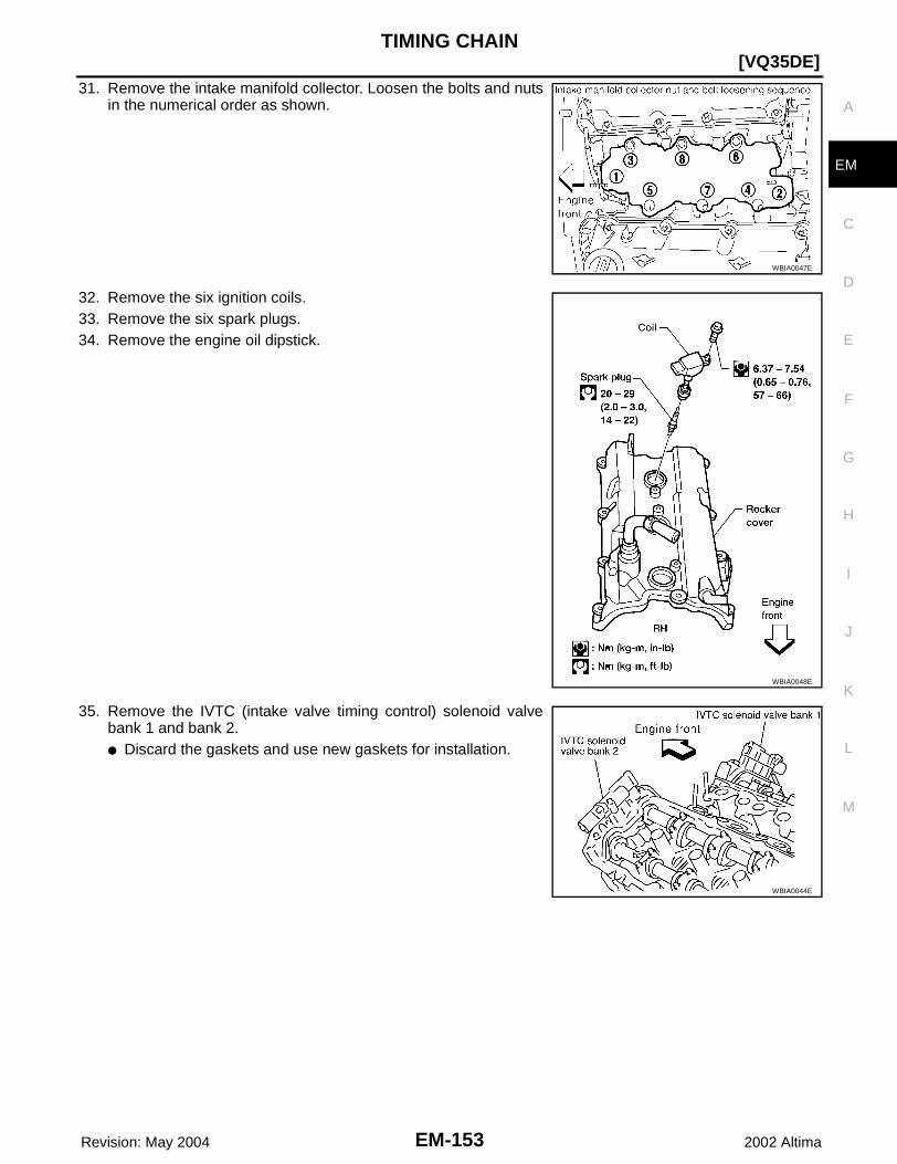
TIMING CHAIN
EM-153
[VQ35DE]
C
D
E
F
G
H
I
J
K
L
M
A
EM
Revision: May 2004 2002 Altima
31. Remove the intake manifold collector. Loosen the bolts and nutsin the numerical order as shown.
32. Remove the six ignition coils.33. Remove the six spark plugs.34. Remove the engine oil dipstick.
35. Remove the IVTC (intake valve timing control) solenoid valvebank 1 and bank 2.● Discard the gaskets and use new gaskets for installation.
WBIA0047E
WBIA0048E
WBIA0044E
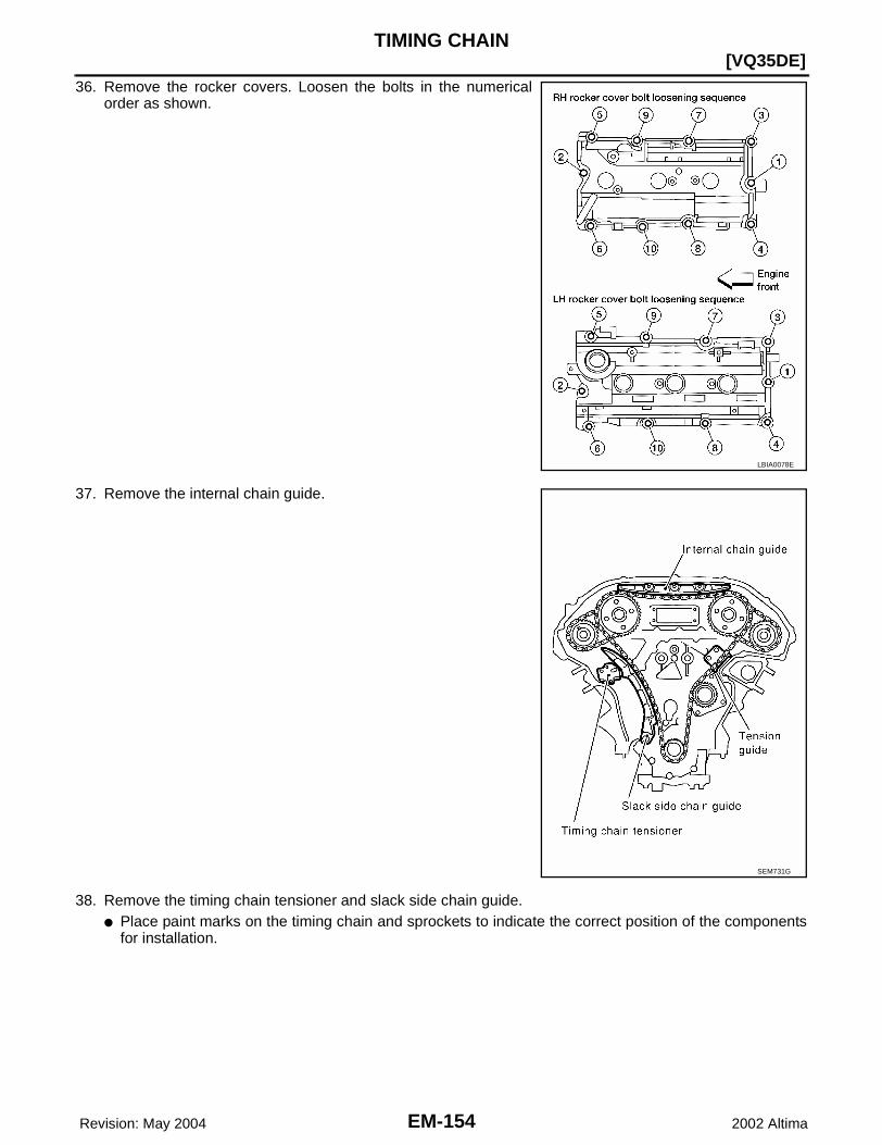
EM-154 Revision: May 2004
[VQ35DE]TIMING CHAIN
2002 Altima
36. Remove the rocker covers. Loosen the bolts in the numericalorder as shown.
37. Remove the internal chain guide.
38. Remove the timing chain tensioner and slack side chain guide.● Place paint marks on the timing chain and sprockets to indicate the correct position of the components
for installation.
LBIA0078E
SEM731G

TIMING CHAIN
EM-155
[VQ35DE]
C
D
E
F
G
H
I
J
K
L
M
A
EM
Revision: May 2004 2002 Altima
a. Pull lever down and release plunger stopper tab. Plunger stop-per tab can be pushed up to release (coaxial structure withlever).
b. Insert stopper pin into tensioner body hole to hold lever, andkeep the tab released. An Allen wrench [2.5 mm (0.098 in)] isused for a stopper pin as an example.
c. Insert plunger into tensioner body by pressing the slack sidechain guide.
d. Keep the slack side chain guide pressed and hold it by pushingthe stopper pin through the lever hole and body hole.
e. Remove the mounting bolts and remove the timing chain ten-sioner.
39. Attach a suitable stopper pin to the RH and LH camshaft chaintensioners (for secondary timing chains).
40. Remove the intake and exhaust camshaft sprocket bolts.● Apply paint to the timing chain and camshaft sprockets for
alignment during installation.● Secure the hexagonal portion of the camshaft using a wrench
to loosen the mounting bolts.
41. Remove the primary and secondary timing chains with camshaftsprockets.● Intake camshaft sprocket is two-for-one structure of primary
and secondary sprockets.● Handle the intake sprockets as an assembly.CAUTION:● Avoid impact or dropping the intake sprockets.● Do not disassemble the intake sprockets (never loosen
bolts A and B as shown).
SEM732G
SEM733G
SEM810G
SEM426G
SEM734G

EM-156 Revision: May 2004
[VQ35DE]TIMING CHAIN
2002 Altima
42. Remove the chain tension guide and crankshaft sprocket.43. Remove the rear timing chain case.
CAUTION:● Do not remove the metal plate cover for the oil passage.● After removing the chain case, do not apply any load to
the case that might bend it.
a. Loosen and remove the mounting bolts in the order shown.b. Cut the sealant with an appropriate tool and remove the rear
timing chain case.
44. Use a scraper to remove all of the old RTV Silicone Sealant fromthe front timing chain case.CAUTION:Do not damage the mating surfaces.
45. Remove all old RTV Silicone Sealant from all the bolt holes andbolts. CAUTION:Do not damage the threads or mating surfaces.
SEM736G
WBIA0078E
SEM428G
SEM161F
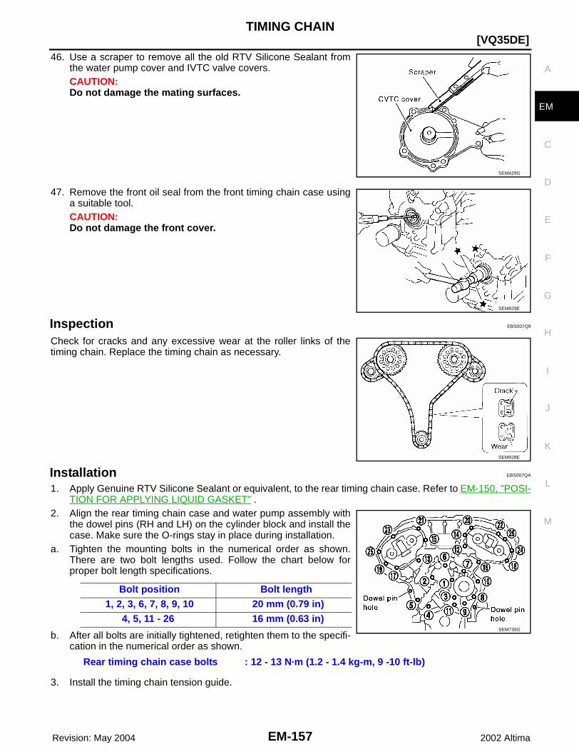
TIMING CHAIN
EM-157
[VQ35DE]
C
D
E
F
G
H
I
J
K
L
M
A
EM
Revision: May 2004 2002 Altima
46. Use a scraper to remove all the old RTV Silicone Sealant fromthe water pump cover and IVTC valve covers.CAUTION:Do not damage the mating surfaces.
47. Remove the front oil seal from the front timing chain case usinga suitable tool.CAUTION:Do not damage the front cover.
Inspection EBS007Q9
Check for cracks and any excessive wear at the roller links of thetiming chain. Replace the timing chain as necessary.
Installation EBS007QA
1. Apply Genuine RTV Silicone Sealant or equivalent, to the rear timing chain case. Refer to EM-150, "POSI-TION FOR APPLYING LIQUID GASKET" .
2. Align the rear timing chain case and water pump assembly withthe dowel pins (RH and LH) on the cylinder block and install thecase. Make sure the O-rings stay in place during installation.
a. Tighten the mounting bolts in the numerical order as shown.There are two bolt lengths used. Follow the chart below forproper bolt length specifications.
b. After all bolts are initially tightened, retighten them to the specifi-cation in the numerical order as shown.
3. Install the timing chain tension guide.
SEM429G
SEM829E
SEM928E
Bolt position Bolt length 1, 2, 3, 6, 7, 8, 9, 10 20 mm (0.79 in) 4, 5, 11 - 26 16 mm (0.63 in)
Rear timing chain case bolts : 12 - 13 N·m (1.2 - 1.4 kg-m, 9 -10 ft-lb)
SEM735G

EM-158 Revision: May 2004
[VQ35DE]TIMING CHAIN
2002 Altima
4. Position the crankshaft so No. 1 piston is set at TDC on thecompression stroke.● Make sure that the dowel pin hole, dowel pin and crankshaft
key are located as shown. Camshaft dowel pin hole (intake side): at cylinder head upperface side in each bank.Camshaft dowel pin (exhaust side): at cylinder head upperface side in each bank.Crankshaft key: at cylinder head side of RH bank.
CAUTION:Hole on small diameter side must be used for intake dowelpin. Do not misidentify (ignore big diameter side).
5. Install the crankshaft sprocket on the crankshaft.● Make sure the mating marks on the crankshaft sprocket face
the front of the engine.
6. Install the secondary timing chains and camshaft sprockets.CAUTION:Matching marks between the timing chain and sprocketsslip easily. Confirm all matching mark positions repeatedlyduring the installation process.
SEM930E
SEM929E
SEM430G

TIMING CHAIN
EM-159
[VQ35DE]
C
D
E
F
G
H
I
J
K
L
M
A
EM
Revision: May 2004 2002 Altima
● Push the sleeve of the secondary chain tensioner and keep itpressed in with a stopper pin.
a. Align the matching marks on the secondary timing chain (goldlink) with the ones on the intake and exhaust sprockets(stamped), and install them.● Matching marks for the intake sprocket are on the back side
of the secondary sprocket.● There are two types of matching marks, round and oval types.
They should be used for the RH and LH banks, respectively.RH bank: use round type.LH bank: use oval type.
b. Align the knock pin and pin hole on the camshaft with the grooveand knock pin on the sprocket, and install them.● On the intake side, align the pin hole on the small diameter
side of the camshaft front end with the knock pin on the backside of the camshaft sprocket, and install them.
● On the exhaust side, align the knock pin on the camshaft frontend with the pin groove on the camshaft sprocket, and installthem.
● Mounting bolts for the camshaft sprockets must be tightenedin the next step. Tightening them by hand is enough to pre-vent the dislocation of the knock pins.
● It may be difficult to visually check the dislocation of matingmarks during and after installation. To make the matchingeasier, make a mating mark on the sprocket teeth in advancewith paint.
7. Install the secondary timing chain and sprocket to the otherbank. Install the primary timing chain at the same time.● Installation of the secondary timing chain follows the proce-
dure in step 6.● Install primary timing chain so the mating mark (punched) on
camshaft sprocket is aligned with the yellow link on the timingchain, while the mating mark (notched) on the crankshaftsprocket is aligned with the orange one on the timing chain,as shown.
● When it is difficult to align mating marks of the primary timingchain with each sprocket, gradually turn the camshaft using awrench on the hexagonal portion to align it with the matingmarks.
● During alignment, be careful to prevent dislocation of matingmark alignments of the secondary timing chains.
SEM738G
SEM811G
SEM739G

EM-160 Revision: May 2004
[VQ35DE]TIMING CHAIN
2002 Altima
8. After confirming the mating marks are aligned, tighten the cam-shaft sprocket mounting bolts.● Secure the camshaft using a wrench at the hexagonal portion
to tighten the mounting bolts.
9. Pull the stopper pins out from the secondary timing chain ten-sioners.
10. Install the internal chain guide.
11. Install the slack guide.● Do not overtighten the slack guide mounting bolts. It is normal
for a gap to exist under the bolt seats when the mounting boltsare tightened to specification.
SEM426G
SEM810G
SEM740G
SEM741G

TIMING CHAIN
EM-161
[VQ35DE]
C
D
E
F
G
H
I
J
K
L
M
A
EM
Revision: May 2004 2002 Altima
12. Install the timing chain tensioner for the slack guide.● When installing the chain tensioner, push in the sleeve and
keep it pressed in with the stopper pin.● Remove any dirt and foreign materials completely from the
back and the mounting surfaces of the chain tensioner.● After installation, pull out the stopper pin by pressing the slack
guide.13. Reconfirm that the matching marks on the sprockets and the
timing chain have not slipped out of alignment.
14. Install new O-rings on the rear timing chain case.
15. Install the front oil seal on the front timing chain case using asuitable tool. Apply clean engine oil to the oil seal edges.
16. Apply liquid gasket to front timing chain case.Refer to EM-150, "POSITION FOR APPLYING LIQUID GASKET" .● Before installation, wipe off the protruding sealant.
SEM733G
SEM435G
SEM715A
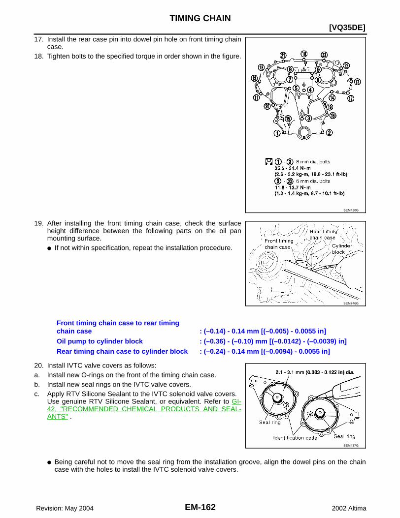
EM-162 Revision: May 2004
[VQ35DE]TIMING CHAIN
2002 Altima
17. Install the rear case pin into dowel pin hole on front timing chaincase.
18. Tighten bolts to the specified torque in order shown in the figure.
19. After installing the front timing chain case, check the surfaceheight difference between the following parts on the oil panmounting surface.● If not within specification, repeat the installation procedure.
20. Install IVTC valve covers as follows:a. Install new O-rings on the front of the timing chain case.b. Install new seal rings on the IVTC valve covers.c. Apply RTV Silicone Sealant to the IVTC solenoid valve covers.
Use genuine RTV Silicone Sealant, or equivalent. Refer to GI-42, "RECOMMENDED CHEMICAL PRODUCTS AND SEAL-ANTS" .
● Being careful not to move the seal ring from the installation groove, align the dowel pins on the chaincase with the holes to install the IVTC solenoid valve covers.
SEM436G
SEM746G
Front timing chain case to rear timing chain case : (–0.14) - 0.14 mm [(–0.005) - 0.0055 in]Oil pump to cylinder block : (–0.36) - (–0.10) mm [(–0.0142) - (–0.0039) in]Rear timing chain case to cylinder block : (–0.24) - 0.14 mm [(–0.0094) - 0.0055 in]
SEM437G

TIMING CHAIN
EM-163
[VQ35DE]
C
D
E
F
G
H
I
J
K
L
M
A
EM
Revision: May 2004 2002 Altima
● Tighten in the numerical order as shown.
21. Install the water pump cover and the chain tensioner cover.Apply RTV Silicone Sealant or equivalent. Refer to GI-42, "REC-OMMENDED CHEMICAL PRODUCTS AND SEALANTS" .
22. Install the RH and LH rocker covers.● Tighten the rocker cover bolts in two stages in the numerical
order as shown.
23. Install the IVTC solenoid valve bank 1 and bank 2.
24. Install the engine oil dipstick.
SEM728G
SEM744G
Stage 1 : 0.96 - 2.96 N·m (0.1 - 0.3 kg-m, 9 - 26 in-lb)Stage 2 : 7.33 - 9.33 N·m (0.75 - 0.95 kg-m, 65 - 82 in-lb)
SEM748G
SEM749G
IVTC solenoid valve bolts
: 10 - 12 N·m (1.0 - 1.3 kg-m, 87 - 112 in-lb)
WBIA0044E

EM-164 Revision: May 2004
[VQ35DE]TIMING CHAIN
2002 Altima
25. Install the six spark plugs to their original positions.
26. Install the six ignition coils to their original positions.
27. Install the intake manifold collector. Tighten the bolts and nuts innumerical order as shown.
28. Connect the EVAP purge volume control solenoid hose.29. Connect the PCV hose.30. Connect the coolant hoses to the electric throttle control actua-
tor.31. Connect the power brake booster vacuum hose.32. Connect the electric throttle control actuator harness electrical
connector.
33. Install crankshaft pulley and tighten the bolt in two stages.● Lubricate thread and seat surface of the bolt with new engine
oil.
Spark plugs (6) : 20 - 29 N·m (2.0 - 3.0 kg-m, 14 - 22 ft-lb)
Ignition coils (6) : 6.37 - 7.54 N·m (0.65 - 0.76 kg-m, 57 - 66 in-lb)
WBIA0048E
Intake manifold collector bolts
: 18 - 21 N·m (1.8 - 2.2 kg-lb, 13 - 15 ft-lb)
WBIA0049E
SEM531G

TIMING CHAIN
EM-165
[VQ35DE]
C
D
E
F
G
H
I
J
K
L
M
A
EM
Revision: May 2004 2002 Altima
● Apply a paint mark for the second stage of angle tightening.
34. Remove the ring gear stopper.35. Install the starter motor. Refer to SC-23, "Removal and Installation" .36. Install the RH engine mount and bracket.
37. Reposition and reconnect the engine harness.38. Install the alternator.
Refer to SC-34, "Removal and Installation" .39. Install the upper and lower oil pans.
Refer to EM-122, "Removal and Installation" .40. Install the power steering pump.
Refer to PS-20, "Removal and Installation" .41. Install the A/C compressor and recharge the system.
Refer to ATC-122, "Removal and Installation for Compressor" .42. Install the idler pulley and the drive belts.
Refer to EM-111, "Checking Drive Belts" .43. Install the inner fender splash shield and the engine undercovers.44. Install the RH wheel and tire.
Refer to WT-4, "WHEEL AND TIRE ASSEMBLY" .45. Install the windshield wiper assembly and the cowl top grille.
Refer to EI-18, "Removal and Installation" .46. Install the fuel hose quick connector to the fuel tube at the vehicle piping side.
Refer to EM-131, "Removal and Installation" .47. Install the engine coolant reservoir.48. Install the intake air duct with the air cleaner case lid and mass air flow sensor.49. Install engine cover.50. Refill the engine with oil and coolant.
Refer to MA-12, "Fluids and Lubricants" .CAUTION:Wait at least 30 minutes for the RTV Silicone Sealant to set before filling the engine with fluids toavoid leaks.
51. Install the battery.52. Activate the fuel system. Check for any leaks when the system is repressurized and correct as necessary.53. Start the engine and check all systems for leaks or improper operation. Correct as necessary.
NOTE:After starting engine, keep idling for three minutes. Then rev engine up to 3,000 rpm under no load topurge air from the high-pressure oil chamber of the chain tensioners. The engine may produce a rattlingnoise. This indicates that air still remains in the chamber and is not a matter of concern.
Stage 1 : 39 - 49 N·m (4.0 - 5.0 kg-m, 29 - 36 ft-lb)Stage 2 : 60° - 65° degrees clockwise
SEM963E
Engine mount to frame bolts (2) : 66 - 74 N·m (6.7 - 7.6 kg-m, 49 - 54 ft-lb)Engine mount bracket to front cover bolts (2) : 79 - 90 N·m (8.0 - 9.2 kg-m, 58 - 66 ft-lb)Engine mount bracket to front cover nut (1) : 10 - 15 N·m (1.0 - 1.6 kg-m, 87 - 138 in-lb)Engine mount to bracket nuts (2) : 49 - 58 N·m (5.0 - 6.0 kg-m, 37 - 43 ft-lb)

EM-166 Revision: May 2004
[VQ35DE]CYLINDER HEAD
2002 Altima
CYLINDER HEAD PFP:11041
On-Vehicle Service EBS007QB
CHECKING COMPRESSION PRESSURE1. Run the engine until it reaches normal operating temperature.2. Turn the ignition switch to OFF.3. Release fuel pressure and leave the fuel pump electrically disconnected.
Refer to EC-670, "FUEL PRESSURE RELEASE" . 4. Remove all six spark plugs.
Refer to EM-129, "Removal and Installation" .5. Attach a compression tester to No. 1 cylinder.6. Depress accelerator pedal fully to keep the electric throttle con-
trol actuator butterfly-valve wide open to maximize air intakeflow.
7. Crank the engine and record the highest gauge indication.8. Repeat the measurement on each cylinder (steps 5 - 7).
● Always use a fully-charged battery to obtain specified enginespeed.
Engine Compression PressureUnit: kPa (kg/cm2 , psi) / rpm
9. If compression in one or more cylinders is low:a. Pour a small amount of engine oil into cylinders through the spark plug holes.b. Retest compression (steps 5 - 8).
● If adding oil helps raise compression pressure, then the piston rings may be worn or damaged. If so,replace piston rings after checking piston.
● If the pressure stays low, a valve may be sticking or is seating improperly. Inspect and repair the valveand/or valve seat. Refer to EM-209, "VALVE" . If the valve and/or valve seat is damaged excessively,replace as necessary.
● If compression stays low in two or more cylinders that are next to each other:– The cylinder head gasket may be leaking.– Both cylinders may have valve component damage. Inspect and repair as necessary.
SEM387C
Standard Minimum Difference limit between cylinders
1,275 (13.0, 185)/300 981 (10.0, 142)/300 98 (1.0, 14)/300

CYLINDER HEAD
EM-167
[VQ35DE]
C
D
E
F
G
H
I
J
K
L
M
A
EM
Revision: May 2004 2002 Altima
Removal and Installation EBS007QC
REMOVAL1. Remove the timing chains. Refer to EM-151, "Removal" .2. Remove the fuel rail and injectors. Refer to EM-131, "Removal and Installation" .
SEM752G
1. Oil filler cap 2. Oil catcher 3. Rocker cover
4. PCV hose 5. IVTC solenoid valve 6. PCV valve
7. Chain tensioner 8. Spring 9. Tensioner sleeve
10. Valve 11. Cylinder head 12. Camshaft position sensor (PHASE)
13. Spark plug 14. Valve spring seat 15. Valve spring
16. Valve spring retainer 17. Valve collet 18. Valve lifter
19. Camshaft (EXH) 20. Camshaft (INT) 21. Camshaft bracket

EM-168 Revision: May 2004
[VQ35DE]CYLINDER HEAD
2002 Altima
3. Remove the intake manifold using power tool.● Loosen the bolts in the numerical order as shown.
4. Remove the coolant outlet housing.
5. Remove rear timing chain case bolts using power tool.● Loosen the bolts in the numerical order as shown.
6. Remove rear timing chain case using the Tool.
7. Remove the O-rings from the front of the cylinder heads.● Discard the O-rings and use new O-rings for installation.
8. Remove the O-rings from the cylinder block.● Discard the O-rings and use new O-rings for installation.
WBIA0043E
SEM442G
SEM279G
SEM447G
SEM534G

CYLINDER HEAD
EM-169
[VQ35DE]
C
D
E
F
G
H
I
J
K
L
M
A
EM
Revision: May 2004 2002 Altima
9. Remove the IVTC (intake valve timing control) valves.● Discard the IVTC valve gaskets and use new gaskets for
installation.
10. Remove the intake and exhaust camshafts and the camshaftbrackets.● Mark the camshaft brackets so they are placed in the same
position and direction for installation.● Equally loosen the camshaft bracket bolts in several steps in
the numerical order shown.
NOTE:If replacing the oil seals only, without removing the cylinder head, follow the steps below. Use method A orMethod B to hold the valve in place while removing the component parts, so the valve does not fall into thecombustion chamber.
a. Method A:Without removing the cylinder head, set the piston being worked on to TDC to prevent the valve from fall-ing into the combustion chamber.Method B:Without removing the cylinder head, remove the spark plug fromthe head, then install an air hose adapter into the spark plughole and apply air pressure of 490 kPa (5 kg/cm2, 71 psi), asshown. The air pressure will hold the valve in place. Thismethod will only work if the valves and valve seats are in goodcondition, if not, use Method A.
b. Remove the valve lifters. Mark the lifters so they are installed in their original position if being reused.
WBIA0044E
SEM856E
SEM857E
SEM826E

EM-170 Revision: May 2004
[VQ35DE]CYLINDER HEAD
2002 Altima
c. Compress the valve spring with the Tool and remove the follow-ing components:● Valve collet● Valve spring retainer● Valve spring● Valve spring seat
d. With suitable pliers, remove the valve oil seal and replace it.
11. Remove the RH and LH cylinder head bolts, with power tool.● The bolts should be loosened gradually in three stages.● Loosen the bolts in the numerical order as shown.
12. Remove cylinder heads and gaskets.● Discard the cylinder head gaskets and use new gaskets for
installation.
SEM948E
SEM827E
SEM859E
SEM860E
SEM863E
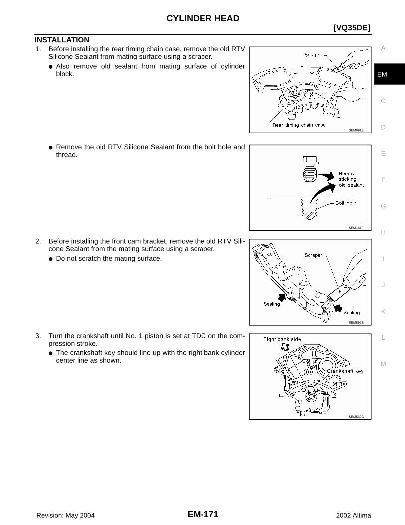
CYLINDER HEAD
EM-171
[VQ35DE]
C
D
E
F
G
H
I
J
K
L
M
A
EM
Revision: May 2004 2002 Altima
INSTALLATION1. Before installing the rear timing chain case, remove the old RTV
Silicone Sealant from mating surface using a scraper.● Also remove old sealant from mating surface of cylinder
block.
● Remove the old RTV Silicone Sealant from the bolt hole andthread.
2. Before installing the front cam bracket, remove the old RTV Sili-cone Sealant from the mating surface using a scraper.● Do not scratch the mating surface.
3. Turn the crankshaft until No. 1 piston is set at TDC on the com-pression stroke.● The crankshaft key should line up with the right bank cylinder
center line as shown.
SEM891E
SEM161F
SEM892E
SEM532G
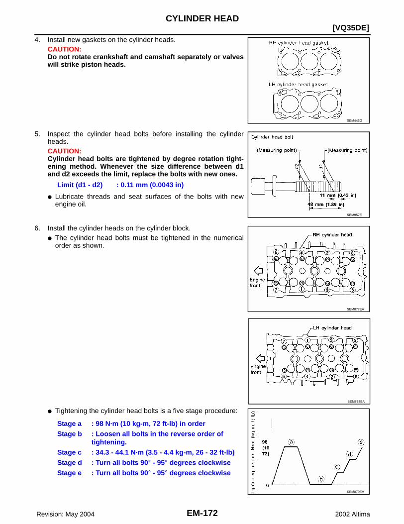
EM-172 Revision: May 2004
[VQ35DE]CYLINDER HEAD
2002 Altima
4. Install new gaskets on the cylinder heads.CAUTION:Do not rotate crankshaft and camshaft separately or valveswill strike piston heads.
5. Inspect the cylinder head bolts before installing the cylinderheads.CAUTION:Cylinder head bolts are tightened by degree rotation tight-ening method. Whenever the size difference between d1and d2 exceeds the limit, replace the bolts with new ones.
● Lubricate threads and seat surfaces of the bolts with newengine oil.
6. Install the cylinder heads on the cylinder block.● The cylinder head bolts must be tightened in the numerical
order as shown.
● Tightening the cylinder head bolts is a five stage procedure:
SEM445G
Limit (d1 - d2) : 0.11 mm (0.0043 in)
SEM957E
SEM877EA
SEM878EA
Stage a : 98 N·m (10 kg-m, 72 ft-lb) in orderStage b : Loosen all bolts in the reverse order of
tightening.Stage c : 34.3 - 44.1 N·m (3.5 - 4.4 kg-m, 26 - 32 ft-lb)Stage d : Turn all bolts 90° - 95° degrees clockwiseStage e : Turn all bolts 90° - 95° degrees clockwise
SEM879EA
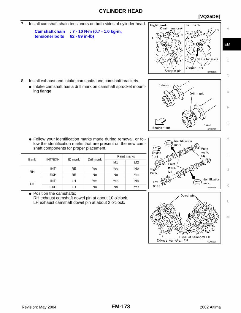
CYLINDER HEAD
EM-173
[VQ35DE]
C
D
E
F
G
H
I
J
K
L
M
A
EM
Revision: May 2004 2002 Altima
7. Install camshaft chain tensioners on both sides of cylinder head.
8. Install exhaust and intake camshafts and camshaft brackets.● Intake camshaft has a drill mark on camshaft sprocket mount-
ing flange.
● Follow your identification marks made during removal, or fol-low the identification marks that are present on the new cam-shaft components for proper placement.
● Position the camshafts:RH exhaust camshaft dowel pin at about 10 o'clock.LH exhaust camshaft dowel pin at about 2 o'clock.
Camshaft chain tensioner bolts
: 7 - 10 N·m (0.7 - 1.0 kg-m,62 - 89 in-lb)
SEM444G
SEM652F
Bank INT/EXH ID mark Drill markPaint marks
M1 M2
RHINT RE Yes Yes No
EXH RE No No Yes
LHINT LH Yes Yes No
EXH LH No No Yes SEM653F
SEM533G

EM-174 Revision: May 2004
[VQ35DE]CYLINDER HEAD
2002 Altima
9. Before installing camshaft brackets, apply sealant to mating sur-face of No. 1 journal head.● Use Genuine RTV Silicone Sealant, or equivalent. Refer to
GI-42, "RECOMMENDED CHEMICAL PRODUCTS ANDSEALANTS" .
● Refer to EM-150, "POSITION FOR APPLYING LIQUID GAS-KET" .
● Install camshaft brackets in their original positions and direc-tion. Align the stamp marks as shown.
● If any part of valve assembly or camshaft is replaced, checkand adjust the valve clearance. Refer to EM-143, "ValveClearance" .
● Lubricate the threads and seat surfaces of the camshaftbracket bolts with new engine oil before installation.
● Tighten the camshaft brackets in the following four steps.
SEM446G
Valve clearance (cold) Intake
: 0.26 - 0.34 mm (0.010 - 0.013 in)
Valve clearance (cold) Exhaust
: 0.29 - 0.37 mm (0.011 - 0.015 in)
SEM564G
Step Tightening torque Tightening order
1 1.96 N·m (0.2 kg-m, 17 in-lb) Tighten No.s 7 to 10, then tighten 1 to 6 in order as shown.
2 6 N·m (0.6 kg-m, 52 in-lb) Tighten in numerical order as shown.
3 9.02 - 11.8 N·m (0.92 - 1.20 kg-m, 79.9 - 104.2 in-lb) Tighten 1 - 6 in numerical order as shown.
4 8.3 - 10.3 N·m (0.9 - 1.0 kg-m, 74 - 91 in-lb) Tighten 7 - 10 in numerical order as shown.
SEM885EA
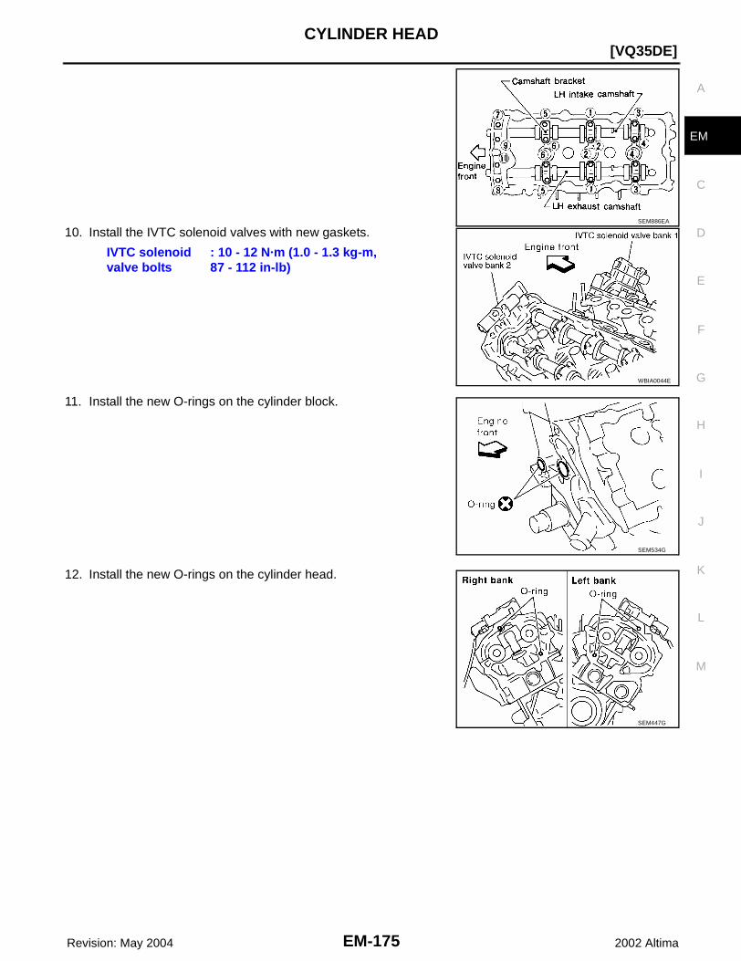
CYLINDER HEAD
EM-175
[VQ35DE]
C
D
E
F
G
H
I
J
K
L
M
A
EM
Revision: May 2004 2002 Altima
10. Install the IVTC solenoid valves with new gaskets.
11. Install the new O-rings on the cylinder block.
12. Install the new O-rings on the cylinder head.
SEM886EA
IVTC solenoid valve bolts
: 10 - 12 N·m (1.0 - 1.3 kg-m,87 - 112 in-lb)
WBIA0044E
SEM534G
SEM447G
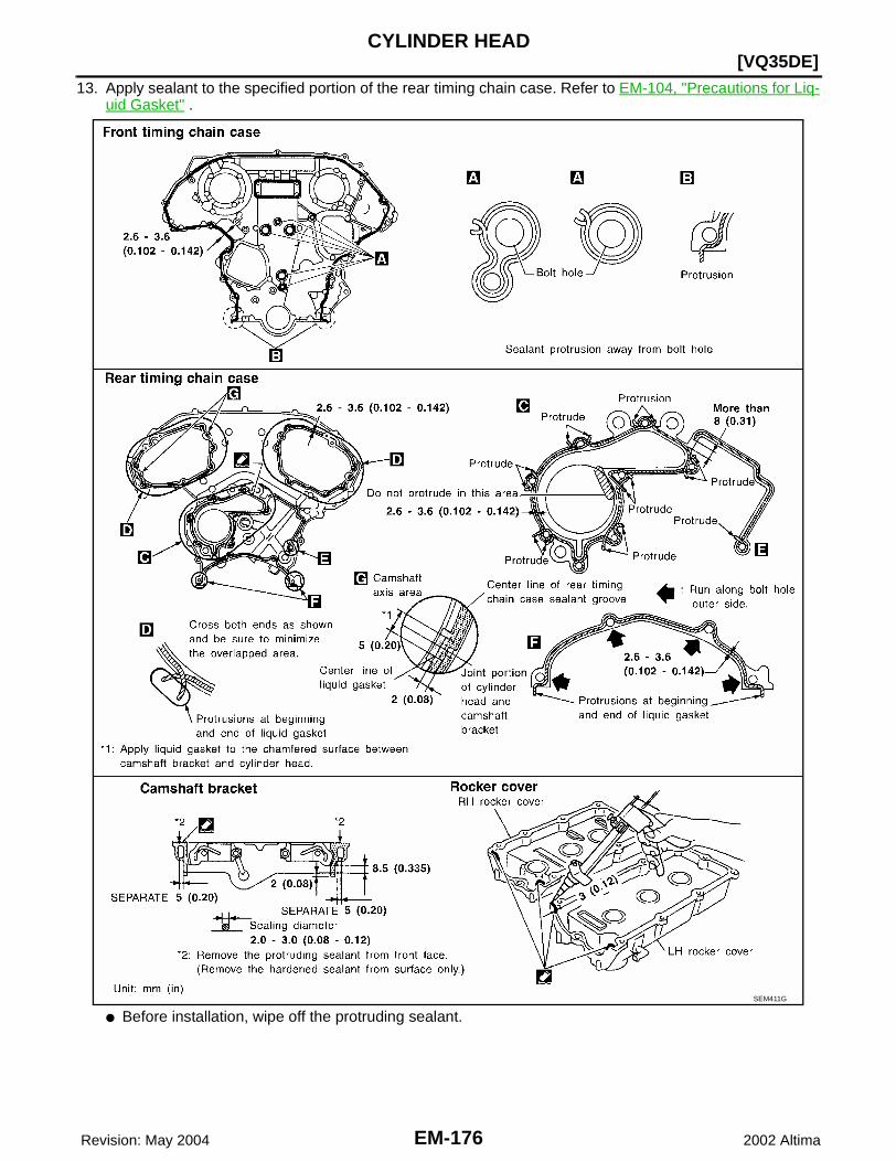
EM-176 Revision: May 2004
[VQ35DE]CYLINDER HEAD
2002 Altima
13. Apply sealant to the specified portion of the rear timing chain case. Refer to EM-104, "Precautions for Liq-uid Gasket" .
● Before installation, wipe off the protruding sealant.SEM411G

CYLINDER HEAD
EM-177
[VQ35DE]
C
D
E
F
G
H
I
J
K
L
M
A
EM
Revision: May 2004 2002 Altima
14. Align rear timing chain case with dowel pins, then install on cyl-inder head and block.
15. Tighten rear chain case bolts in two stages.a. Tighten bolts in numerical order shown.b. Retighten bolts in numerical order shown.
16. Install the coolant outlet housing.17. Install the intake manifold with a new gasket.
● Tighten the bolts in the numerical order as shown.
18. Install the fuel rail and injectors. Refer to EM-131, "Removal and Installation" .19. Install the timing chains. Refer to EM-157, "Installation" .
SEM448G
Stage 1 : 5 - 10 N·m (0.5 - 1.0 kg-m, 44 - 86 in-lb)Stage 2 : 26 - 31 N·m (2.7 - 3.2 kg-m, 20 - 23 ft-lb)
SEM950F
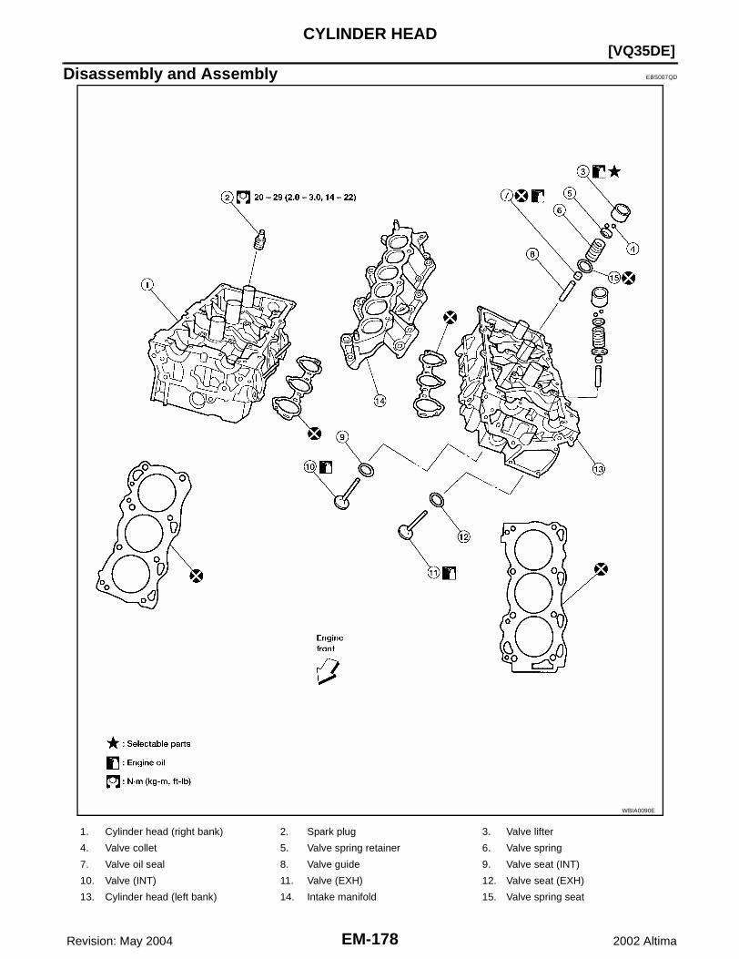
EM-178 Revision: May 2004
[VQ35DE]CYLINDER HEAD
2002 Altima
Disassembly and Assembly EBS007QD
WBIA0090E
1. Cylinder head (right bank) 2. Spark plug 3. Valve lifter
4. Valve collet 5. Valve spring retainer 6. Valve spring
7. Valve oil seal 8. Valve guide 9. Valve seat (INT)
10. Valve (INT) 11. Valve (EXH) 12. Valve seat (EXH)
13. Cylinder head (left bank) 14. Intake manifold 15. Valve spring seat
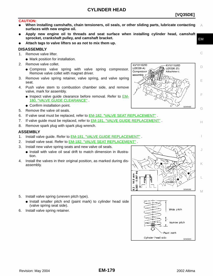
CYLINDER HEAD
EM-179
[VQ35DE]
C
D
E
F
G
H
I
J
K
L
M
A
EM
Revision: May 2004 2002 Altima
CAUTION:● When installing camshafts, chain tensioners, oil seals, or other sliding parts, lubricate contacting
surfaces with new engine oil.● Apply new engine oil to threads and seat surface when installing cylinder head, camshaft
sprocket, crankshaft pulley, and camshaft bracket.● Attach tags to valve lifters so as not to mix them up.
DISASSEMBLY1. Remove valve lifter.
● Mark position for installation.2. Remove valve collet.
● Compress valve spring with valve spring compressor.Remove valve collet with magnet driver.
3. Remove valve spring retainer, valve spring, and valve springseat.
4. Push valve stem to combustion chamber side, and removevalve, mark for assembly. ● Inspect valve guide clearance before removal. Refer to EM-
180, "VALVE GUIDE CLEARANCE" .● Confirm installation point.
5. Remove the valve oil seals.6. If valve seat must be replaced, refer to EM-182, "VALVE SEAT REPLACEMENT" .7. If valve guide must be replaced, refer to EM-181, "VALVE GUIDE REPLACEMENT" .8. Remove spark plug with spark plug wrench.
ASSEMBLY1. Install valve guide. Refer to EM-181, "VALVE GUIDE REPLACEMENT" .2. Install valve seat. Refer to EM-182, "VALVE SEAT REPLACEMENT" .3. Install new valve spring seats and new valve oil seals.
● Install with valve oil seal drift to match dimension in illustra-tion.
4. Install the valves in their original position, as marked during dis-assembly.
5. Install valve spring (uneven pitch type).● Install smaller pitch end (paint mark) to cylinder head side
(valve spring seat side).6. Install valve spring retainer.
SEM948E
SEM828E
SEM085D
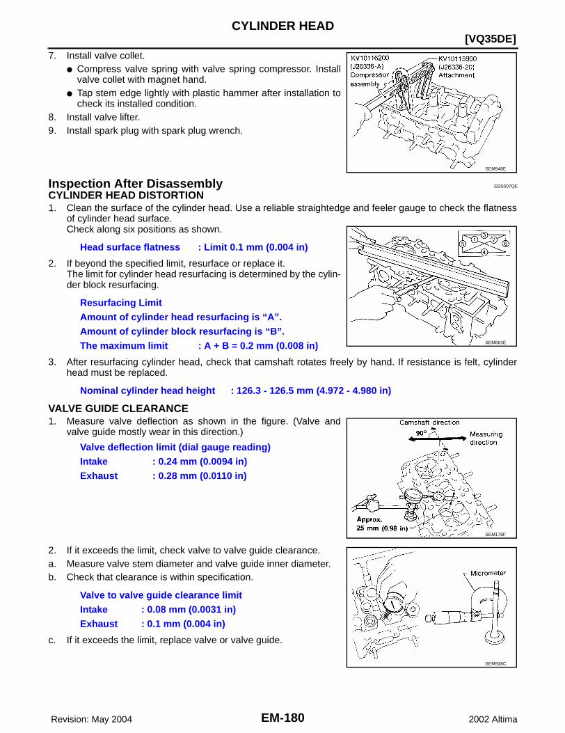
EM-180 Revision: May 2004
[VQ35DE]CYLINDER HEAD
2002 Altima
7. Install valve collet.● Compress valve spring with valve spring compressor. Install
valve collet with magnet hand.● Tap stem edge lightly with plastic hammer after installation to
check its installed condition.8. Install valve lifter.9. Install spark plug with spark plug wrench.
Inspection After Disassembly EBS007QE
CYLINDER HEAD DISTORTION1. Clean the surface of the cylinder head. Use a reliable straightedge and feeler gauge to check the flatness
of cylinder head surface.Check along six positions as shown.
2. If beyond the specified limit, resurface or replace it.The limit for cylinder head resurfacing is determined by the cylin-der block resurfacing.
3. After resurfacing cylinder head, check that camshaft rotates freely by hand. If resistance is felt, cylinderhead must be replaced.
VALVE GUIDE CLEARANCE1. Measure valve deflection as shown in the figure. (Valve and
valve guide mostly wear in this direction.)
2. If it exceeds the limit, check valve to valve guide clearance.a. Measure valve stem diameter and valve guide inner diameter.b. Check that clearance is within specification.
c. If it exceeds the limit, replace valve or valve guide.
SEM948E
Head surface flatness : Limit 0.1 mm (0.004 in)
Resurfacing LimitAmount of cylinder head resurfacing is “A”.Amount of cylinder block resurfacing is “B”.The maximum limit : A + B = 0.2 mm (0.008 in)
Nominal cylinder head height : 126.3 - 126.5 mm (4.972 - 4.980 in)
SEM861E
Valve deflection limit (dial gauge reading)Intake : 0.24 mm (0.0094 in)Exhaust : 0.28 mm (0.0110 in)
SEM178F
Valve to valve guide clearance limitIntake : 0.08 mm (0.0031 in)Exhaust : 0.1 mm (0.004 in)
SEM938C

CYLINDER HEAD
EM-181
[VQ35DE]
C
D
E
F
G
H
I
J
K
L
M
A
EM
Revision: May 2004 2002 Altima
VALVE GUIDE REPLACEMENTCAUTION:When a valve guide is removed, replace it with an oversized [0.2 mm (0.008 in)] valve guide.1. To remove valve guide, heat cylinder head to 110° to 130°C
(230° to 266°F) by soaking in heated oil.
2. Drive out the valve guide with a press [under a 20 kN (2.2 USton) pressure] or hammer and suitable tool.
3. Ream cylinder head valve guide hole.
4. Heat cylinder head to 110° to 130°C (230° to 266°F) by soakingin heated oil and press new valve guide from camshaft side intothe cylinder head to the dimensions as shown.
SEM008A
SEM931C
Valve guide hole diame-ter (for service parts), intake and exhaust
: 10.175 - 10.196 mm (0.4006 - 0.4014 in)
SEM932C
Projection "L" : 12.6 - 12.8 mm (0.496 - 0.504 in)
SEM950E
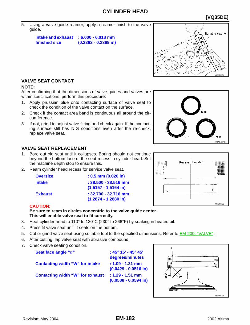
EM-182 Revision: May 2004
[VQ35DE]CYLINDER HEAD
2002 Altima
5. Using a valve guide reamer, apply a reamer finish to the valveguide.
VALVE SEAT CONTACTNOTE:After confirming that the dimensions of valve guides and valves arewithin specifications, perform this procedure. 1. Apply prussian blue onto contacting surface of valve seat to
check the condition of the valve contact on the surface.2. Check if the contact area band is continuous all around the cir-
cumference.3. If not, grind to adjust valve fitting and check again. If the contact-
ing surface still has N.G conditions even after the re-check,replace valve seat.
VALVE SEAT REPLACEMENT1. Bore out old seat until it collapses. Boring should not continue
beyond the bottom face of the seat recess in cylinder head. Setthe machine depth stop to ensure this.
2. Ream cylinder head recess for service valve seat.
CAUTION:Be sure to ream in circles concentric to the valve guide center.This will enable valve seat to fit correctly.
3. Heat cylinder head to 110° to 130°C (230° to 266°F) by soaking in heated oil.4. Press fit valve seat until it seats on the bottom.5. Cut or grind valve seat using suitable tool to the specified dimensions. Refer to EM-209, "VALVE" .6. After cutting, lap valve seat with abrasive compound.7. Check valve seating condition.
Intake and exhaust finished size
: 6.000 - 6.018 mm(0.2362 - 0.2369 in)
SEM932C
EMA0487D
Oversize : 0.5 mm (0.020 in)Intake : 38.500 - 38.516 mm
(1.5157 - 1.5164 in)Exhaust : 32.700 - 32.716 mm
(1.2874 - 1.2880 in)
Seat face angle “α” : 45° 15' - 45° 45' degrees/minutes
Contacting width “W” for intake : 1.09 - 1.31 mm (0.0429 - 0.0516 in)
Contacting width “W” for exhaust : 1.29 - 1.51 mm (0.0508 - 0.0594 in)
SEM795A
SEM892B
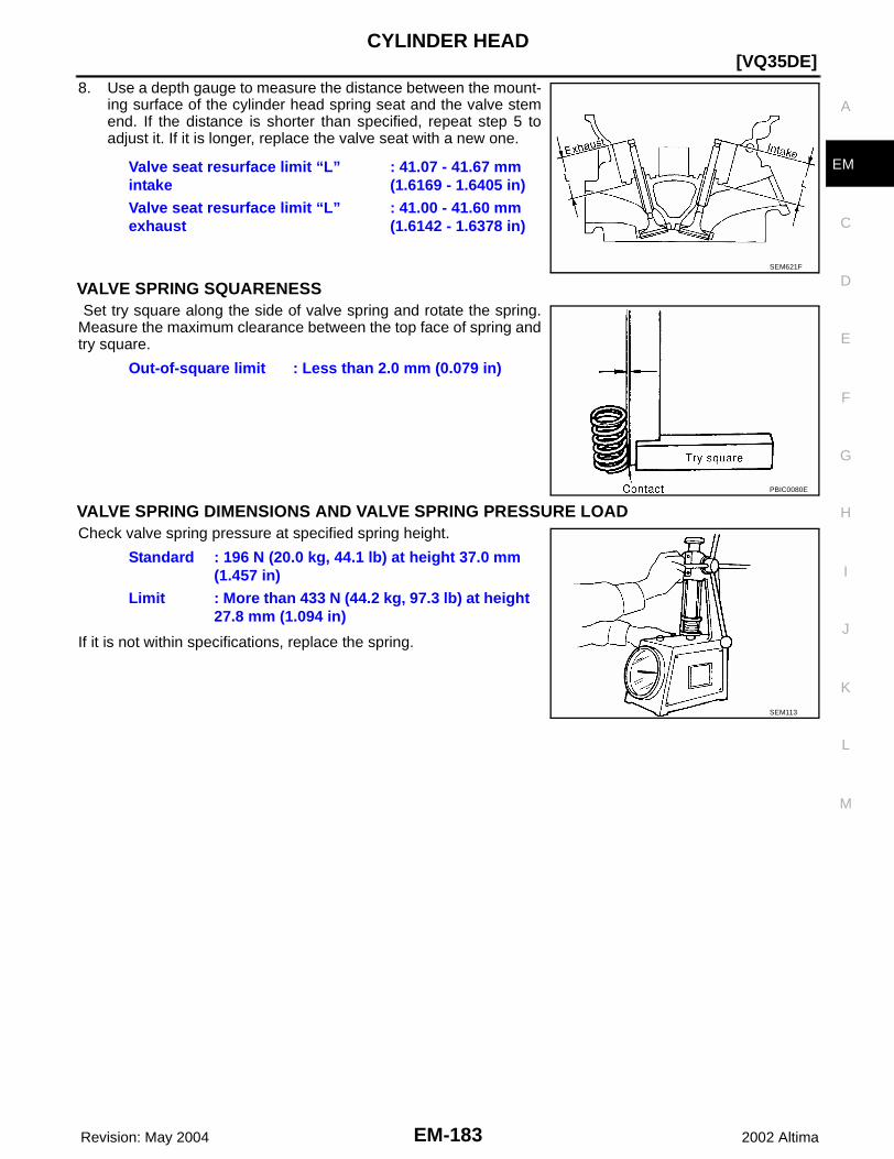
CYLINDER HEAD
EM-183
[VQ35DE]
C
D
E
F
G
H
I
J
K
L
M
A
EM
Revision: May 2004 2002 Altima
8. Use a depth gauge to measure the distance between the mount-ing surface of the cylinder head spring seat and the valve stemend. If the distance is shorter than specified, repeat step 5 toadjust it. If it is longer, replace the valve seat with a new one.
VALVE SPRING SQUARENESS Set try square along the side of valve spring and rotate the spring.Measure the maximum clearance between the top face of spring andtry square.
VALVE SPRING DIMENSIONS AND VALVE SPRING PRESSURE LOADCheck valve spring pressure at specified spring height.
If it is not within specifications, replace the spring.
Valve seat resurface limit “L” intake
: 41.07 - 41.67 mm (1.6169 - 1.6405 in)
Valve seat resurface limit “L” exhaust
: 41.00 - 41.60 mm (1.6142 - 1.6378 in)
SEM621F
Out-of-square limit : Less than 2.0 mm (0.079 in)
PBIC0080E
Standard : 196 N (20.0 kg, 44.1 lb) at height 37.0 mm (1.457 in)
Limit : More than 433 N (44.2 kg, 97.3 lb) at height 27.8 mm (1.094 in)
SEM113

EM-184 Revision: May 2004
[VQ35DE]ENGINE ASSEMBLY
2002 Altima
ENGINE ASSEMBLY PFP:10001
Removal and Installation EBS007QF
WBIA0220E
1. LH transaxle mounting insulator (A/T) 2. LH transaxle mounting bracket (M/T) 3. LH transaxle mounting bracket (M/T)
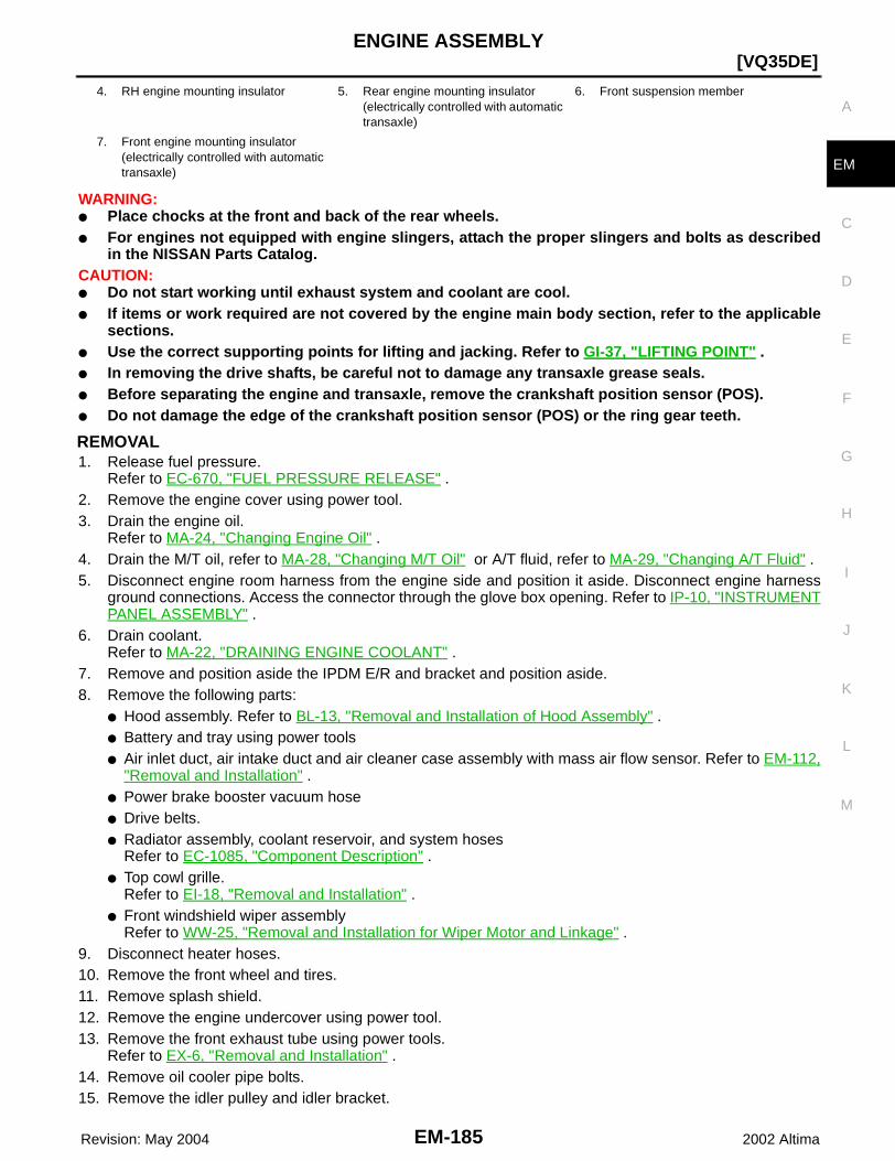
ENGINE ASSEMBLY
EM-185
[VQ35DE]
C
D
E
F
G
H
I
J
K
L
M
A
EM
Revision: May 2004 2002 Altima
WARNING:● Place chocks at the front and back of the rear wheels.● For engines not equipped with engine slingers, attach the proper slingers and bolts as described
in the NISSAN Parts Catalog.CAUTION:● Do not start working until exhaust system and coolant are cool.● If items or work required are not covered by the engine main body section, refer to the applicable
sections.● Use the correct supporting points for lifting and jacking. Refer to GI-37, "LIFTING POINT" .● In removing the drive shafts, be careful not to damage any transaxle grease seals.● Before separating the engine and transaxle, remove the crankshaft position sensor (POS).● Do not damage the edge of the crankshaft position sensor (POS) or the ring gear teeth.
REMOVAL1. Release fuel pressure.
Refer to EC-670, "FUEL PRESSURE RELEASE" .2. Remove the engine cover using power tool.3. Drain the engine oil.
Refer to MA-24, "Changing Engine Oil" .4. Drain the M/T oil, refer to MA-28, "Changing M/T Oil" or A/T fluid, refer to MA-29, "Changing A/T Fluid" .5. Disconnect engine room harness from the engine side and position it aside. Disconnect engine harness
ground connections. Access the connector through the glove box opening. Refer to IP-10, "INSTRUMENTPANEL ASSEMBLY" .
6. Drain coolant.Refer to MA-22, "DRAINING ENGINE COOLANT" .
7. Remove and position aside the IPDM E/R and bracket and position aside.8. Remove the following parts:
● Hood assembly. Refer to BL-13, "Removal and Installation of Hood Assembly" .● Battery and tray using power tools● Air inlet duct, air intake duct and air cleaner case assembly with mass air flow sensor. Refer to EM-112,
"Removal and Installation" .● Power brake booster vacuum hose● Drive belts.● Radiator assembly, coolant reservoir, and system hoses
Refer to EC-1085, "Component Description" .● Top cowl grille.
Refer to EI-18, "Removal and Installation" .● Front windshield wiper assembly
Refer to WW-25, "Removal and Installation for Wiper Motor and Linkage" .9. Disconnect heater hoses.10. Remove the front wheel and tires.11. Remove splash shield.12. Remove the engine undercover using power tool.13. Remove the front exhaust tube using power tools.
Refer to EX-6, "Removal and Installation" .14. Remove oil cooler pipe bolts.15. Remove the idler pulley and idler bracket.
4. RH engine mounting insulator 5. Rear engine mounting insulator (electrically controlled with automatic transaxle)
6. Front suspension member
7. Front engine mounting insulator (electrically controlled with automatic transaxle)
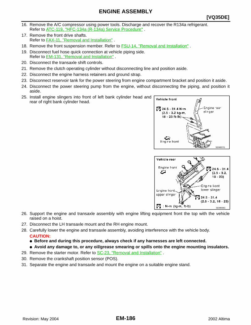
EM-186 Revision: May 2004
[VQ35DE]ENGINE ASSEMBLY
2002 Altima
16. Remove the A/C compressor using power tools. Discharge and recover the R134a refrigerant.Refer to ATC-119, "HFC-134a (R-134a) Service Procedure" .
17. Remove the front drive shafts.Refer to FAX-11, "Removal and Installation" .
18. Remove the front suspension member. Refer to FSU-14, "Removal and Installation" .19. Disconnect fuel hose quick connection at vehicle piping side.
Refer to EM-131, "Removal and Installation" .20. Disconnect the transaxle shift controls.21. Remove the clutch operating cylinder without disconnecting line and position aside.22. Disconnect the engine harness retainers and ground strap.23. Disconnect reservoir tank for the power steering from engine compartment bracket and position it aside.24. Disconnect the power steering pump from the engine, without disconnecting the piping, and position it
aside.25. Install engine slingers into front of left bank cylinder head and
rear of right bank cylinder head.
26. Support the engine and transaxle assembly with engine lifting equipment front the top with the vehicleraised on a hoist.
27. Disconnect the LH transaxle mount and the RH engine mount.28. Carefully lower the engine and transaxle assembly, avoiding interference with the vehicle body.
CAUTION:● Before and during this procedure, always check if any harnesses are left connected.● Avoid any damage to, or any oil/grease smearing or spills onto the engine mounting insulators.
29. Remove the starter motor. Refer to SC-23, "Removal and Installation" .30. Remove the crankshaft position sensor (POS).31. Separate the engine and transaxle and mount the engine on a suitable engine stand.
SEM807G
SEM808G
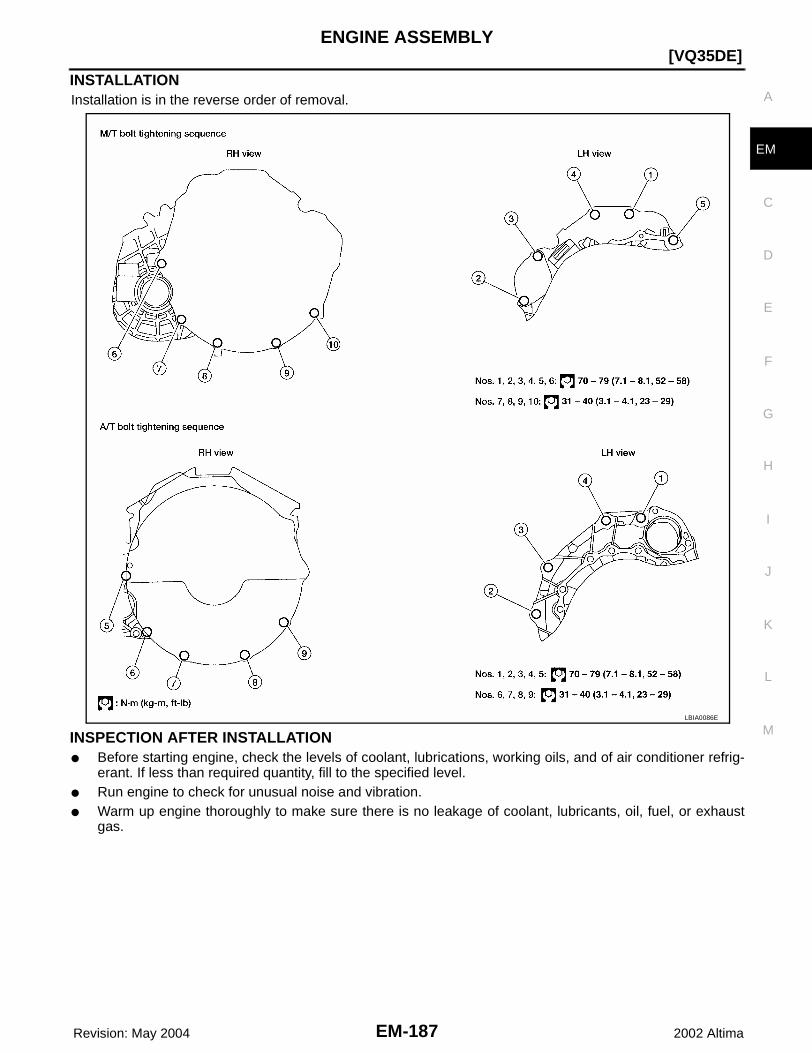
ENGINE ASSEMBLY
EM-187
[VQ35DE]
C
D
E
F
G
H
I
J
K
L
M
A
EM
Revision: May 2004 2002 Altima
INSTALLATIONInstallation is in the reverse order of removal.
INSPECTION AFTER INSTALLATION● Before starting engine, check the levels of coolant, lubrications, working oils, and of air conditioner refrig-
erant. If less than required quantity, fill to the specified level.● Run engine to check for unusual noise and vibration.● Warm up engine thoroughly to make sure there is no leakage of coolant, lubricants, oil, fuel, or exhaust
gas.
LBIA0086E

EM-188 Revision: May 2004
[VQ35DE]CYLINDER BLOCK
2002 Altima
CYLINDER BLOCK PFP:11010
Disassembly and Assembly EBS007QG
WBIA0091E
1. Rear oil seal retainer 2. Cylinder block 3. Knock sensor
4. Upper main bearing 5. Lower main bearing 6. Water drain plug (LH side)
7. Water drain plug (RH side) 8. Water drain plug (water pump side) 9. Main bearing cap
10. Main bearing beam 11. Crankshaft 12. Pilot bushing or pilot converter
13. Flywheel with signal plate (M/T) 14. Drive plate with signal plate (A/T) 15. Flywheel reinforcement
16. Drive plate reinforcement 17. Oil ring set 18. Piston pin
19. Connecting rod bearing 20. Connecting rod 21. Piston
22. Top ring 23. Second ring 24. Cylinder block heater (Canada only)
25. Oil jet
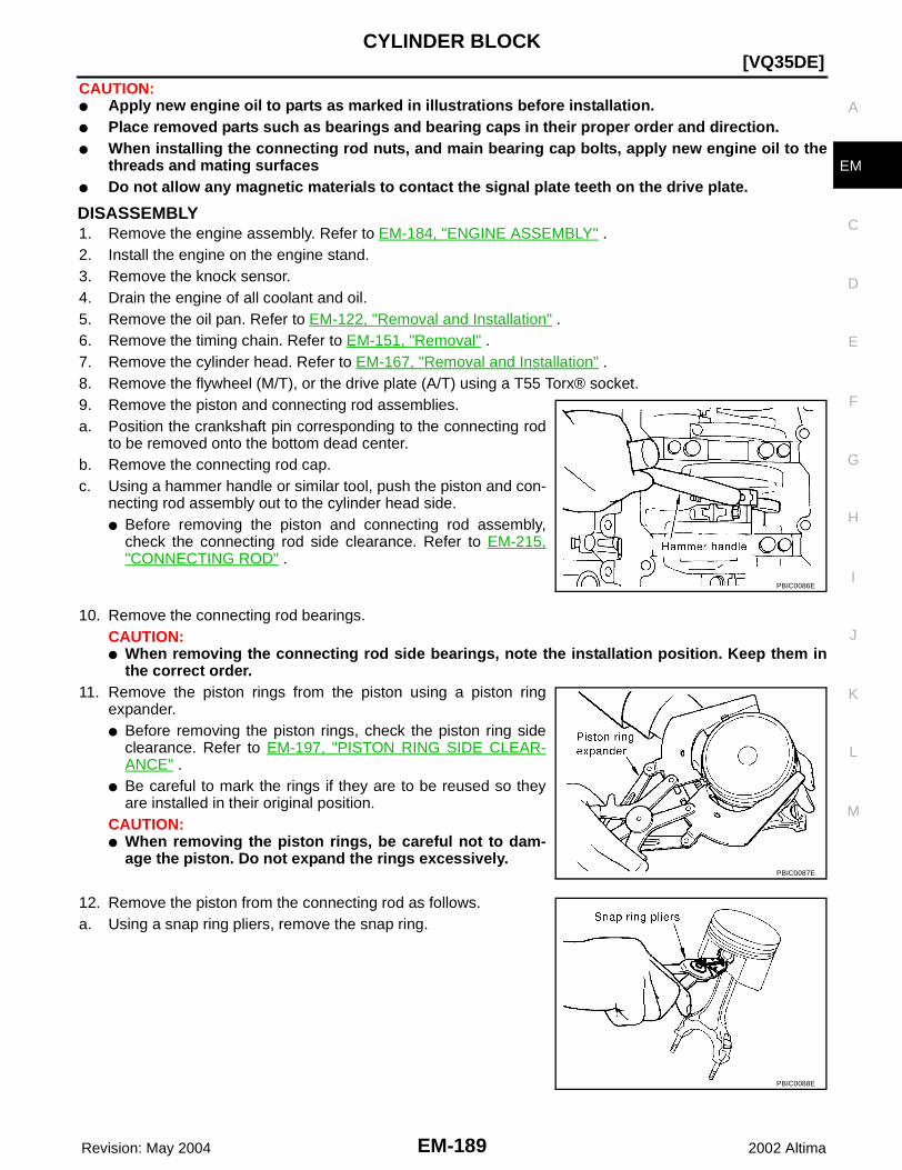
CYLINDER BLOCK
EM-189
[VQ35DE]
C
D
E
F
G
H
I
J
K
L
M
A
EM
Revision: May 2004 2002 Altima
CAUTION:● Apply new engine oil to parts as marked in illustrations before installation.● Place removed parts such as bearings and bearing caps in their proper order and direction.● When installing the connecting rod nuts, and main bearing cap bolts, apply new engine oil to the
threads and mating surfaces● Do not allow any magnetic materials to contact the signal plate teeth on the drive plate.
DISASSEMBLY1. Remove the engine assembly. Refer to EM-184, "ENGINE ASSEMBLY" .2. Install the engine on the engine stand.3. Remove the knock sensor.4. Drain the engine of all coolant and oil.5. Remove the oil pan. Refer to EM-122, "Removal and Installation" .6. Remove the timing chain. Refer to EM-151, "Removal" .7. Remove the cylinder head. Refer to EM-167, "Removal and Installation" .8. Remove the flywheel (M/T), or the drive plate (A/T) using a T55 Torx® socket.9. Remove the piston and connecting rod assemblies.a. Position the crankshaft pin corresponding to the connecting rod
to be removed onto the bottom dead center. b. Remove the connecting rod cap. c. Using a hammer handle or similar tool, push the piston and con-
necting rod assembly out to the cylinder head side. ● Before removing the piston and connecting rod assembly,
check the connecting rod side clearance. Refer to EM-215,"CONNECTING ROD" .
10. Remove the connecting rod bearings. CAUTION:● When removing the connecting rod side bearings, note the installation position. Keep them in
the correct order.11. Remove the piston rings from the piston using a piston ring
expander. ● Before removing the piston rings, check the piston ring side
clearance. Refer to EM-197, "PISTON RING SIDE CLEAR-ANCE" .
● Be careful to mark the rings if they are to be reused so theyare installed in their original position.
CAUTION:● When removing the piston rings, be careful not to dam-
age the piston. Do not expand the rings excessively.
12. Remove the piston from the connecting rod as follows. a. Using a snap ring pliers, remove the snap ring.
PBIC0086E
PBIC0087E
PBIC0088E

EM-190 Revision: May 2004
[VQ35DE]CYLINDER BLOCK
2002 Altima
b. Heat the pistons to 60° - 70°C (140° - 158°F).
c. Push out the piston pin with a suitable tool, with an outer diame-ter approximately 20 mm (0.8 in).
13. Remove the rear oil seal retainer from the cylinder block.● Insert a screwdriver or similar tool between the rear end of the crankshaft counter weight and rear oil
seal retainer, and separate the liquid gasket to remove.CAUTION:Be careful not to damage the mating surface.NOTE:When replacing the rear oil seal during on-vehicle service, it is necessary to remove the oil pan. Refer toEM-122, "Removal and Installation" .
14. Loosen the bolts in the numerical order as shown and removethe main bearing beam, bearing caps and crankshaft. ● Before loosening the main bearing cap bolts, measure the
crankshaft side clearance.Refer to EM-201, "CRANKSHAFT" .
15. Remove the oil jets.● Note the location of the knock pins for installation.
16. Remove the main bearings and thrust bearings from the cylinderblock and main bearing caps.● When removing them, note the direction and position. Keep
them in the correct order for installation.
SEM965A
EMM0072D
SEM842E
SEM454G
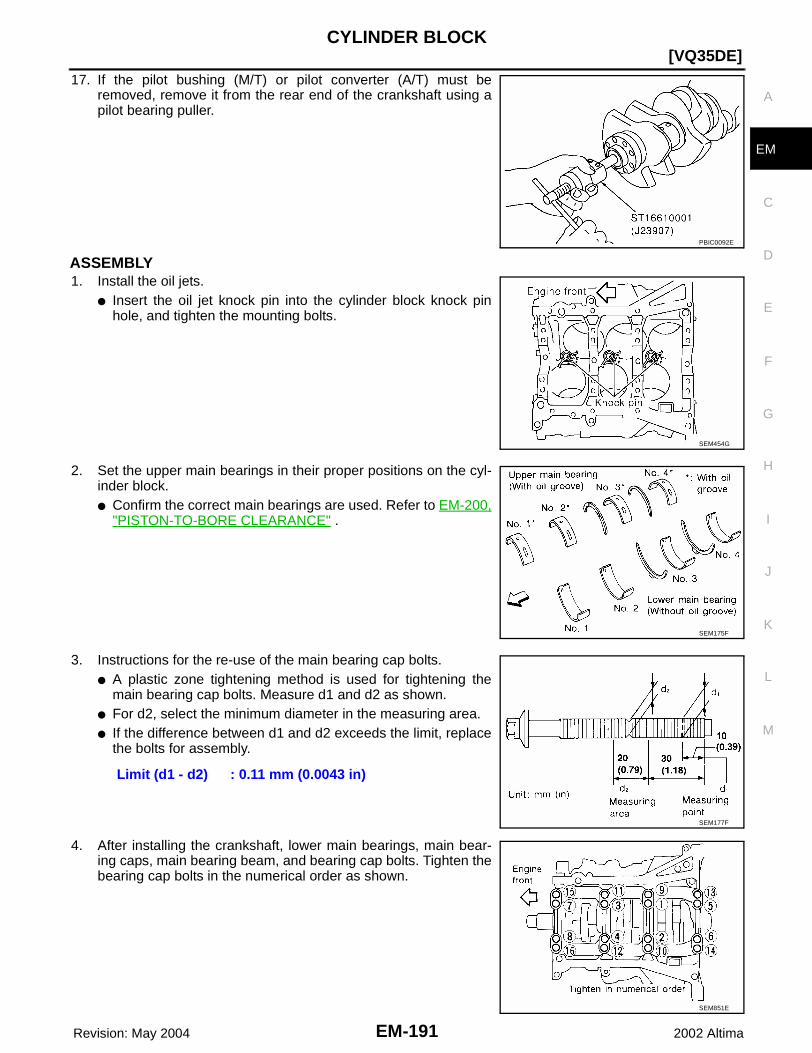
CYLINDER BLOCK
EM-191
[VQ35DE]
C
D
E
F
G
H
I
J
K
L
M
A
EM
Revision: May 2004 2002 Altima
17. If the pilot bushing (M/T) or pilot converter (A/T) must beremoved, remove it from the rear end of the crankshaft using apilot bearing puller.
ASSEMBLY1. Install the oil jets.
● Insert the oil jet knock pin into the cylinder block knock pinhole, and tighten the mounting bolts.
2. Set the upper main bearings in their proper positions on the cyl-inder block.● Confirm the correct main bearings are used. Refer to EM-200,
"PISTON-TO-BORE CLEARANCE" .
3. Instructions for the re-use of the main bearing cap bolts.● A plastic zone tightening method is used for tightening the
main bearing cap bolts. Measure d1 and d2 as shown. ● For d2, select the minimum diameter in the measuring area.● If the difference between d1 and d2 exceeds the limit, replace
the bolts for assembly.
4. After installing the crankshaft, lower main bearings, main bear-ing caps, main bearing beam, and bearing cap bolts. Tighten thebearing cap bolts in the numerical order as shown.
PBIC0092E
SEM454G
SEM175F
Limit (d1 - d2) : 0.11 mm (0.0043 in)
SEM177F
SEM851E
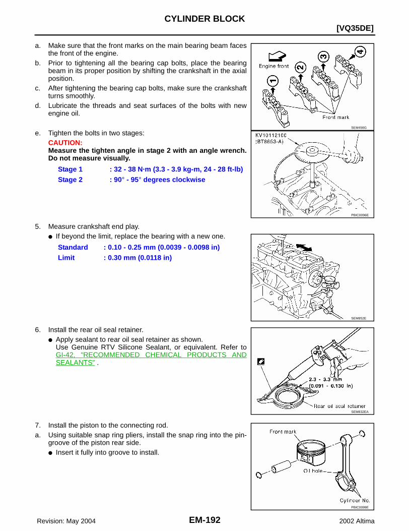
EM-192 Revision: May 2004
[VQ35DE]CYLINDER BLOCK
2002 Altima
a. Make sure that the front marks on the main bearing beam facesthe front of the engine.
b. Prior to tightening all the bearing cap bolts, place the bearingbeam in its proper position by shifting the crankshaft in the axialposition.
c. After tightening the bearing cap bolts, make sure the crankshaftturns smoothly.
d. Lubricate the threads and seat surfaces of the bolts with newengine oil.
e. Tighten the bolts in two stages:CAUTION:Measure the tighten angle in stage 2 with an angle wrench.Do not measure visually.
5. Measure crankshaft end play.● If beyond the limit, replace the bearing with a new one.
6. Install the rear oil seal retainer.● Apply sealant to rear oil seal retainer as shown.
Use Genuine RTV Silicone Sealant, or equivalent. Refer toGI-42, "RECOMMENDED CHEMICAL PRODUCTS ANDSEALANTS" .
7. Install the piston to the connecting rod. a. Using suitable snap ring pliers, install the snap ring into the pin-
groove of the piston rear side. ● Insert it fully into groove to install.
Stage 1 : 32 - 38 N·m (3.3 - 3.9 kg-m, 24 - 28 ft-lb)Stage 2 : 90° - 95° degrees clockwise
SEM456G
PBIC0096E
Standard : 0.10 - 0.25 mm (0.0039 - 0.0098 in)Limit : 0.30 mm (0.0118 in)
SEM852E
SEM832EA
PBIC0099E

CYLINDER BLOCK
EM-193
[VQ35DE]
C
D
E
F
G
H
I
J
K
L
M
A
EM
Revision: May 2004 2002 Altima
b. Install the piston to the connecting rod.● Heat the piston until the piston pin can be pushed in by hand
without excess force [approx. 60° - 70°C (140° to 158°F)].From the front to the rear, insert the piston pin into the pistonand through the connecting rod.
● Assemble so that the front mark on the piston crown and theoil holes and the cylinder No. on the connecting rod are posi-tioned as shown.
c. Install the snap ring into the front of the piston pin-groove. ● After installing, check that the connecting rod pivots smoothly
on the pin.
8. Using a piston ring expander, install the piston rings. ● Install the top ring and the second ring with the stamped sur-
face facing upward. If the ring is not stamped it can face ineither direction.
SEM965A
SEM838F
PBIC0088E
SEM757G
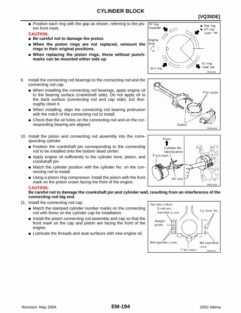
EM-194 Revision: May 2004
[VQ35DE]CYLINDER BLOCK
2002 Altima
● Position each ring with the gap as shown, referring to the pis-ton front mark.
CAUTION:● Be careful not to damage the piston.● When the piston rings are not replaced, remount the
rings in their original positions.● When replacing the piston rings, those without punch-
marks can be mounted either side up.
9. Install the connecting rod bearings to the connecting rod and theconnecting rod cap.● When installing the connecting rod bearings, apply engine oil
to the bearing surface (crankshaft side). Do not apply oil tothe back surface (connecting rod and cap side), but thor-oughly clean it.
● When installing, align the connecting rod bearing protrusionwith the notch of the connecting rod to install.
● Check that the oil holes on the connecting rod and on the cor-responding bearing are aligned.
10. Install the piston and connecting rod assembly into the corre-sponding cylinder. ● Position the crankshaft pin corresponding to the connecting
rod to be installed onto the bottom dead center. ● Apply engine oil sufficiently to the cylinder bore, piston, and
crankshaft pin. ● Match the cylinder position with the cylinder No. on the con-
necting rod to install. ● Using a piston ring compressor, install the piston with the front
mark on the piston crown facing the front of the engine. CAUTION:Be careful not to damage the crankshaft pin and cylinder wall, resulting from an interference of theconnecting rod big end.
11. Install the connecting rod cap. ● Match the stamped cylinder number marks on the connecting
rod with those on the cylinder cap for installation. ● Install the piston connecting rod assembly and cap so that the
front mark on the cap and piston are facing the front of theengine.
● Lubricate the threads and seat surfaces with new engine oil.
SEM160B
PBIC0101E
PBIC0102E
SEM457G
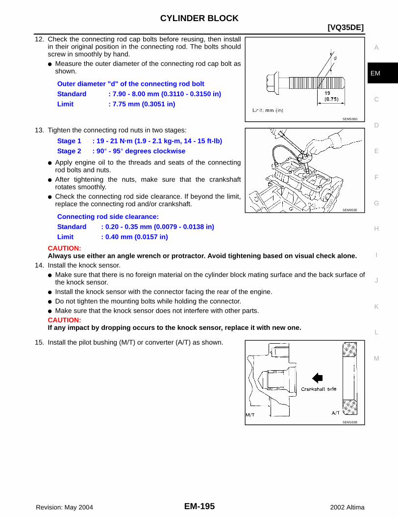
CYLINDER BLOCK
EM-195
[VQ35DE]
C
D
E
F
G
H
I
J
K
L
M
A
EM
Revision: May 2004 2002 Altima
12. Check the connecting rod cap bolts before reusing, then installin their original position in the connecting rod. The bolts shouldscrew in smoothly by hand.● Measure the outer diameter of the connecting rod cap bolt as
shown.
13. Tighten the connecting rod nuts in two stages:
● Apply engine oil to the threads and seats of the connectingrod bolts and nuts.
● After tightening the nuts, make sure that the crankshaftrotates smoothly.
● Check the connecting rod side clearance. If beyond the limit,replace the connecting rod and/or crankshaft.
CAUTION:Always use either an angle wrench or protractor. Avoid tightening based on visual check alone.
14. Install the knock sensor.● Make sure that there is no foreign material on the cylinder block mating surface and the back surface of
the knock sensor. ● Install the knock sensor with the connector facing the rear of the engine. ● Do not tighten the mounting bolts while holding the connector. ● Make sure that the knock sensor does not interfere with other parts.CAUTION:If any impact by dropping occurs to the knock sensor, replace it with new one.
15. Install the pilot bushing (M/T) or converter (A/T) as shown.
Outer diameter "d" of the connecting rod boltStandard : 7.90 - 8.00 mm (0.3110 - 0.3150 in)Limit : 7.75 mm (0.3051 in)
SEM538G
Stage 1 : 19 - 21 N·m (1.9 - 2.1 kg-m, 14 - 15 ft-lb)Stage 2 : 90° - 95° degrees clockwise
Connecting rod side clearance:Standard : 0.20 - 0.35 mm (0.0079 - 0.0138 in)Limit : 0.40 mm (0.0157 in)
SEM953E
SEM163B

EM-196 Revision: May 2004
[VQ35DE]CYLINDER BLOCK
2002 Altima
16. Install the flywheel (M/T), or the drive plate (A/T).
17. Install the cylinder head. Refer to EM-167, "Removal and Installation" .18. Install the timing chain. Refer to EM-157, "Installation" .19. Install the oil pan. Refer to EM-122, "Removal and Installation" .20. Remove the engine from the stand and install the engine assembly into the vehicle. Refer to EM-184,
"Removal and Installation" .21. Assembly of the remaining parts is in the reverse order of disassembly.22. Fill the engine with the specified oil and coolant. Refer to MA-12, "Fluids and Lubricants" .
CAUTION:Wait at least 30 minutes for the sealant to set-up before filling the engine with fluids and running it.
Inspection EBS007QH
PISTON AND PISTON PIN CLEARANCEInner Diameter of Piston Pin● Measure the inner diameter of piston pin bore "dp".
Outer Diameter of Piston Pin● Measure outer diameter of piston pin "Dp".
SEM539G
Standard diameter "dp"Grade No. 0 : 21.993 - 22.999 mm (0.8659 - 0.8661 in)Grade No. 1 : 21.999 - 22.005 mm (0.8661 - 0.8663 in)
AEM023
Standard diameter "Dp"Grade No. 0 : 21.989 - 21.995 mm (0.8657 - 0.8659 in)Grade No. 1 : 21.995 - 22.001 mm (0.8659 - 0.8662 in)
AEM024

CYLINDER BLOCK
EM-197
[VQ35DE]
C
D
E
F
G
H
I
J
K
L
M
A
EM
Revision: May 2004 2002 Altima
Piston and Piston Pin Interference FitStandard Interference Fit = "Dp" – "dp"
● If clearance is exceeds specification, replace either or both ofpiston/piston pin assembly and connecting rod assembly withreference to specification of each part.
PISTON RING SIDE CLEARANCE● Measure side clearance of piston ring and piston ring groove
with feeler gauge.
● If out of specification, replace piston ring assembly. If clearance exceeds maximum limit with new rings,replace piston
PISTON RING END GAP● Insert piston ring until it is in the middle of the cylinder bore and
measure the end gap.
● If out of specification, replace piston ring. If gap still exceeds the limit even with a new ring, re-bore cylin-der and use oversized piston and piston ring.
CONNECTING ROD BEND AND TORSION● Measure the bend and torsion of each connecting rod as shown.
Standard : [0.002 mm (0.0001 in)] - [0.006 mm (0.0002 in)] = [- 0.0004 mm (-0.0001 in)]
SEM838F
Standard Side ClearanceTop ring : 0.045 - 0.080 mm (0.0018 - 0.0031 in)2nd ring : 0.030 - 0.070 mm (0.0012 - 0.0028 in)Oil ring : 0.065 - 0.135 mm (0.0026 - 0.0053 in)
Maximum LimitTop ring : 0.11 mm (0.0043 in)2nd ring : 0.1 mm (0.004 in)Oil ring : —
SEM024AA
StandardTop ring : 0.23 - 0.33 mm (0.0091 - 0.0130 in)2nd ring : 0.33 - 0.48 mm (0.0130 - 0.0189 in)Oil ring : 0.20 - 0.50 mm (0.0079 - 0.0197 in)
Limit:Top ring : 0.54 mm (0.0213 in)2nd ring : 0.80 mm (0.0315 in)Oil ring : 0.95 mm (0.0374 in)
SEM599A
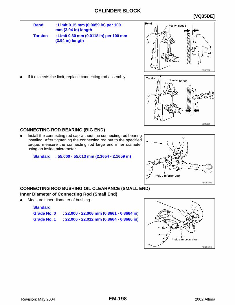
EM-198 Revision: May 2004
[VQ35DE]CYLINDER BLOCK
2002 Altima
● If it exceeds the limit, replace connecting rod assembly.
CONNECTING ROD BEARING (BIG END)● Install the connecting rod cap without the connecting rod bearing
installed. After tightening the connecting rod nut to the specifiedtorque, measure the connecting rod large end inner diameterusing an inside micrometer.
CONNECTING ROD BUSHING OIL CLEARANCE (SMALL END)Inner Diameter of Connecting Rod (Small End)● Measure inner diameter of bushing.
Bend : Limit 0.15 mm (0.0059 in) per 100 mm (3.94 in) length
Torsion : Limit 0.30 mm (0.0118 in) per 100 mm (3.94 in) length
SEM038F
SEM003F
Standard : 55.000 - 55.013 mm (2.1654 - 2.1659 in)
PBIC0119E
StandardGrade No. 0 : 22.000 - 22.006 mm (0.8661 - 0.8664 in)Grade No. 1 : 22.006 - 22.012 mm (0.8664 - 0.8666 in)
PBIC0120E
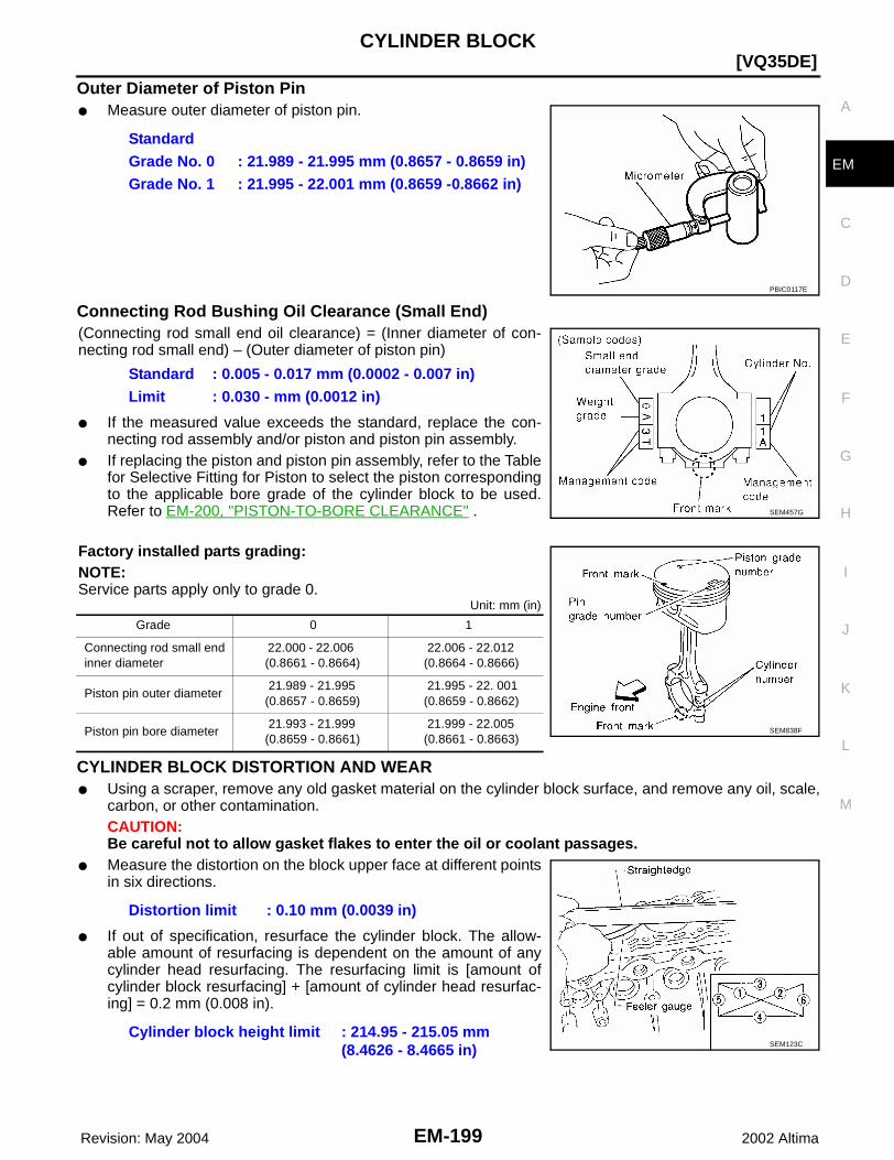
CYLINDER BLOCK
EM-199
[VQ35DE]
C
D
E
F
G
H
I
J
K
L
M
A
EM
Revision: May 2004 2002 Altima
Outer Diameter of Piston Pin● Measure outer diameter of piston pin.
Connecting Rod Bushing Oil Clearance (Small End)(Connecting rod small end oil clearance) = (Inner diameter of con-necting rod small end) – (Outer diameter of piston pin)
● If the measured value exceeds the standard, replace the con-necting rod assembly and/or piston and piston pin assembly.
● If replacing the piston and piston pin assembly, refer to the Tablefor Selective Fitting for Piston to select the piston correspondingto the applicable bore grade of the cylinder block to be used.Refer to EM-200, "PISTON-TO-BORE CLEARANCE" .
Factory installed parts grading:NOTE:Service parts apply only to grade 0.
Unit: mm (in)
CYLINDER BLOCK DISTORTION AND WEAR● Using a scraper, remove any old gasket material on the cylinder block surface, and remove any oil, scale,
carbon, or other contamination. CAUTION:Be careful not to allow gasket flakes to enter the oil or coolant passages.
● Measure the distortion on the block upper face at different pointsin six directions.
● If out of specification, resurface the cylinder block. The allow-able amount of resurfacing is dependent on the amount of anycylinder head resurfacing. The resurfacing limit is [amount ofcylinder block resurfacing] + [amount of cylinder head resurfac-ing] = 0.2 mm (0.008 in).
StandardGrade No. 0 : 21.989 - 21.995 mm (0.8657 - 0.8659 in)Grade No. 1 : 21.995 - 22.001 mm (0.8659 -0.8662 in)
PBIC0117E
Standard : 0.005 - 0.017 mm (0.0002 - 0.007 in)Limit : 0.030 - mm (0.0012 in)
SEM457G
Grade 0 1
Connecting rod small end inner diameter
22.000 - 22.006 (0.8661 - 0.8664)
22.006 - 22.012 (0.8664 - 0.8666)
Piston pin outer diameter 21.989 - 21.995 (0.8657 - 0.8659)
21.995 - 22. 001 (0.8659 - 0.8662)
Piston pin bore diameter 21.993 - 21.999 (0.8659 - 0.8661)
21.999 - 22.005 (0.8661 - 0.8663)
SEM838F
Distortion limit : 0.10 mm (0.0039 in)
Cylinder block height limit : 214.95 - 215.05 mm (8.4626 - 8.4665 in) SEM123C

EM-200 Revision: May 2004
[VQ35DE]CYLINDER BLOCK
2002 Altima
INNER DIAMETER OF MAIN BEARING HOUSING● Install the main bearing caps with the main bearings removed,
and tighten the mounting bolts to the specified torque.● Using a bore gauge, measure the inner diameter of the main
bearing housing.
● If out of the standard, replace the cylinder block and main bear-ing caps as an assembly. NOTE:These components cannot be replaced as a single unit, becausethey were processed together.
PISTON-TO-BORE CLEARANCE1. Using a bore gauge, measure cylinder bore for wear, out-of-round and taper. The X axis is in the longitudi-
nal direction of the engine.
Cylinder bore inner diameter
If it exceeds the limit, rebore all cylinders. Replace cylinder blockif necessary.
2. Check for scratches and seizure. If seizure is found, hone it.● If both cylinder block and piston are replaced with new ones,
select piston of the same grade number punched on cylinderblock rear position. These numbers are punched in either Ara-bic or Roman numerals.
Standard : 63.993 - 64.017 mm (2.5194 - 2.5203 in)
SEM845E
Grade No. Standard inner diameter Wear limit
No. 1 95.500 - 95.510 mm (3.7598 - 3.7602 in)
0.20 mm (0.0079 in)No. 2 95.510 - 95.520 mm (3.7602 - 3.7606 in)
No. 3 95.520 - 95.530 mm (3.7606 - 3.7610 in)
SEM843E
Out-of-round (Y − X) : limit 0.015 mm (0.0006 in)Taper (C − A) : limit 0.015 mm (0.0006 in)
SEM321AA
SEM756G
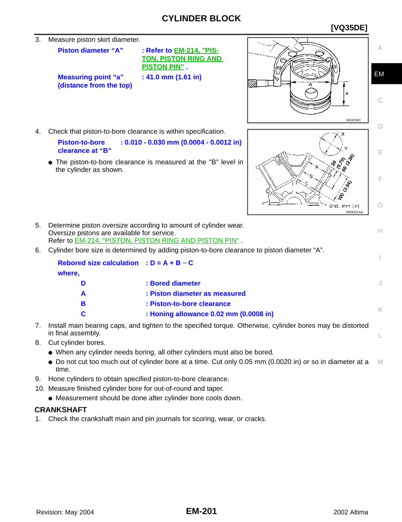
CYLINDER BLOCK
EM-201
[VQ35DE]
C
D
E
F
G
H
I
J
K
L
M
A
EM
Revision: May 2004 2002 Altima
3. Measure piston skirt diameter.
4. Check that piston-to-bore clearance is within specification.
● The piston-to-bore clearance is measured at the "B" level inthe cylinder as shown.
5. Determine piston oversize according to amount of cylinder wear.Oversize pistons are available for service.Refer to EM-214, "PISTON, PISTON RING AND PISTON PIN" .
6. Cylinder bore size is determined by adding piston-to-bore clearance to piston diameter “A”.
7. Install main bearing caps, and tighten to the specified torque. Otherwise, cylinder bores may be distortedin final assembly.
8. Cut cylinder bores.● When any cylinder needs boring, all other cylinders must also be bored.● Do not cut too much out of cylinder bore at a time. Cut only 0.05 mm (0.0020 in) or so in diameter at a
time.9. Hone cylinders to obtain specified piston-to-bore clearance.10. Measure finished cylinder bore for out-of-round and taper.
● Measurement should be done after cylinder bore cools down.
CRANKSHAFT1. Check the crankshaft main and pin journals for scoring, wear, or cracks.
Piston diameter “A” : Refer to EM-214, "PIS-TON, PISTON RING AND PISTON PIN" .
Measuring point “a” (distance from the top)
: 41.0 mm (1.61 in)
SEM258C
Piston-to-bore clearance at “B”
: 0.010 - 0.030 mm (0.0004 - 0.0012 in)
SEM321AA
Rebored size calculation : D = A + B − Cwhere, D : Bored diameter A : Piston diameter as measured B : Piston-to-bore clearance C : Honing allowance 0.02 mm (0.0008 in)
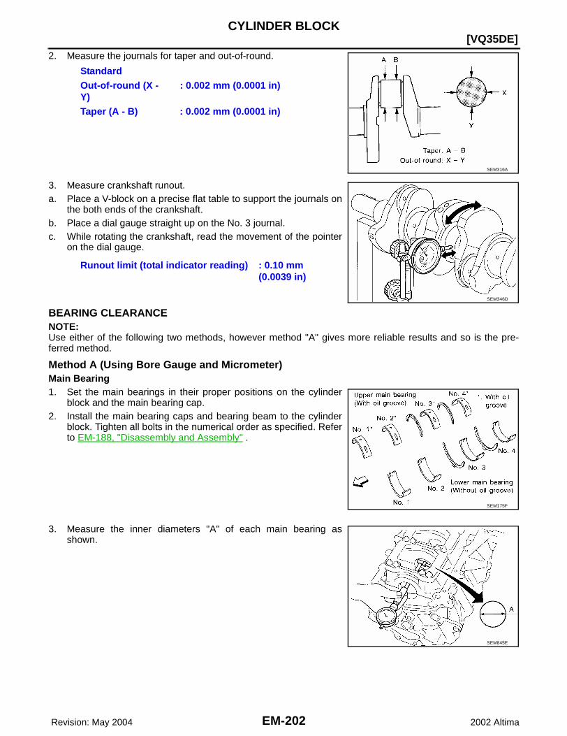
EM-202 Revision: May 2004
[VQ35DE]CYLINDER BLOCK
2002 Altima
2. Measure the journals for taper and out-of-round.
3. Measure crankshaft runout.a. Place a V-block on a precise flat table to support the journals on
the both ends of the crankshaft.b. Place a dial gauge straight up on the No. 3 journal. c. While rotating the crankshaft, read the movement of the pointer
on the dial gauge.
BEARING CLEARANCENOTE:Use either of the following two methods, however method "A" gives more reliable results and so is the pre-ferred method.
Method A (Using Bore Gauge and Micrometer)Main Bearing1. Set the main bearings in their proper positions on the cylinder
block and the main bearing cap.2. Install the main bearing caps and bearing beam to the cylinder
block. Tighten all bolts in the numerical order as specified. Referto EM-188, "Disassembly and Assembly" .
3. Measure the inner diameters "A" of each main bearing asshown.
StandardOut-of-round (X - Y)
: 0.002 mm (0.0001 in)
Taper (A - B) : 0.002 mm (0.0001 in)
SEM316A
Runout limit (total indicator reading) : 0.10 mm (0.0039 in)
SEM346D
SEM175F
SEM845E

CYLINDER BLOCK
EM-203
[VQ35DE]
C
D
E
F
G
H
I
J
K
L
M
A
EM
Revision: May 2004 2002 Altima
4. Measure the outer diameters "Dm" of each crankshaft main jour-nal as shown.
5. Calculate the main bearing clearance.Main bearing clearance = "A" - "Dm"
● If it exceeds the limit, replace the bearing.● If clearance cannot be adjusted using any standard bearing
grade, grind crankshaft journal and use an undersized bear-ing.
● When grinding the crankshaft journal, confirm that the "L"dimension in the fillet role is more than the specified limit.
6. If the crankshaft or the cylinder block is replaced with a new one, select thickness of the main bearings asfollows:
a. The grade number of each cylinder block main journal ispunched on the respective cylinder block. These numbers arepunched in either Arabic or Roman numerals. If measured diam-eter is out of the grade punched, decide suitable grade fromavailable main bearings.
b. The grade number of each crankshaft main journal is punchedon the crankshaft end. These numbers are punched in eitherArabic or Roman numerals. If measured diameter is out of gradepunched, decide the suitable grade from available main bear-ings.
Standard : 0.035 - 0.045 mm (0.0014 - 0.0018 in)Limit : 0.065 mm (0.0026 in)
AEM033
"L" : 0.1 mm (0.004 in)
SEM964
SEM756G
SEM452G

EM-204 Revision: May 2004
[VQ35DE]CYLINDER BLOCK
2002 Altima
c. Select the main bearing suitable thickness according to the following table:
Connecting Rod Bearing (Big End)1. Install the connecting rod bearing to the connecting rod and cap.2. Install the connecting rod cap to the connecting rod. Tighten to specification. Refer to EM-188, "Disassem-
bly and Assembly" .3. Measure the inner diameter "C" of each connecting rod (big end)
as shown.
WBIA0092E
AEM027
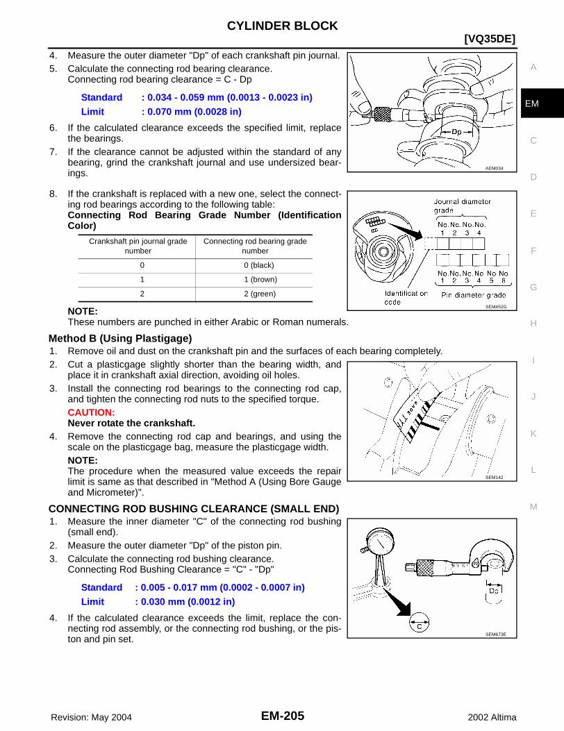
CYLINDER BLOCK
EM-205
[VQ35DE]
C
D
E
F
G
H
I
J
K
L
M
A
EM
Revision: May 2004 2002 Altima
4. Measure the outer diameter "Dp" of each crankshaft pin journal.5. Calculate the connecting rod bearing clearance.
Connecting rod bearing clearance = C - Dp
6. If the calculated clearance exceeds the specified limit, replacethe bearings.
7. If the clearance cannot be adjusted within the standard of anybearing, grind the crankshaft journal and use undersized bear-ings.
8. If the crankshaft is replaced with a new one, select the connect-ing rod bearings according to the following table:Connecting Rod Bearing Grade Number (IdentificationColor)
NOTE:These numbers are punched in either Arabic or Roman numerals.
Method B (Using Plastigage)1. Remove oil and dust on the crankshaft pin and the surfaces of each bearing completely. 2. Cut a plasticgage slightly shorter than the bearing width, and
place it in crankshaft axial direction, avoiding oil holes.3. Install the connecting rod bearings to the connecting rod cap,
and tighten the connecting rod nuts to the specified torque. CAUTION:Never rotate the crankshaft.
4. Remove the connecting rod cap and bearings, and using thescale on the plasticgage bag, measure the plasticgage width. NOTE:The procedure when the measured value exceeds the repairlimit is same as that described in "Method A (Using Bore Gaugeand Micrometer)".
CONNECTING ROD BUSHING CLEARANCE (SMALL END)1. Measure the inner diameter "C" of the connecting rod bushing
(small end).2. Measure the outer diameter "Dp" of the piston pin.3. Calculate the connecting rod bushing clearance.
Connecting Rod Bushing Clearance = "C" - "Dp"
4. If the calculated clearance exceeds the limit, replace the con-necting rod assembly, or the connecting rod bushing, or the pis-ton and pin set.
Standard : 0.034 - 0.059 mm (0.0013 - 0.0023 in)Limit : 0.070 mm (0.0028 in)
AEM034
Crankshaft pin journal grade number
Connecting rod bearing grade number
0 0 (black)
1 1 (brown)
2 2 (green)
SEM452G
SEM142
Standard : 0.005 - 0.017 mm (0.0002 - 0.0007 in)Limit : 0.030 mm (0.0012 in)
SEM673E
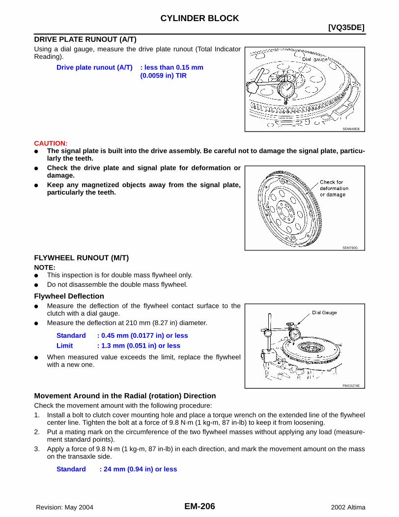
EM-206 Revision: May 2004
[VQ35DE]CYLINDER BLOCK
2002 Altima
DRIVE PLATE RUNOUT (A/T)Using a dial gauge, measure the drive plate runout (Total IndicatorReading).
CAUTION:● The signal plate is built into the drive assembly. Be careful not to damage the signal plate, particu-
larly the teeth.● Check the drive plate and signal plate for deformation or
damage.● Keep any magnetized objects away from the signal plate,
particularly the teeth.
FLYWHEEL RUNOUT (M/T)NOTE:● This inspection is for double mass flywheel only.● Do not disassemble the double mass flywheel.
Flywheel Deflection● Measure the deflection of the flywheel contact surface to the
clutch with a dial gauge.● Measure the deflection at 210 mm (8.27 in) diameter.
● When measured value exceeds the limit, replace the flywheelwith a new one.
Movement Around in the Radial (rotation) DirectionCheck the movement amount with the following procedure:1. Install a bolt to clutch cover mounting hole and place a torque wrench on the extended line of the flywheel
center line. Tighten the bolt at a force of 9.8 N·m (1 kg-m, 87 in-lb) to keep it from loosening.2. Put a mating mark on the circumference of the two flywheel masses without applying any load (measure-
ment standard points).3. Apply a force of 9.8 N·m (1 kg-m, 87 in-lb) in each direction, and mark the movement amount on the mass
on the transaxle side.
Drive plate runout (A/T) : less than 0.15 mm (0.0059 in) TIR
SEM849EB
SEM760G
Standard : 0.45 mm (0.0177 in) or lessLimit : 1.3 mm (0.051 in) or less
PBIC0274E
Standard : 24 mm (0.94 in) or less

CYLINDER BLOCK
EM-207
[VQ35DE]
C
D
E
F
G
H
I
J
K
L
M
A
EM
Revision: May 2004 2002 Altima
4. Measure dimensions of movement amounts A and B on the cir-cumference of the flywheel on the transaxle side.
5. When the measured value exceeds the standard, replace theflywheel.
KBIA0297E
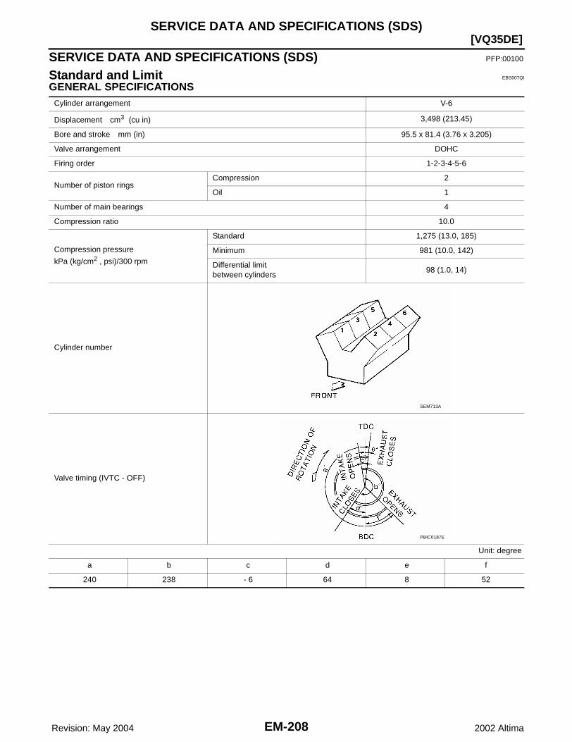
EM-208 Revision: May 2004
[VQ35DE]SERVICE DATA AND SPECIFICATIONS (SDS)
2002 Altima
SERVICE DATA AND SPECIFICATIONS (SDS) PFP:00100
Standard and Limit EBS007QI
GENERAL SPECIFICATIONSCylinder arrangement V-6
Displacement cm3 (cu in) 3,498 (213.45)
Bore and stroke mm (in) 95.5 x 81.4 (3.76 x 3.205)
Valve arrangement DOHC
Firing order 1-2-3-4-5-6
Number of piston ringsCompression 2
Oil 1
Number of main bearings 4
Compression ratio 10.0
Compression pressure
kPa (kg/cm2 , psi)/300 rpm
Standard 1,275 (13.0, 185)
Minimum 981 (10.0, 142)
Differential limit between cylinders
98 (1.0, 14)
Cylinder number
Valve timing (IVTC - OFF)
Unit: degree
a b c d e f
240 238 - 6 64 8 52
SEM713A
PBIC0187E

SERVICE DATA AND SPECIFICATIONS (SDS)
EM-209
[VQ35DE]
C
D
E
F
G
H
I
J
K
L
M
A
EM
Revision: May 2004 2002 Altima
CYLINDER HEADUnit: mm (in)
VALVEValve Dimensions
Unit: mm (in)
Valve ClearanceUnit: mm (in)
*: Approximately 80°C (176°F)
Valve Spring
Standard Limit
Head surface distortion Less than 0.03 (0.0012) 0.1 (0.004)
SEM949E
Valve head diameter “D”Intake 37.0 - 37.3 (1.4567 - 1.4685)
Exhaust 31.2 - 31.5 (1.228 - 1.240)
Valve length “L”Intake 96.12 - 96.62 (3.7842 - 3.8039)
Exhaust 93.65 - 94.15 (3.6870 - 3.7067)
Valve stem diameter “d”Intake 5.965 - 5.980 (0.2348 - 0.2354)
Exhaust 5.945 - 5.960 (0.2341 - 0.2346)
Valve seat angle “α”Intake
45°15′ - 45°45′Exhaust
Valve margin “T”Intake 1.15 - 1.45 (0.0453 - 0.0571)
Exhaust 1.45 - 1.75 (0.0571 - 0.0689)
Valve margin “T” limit More than 0.5 (0.020)
Valve stem end surface grinding limit Less than 0.2 (0.008)
SEM188
Cold Hot* (reference data)
Intake 0.26 - 0.34 (0.010 - 0.013) 0.304 - 0.416 (0.012 - 0.016)
Exhaust 0.29 - 0.37 (0.011 - 0.015) 0.308 - 0.432 (0.012 - 0.017)
Free height mm (in) 47.10 (1.8543)

EM-210 Revision: May 2004
[VQ35DE]SERVICE DATA AND SPECIFICATIONS (SDS)
2002 Altima
Valve LifterUnit: mm (in)
Pressure N (kg, lb) at height mm (in)Standard 202 (20.6, 45.4) at 37.0 (1.457)
Limit 436 (44.5, 98.1) at 28.2 (1.110)
Out-of-square mm (in) Less than 2.0 (0.079)
Valve lifter outer diameter 34.960 - 34.975 (1.3764 - 1.3770)
Lifter guide inner diameter 35.000 - 35.021 (1.3780 - 1.3788)
Clearance between lifter and lifter guide 0.025 - 0.061 (0.0010 - 0.0024)
Identification Mark Thickness mm (in)
788C 7.88 (0.3102)
790C 7.90 (0.3110)
792C 7.92 (0.3118)
794C 7.94 (0.3126)
796C 7.96 (0.3134)
798C 7.98 (0.3142)
800C 8.00 (0.3150)
802C 8.02 (03.157)
804C 8.04 (0.3165)
806C 8.06 (0.3173)
808C 8.08 (0.3181)
810C 8.10 (0.3189)
812C 8.12 (0.3197)
814C 8.14 (0.3205)
816C 8.16 (0.3213)
818C 8.18 (0.3220)
820C 8.20 (0.3228)
822C 8.22 (0.3236)
824C 8.24 (0.3244)
826C 8.26 (0.3252)
828C 8.28 (0.3260)
830C 8.30 (0.3268)
832C 8.32 (0.3276)
834C 8.34 (0.3283)
836C 8.36 (0.3291)
SEM758G
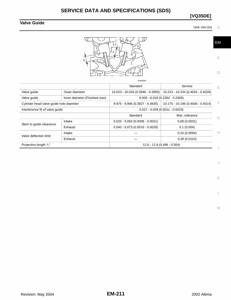
SERVICE DATA AND SPECIFICATIONS (SDS)
EM-211
[VQ35DE]
C
D
E
F
G
H
I
J
K
L
M
A
EM
Revision: May 2004 2002 Altima
Valve GuideUnit: mm (in)
Standard Service
Valve guide Outer diameter 10.023 - 10.034 (0.3946 - 0.3950) 10.223 - 10.234 (0.4025 - 0.4029)
Valve guide Inner diameter (Finished size) 6.000 - 6.018 (0.2362 - 0.2369)
Cylinder head valve guide hole diameter 9.975 - 9.996 (0.3927 - 0.3935) 10.175 - 10.196 (0.4006 - 0.4014)
Interference fit of valve guide 0.027 - 0.059 (0.0011 - 0.0023)
Standard Max. tolerance
Stem to guide clearanceIntake 0.020 - 0.053 (0.0008 - 0.0021) 0.08 (0.0031)
Exhaust 0.040 - 0.073 (0.0016 - 0.0029) 0.1 (0.004)
Valve deflection limitIntake — 0.24 (0.0094)
Exhaust — 0.28 (0.0110)
Projection length “L” 12.6 - 12.8 (0.496 - 0.504)
SEM950E

EM-212 Revision: May 2004
[VQ35DE]SERVICE DATA AND SPECIFICATIONS (SDS)
2002 Altima
Valve SeatUnit: mm (in)
Standard Service
Cylinder head seat recess diameter (D)
Intake 38.000 - 38.016 (1.4961 - 1.4967) 38.500 - 38.516 (1.5157 - 1.5164)
Exhaust 32.200 - 32.216 (1.2677 - 1.2683) 32.700 - 32.716 (1.2874 - 1.2880)
Valve seat interference fitIntake 0.081 - 0.113 (0.0032 - 0.0044)
Exhaust 0.064 - 0.096 (0.0025 - 0.0038)
Valve seat outer diameter (d)Intake 38.097 - 38.113 (1.4999 - 1.5005) 38.597 - 38.613 (1.5196 - 1.5202)
Exhaust 32.280 - 32.296 (1.2709 - 1.2715) 32.780 - 32.796 (1.2905 - 1.2912)
Height (h)Intake 5.9 - 6.0 (0.232 - 0.236) 5.05 - 5.15 (0.1988 - 0.2028)
Exhaust 5.9 - 6.0 (0.232 - 0.236) 4.95 - 5.05 (0.1949 - 0.1988)
Depth (H) 5.9 - 6.1 (0.232 - 0.240)
Depth (L)Intake 41.07 - 41.67 (1.6169 - 1.6405)
Exhaust 41.00 - 41.60 (1.6142 - 1.6378)
SEM021EB
SEM621F
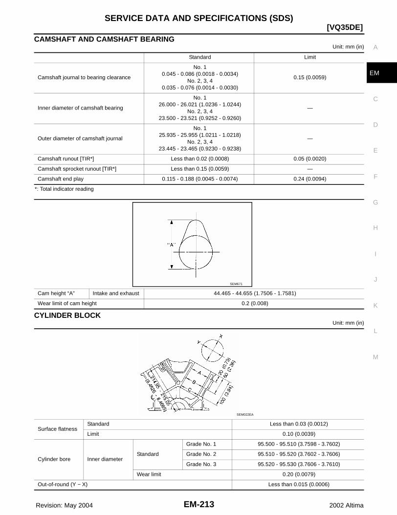
SERVICE DATA AND SPECIFICATIONS (SDS)
EM-213
[VQ35DE]
C
D
E
F
G
H
I
J
K
L
M
A
EM
Revision: May 2004 2002 Altima
CAMSHAFT AND CAMSHAFT BEARINGUnit: mm (in)
*: Total indicator reading
CYLINDER BLOCKUnit: mm (in)
Standard Limit
Camshaft journal to bearing clearance
No. 10.045 - 0.086 (0.0018 - 0.0034)
No. 2, 3, 40.035 - 0.076 (0.0014 - 0.0030)
0.15 (0.0059)
Inner diameter of camshaft bearing
No. 126.000 - 26.021 (1.0236 - 1.0244)
No. 2, 3, 423.500 - 23.521 (0.9252 - 0.9260)
—
Outer diameter of camshaft journal
No. 125.935 - 25.955 (1.0211 - 1.0218)
No. 2, 3, 423.445 - 23.465 (0.9230 - 0.9238)
—
Camshaft runout [TIR*] Less than 0.02 (0.0008) 0.05 (0.0020)
Camshaft sprocket runout [TIR*] Less than 0.15 (0.0059) —
Camshaft end play 0.115 - 0.188 (0.0045 - 0.0074) 0.24 (0.0094)
Cam height “A” Intake and exhaust 44.465 - 44.655 (1.7506 - 1.7581)
Wear limit of cam height 0.2 (0.008)
SEM671
Surface flatnessStandard Less than 0.03 (0.0012)
Limit 0.10 (0.0039)
Cylinder bore Inner diameterStandard
Grade No. 1 95.500 - 95.510 (3.7598 - 3.7602)
Grade No. 2 95.510 - 95.520 (3.7602 - 3.7606)
Grade No. 3 95.520 - 95.530 (3.7606 - 3.7610)
Wear limit 0.20 (0.0079)
Out-of-round (Y − X) Less than 0.015 (0.0006)
SEM022EA
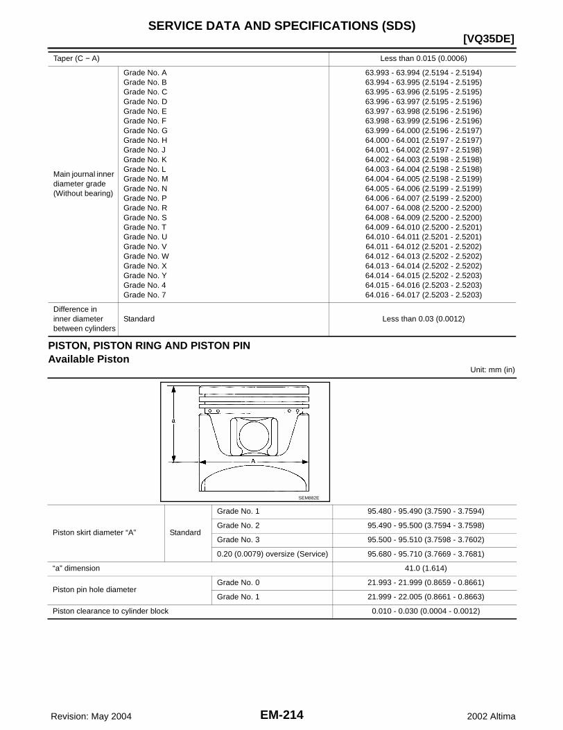
EM-214 Revision: May 2004
[VQ35DE]SERVICE DATA AND SPECIFICATIONS (SDS)
2002 Altima
PISTON, PISTON RING AND PISTON PINAvailable Piston
Unit: mm (in)
Taper (C − A) Less than 0.015 (0.0006)
Main journal inner diameter grade(Without bearing)
Grade No. AGrade No. BGrade No. CGrade No. DGrade No. EGrade No. FGrade No. GGrade No. HGrade No. JGrade No. KGrade No. LGrade No. MGrade No. NGrade No. PGrade No. RGrade No. SGrade No. TGrade No. UGrade No. VGrade No. WGrade No. XGrade No. YGrade No. 4Grade No. 7
63.993 - 63.994 (2.5194 - 2.5194)63.994 - 63.995 (2.5194 - 2.5195)63.995 - 63.996 (2.5195 - 2.5195)63.996 - 63.997 (2.5195 - 2.5196)63.997 - 63.998 (2.5196 - 2.5196)63.998 - 63.999 (2.5196 - 2.5196)63.999 - 64.000 (2.5196 - 2.5197)64.000 - 64.001 (2.5197 - 2.5197)64.001 - 64.002 (2.5197 - 2.5198)64.002 - 64.003 (2.5198 - 2.5198)64.003 - 64.004 (2.5198 - 2.5198)64.004 - 64.005 (2.5198 - 2.5199)64.005 - 64.006 (2.5199 - 2.5199)64.006 - 64.007 (2.5199 - 2.5200)64.007 - 64.008 (2.5200 - 2.5200)64.008 - 64.009 (2.5200 - 2.5200)64.009 - 64.010 (2.5200 - 2.5201)64.010 - 64.011 (2.5201 - 2.5201)64.011 - 64.012 (2.5201 - 2.5202)64.012 - 64.013 (2.5202 - 2.5202)64.013 - 64.014 (2.5202 - 2.5202)64.014 - 64.015 (2.5202 - 2.5203)64.015 - 64.016 (2.5203 - 2.5203)64.016 - 64.017 (2.5203 - 2.5203)
Difference in inner diameter between cylinders
Standard Less than 0.03 (0.0012)
Piston skirt diameter “A” Standard
Grade No. 1 95.480 - 95.490 (3.7590 - 3.7594)
Grade No. 2 95.490 - 95.500 (3.7594 - 3.7598)
Grade No. 3 95.500 - 95.510 (3.7598 - 3.7602)
0.20 (0.0079) oversize (Service) 95.680 - 95.710 (3.7669 - 3.7681)
“a” dimension 41.0 (1.614)
Piston pin hole diameterGrade No. 0 21.993 - 21.999 (0.8659 - 0.8661)
Grade No. 1 21.999 - 22.005 (0.8661 - 0.8663)
Piston clearance to cylinder block 0.010 - 0.030 (0.0004 - 0.0012)
SEM882E

SERVICE DATA AND SPECIFICATIONS (SDS)
EM-215
[VQ35DE]
C
D
E
F
G
H
I
J
K
L
M
A
EM
Revision: May 2004 2002 Altima
Piston RingUnit: mm (in)
Piston PinUnit: mm (in)
*: Values measured at ambient temperature of 20°C (68°F)
CONNECTING RODUnit: mm (in)
*: After installing in connecting rod
Standard Limit
Side clearance
Top 0.045 - 0.080 (0.0018 - 0.0031) 0.11 (0.0043)
2nd 0.030 - 0.070 (0.0012 - 0.0028) 0.1 (0.004)
Oil ring 0.065 - 0.135 (0.0026 - 0.0053) —
End gap
Top 0.23 - 0.33 (0.0091 - 0.0130) 0.54 (0.0213)
2nd 0.33 - 0.48 (0.0130 - 0.0189) 0.80 (0.0315)
Oil (rail ring) 0.20 - 0.50 (0.0079 - 0.0197) 0.95 (0.0374)
Piston pin outer diameterGrade No. 0 21.989 - 21.995 (0.8657 - 0.8659)
Grade No. 1 21.995 - 22.001 (0.8659 - 0.8662)
Interference fit of piston pin to piston 0.002 - 0.006 (0.0001 - 0.0002)
Piston pin to connecting rod bushing clear-ance
Standard 0.005 - 0.017 (0.0002 - 0.0007)
Limit 0.030 (0.0012)
Center distance 144.15 - 144.25 (5.6752 - 5.6791)
Bend [per 100 (3.94)] Limit 0.15 (0.0059)
Torsion [per 100 (3.94)] Limit 0.30 (0.0118)
Connecting rod small end inner diameter 23.980 - 24.000 (0.9441 - 0.9449)
Piston pin bushing inner diame-ter*
Grade No. 0 22.000 - 22.006 (0.8661 - 0.8664)
Grade No. 1 22.006 - 22.012 (0.8664 - 0.8666)
Connecting rod big end inner diameter 55.000 - 55.013 (2.1654 - 2.1659)
Side clearanceStandard 0.20 - 0.35 (0.0079 - 0.0138)
Limit 0.40 (0.0157)

EM-216 Revision: May 2004
[VQ35DE]SERVICE DATA AND SPECIFICATIONS (SDS)
2002 Altima
CRANKSHAFTUnit: mm (in)
*: Total indicator reading
Main journal dia. “Dm” grade
Grade No. AGrade No. BGrade No. CGrade No. DGrade No. EGrade No. FGrade No. GGrade No. HGrade No. JGrade No. KGrade No. LGrade No. MGrade No. NGrade No. PGrade No. RGrade No. SGrade No. TGrade No. UGrade No. VGrade No. WGrade No. XGrade No. YGrade No. 4Grade No. 7
59.975 - 59.974 (2.3612 - 2.3612)59.974 - 59.973 (2.3612 - 2.3611)59.973 - 59.972 (2.3611 - 2.3611)59.972 - 59.971 (2.3611 - 2.3611)59.971 - 59.970 (2.3611 - 2.3610)59.970 - 59.969 (2.3610 - 2.3610)59.969 - 59.968 (2.3610 - 2.3609)59.968 - 59.967 (2.3609 - 2.3609)59.967 - 59.966 (2.3609 - 2.3609)59.966 - 59.965 (2.3609 - 2.3608)59.965 - 59.964 (2.3608 - 2.3608)59.964 - 59.963 (2.3608 - 2.3607)59.963 - 59.962 (2.3607 - 2.3607)59.962 - 59.961 (2.3607 - 2.3607)59.961 - 59.960 (2.3607 - 2.3606)59.960 - 59.959 (2.3606 - 2.3606)59.959 - 59.958 (2.3606 - 2.3605)59.958 - 59.957 (2.3605 - 2.3605)59.957 - 59.956 (2.3605 - 2.3605)59.956 - 59.955 (2.3605 - 2.3604)59.955 - 59.954 (2.3604 - 2.3604)59.954 - 59.953 (2.3604 - 2.3603)59.953 - 59.952 (2.3603 - 2.3603)59.952 - 59.951 (2.3603 - 2.3603)
Pin journal dia. “Dp”
Grade No. 0 51.968 - 51.974 (2.0460 - 2.0462)
Grade No. 1 51.962 - 51.968 (2.0457 - 2.0460)
Grade No. 2 51.956 - 51.962 (2.0445 - 2.0457)
Center distance “r” 40.36 - 40.44 (1.5890 - 1.5921)
Out-of-round (X − Y) Standard Less than 0.002 (0.0001)
Taper (A − B) Standard Less than 0.002 (0.0001)
Runout [TIR*] Limit Less than 0.10 (0.0039)
Free end playStandard 0.10 - 0.25 (0.0039 - 0.0098)
Limit 0.30 (0.0118)
SEM645 SEM715

SERVICE DATA AND SPECIFICATIONS (SDS)
EM-217
[VQ35DE]
C
D
E
F
G
H
I
J
K
L
M
A
EM
Revision: May 2004 2002 Altima
AVAILABLE MAIN BEARING
UndersizeUnit: mm (in)
CONNECTING ROD BEARING
Grade number Thickness “T” mm (in) Width “W” mm (in)Identification color
(UPR/LWR)Remarks
0 2.000 - 2.003 (0.0787 - 0.0789)
19.9 - 20.1(0.783 - 0.791)
Black
Grade is the same for upper and lower bear-ings.
1 2.003 - 2.006 (0.0789 - 0.0790) Brown
2 2.006 - 2.009 (0.0790 - 0.0791) Green
3 2.009 - 2.012 (0.0791 - 0.0792) Yellow
4 2.012 - 2.015 (0.0792 - 0.0793) Blue
5 2.015 - 2.018 (0.0793 - 0.0794) Pink
6 2.018 - 2.021 (0.0794 - 0.0796) Purple
7 2.021 - 2.024 (0.0796 - 0.0797) White
01UPP 2.003 - 2.006 (0.0789 - 0.0790)
Brown/Black
Grade is different for upper and lower bear-ings.
LWR 2.000 - 2.003 (0.0787 - 0.0789)
12UPR 2.006 - 2.009 (0.0790 - 0.0791)
Green/BrownLWR 2.003 - 2.006 (0.0789 - 0.0790)
23UPR 2.009 - 2.012 (0.0791 - 0.0792)
Yellow/GreenLWR 2.006 - 2.009 (0.0790 - 0.0791)
34UPR 2.012 - 2.015 (0.0792 - 0.0793)
Blue/YellowLWR 2.009 - 2.012 (0.0791 - 0.0792)
45UPR 2.015 - 2.018 (0.0793 - 0.0794)
Pink/BlueLWR 2.012 - 2.015 (0.0792 - 0.0793)
56UPR 2.018 - 2.021 (0.0794 - 0.0796)
Purple/PinkLWR 2.015 - 2.018 (0.0793 - 0.0794)
67UPR 2.021 - 2.024 (0.0796 - 0.0797)
White/PurpleLWR 2.018 - 2.021 (0.0794 - 0.0796)
SEM175F
Thickness Main journal diameter “Dm”
0.25 (0.0098) 2.132 - 2.140 (0.0839 - 0.0843)Grind so that bearing clearance is the specified value.
Grade number Thickness “T” mm (in) Identification color (mark)
0 1.500 - 1.503 (0.0591 - 0.0592) Black
1 1.503 - 1.506 (0.0592 - 0.0593) Brown
2 1.506 - 1.509 (0.0593 - 0.0594) Green

EM-218 Revision: May 2004
[VQ35DE]SERVICE DATA AND SPECIFICATIONS (SDS)
2002 Altima
UndersizeUnit: mm (in)
MISCELLANEOUS COMPONENTSUnit: mm (in)
*: Total Indicator Reading
BEARING CLEARANCEUnit: mm (in)
*: Actual clearance
Thickness Crank pin journal diameter “Dp”
0.25 (0.0098) 1.626 - 1.634 (0.0640 - 0.0643)Grind so that bearing clearance is the specified value.
Flywheel deflection [TIR]* - Standard Less than 0.45 (0.0177)
Flywheel deflection [TIR]* - Limit 1.3 (0.051)
Drive plate runout [TIR]* Less than 0.15 (0.0059)
Flywheel movement in radial (rotation) direction Less than 24 (0.94)
Main bearing clearanceStandard 0.035 - 0.045 (0.0014 - 0.0018)*
Limit 0.065 (0.0026)
Connecting rod bearing clear-ance
Standard 0.034 - 0.059 (0.0013 - 0.0023)*
Limit 0.070 (0.0028)