design and development of a smart window for solar control ... · design and development of a smart...
TRANSCRIPT

Central Europe towards Sustainable Building CESB10 Prague Energy Efficiency
DESIGN AND DEVELOPMENT OF A SMART WINDOW FOR SOLAR CONTROL OF GLAZED FACADES
Alessandro Carbonari, Berardo Naticchia Università Politecnica delle Marche, DACS Department – Division of Building Construction, via Brecce Bianche, 60131, Ancona, Italy, [email protected], [email protected]
Giorgio Tosi, Carla Conti Università Politecnica delle Marche, Department of Hydraulic, Roads, Environment, and Chemistry, via Brecce Bianche, 60131, Ancona, Italy, [email protected], [email protected]
Summary
Controlling solar gains in buildings is one of the most critical means for energy efficiency, because of their high contribution to overall air conditioning demands, moreover for mild climate areas and for buildings with large glazed façades. Basically, in hot seasons they must be minimized and in cold seasons they must be maximized.
This paper reports a novel approach for the production of smart windows with changeable solar transmittance, which can be re-actively controlled and optimized in function of outdoor climatic conditions and internal comfort targets. The first part of our paper addresses the description of this new approach and investigation of the solar properties of the smart window in both its configurations, showing that the low transmittance state dramatically reduces incoming energy fluxes, as compared with its high transmittance configuration. In addition, it is shown that the whole stratification preserve visual transparency in both states, that it switches from one condition to another within few minutes and the process is absolutely reversible. The second part of this paper deals with prototypal development of the technology, leading to the production of the first full scale “smart window” prototype. Concluding remarks about future research are discussed as well.
Keywords: energy efficiency, solar gains control, smart window, active control.
1 Introduction
Modern buildings with large glazing area require not only a low heat loss in winter (low U-value), but also protection against overheating and sun glare in summer (low g-value and glare index), even in widespread mild climatic zones. However, a high g-value is wished during winter months to maximize solar energy gains. The ultimate cladding material would change its properties in response to environmental conditions outdoor and occupant needs indoor and glazing is one material being developed with the ability to change its energy properties. Switchable glazing changes its properties, such as shading coefficient and visible transmittance, in response to environmental signals such as light levels or monitored solar gains. Because of their potential for energy savings, these technologies are being studied in research labs but they are not yet commercially available.
The need for solar control systems is mostly noticed in mild climates, where there is no prevalence of one season over the others, and building’s envelopes are asked to
1

Central Europe towards Sustainable Building CESB10 Prague Energy Efficiency
properly adapt to any kind of climate. The development of a glass stratification with actively adjustable properties, would favor its spread towards many countries with different needs, as there would be at least one configuration meeting every specific set of requirements. The availability of new smart windows would also boost the process of fast and cheap renovation of high energy demanding public buildings [1].
In this paper an updated analysis of the state of the art is presented, followed by a description of the concept of active window, the novel glass stratification and the first release of the developed prototype.
2 State of the art
Research on active systems for solar control has been conducted since about 15 years ago. Electrochromic windows vary their optical and thermal properties due to the action of an electric field and change back again when the field is reversed: they can switch from clear to fully darkened and can be maintained at any level of tint in between. These windows run on very low voltage (1-3 V) and require energy only to change their condition, not to maintain any particular state. Electrochromic materials consist of a thin, multi-layer assembly that would typically be sandwiched between traditional glazing. The two outside layers of the assembly are transparent electronic conductors. Next is a counter-electrode layer and an electrochromic layer, with an ion conductor layer in between. A low voltage is applied across the conductors, moving ions from the counterelectrode to the electrochromic layer, tinting the assembly. Reversing the voltage moves ions from the electrochromic layer back to the counter-electrode layer, restoring the device to its previous clear state [2]. The use of switchable windows determines day lighting control, which allows major energy saving and reduction of glare discomfort [3, 4].
However electrochromic glazing for architectural applications is not able to reach a lifetime longer than 20 years, according to the a number of accelerated recently discussed aging tests [5], due to fast degradation under cycling. In addition, current research is ongoing to improve UV stability of the system, as, in the past, there were few indications on decomposition and delamination of some electrochromic glass prototypes by UV radiation [5]. Another drawback with respect to their use for architectural applications, is given by the high manufacturing cost of large electrochromic glass panes [6].
Other technologies are presently under development. Among the most important ones, we cite liquid crystal switchable glazing, which are also controlled electronically [7]: this laminated unit contains two PVB films enclosing a thin film encasing tiny liquid crystals, and wired to a power supply. When there is no power to the glazing, the liquid crystals are randomly scattered and light is diffused in all directions. When an electric current is applied between the two conductive coatings, the liquid crystals align neatly and light passes through relatively unobstructed. Although useful for privacy control, liquid crystal glazing does not provide energy savings.
Inserting silica aerogel granules through an automated and reversible mechanical device between glass panes, combines a very low U-value with a high visual transmittance [8]. The size of the aerogel granules is between about 0.001 and 0.002 m. However this method prevents transparency and it is not completely reversible, because aerogel granules leave powder inside glass cavity when they are removed to rise U-value or improve visibility. Inserting Phase Change Materials (PCM) between glass panes was shown to perform better than absorbing gases filling air gaps [9].
2

Central Europe towards Sustainable Building CESB10 Prague Energy Efficiency
More complex stratifications of a different kind for active windows have also been presented, built up of three layers and two cavities: the first ventilated with air and the second shaded with venetian blinds [10].
Finally, the solution proposed in this paper provides the advantages of preserving glass transparency in both its working modes (i.e. high and low solar transmittance), of being fully reversible, requiring short switching time to change from high to low solar transmittance and being of rather low cost. In addition, it exhibits very low g-values when kept in its shading mode.
3 Smart window with changeable solar transmittance
3.1 The concept
This novel active shading, which can be easily adapted both to operable windows and curtain walls, requires the adoption of a new glazing stratification: the internal glass pane is split up into two different panes forming a cavity layer, where the shielding liquid is allowed to slide up and down, thus providing the requested solar control (Fig. 1). To pursue such a goal, it is necessary the window to have the following stratification (from the interior to the exterior):
▪ one shielding liquid repellent glass layer towards the interior; ▪ a cavity which holds the shielding liquid characterized by a low viscosity and weak
chemical bonds with glass (about 0.0015 m thick); ▪ another shielding liquid repellent glass layer; ▪ air cavity; ▪ standard glass layer towards the exterior.
a) b)
Fig. 1 Schematic vertical (a) and horizontal (b) section showing the window’s stratification.
Fig. 1 together with Fig. 2 show the technology need of special tanks to store the liquid when it is removed from the glass stratification: more details about the additional technologic solutions to be adopted to this aim will be given in paragraph no. 5. It is worth noting that the liquid is moved forward and back between the tank and the liquid layer, in order to switch between high solar transmittance and low solar transmittance modes. In the first case, the glass stratification is not fulfilled with liquid, which is instead stored in the special tank located inside the window’s frame; viceversa for the second case.
3
Central Europe towards Sustainable Building CESB10 Prague Energy Efficiency
3.2 Switchable and dynamic functioning mode
The shielding liquid is expected to slide up and down inside the inner cavity without leaving fragments (such as drops, powder etc..). To this purpose, the liquid was manufactured in order to take care of some particular features: it was obtained by blending different substances that would assure it to work properly under cycling and repellent glasses to its main component were individuated: the use of a low covalent polar bond liquid favors a reduced adhesion between the liquid itself and glass, allowing it to slide inside its cavity with practically no friction at the average speed of 0.01 m/s. Finally, one additive was used to drop down as much as possible its solidification temperature and another additive to rise its evaporation temperature, reducing the probability of condensation formation in case of partially filled cavity.
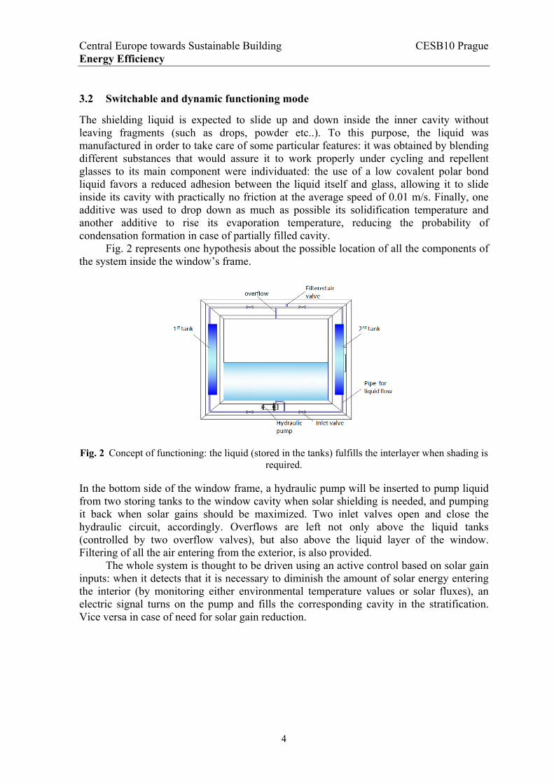
Fig. 2 represents one hypothesis about the possible location of all the components of the system inside the window’s frame.
Fig. 2 Concept of functioning: the liquid (stored in the tanks) fulfills the interlayer when shading is
required.
In the bottom side of the window frame, a hydraulic pump will be inserted to pump liquid from two storing tanks to the window cavity when solar shielding is needed, and pumping it back when solar gains should be maximized. Two inlet valves open and close the hydraulic circuit, accordingly. Overflows are left not only above the liquid tanks (controlled by two overflow valves), but also above the liquid layer of the window. Filtering of all the air entering from the exterior, is also provided.
The whole system is thought to be driven using an active control based on solar gain inputs: when it detects that it is necessary to diminish the amount of solar energy entering the interior (by monitoring either environmental temperature values or solar fluxes), an electric signal turns on the pump and fills the corresponding cavity in the stratification. Vice versa in case of need for solar gain reduction.
4
Central Europe towards Sustainable Building CESB10 Prague Energy Efficiency
4 Estimation of the glass stratification’s solar properties
4.1 Method for solar properties estimation
To accurately compare the thermal performances of the glass stratification under development with other typologies already commercialized, the spectral properties of several stratifications have been experimentally measured. Therefore the data of spectral properties have been measured.
The solar radiation has a spectral range from about 0.38·10-6 to 2.5·10-6 m. The range of wavelength of the solar radiation spectrum can be divided into the visible range (0.38–0.76·10-6 m) and the infrared range (0.76–3.5·10-6 m). The types of glass chosen for this experimental campaign are:
▪ one 6 mm thick single clear pane; ▪ one double clear glass stratification with a 8 mm thick air cavity (6+8+6); ▪ one triple clear glass stratification, having an 8 mm thick air cavity and a 1.5 mm
thick cavity filled with the shielding liquid described in section 3; ▪ one triple clear glass stratification, having an 8 mm thick air cavity and another
1.5 mm thick air cavity, simulating the case of layer not filled with the shielding liquid (i.e. glass stratification in its high transmittance mode).
The first two samples will act as benchmarks, while the third and fourth represent the two states of the novel stratification presented in this paper: shielded (i.e. low transmittance) and non shielded (i.e. high transmittance), respectively.
The spectral properties of glass (transmittance, absorbance, and reflectance) are the main properties that affect the solar and thermal performances of glass windows. For the purpose of solar shielding, the transmittance was thought to be the main spectral property to represent the characteristics of windows.
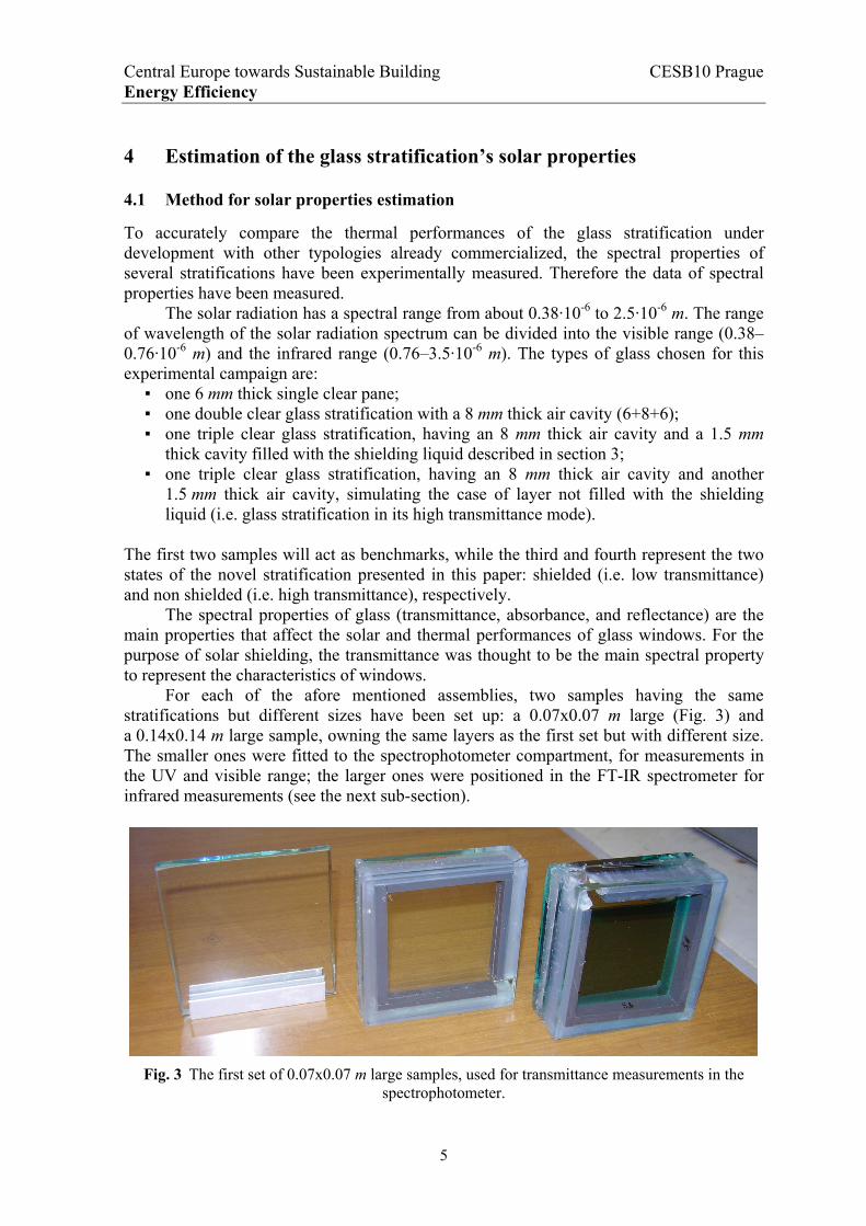
For each of the afore mentioned assemblies, two samples having the same stratifications but different sizes have been set up: a 0.07x0.07 m large (Fig. 3) and a 0.14x0.14 m large sample, owning the same layers as the first set but with different size. The smaller ones were fitted to the spectrophotometer compartment, for measurements in the UV and visible range; the larger ones were positioned in the FT-IR spectrometer for infrared measurements (see the next sub-section).
Fig. 3 The first set of 0.07x0.07 m large samples, used for transmittance measurements in the
spectrophotometer.
5

Central Europe towards Sustainable Building CESB10 Prague Energy Efficiency
4.2 Measurements
4.2.1 Experimental setup
The spectrophotometer (sample compartment depicted in Fig. 4-a) has been used to perform electronic spectroscopy in the UV range higher than 300 nm and in the visible one, in order to measure transmittance values to be successively used in the following eq. (1). Fig. 4-b shows the Near Infrared Fourier Transform spectrometer, which has been used to measure the infrared transmittance runnings of the four samples under testing. The two spectrometers were from Varian and Perkin Elmer, respectively.
a) b)
Fig. 4 Experimental setup used for transmittance coefficient estimation: smaller glass samples inserted in the spectrophotometer (a) and the larger ones inserted in the infrared Fourier Transform
spectrometer (b).
Given that experimental setup, it has been exploited to estimate the overall solar transmittance coefficient, which was computed on the basis of experimental records, according to UNI EN 410:2000 disposals. The solar reduction coefficient is defined as:
nm
nm
nm
nme
dS
dS
2500
300
2500
300
(1)
where Sλ is the spectral distribution relative to solar radiation, τλ is the solar reduction coefficient at the particular wavelength λ tabulated in the standard. In order to compute such values, experiments were carried out to measure each τλ.
4.2.2 Measurement results
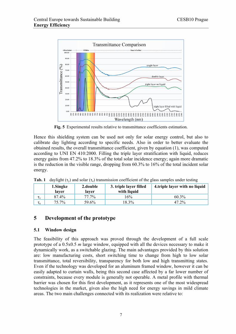
Fig. 5 shows the performances of the four stratifications tested, obtained through a fusion of the two sets of data recorded with the equipment described in the previous paragraph. It is worth noting that the triple stratification filled with liquid dramatically reduces transmission both in the visible range and in the infrared range. Its filtering properties in the visible interval are obviously determined by the liquid’s color (in this case green), instead in the infrared range the transmittance properties have been shown not to vary with color, but only with liquid’s thickness (in this case chosen equal to 0.0015 m).
6
Central Europe towards Sustainable Building CESB10 Prague Energy Efficiency
Fig. 5 Experimental results relative to transmittance coefficients estimation.
Hence this shielding system can be used not only for solar energy control, but also to calibrate day lighting according to specific needs. Also in order to better evaluate the obtained results, the overall transmittance coefficient, given by equation (1), was computed according to UNI EN 410:2000. Filling the triple layer stratification with liquid, reduces energy gains from 47.2% to 18.3% of the total solar incidence energy; again more dramatic is the reduction in the visible range, dropping from 60.3% to 16% of the total incident solar energy.
Tab. 1 daylight (τy) and solar (τe) transmission coefficient of the glass samples under testing
1.Singke layer
2.double layer
3. triple layer filled with liquid
4.triple layer with no liquid
τv 87.4% 77.7% 16% 60.3% τe 75.7% 59.6% 18.3% 47.2%
5 Development of the prototype
5.1 Window design
The feasibility of this approach was proved through the development of a full scale prototype of a 0.5x0.5 m large window, equipped with all the devices necessary to make it dynamically work, as a switchable glazing. The main advantages provided by this solution are: low manufacturing costs, short switching time to change from high to low solar transmittance, total reversibility, transparency for both low and high transmitting states. Even if the technology was developed for an aluminum framed window, however it can be easily adapted to curtain walls, being this second case affected by a far lower number of constraints, because every module is generally not operable. A metal profile with thermal barrier was chosen for this first development, as it represents one of the most widespread technologies in the market, given also the high need for energy savings in mild climate areas. The two main challenges connected with its realization were relative to:
7
Central Europe towards Sustainable Building CESB10 Prague Energy Efficiency
▪ producing a glass stratification for containing the liquid layer and fixing it in the metal frame;
▪ integrating an actuation and control systems in the window, which is able to turn on and off the shielding liquid, according to contingent specific needs.
In order to be convenient, the production of the new window should not require major modifications to window frames available in the market. For that reason, a commercially available aluminum frame was chosen, and all the actuation and control devices were designed to be inserted inside it.
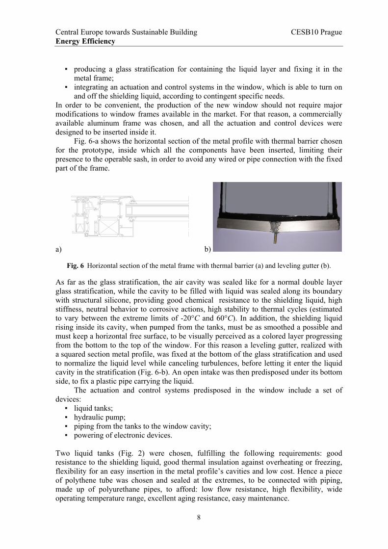
Fig. 6-a shows the horizontal section of the metal profile with thermal barrier chosen for the prototype, inside which all the components have been inserted, limiting their presence to the operable sash, in order to avoid any wired or pipe connection with the fixed part of the frame.
a) b)
Fig. 6 Horizontal section of the metal frame with thermal barrier (a) and leveling gutter (b).
As far as the glass stratification, the air cavity was sealed like for a normal double layer glass stratification, while the cavity to be filled with liquid was sealed along its boundary with structural silicone, providing good chemical resistance to the shielding liquid, high stiffness, neutral behavior to corrosive actions, high stability to thermal cycles (estimated to vary between the extreme limits of -20°C and 60°C). In addition, the shielding liquid rising inside its cavity, when pumped from the tanks, must be as smoothed a possible and must keep a horizontal free surface, to be visually perceived as a colored layer progressing from the bottom to the top of the window. For this reason a leveling gutter, realized with a squared section metal profile, was fixed at the bottom of the glass stratification and used to normalize the liquid level while canceling turbulences, before letting it enter the liquid cavity in the stratification (Fig. 6-b). An open intake was then predisposed under its bottom side, to fix a plastic pipe carrying the liquid.
The actuation and control systems predisposed in the window include a set of devices:
▪ liquid tanks; ▪ hydraulic pump; ▪ piping from the tanks to the window cavity; ▪ powering of electronic devices.
Two liquid tanks (Fig. 2) were chosen, fulfilling the following requirements: good resistance to the shielding liquid, good thermal insulation against overheating or freezing, flexibility for an easy insertion in the metal profile’s cavities and low cost. Hence a piece of polythene tube was chosen and sealed at the extremes, to be connected with piping, made up of polyurethane pipes, to afford: low flow resistance, high flexibility, wide operating temperature range, excellent aging resistance, easy maintenance.
8

Central Europe towards Sustainable Building CESB10 Prague Energy Efficiency
A micro-pump was chosen among two possible choices: a diaphragm pump (Fig. 7-a) and a centrifugal pump (Fig. 7-b). The first had a lower flow rate, but owned a very useful retained valve, and emitted lower noisy levels; the second one owned a higher flow rate, but had no retained valve and was noisier. Hence the first one was chosen to be inserted in the operable sash of the window. Finally, electric power was provided through a very low voltage supply (12 V) passing through the fixed frame and powering the micro-pump through metal electric connectors interposed in the window stop between the fixed and operable device (Fig. 7-c).
a) b) c)
Fig. 7 Diaphragm pump (a), centrifugal pump (b) and electric connectors for pump’s powering (c).
5.2 Window prototyping
All the components have then been assembled according to the schemes in Fig. 2 and in Fig. 8-a: the pump was placed in the bottom side and powered through a 12 V connection assembled in the fixed frame portion. The two tanks were inserted inside the two vertical jambs and the polyurethane pipes were allowed to pass along the entire perimeter to let both liquid and air to flow as needed. In Fig. 8-b one step of the procedure for pipe insertion is shown, where some holes were practiced at the corner of the frame’s structure, to let pipes go along the whole perimeter. The glass stratification was produced as described in the previous sub-section, equipped with the bottom leveling gutter, and fixed using standard methodologies.
a) b)
Fig. 8 Components positioning in the window (a) and one phase of its assembling (b).
Finally, the window shown in Fig. 9 was manufactured, being very similar to standard windows in its look, with the additional capability of changing its solar transmittance properties. The equipped window did not suffer a reduction of operability and was shown
9

Central Europe towards Sustainable Building CESB10 Prague Energy Efficiency
to work properly, like any standard window. The time lag required to fill the liquid cavity with the chosen pump was slightly longer than 10 min, which was intended to be acceptable. The retained valve was able to stop the liquid in the filled condition when needed and the electric bridge between the operable and fixed frames provided adequate performances, too. When the liquid was withdrawn, sliding at the same speed as in filling mode, no residual drops were left on the two glass panes.
a) b)
Fig. 9 Smart window’s prototype, in its non shielding (a) and shielding (b) working modes.
The only remark to be noted is that in the filled condition the hydrostatic pressure of the liquid caused a displacement in the middle of each glass pane, measured to be about 0.0016 m, that is to say comparable with the liquid cavity thickness: hence, further research will be undertaken in order to reduce such a deformation and to maintain a constant thickness of the liquid cavity layer, for example constraining it along the border, in order to cancel glass panes rotations.
6 Conclusions
The adoption of a smart window with a dynamic behavior, which exploits a shielding liquid layer sliding inside a cavity to provide solar control when needed, has been shown to be a feasible solution for the optimization of windows solar transmittance, also in the view of an automated control system.
In particular several experimental tests have been performed to estimate its shielding properties, highlighting a high transmittance reduction, as compared to the unshielded condition. Its switchable working mode gives it the capability to adequate its state to different weather conditions and, consequently, it can be easily adopted in mild climates and in a wide set of European countries.
Also the main technological challenges have been overcome, thanks to the production of the first experimental prototype, which was assembled through the use of commercial profiles and components. At least one concern for future research has been highlighted, being necessary to fix the glass stratification’s perimeter with a different solution, in order to constraint the glass plate against any rotation and reduce the deformation that the glass panes can undergo when filled with liquid, thus assuring a uniform thickness of the liquid cavity and also a uniform visible aspect.
10

Central Europe towards Sustainable Building CESB10 Prague Energy Efficiency
11
References
[1] ARTURAS KAKLAUSKAS, EDMUNDAS KAZIMIERAS ZAVADSKAS, SAULIUS RASLANAS, ROMUALDAS GINEVICIUS, ARUNAS KOMKA, PRANAS MALINAUSKAS, Selection of low-e windows in retrofit of public buildings by applying multiple criteria method COPRAS: A Lithuanian case, Energy and Buildings, vol. 38, p. 454–462, 2006.
[2] PAPAEFTHIMIOU, S., LEFTHERIOTIS, G., YIANOULIS, P., HYDE, T.J., EAMES, P.C., FANG, Y., PENNARUN, P.-Y., JANNASCH, P., Development of electrochromic evacuated advanced glazing, Energy and Buildings, Volume 38, Issue 12, December 2006, Pages 1455-1467.
[3] E.S. LEE, D.L. DIBARTOLOMEO, S.E. SELKOWITZ, Daylighting control performance of a thin-film ceramic electrochromic window: Field study results, Energy and Buildings, vol. 38, p. 30–44, 2006.
[4] A. PICCOLO, A. PENNISI, F. SIMONE, Daylighting performance of an electrochromic window in a small scale test-cell, Solar Energy, vol. 83, p. 832–844, 2009.
[5] WILSON, H. R., Steps towards Appropriate Accelerated Ageing Tests for Architectural Chromogenic Glazong, IEA SHC Task 27 Dissemination Workshop, Freiburg 2003.
[6] HEUSING, S., SUN, D.-L., OTERO-ANAYA, J., AEGERTER, M.A., Grey, brown and blue coloring sol-gel electrochromic devices, International journal of Thin Solid Films, vol. 502, p. 240 – 245, 2006.
[7] NITZ, P., HARTWIG, H., Solar control with thermotropic layers, Solar Energy, Volume 79, Issue 6, December 2005, Pages 573-582.
[8] REIM, M., KORNER, W., MANARA, J., KORDER, S., ARDUINI-SCHUSTER, M., EBERT, H.-P., FRICKE, J., Silica aerogel granulate material for thermal insulation and daylighting, Solar Energy, vol. 79, p. 131-139, 2005.
[9] KAMAL A.R. ISMAIL, CARLOS T. SALINAS, JORGE R. HENRIQUEZ, Comparison between PCM filled glass windows and absorbing gas filled windows, Energy and Buildings, vol. 40, p. 710–719, 2008.
[10] R. LOLLINI, L. DANZA, I. MERONI, Energy efficiency of a dynamic glazing system, Solar Energy, in press, available at www.elsevier.com/locate/solener, 2010.