smart solar carport system
TRANSCRIPT
College of Engineering
Department of Electrical Engineering
Spring 2019-2020
Senior Design Project
Final Report
SMART SOLAR CARPORT SYSTEM
In partial fulfillment of the requirements for the
Degree of Bachelor of Science in Electrical Engineering
Team Members
Student Name Student ID
1 Abdullah N. Al-Qahtani 201501245
2 Abdullah M. Al-Ghamdi 201402209
3 Abdulaziz A. Al-Abdulwahab 201602677
4 Saif F. Al-Sharif 201502262
Project Advisors:
Mr. Saifullah Shafiq
2 SMART SOLAR CARPORT PARKING SYSTEM
Abstract
The use of renewable energy sources, such as solar energy, is readily available to a wider
audience because of the falling costs of installing PV panels. Industrial sites and office
buildings provide a great potential for Photovoltaic (PV) panels with their large unused spaces
such as flat roofs or unshaded parking lots. For the non-commercial side, it includes homes,
universities, and marketplaces. Hence, the project of having smart solar carports system aims
to provide Prince Mohammad Bin Fahd University (PMU) with a modernized power system.
Furthermore, the project adopted the concept of renewable and green energy by generating
electricity and power from solar panels mounted on the carport. The designed solar carport
system composed of subsystems intended to provide smart solutions and integrate various
aspects in the world of smart electrical systems such as electrical vehicle (EV) charging system,
green home system, and local storage system. Green home is a building that aims to preserve
precious natural resources and improve our quality of life, and local storage to overcome
variation of power generated from PV panels.
3 SMART SOLAR CARPORT PARKING SYSTEM
Table of Contents
Abstract ............................................................................................................................................................... 2
1. Introduction .................................................................................................................................................... 5
1.1 Project Definition .................................................................................................................................. 5
1.2 Project Objectives ................................................................................................................................. 5
1.3 Project Specifications ............................................................................................................................ 6
1.4 Product Architecture and Components.................................................................................................. 6
1.5 Applications .......................................................................................................................................... 8
The main applications of smart solar carport system are as follows:.................................................................. 8
Provide renewable energy to PMU by generating solar power. ................................................................ 8
Provide electrical charging system for electrical vehicles (EV). ............................................................... 8
Power green homes via solar energy and battery bank. ............................................................................. 8
Provide battery bank system to have grid independent renewable system. ............................................... 8
2. Literature Review ........................................................................................................................................... 8
2.1 Project background................................................................................................................................ 8
2.2 Previous Work ....................................................................................................................................... 9
2.3 Comparative Study .............................................................................................................................. 14
3. System Design .............................................................................................................................................. 14
3.1 Design Constraints .............................................................................................................................. 14
3.1.1 Design Constraints: Sustainability .................................................................................................. 14
3.1.2 Design Constraints: Environmental ................................................................................................ 15
3.1.3 Design Constraints: Economic ........................................................................................................ 15
3.2 Design Methodology ........................................................................................................................... 16
3.3 Product Subsystems and Components ................................................................................................. 17
3.3.1 Product Subsystem1: Green home structure ................................................................................... 18
3.3.2 Product Subsystem2: Local storage system .................................................................................... 18
3.4 Implementation ................................................................................................................................... 18
4. System Testing and Analysis ........................................................................................................................ 32
4.1 Subsystem 1: Solar carport and green home ....................................................................................... 32
4.2 Subsystem 2: Electrical vehicle charger .............................................................................................. 35
4.3 Overall Results, Analysis and Discussion ........................................................................................... 38
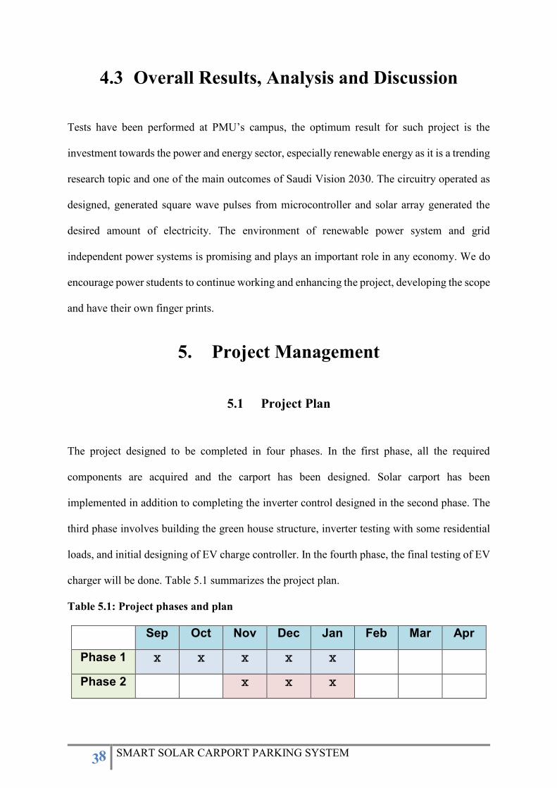
5. Project Management ..................................................................................................................................... 38
5.1 Project Plan .............................................................................................................................................. 38
5.2 Contribution of Team Members ................................................................................................................. 39
5.3 Project Execution Monitoring ............................................................................................................. 39
5.4 Challenges and Decision Making ........................................................................................................ 40
5.5 Project Bill of Materials and Budget ................................................................................................... 40
6. Project Analysis .......................................................................................................................................... 41
6.1 Life-long Learning .............................................................................................................................. 41
6.2 Impact of Engineering Solutions ......................................................................................................... 42
4 SMART SOLAR CARPORT PARKING SYSTEM
6.3 Contemporary Issues Addressed ......................................................................................................... 43
7. Conclusions and Future Recommendations .................................................................................................. 43
7.1 Conclusions ......................................................................................................................................... 43
7.2 Future Recommendations .................................................................................................................... 44
7.3 Future Work and Expected Final Prototype ........................................................................................ 44
7.4 Limitation and Challenges .................................................................................................................. 46
8. References .................................................................................................................................................... 47
Appendix A: Progress Reports ............................................................................................................................. 48
Appendix B: Bill of Materials .......................................................................................................................... 77
Appendix C: Datasheets ....................................................................................................................................... 78
Appendix D: Program Codes ................................................................................................................................ 80
5 SMART SOLAR CARPORT PARKING SYSTEM
1. Introduction
1.1 Project Definition
The project aims to provide renewable grid independent residential power system to Prince
Mohammad Bin Fahd University (PMU) which is a smart solar carport system. The project
adopts the concept of renewable and green energy by generating power and electricity via
photovoltaic array (PV) i.e. solar panels mounted on carport. The designed smart carport
system consists associated with subsystems such as electric vehicles (EV) charger, local storage
system, and green home system. The system intends to provide smart solutions and integrate
various aspects in the world of smart electrical systems and increase the electric mobility in
educational facilities. Green home is a building that aims to preserve precious natural resources
and improve the quality of life, in our project this will be established by solar energy to power
electrical households (residential loads).
1.2 Project Objectives
Enhance PMU reputation in the aspect of renewable energy and smart solutions by
generating renewable energy at PMU campus.
Reduce electricity expenditures and hedge against future cost increases, i.e. electric bills
Adopt and encourage environmentally-friendly transportation with electric vehicles and
their chargers in future, chiefly at educational facilities.
Improve parking experience for students, staff, and visitors.
Afford electric vehicle (EV) charging station.
Encourage environmentally-friendly transportation towards residential renewable system.
6 SMART SOLAR CARPORT PARKING SYSTEM
1.3 Project Specifications
Generates renewable energy using solar PV panels mounted on carport with maximum
output of 480 W.
Contains energy storage (battery) for 150 Ah, 12 V which acts as a backup source capable
to provide continuous power for 3.75 hours for maximum load of 480 W.
Charges Electrical Vehicle (EV) with charger output of 220 V.
Contains DC/AC Inverter with output of 75 W.
Energizes electrical household appliances (residential loads) up to 75 W.
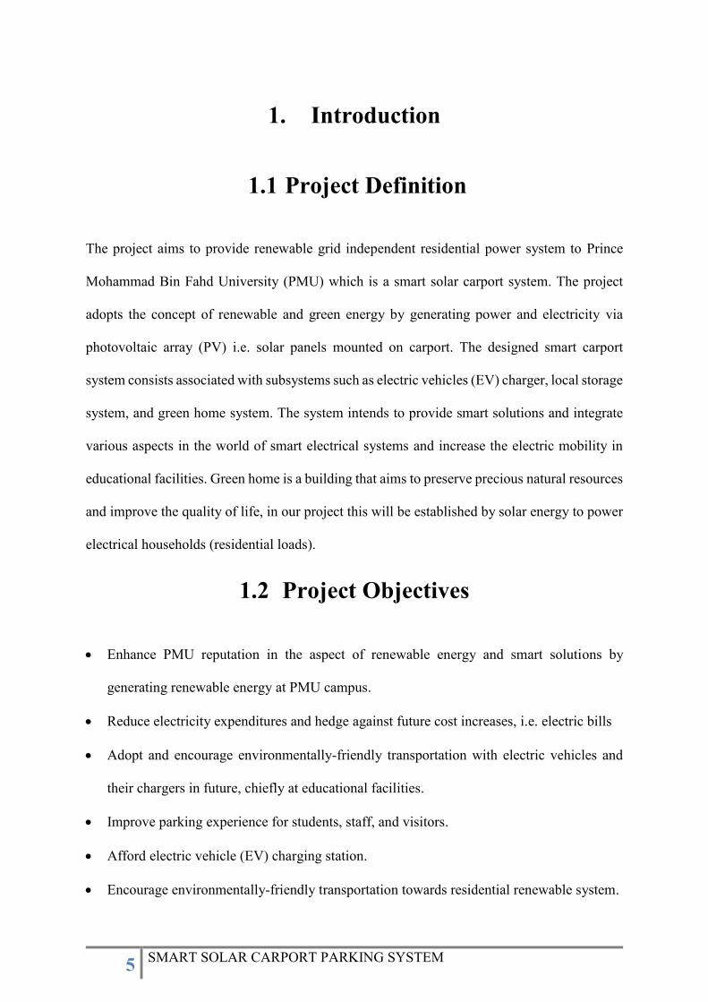
1.4 Product Architecture and Components
Figure 1.1: Block diagram of smart solar carport system.
The block diagram of the entire system is shown in Figure 1.1. It includes battery storage
system, DC/DC converter, and DC/AC inverter to convert the DC output of the solar panels to
AC in order to power up green home appliances. Sinusoidal pulse width modulation (SPWM)
technique will be used to perform DC to AC conversion. In this technique a sinusoidal
7 SMART SOLAR CARPORT PARKING SYSTEM
waveform is sampled, where each sample represents the percentage duty cycle of PWM. These
duty cycles are saved in the memory of the micro-controller as an array to make a look-up
table. Micro-controller utilizes stored duty cycles to generate gate control signals which are fed
to H-bridge inverter to obtain the desired output voltage and frequency signal. In addition to
powering up the green home, EV charging facility will be provisioned in the carport. The EV
charger will use voltage and current sensors to measure the charging current and voltage to
calculate the actual charging power. It will have the functionality of variable EV charging rates
which is currently nonexistent in the EV chargers available in the market
The primary benefit of having a solar carport is that it provides flexibility in the way of
customizing and design solar projects since the direction of solar panels and the angle at which
they are placed has a large impact on the amount of energy being produced. Hence, a solar
carport can be structured to optimize the positioning of solar panels, whereas this may not be
as simple for a rooftop solar panel system. Furthermore, the solar carport has been integrated
with a green home system and electric vehicle (EV) charger in order to encourage society
towards smart and green transformations and utilize renewable sources on daily applications
by which it increases the electric mobility. In addition, since the power being produced by solar
panels will be affected due to sunlight exposure, a local storage system (battery) has been used
to overcome the variation of power being produced by solar systems. It intends to funnelled
into the EV battery and power the green home loads after being processed by DC/AC inverter
and DC/DC converter and it is an important element to have self-independent (grid-
independent) power system. Overall, a solar carport gives a significant amount of flexibility
over how to use the solar energy and it is a greet option for residential and commercial
purposes.
8 SMART SOLAR CARPORT PARKING SYSTEM
1.5 Applications
The main applications of smart solar carport system are as follows:
Provide renewable energy to PMU by generating solar power.
Provide electrical charging system for electrical vehicles (EV).
Power green homes via solar energy and battery bank.
Provide battery bank system to have grid independent renewable system.
2. Literature Review
2.1 Project background
The information in this section carried out with the purpose of highlighting the importance of
renewable energy, solar systems, solar carports, and electrical vehicle (EV) charging systems.
Furthermore, the research findings intended to be utilized as sources of material, hence, only
similar and relevant projects that their scope corresponds with our scope will be analyzed and
discussed in this chapter.
The increasing adoption rate of renewable energy demand especially towards solar technology
has led to both surprising innovations as well as obvious and practical applications. One such
application of solar technology is found in solar carports. Solar carports are solar panels
mounted above car parking spaces and offer a flexible and cost-effective way to install solar
power as they do not require any extra space. Moreover, Solar carports are an offshoot of
traditional carports, which provide shade and protection for your vehicle by which the panels
9 SMART SOLAR CARPORT PARKING SYSTEM
themselves serve as a dual-purpose solution for both covering the owner’s vehicle and for
producing clean and renewable energy.
2.2 Previous Work
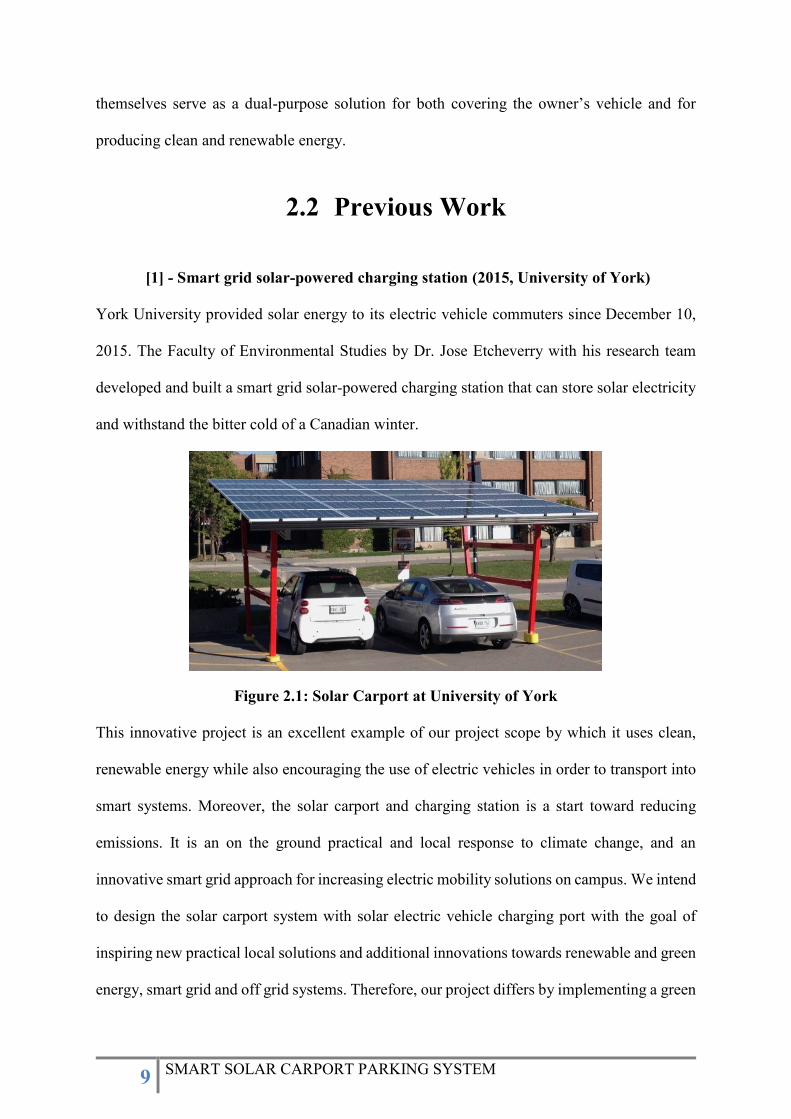
[1] - Smart grid solar-powered charging station (2015, University of York)
York University provided solar energy to its electric vehicle commuters since December 10,
2015. The Faculty of Environmental Studies by Dr. Jose Etcheverry with his research team
developed and built a smart grid solar-powered charging station that can store solar electricity
and withstand the bitter cold of a Canadian winter.
Figure 2.1: Solar Carport at University of York
This innovative project is an excellent example of our project scope by which it uses clean,
renewable energy while also encouraging the use of electric vehicles in order to transport into
smart systems. Moreover, the solar carport and charging station is a start toward reducing
emissions. It is an on the ground practical and local response to climate change, and an
innovative smart grid approach for increasing electric mobility solutions on campus. We intend
to design the solar carport system with solar electric vehicle charging port with the goal of
inspiring new practical local solutions and additional innovations towards renewable and green
energy, smart grid and off grid systems. Therefore, our project differs by implementing a green
10 SMART SOLAR CARPORT PARKING SYSTEM
house system in addition to battery bank system in order to overcome the variation of PV
production and charge EV’s more sufficiently.
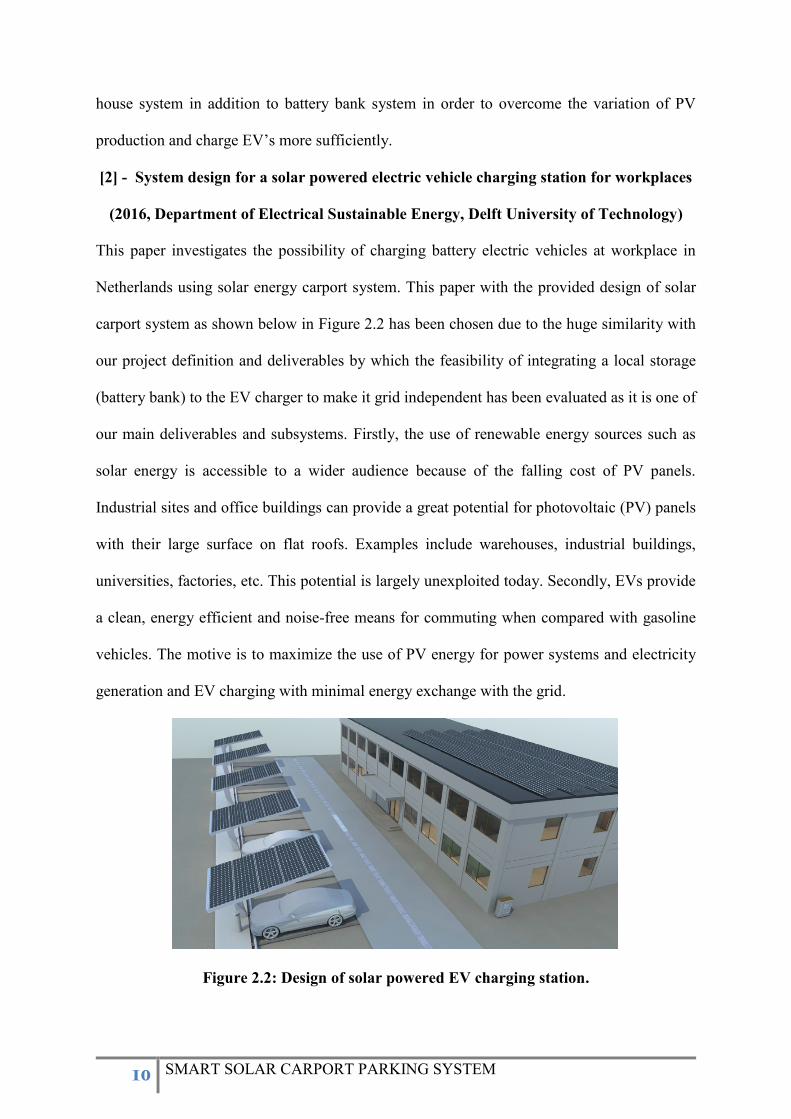
[2] - System design for a solar powered electric vehicle charging station for workplaces
(2016, Department of Electrical Sustainable Energy, Delft University of Technology)
This paper investigates the possibility of charging battery electric vehicles at workplace in
Netherlands using solar energy carport system. This paper with the provided design of solar
carport system as shown below in Figure 2.2 has been chosen due to the huge similarity with
our project definition and deliverables by which the feasibility of integrating a local storage
(battery bank) to the EV charger to make it grid independent has been evaluated as it is one of
our main deliverables and subsystems. Firstly, the use of renewable energy sources such as
solar energy is accessible to a wider audience because of the falling cost of PV panels.
Industrial sites and office buildings can provide a great potential for photovoltaic (PV) panels
with their large surface on flat roofs. Examples include warehouses, industrial buildings,
universities, factories, etc. This potential is largely unexploited today. Secondly, EVs provide
a clean, energy efficient and noise-free means for commuting when compared with gasoline
vehicles. The motive is to maximize the use of PV energy for power systems and electricity
generation and EV charging with minimal energy exchange with the grid.
Figure 2.2: Design of solar powered EV charging station.
11 SMART SOLAR CARPORT PARKING SYSTEM
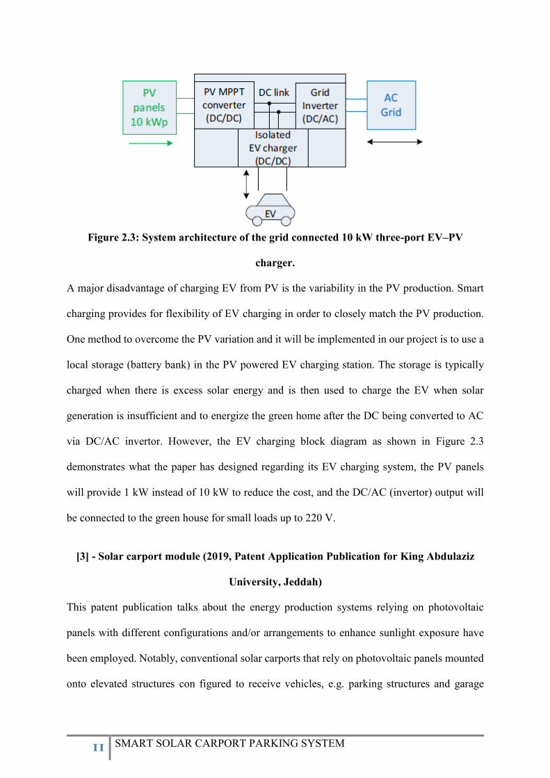
Figure 2.3: System architecture of the grid connected 10 kW three-port EV–PV
charger.
A major disadvantage of charging EV from PV is the variability in the PV production. Smart
charging provides for flexibility of EV charging in order to closely match the PV production.
One method to overcome the PV variation and it will be implemented in our project is to use a
local storage (battery bank) in the PV powered EV charging station. The storage is typically
charged when there is excess solar energy and is then used to charge the EV when solar
generation is insufficient and to energize the green home after the DC being converted to AC
via DC/AC invertor. However, the EV charging block diagram as shown in Figure 2.3
demonstrates what the paper has designed regarding its EV charging system, the PV panels
will provide 1 kW instead of 10 kW to reduce the cost, and the DC/AC (invertor) output will
be connected to the green house for small loads up to 220 V.
[3] - Solar carport module (2019, Patent Application Publication for King Abdulaziz
University, Jeddah)
This patent publication talks about the energy production systems relying on photovoltaic
panels with different configurations and/or arrangements to enhance sunlight exposure have
been employed. Notably, conventional solar carports that rely on photovoltaic panels mounted
onto elevated structures con figured to receive vehicles, e.g. parking structures and garage
12 SMART SOLAR CARPORT PARKING SYSTEM
roofs, to generate electricity while minimizing usable space occupied by the photovoltaic
panels have been adopted and explained in this paper in which it corresponds with our project
deliverables. This paper as well highlighted an obstacle that will occur with solar carport, the
photovoltaic panels may easily be covered by light obstructing materials, e.g. dust, sand, leaves,
and other debris, which can affect energy production, and cleaning and servicing these
photovoltaic panels may often be required. The publication claims are similar to our
deliverables as follows: a solar carport module comprising a support structure to provide shelter
to a vehicle, the support structure having a pair of trusses rotatable affixed to a ground surface
on which the vehicle is parked. Photovoltaic (PV) panels mounted above the carport (shelter)
to provide solar electricity. Battery assembly that electrically connects the plurality of
photovoltaic panel to receive, regulate, and store the solar electricity produced by PV panels.
The addition in our project will be in the EV charging system and green home system, instead
of just generating electricity, the produced energy intended to be utilized to charge EV vehicles
and energize a green home.
[4] - Integrated Energy Management of a Plug-in Electric Vehicle in Residential
Distribution Systems with Renewables (2017, Lorestani, A., Aghaee, S. S.,
Gharehpetian, G. B., & Ardehali, M. M.)
This paper illustrates microgrids, residential distribution, EV charging and renewable systems
and therefore highlighted the advantages of such systems. Integrating renewable energy
generation such as solar power into the existing power grid becomes more important nowadays.
Meanwhile, electric vehicles (EVs), particularly the plug-in electric vehicles (PEVs), for green
transportation have attracted increasing attention because of the intermittent nature of solar
power.
13 SMART SOLAR CARPORT PARKING SYSTEM
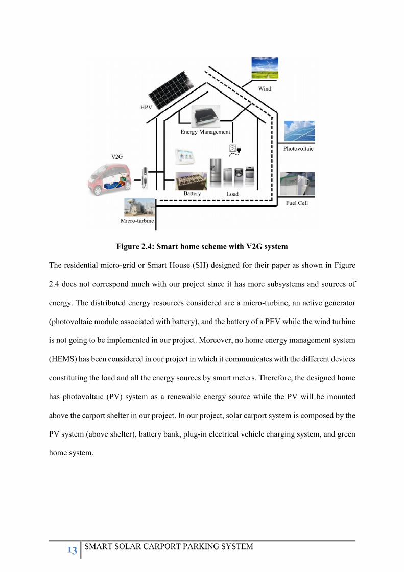
Figure 2.4: Smart home scheme with V2G system
The residential micro-grid or Smart House (SH) designed for their paper as shown in Figure
2.4 does not correspond much with our project since it has more subsystems and sources of
energy. The distributed energy resources considered are a micro-turbine, an active generator
(photovoltaic module associated with battery), and the battery of a PEV while the wind turbine
is not going to be implemented in our project. Moreover, no home energy management system
(HEMS) has been considered in our project in which it communicates with the different devices
constituting the load and all the energy sources by smart meters. Therefore, the designed home
has photovoltaic (PV) system as a renewable energy source while the PV will be mounted
above the carport shelter in our project. In our project, solar carport system is composed by the
PV system (above shelter), battery bank, plug-in electrical vehicle charging system, and green
home system.
14 SMART SOLAR CARPORT PARKING SYSTEM
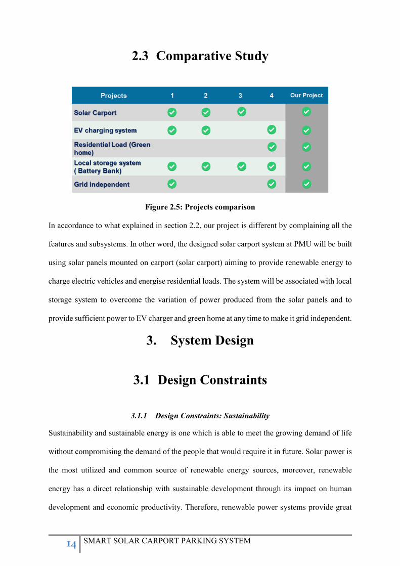
2.3 Comparative Study
Figure 2.5: Projects comparison
In accordance to what explained in section 2.2, our project is different by complaining all the
features and subsystems. In other word, the designed solar carport system at PMU will be built
using solar panels mounted on carport (solar carport) aiming to provide renewable energy to
charge electric vehicles and energise residential loads. The system will be associated with local
storage system to overcome the variation of power produced from the solar panels and to
provide sufficient power to EV charger and green home at any time to make it grid independent.
3. System Design
3.1 Design Constraints
3.1.1 Design Constraints: Sustainability
Sustainability and sustainable energy is one which is able to meet the growing demand of life
without compromising the demand of the people that would require it in future. Solar power is
the most utilized and common source of renewable energy sources, moreover, renewable
energy has a direct relationship with sustainable development through its impact on human
development and economic productivity. Therefore, renewable power systems provide great
15 SMART SOLAR CARPORT PARKING SYSTEM
opportunities in energy security and since renewable energy supplies are obtained naturally
from ongoing flows of energy in our surroundings, it should be sustainable. For renewable
energy to be sustainable, it must be limitless and provide non-harmful delivery of
environmental goods and service. The smart solar carport system is renewable and sustainable
energy source as a way of converting the sun energy into electrical energy, solar panels make
use of the single most sustainable resource on the planet which is the light of sun.
3.1.2 Design Constraints: Environmental
Solar energy creates clean, renewable power from the sun and benefits the environment.
Alternatives to fossil fuels reduce carbon footprint at home and abroad, reducing greenhouse
gases around the globe. Solar is known to have a favorable impact on the environment. Having
a solar carport system that can be used for residential and commercial purposes, can reduce
demand for fossil fuels, limit greenhouse gas emissions, and shrink the carbon footprint.
Therefore, the project encourages the society towards electric vehicles (EV’s) in which they
are better for the environment and emit less greenhouse gases and air pollutants over their life
than a petrol or diesel car.
3.1.3 Design Constraints: Economic
The smart solar carport system is an off-grid system i.e. not connected to the main grid. In this
system, the generated solar energy is stored in batteries and the DC power stored in the batteries
is converted into AC power by an inverter in order to energize the green home or any other
residential and commercial loads. Hence, the system is an excellent cost saving feature when
planned properly and is capable of reducing electricity bills. Moreover, using residential solar
power systems associated with electric vehicle charger can help reduce the costs of charging
an electric vehicle even further while simultaneously reducing fossil fuel consumption.
Combining the purchase of an electric car with the installation of a solar panel system allows
for even more savings throughout the lifetime of both the vehicle and the solar panel system.
16 SMART SOLAR CARPORT PARKING SYSTEM
In addition to reducing reliance on fossil fuels for charging, a solar panel system can offset
electricity costs and generate free energy.
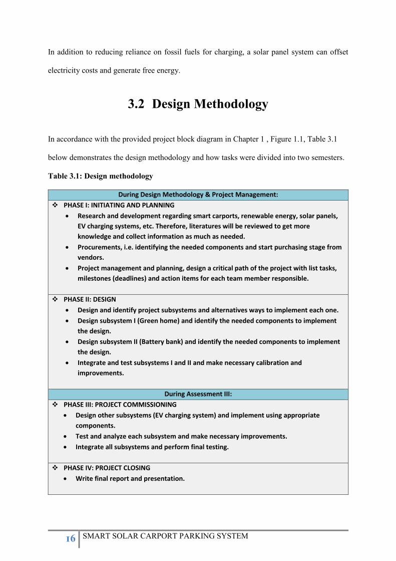
3.2 Design Methodology
In accordance with the provided project block diagram in Chapter 1 , Figure 1.1, Table 3.1
below demonstrates the design methodology and how tasks were divided into two semesters.
Table 3.1: Design methodology
During Design Methodology & Project Management:
PHASE I: INITIATING AND PLANNING
Research and development regarding smart carports, renewable energy, solar panels,
EV charging systems, etc. Therefore, literatures will be reviewed to get more
knowledge and collect information as much as needed.
Procurements, i.e. identifying the needed components and start purchasing stage from
vendors.
Project management and planning, design a critical path of the project with list tasks,
milestones (deadlines) and action items for each team member responsible.
PHASE II: DESIGN
Design and identify project subsystems and alternatives ways to implement each one.
Design subsystem I (Green home) and identify the needed components to implement
the design.
Design subsystem II (Battery bank) and identify the needed components to implement
the design.
Integrate and test subsystems I and II and make necessary calibration and
improvements.
During Assessment III:
PHASE III: PROJECT COMMISSIONING
Design other subsystems (EV charging system) and implement using appropriate
components.
Test and analyze each subsystem and make necessary improvements.
Integrate all subsystems and perform final testing.
PHASE IV: PROJECT CLOSING
Write final report and presentation.
17 SMART SOLAR CARPORT PARKING SYSTEM
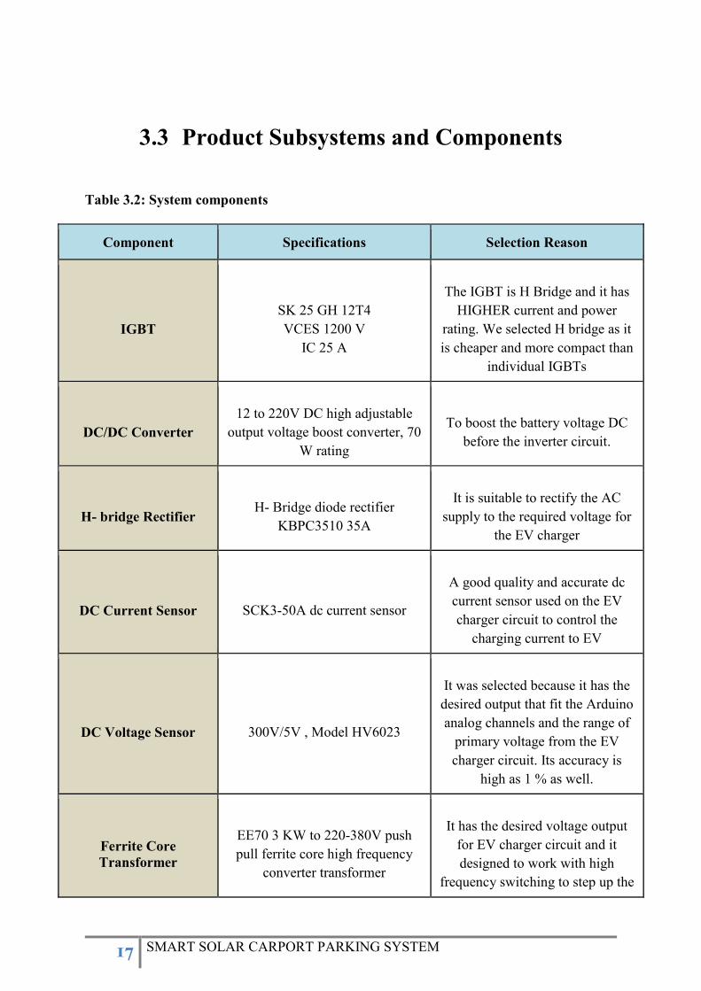
3.3 Product Subsystems and Components
Table 3.2: System components
Component Specifications Selection Reason
IGBT
SK 25 GH 12T4
VCES 1200 V
IC 25 A
The IGBT is H Bridge and it has
HIGHER current and power
rating. We selected H bridge as it
is cheaper and more compact than
individual IGBTs
DC/DC Converter
12 to 220V DC high adjustable
output voltage boost converter, 70
W rating
To boost the battery voltage DC
before the inverter circuit.
H- bridge Rectifier
H- Bridge diode rectifier
KBPC3510 35A
It is suitable to rectify the AC
supply to the required voltage for
the EV charger
DC Current Sensor
SCK3-50A dc current sensor
A good quality and accurate dc
current sensor used on the EV
charger circuit to control the
charging current to EV
DC Voltage Sensor
300V/5V , Model HV6023
It was selected because it has the
desired output that fit the Arduino
analog channels and the range of
primary voltage from the EV
charger circuit. Its accuracy is
high as 1 % as well.
Ferrite Core
Transformer
EE70 3 KW to 220-380V push
pull ferrite core high frequency
converter transformer
It has the desired voltage output
for EV charger circuit and it
designed to work with high
frequency switching to step up the
18 SMART SOLAR CARPORT PARKING SYSTEM
dc voltage and then rectify the
transformer output
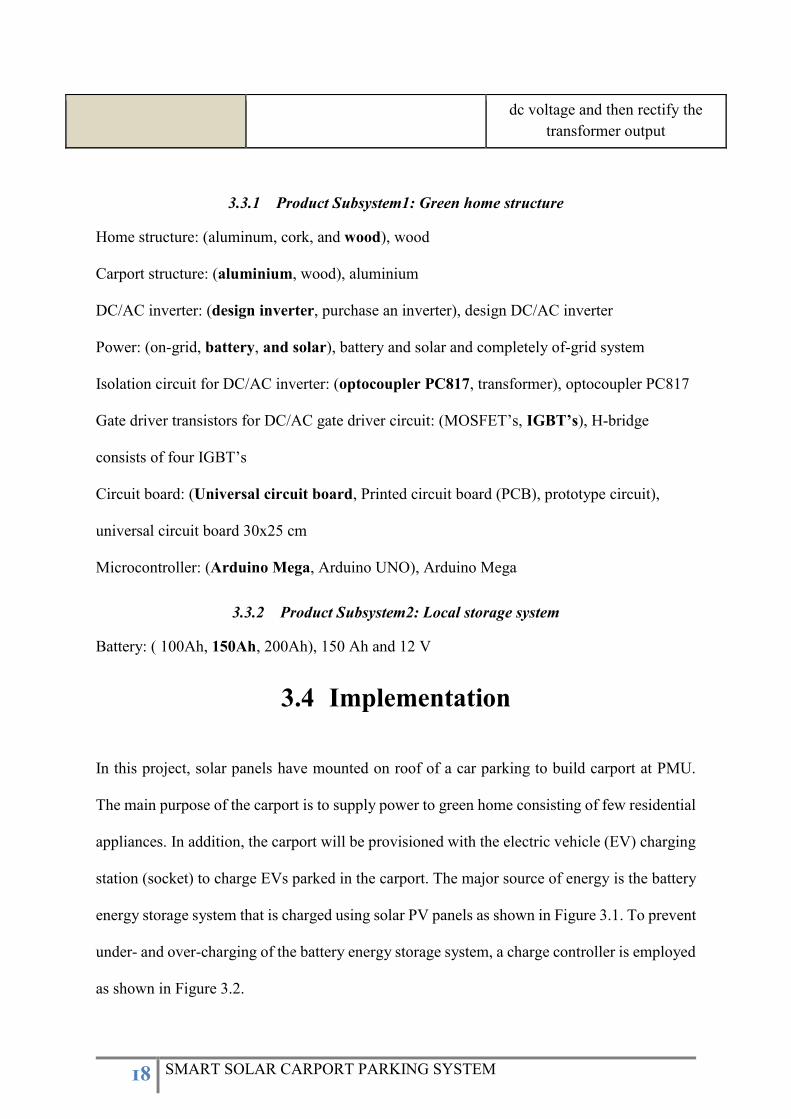
3.3.1 Product Subsystem1: Green home structure
Home structure: (aluminum, cork, and wood), wood
Carport structure: (aluminium, wood), aluminium
DC/AC inverter: (design inverter, purchase an inverter), design DC/AC inverter
Power: (on-grid, battery, and solar), battery and solar and completely of-grid system
Isolation circuit for DC/AC inverter: (optocoupler PC817, transformer), optocoupler PC817
Gate driver transistors for DC/AC gate driver circuit: (MOSFET’s, IGBT’s), H-bridge
consists of four IGBT’s
Circuit board: (Universal circuit board, Printed circuit board (PCB), prototype circuit),
universal circuit board 30x25 cm
Microcontroller: (Arduino Mega, Arduino UNO), Arduino Mega
3.3.2 Product Subsystem2: Local storage system
Battery: ( 100Ah, 150Ah, 200Ah), 150 Ah and 12 V
3.4 Implementation
In this project, solar panels have mounted on roof of a car parking to build carport at PMU.
The main purpose of the carport is to supply power to green home consisting of few residential
appliances. In addition, the carport will be provisioned with the electric vehicle (EV) charging
station (socket) to charge EVs parked in the carport. The major source of energy is the battery
energy storage system that is charged using solar PV panels as shown in Figure 3.1. To prevent
under- and over-charging of the battery energy storage system, a charge controller is employed
as shown in Figure 3.2.
19 SMART SOLAR CARPORT PARKING SYSTEM
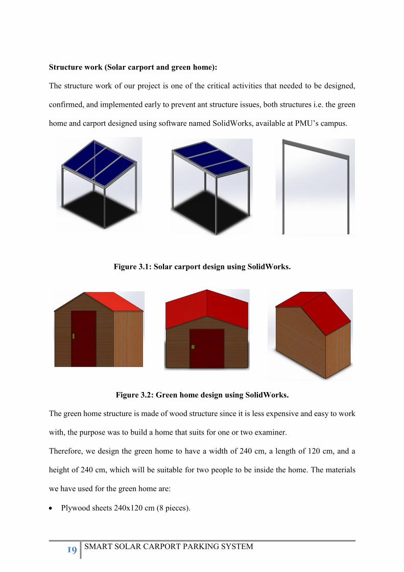
Structure work (Solar carport and green home):
The structure work of our project is one of the critical activities that needed to be designed,
confirmed, and implemented early to prevent ant structure issues, both structures i.e. the green
home and carport designed using software named SolidWorks, available at PMU’s campus.
Figure 3.1: Solar carport design using SolidWorks.
Figure 3.2: Green home design using SolidWorks.
The green home structure is made of wood structure since it is less expensive and easy to work
with, the purpose was to build a home that suits for one or two examiner.
Therefore, we design the green home to have a width of 240 cm, a length of 120 cm, and a
height of 240 cm, which will be suitable for two people to be inside the home. The materials
we have used for the green home are:
Plywood sheets 240x120 cm (8 pieces).
20 SMART SOLAR CARPORT PARKING SYSTEM
Pressure-Treated Lumber 220 cm (10 pieces).
Pressure-Treated Lumber 180 cm (10 pieces).
Screws.
The green home aims to show that we can energize it by our smart system. Therefore, we
decide to have different AC loads in the green home to be supplied. The total amount of the
load to be supplied is up to 75 W. The residential loads in the green home consist of:
LED Light (12 W).
Electric Fan (30 W).
Laptop Charger (30 W).
AC Power Sockets.
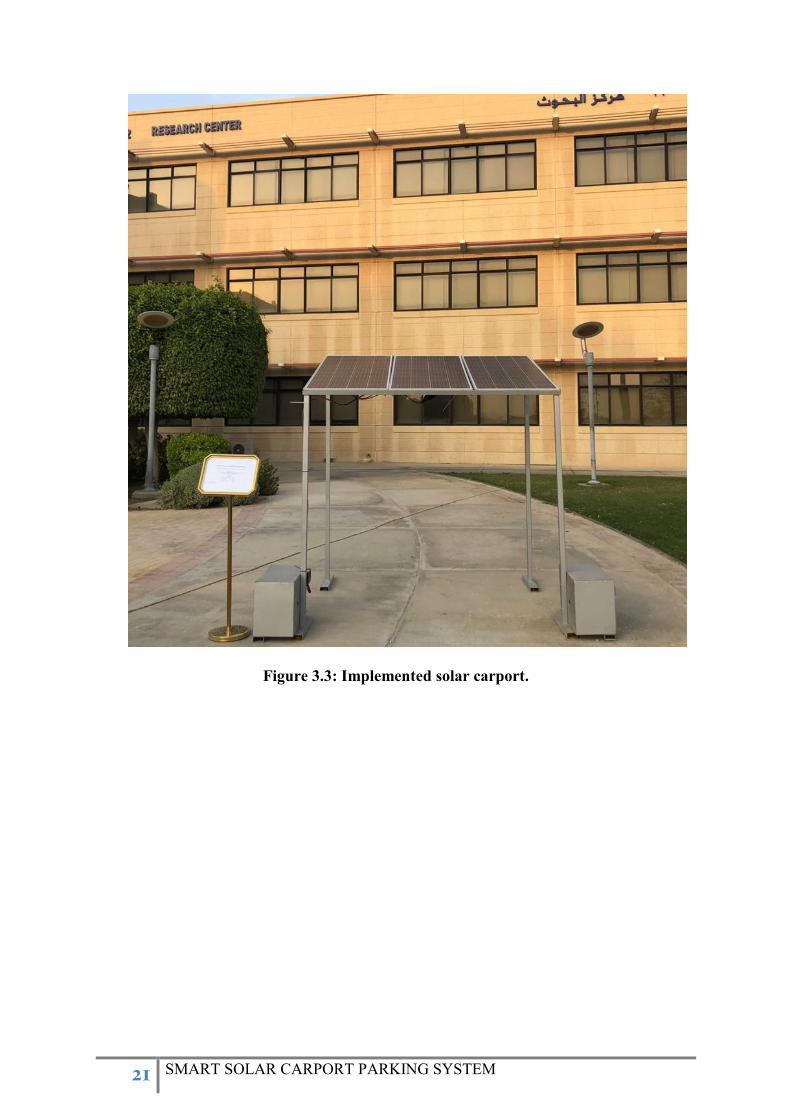
21 SMART SOLAR CARPORT PARKING SYSTEM
Figure 3.3: Implemented solar carport.
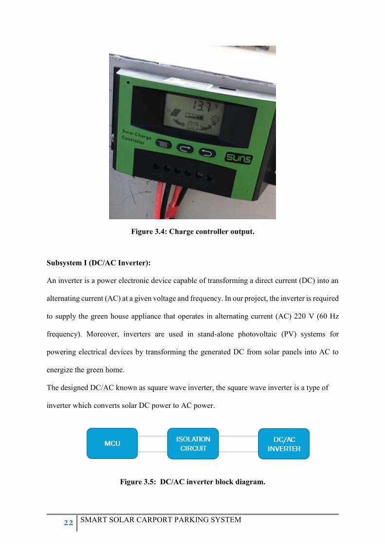
22 SMART SOLAR CARPORT PARKING SYSTEM
Figure 3.4: Charge controller output.
Subsystem I (DC/AC Inverter):
An inverter is a power electronic device capable of transforming a direct current (DC) into an
alternating current (AC) at a given voltage and frequency. In our project, the inverter is required
to supply the green house appliance that operates in alternating current (AC) 220 V (60 Hz
frequency). Moreover, inverters are used in stand-alone photovoltaic (PV) systems for
powering electrical devices by transforming the generated DC from solar panels into AC to
energize the green home.
The designed DC/AC known as square wave inverter, the square wave inverter is a type of
inverter which converts solar DC power to AC power.
Figure 3.5: DC/AC inverter block diagram.

23 SMART SOLAR CARPORT PARKING SYSTEM
The inverter inputs are square wave signals generated by the Microcontroller unit (MCU)
Arduino Mega by using the technique of pulse width modulation (PWM) in addition to an
isolation circuit followed by H-bridge consisting of four IGBT’s. Each IGBT intended to
operate as a voltage switche in accordance with the input signal. The use of IGBT’s in the
output stage and the PWM technology makes this inverter ideal for all types of loads. In
addition to the pulse width modulation, the protection part, i.e. isolation will be established by
using PC817 which is a 4 Pin optocoupler, normally used in embedded project for isolation
purposes.
24 SMART SOLAR CARPORT PARKING SYSTEM
Figure 3.6: Design of DC/AC gate driver circuit.
25 SMART SOLAR CARPORT PARKING SYSTEM
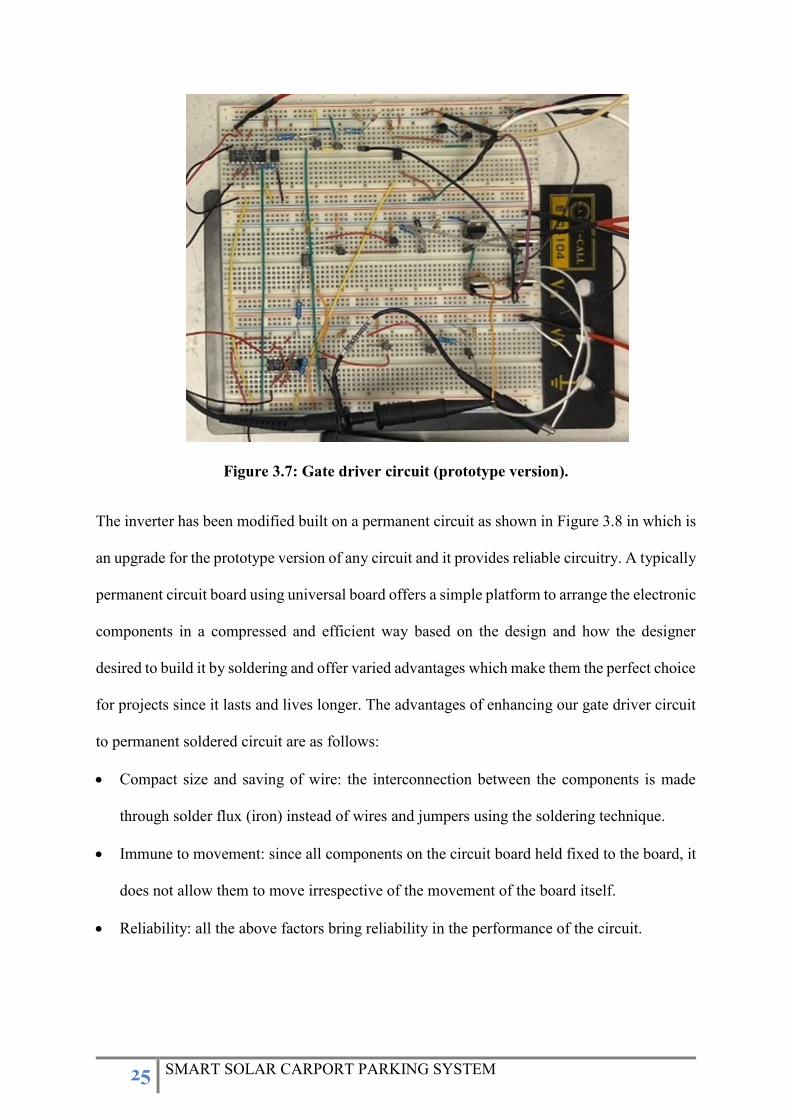
Figure 3.7: Gate driver circuit (prototype version).
The inverter has been modified built on a permanent circuit as shown in Figure 3.8 in which is
an upgrade for the prototype version of any circuit and it provides reliable circuitry. A typically
permanent circuit board using universal board offers a simple platform to arrange the electronic
components in a compressed and efficient way based on the design and how the designer
desired to build it by soldering and offer varied advantages which make them the perfect choice
for projects since it lasts and lives longer. The advantages of enhancing our gate driver circuit
to permanent soldered circuit are as follows:
Compact size and saving of wire: the interconnection between the components is made
through solder flux (iron) instead of wires and jumpers using the soldering technique.
Immune to movement: since all components on the circuit board held fixed to the board, it
does not allow them to move irrespective of the movement of the board itself.
Reliability: all the above factors bring reliability in the performance of the circuit.
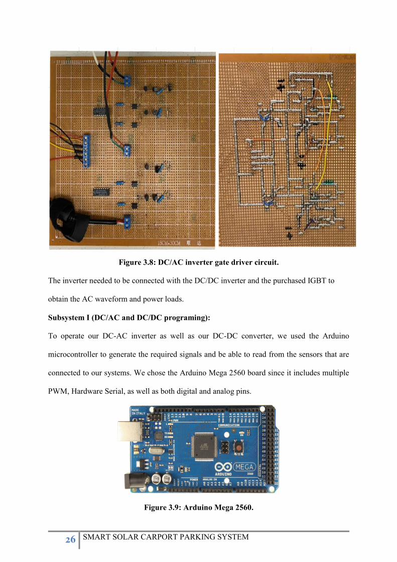
26 SMART SOLAR CARPORT PARKING SYSTEM
Figure 3.8: DC/AC inverter gate driver circuit.
The inverter needed to be connected with the DC/DC inverter and the purchased IGBT to
obtain the AC waveform and power loads.
Subsystem I (DC/AC and DC/DC programing):
To operate our DC-AC inverter as well as our DC-DC converter, we used the Arduino
microcontroller to generate the required signals and be able to read from the sensors that are
connected to our systems. We chose the Arduino Mega 2560 board since it includes multiple
PWM, Hardware Serial, as well as both digital and analog pins.
Figure 3.9: Arduino Mega 2560.
27 SMART SOLAR CARPORT PARKING SYSTEM
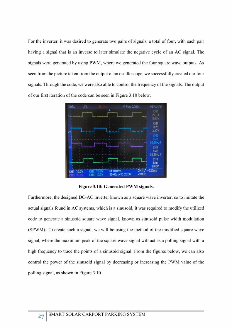
For the inverter, it was desired to generate two pairs of signals, a total of four, with each pair
having a signal that is an inverse to later simulate the negative cycle of an AC signal. The
signals were generated by using PWM, where we generated the four square wave outputs. As
seen from the picture taken from the output of an oscilloscope, we successfully created our four
signals. Through the code, we were also able to control the frequency of the signals. The output
of our first iteration of the code can be seen in Figure 3.10 below.
Figure 3.10: Generated PWM signals.
Furthermore, the designed DC-AC inverter known as a square wave inverter, so to imitate the
actual signals found in AC systems, which is a sinusoid, it was required to modify the utilized
code to generate a sinusoid square wave signal, known as sinusoid pulse width modulation
(SPWM). To create such a signal, we will be using the method of the modified square wave
signal, where the maximum peak of the square wave signal will act as a polling signal with a
high frequency to trace the points of a sinusoid signal. From the figures below, we can also
control the power of the sinusoid signal by decreasing or increasing the PWM value of the
polling signal, as shown in Figure 3.10.
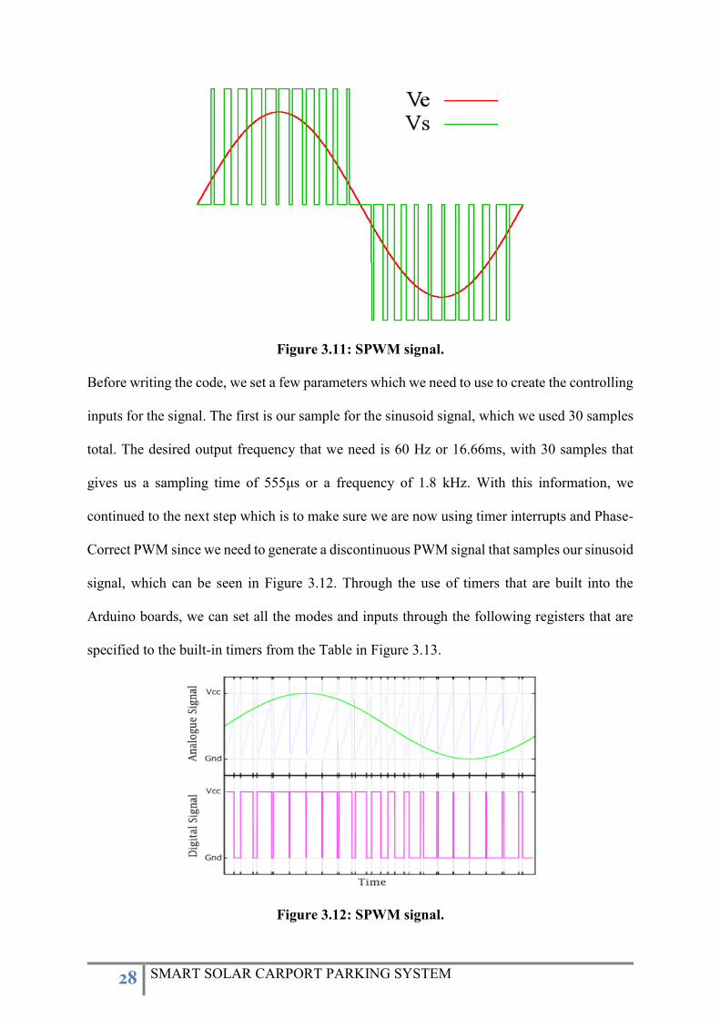
28 SMART SOLAR CARPORT PARKING SYSTEM
Figure 3.11: SPWM signal.
Before writing the code, we set a few parameters which we need to use to create the controlling
inputs for the signal. The first is our sample for the sinusoid signal, which we used 30 samples
total. The desired output frequency that we need is 60 Hz or 16.66ms, with 30 samples that
gives us a sampling time of 555μs or a frequency of 1.8 kHz. With this information, we
continued to the next step which is to make sure we are now using timer interrupts and Phase-
Correct PWM since we need to generate a discontinuous PWM signal that samples our sinusoid
signal, which can be seen in Figure 3.12. Through the use of timers that are built into the
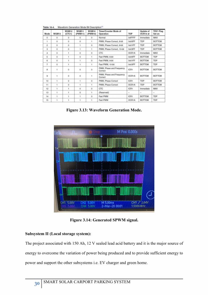
Arduino boards, we can set all the modes and inputs through the following registers that are
specified to the built-in timers from the Table in Figure 3.13.
Figure 3.12: SPWM signal.

29 SMART SOLAR CARPORT PARKING SYSTEM
TCCRx – Timer/Counter Control Register
TCNTx – Timer/Counter Register(Actual Timer Storage)
OCRxA/B/C – Output Compare Register
TIMSKx – Timer/Counter Interrupt Mask Register
TIFRx – Timer/Counter Interrupt Flag Register
The Overflow interrupt is the interrupt we chose since it coincides with our desired
functionality. The OVF interrupt uses the register named ICR, Input Capture Register. The
limit register that is being configured by us is ICRx register, which controls the value of which
the counting timer must stop and start again. Furthermore, the values that are being inputted to
the PWM registers are OCRxA and OCRxB where each register corresponds to the signal pairs.
To find the value of ICR register needed to acquire our sampling frequency, we used the
following equation:
𝐼𝐶𝑅𝑥 = 𝑓𝑐𝑙𝑘
(𝑓𝑑𝑒𝑠𝑖𝑟𝑒𝑑 − 1) × 𝑝𝑟𝑒𝑠𝑐𝑎𝑙𝑒𝑟
, where fclk is the Arduino Mega clock frequency, which is 16 MHz, and with our chosen set
prescaler of eight, we get the value of ICRx to be 1111. Since we are running four signals, the
value needed to be tuned to the final value of 555. Once we have calculated and set all the
parameters we rewrote the code to accommodate the change in functionality with the resulting
oscilloscope output shown in Figure 3.14.
30 SMART SOLAR CARPORT PARKING SYSTEM
Figure 3.13: Waveform Generation Mode.
Figure 3.14: Generated SPWM signal.
Subsystem II (Local storage system):
The project associated with 150 Ah, 12 V sealed lead acid battery and it is the major source of
energy to overcome the variation of power being produced and to provide sufficient energy to
power and support the other subsystems i.e. EV charger and green home.

31 SMART SOLAR CARPORT PARKING SYSTEM
Subsystem III (DC/DC converter for electrical vehicle charger):
DC-DC converters are power electronics devices known to either step up or step down the input
DC voltage into the desired DC output using semiconductors devices as switches. The dc-dc
converters can be divided into two main types: hard-switching pulse width modulation (PWM)
converters, and resonant and soft-switching converters. In this project, PWM dc-dc converters
have been chosen to be designed and utilized since they have been very popular for the last
three decades, and are widely used at all power levels. Advantages of PWM converters include
low component count, high efficiency, constant frequency operation, relatively simple control
and commercial availability of integrated circuit controllers, and ability to achieve high
conversion ratios for both step-down and step-up applications. A disadvantage of PWM dc-dc
converters is that PWM rectangular voltage and current waveforms cause turn-on and turn-off
losses in semiconductor devices, which limit practical operating frequencies to hundreds of
kilohertz. Rectangular waveforms also inherently generate EMI.
Hence, the EV charger can be built using a buck boost converter known as step-down converter
after rectifying the ac output obtained from subsystem I (Green home). Step-down choppers
find most of their applications in high performance dc drive systems, for example, electric
traction, electric vehicles, and machine tools. The dc motors with their winding inductances
and mechanical inertia act as filters resulting in high-quality armature currents. The average
output voltage of step-down choppers is a linear function of the switch duty ratio. The designed
dc-dc converter can be viewed as a dc transformer that delivers to the load a dc voltage or
current at a different level than the input source. This dc transformation is performed by
electronic switching means, not by electromagnetic means such as in conventional
transformers. The full-bridge converter is used at high (several kilowatts) power and voltage
levels. The voltage stress on power switches is limited to the input voltage source value. A
disadvantage of the full-bridge converter is a high number of semiconductor devices. The
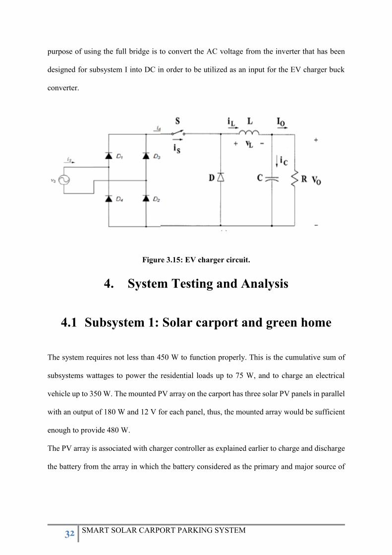
32 SMART SOLAR CARPORT PARKING SYSTEM
purpose of using the full bridge is to convert the AC voltage from the inverter that has been
designed for subsystem I into DC in order to be utilized as an input for the EV charger buck
converter.
Figure 3.15: EV charger circuit.
4. System Testing and Analysis
4.1 Subsystem 1: Solar carport and green home
The system requires not less than 450 W to function properly. This is the cumulative sum of
subsystems wattages to power the residential loads up to 75 W, and to charge an electrical
vehicle up to 350 W. The mounted PV array on the carport has three solar PV panels in parallel
with an output of 180 W and 12 V for each panel, thus, the mounted array would be sufficient
enough to provide 480 W.
The PV array is associated with charger controller as explained earlier to charge and discharge
the battery from the array in which the battery considered as the primary and major source of
33 SMART SOLAR CARPORT PARKING SYSTEM
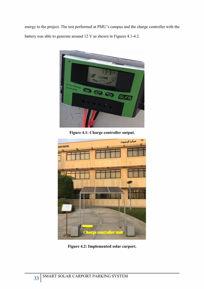
energy to the project. The test performed at PMU’s campus and the charge controller with the
battery was able to generate around 12 V as shown in Figures 4.1-4.2.
Figure 4.1: Charge controller output.
Figure 4.2: Implemented solar carport.

34 SMART SOLAR CARPORT PARKING SYSTEM
The DC/AC inverter has been tested as well at PMU’s lab, the DC/AC gate drive circuit has
successfully generated square waves from the utilized microcontroller (Arduino) in order to be
modulated and converted into Sinusoid Pulse Width Modulation (SPWM) signal as shown in
Figures 4.3-4.5.
Figure 4.3: DC/AC gate drive circuit output.
Figure 4.4: Generated Sinusoid using Arduino.
35 SMART SOLAR CARPORT PARKING SYSTEM
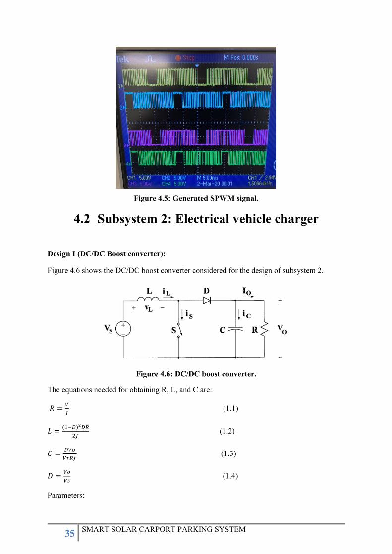
Figure 4.5: Generated SPWM signal.
4.2 Subsystem 2: Electrical vehicle charger
Design I (DC/DC Boost converter):
Figure 4.6 shows the DC/DC boost converter considered for the design of subsystem 2.
Figure 4.6: DC/DC boost converter.
The equations needed for obtaining R, L, and C are:
𝑅 =𝑉
𝐼 (1.1)
𝐿 =(1−𝐷)2𝐷𝑅
2𝑓 (1.2)
𝐶 =𝐷𝑉𝑜
𝑉𝑟𝑅𝑓 (1.3)
𝐷 =𝑉𝑜
𝑉𝑠 (1.4)
Parameters:

36 SMART SOLAR CARPORT PARKING SYSTEM
Vo max = 250 V
Vo min = 175 V
f= 45k Hz
Vr=1%
I max = 5 A
I min = 1 A
Calculations:
Using equation (1.1), the values of R are as follows:
𝑅 𝑚𝑖𝑛 =𝑉𝑜 𝑚𝑎𝑥
𝐼 𝑚𝑎𝑥=
250
5= 50 Ω
𝑅 𝑚𝑎𝑥 =𝑉𝑜 𝑚𝑖𝑛
𝐼 𝑚𝑖𝑛=
175
1= 175 Ω
Using equation 1.4, the values of D are as follows:
𝐷 𝑚𝑎𝑥 =𝑉𝑜 𝑚𝑎𝑥
𝑉𝑠=
250
12= 20.83
𝐷 𝑚𝑖𝑛 =𝑉𝑜 𝑚𝑖𝑛
𝑉𝑠=
175
12= 14.58
Using equation (1.2), the values of L are as follows:
𝐿 𝑚𝑎𝑥 =(1 − 𝐷𝑚𝑎𝑥)2𝐷𝑚𝑎𝑥𝑅𝑚𝑎𝑥
2𝑓=
(1 − 20.83)2(20.83)(175)
(2)(45𝑘)= 15.92 H
𝐿 𝑚𝑖𝑛 =(1 − 𝐷𝑚𝑖𝑛)2𝐷𝑚𝑖𝑛𝑅𝑚𝑖𝑛
2𝑓=
(1 − 14.58)2(14.58)(50)
(2)(45𝑘)= 1.55 H
Using equation (1.3), the values of C are as follows:
𝐶 𝑚𝑎𝑥 =𝐷𝑚𝑎𝑥𝑉𝑚𝑎𝑥
𝑉𝑟𝑅𝑚𝑎𝑥𝑓=
(20.83)(250)
(1%)(175)(45𝑘)= 66.12 𝑚F
𝐶 𝑚𝑖𝑛 =𝐷𝑚𝑖𝑛𝑉𝑚𝑖𝑛
𝑉𝑟𝑅𝑚𝑖𝑛𝑓=
(14.58)(175)
(1%)(50)(45𝑘)= 115.5 𝑚F
37 SMART SOLAR CARPORT PARKING SYSTEM
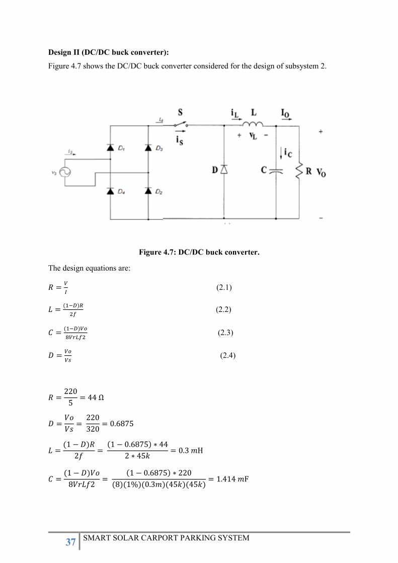
Design II (DC/DC buck converter):
Figure 4.7 shows the DC/DC buck converter considered for the design of subsystem 2.
Figure 4.7: DC/DC buck converter.
The design equations are:
𝑅 =𝑉
𝐼 (2.1)
𝐿 =(1−𝐷)𝑅
2𝑓 (2.2)
𝐶 =(1−𝐷)𝑉𝑜
8𝑉𝑟𝐿𝑓2 (2.3)
𝐷 =𝑉𝑜
𝑉𝑠 (2.4)
𝑅 =220
5= 44 Ω
𝐷 =𝑉𝑜
𝑉𝑠=
220
320= 0.6875
𝐿 =(1 − 𝐷)𝑅
2𝑓=
(1 − 0.6875) ∗ 44
2 ∗ 45𝑘= 0.3 𝑚H
𝐶 =(1 − 𝐷)𝑉𝑜
8𝑉𝑟𝐿𝑓2=
(1 − 0.6875) ∗ 220
(8)(1%)(0.3𝑚)(45𝑘)(45𝑘)= 1.414 𝑚F
38 SMART SOLAR CARPORT PARKING SYSTEM
4.3 Overall Results, Analysis and Discussion
Tests have been performed at PMU’s campus, the optimum result for such project is the
investment towards the power and energy sector, especially renewable energy as it is a trending
research topic and one of the main outcomes of Saudi Vision 2030. The circuitry operated as
designed, generated square wave pulses from microcontroller and solar array generated the
desired amount of electricity. The environment of renewable power system and grid
independent power systems is promising and plays an important role in any economy. We do
encourage power students to continue working and enhancing the project, developing the scope
and have their own finger prints.
5. Project Management
5.1 Project Plan
The project designed to be completed in four phases. In the first phase, all the required
components are acquired and the carport has been designed. Solar carport has been
implemented in addition to completing the inverter control designed in the second phase. The
third phase involves building the green house structure, inverter testing with some residential
loads, and initial designing of EV charge controller. In the fourth phase, the final testing of EV
charger will be done. Table 5.1 summarizes the project plan.
Table 5.1: Project phases and plan
Sep Oct Nov Dec Jan Feb Mar Apr
Phase 1 𝚡 𝚡 𝚡 𝚡 𝚡
Phase 2 𝚡 𝚡 𝚡
39 SMART SOLAR CARPORT PARKING SYSTEM
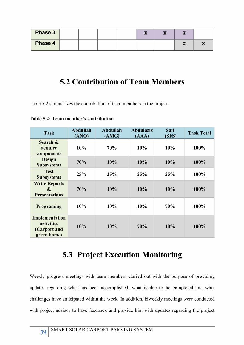
Phase 3 𝚡 𝚡 𝚡
Phase 4 𝚡 𝚡
5.2 Contribution of Team Members
Table 5.2 summarizes the contribution of team members in the project.
Table 5.2: Team member’s contribution
Task Abdullah
(ANQ)
Abdullah
(AMG)
Abdulaziz
(AAA)
Saif
(SFS) Task Total
Search &
acquire
components
10% 70% 10% 10% 100%
Design
Subsystems 70% 10% 10% 10% 100%
Test
Subsystems 25% 25% 25% 25% 100%
Write Reports
&
Presentations
70% 10% 10% 10% 100%
Programing 10% 10% 10% 70%
100%
Implementation
activities
(Carport and
green home)
10% 10% 70% 10% 100%
5.3 Project Execution Monitoring
Weekly progress meetings with team members carried out with the purpose of providing
updates regarding what has been accomplished, what is due to be completed and what
challenges have anticipated within the week. In addition, biweekly meetings were conducted
with project advisor to have feedback and provide him with updates regarding the project

40 SMART SOLAR CARPORT PARKING SYSTEM
progress and to discuss the remaining tasks. Lastly, WhatsApp group has been created and all
parties have been added (students and advisor) for easy access and quick response.
5.4 Challenges and Decision Making
The main challenge that has been faced is shipments’ delays due to coronavirus (COVID-19).
Unfortunately, the Saudi market with its key player vendors has a lack of power electronics
components such as DC/DC converters, DC/AC inverters, IGBT etc. Hence, most of the project
procurements were ordered from abroad, mostly from China. As a result of COVID-19, the
shipments got delayed for more than two and a half months.
Accordingly, to overcome the spreading of coronavirus, schools have suspended till further
notice and we were under quarantine, which has a significant impact in our progress by which
we could not either conduct meetings nor implement and test the project.
Another challenge has to be acknowledged is the background information regarding power
electronics. As explained, most of the designed and integrated subsystems are directly linked
to power electronics which are unfortunately not listed so far in the study plan for electrical
engineering students.
Moreover, two of the subsystems required manpower to be installed i.e., solar carport and green
home structure. The group faced difficulties to have support from PMU maintenance
department with its representatives to support us regarding the implementation of our work.
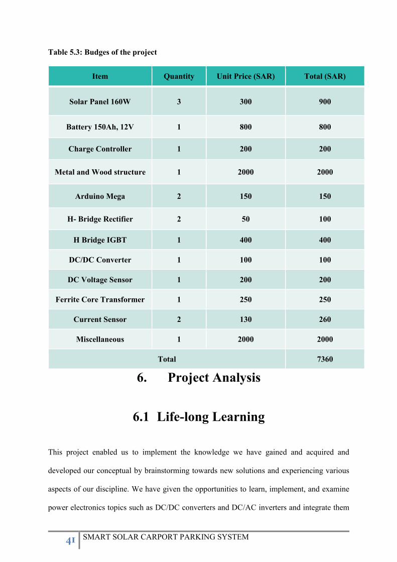
5.5 Project Bill of Materials and Budget
Table 5.3 summarizes the budges of the project.
41 SMART SOLAR CARPORT PARKING SYSTEM
Table 5.3: Budges of the project
Item Quantity Unit Price (SAR) Total (SAR)
Solar Panel 160W 3 300 900
Battery 150Ah, 12V 1 800 800
Charge Controller 1 200 200
Metal and Wood structure 1 2000 2000
Arduino Mega 2 150 150
H- Bridge Rectifier 2 50 100
H Bridge IGBT 1 400 400
DC/DC Converter 1 100 100
DC Voltage Sensor 1 200 200
Ferrite Core Transformer 1 250 250
Current Sensor 2 130 260
Miscellaneous 1 2000 2000
Total 7360
6. Project Analysis
6.1 Life-long Learning
This project enabled us to implement the knowledge we have gained and acquired and
developed our conceptual by brainstorming towards new solutions and experiencing various
aspects of our discipline. We have given the opportunities to learn, implement, and examine
power electronics topics such as DC/DC converters and DC/AC inverters and integrate them
42 SMART SOLAR CARPORT PARKING SYSTEM
to come up with new solutions that lead to the specification and the project scope. Therefore,
we had the chance to design, build, and program our own circuits using permanent breadboards
and Arduino platforms in which it leaded us to face new challenges and gained more experience
and knowledge. In addition, the project has a significant influence and developed our research
skills. Different types of project management, self-learning, time management, and cost
management techniques have been used.
6.2 Impact of Engineering Solutions
According to the Saudi Vision 2030, a massive number of renewable energy resources will be
utilized and installed in the coming few years. The renewable energy sources, such as, Solar
PV and Wind Turbines are sporadic in nature since they depend on climatic conditions. To
cope with their intermittent nature, battery energy storage systems are required to provide the
necessary support when there is a fluctuation in power generation from renewable sources. The
electric vehicles can thus provide energy to grid operating in a vehicle-to-grid (V2G) mode.
Currently, the number of electric vehicles in Saudi Arabia is very low. Therefore, only two EV
chargers have been installed in the whole kingdom so far. However, electric vehicles will
become ubiquitous in the near future since they have received international acceptance. The
large-scale integration of electric vehicles into the grid requires extensive investigation. Hence,
with the completion of this project, the project can play a key role towards Vision 2030 by
implementing grid independent renewable energy systems on the residential scale and examine
controllable charging rate EV chargers. Thus, research on controlling the charging rates of
electric vehicles can assist in accommodating high penetration level of renewable energy
resources into the grid without negative impacts.

43 SMART SOLAR CARPORT PARKING SYSTEM
6.3 Contemporary Issues Addressed
There are many issues that are addressed in our project for Saudi Arabia and worldwide such
as introducing simple EV charger solution that can be available at private and public parking
lots. Moreover, it solves the issue of un-utilized parking spaces for both residential and
commercial entities to generate power from renewable energy, hence, it reduces grid demand
and uses more nature source (solar energy).
7. Conclusions and Future Recommendations
7.1 Conclusions
The scope of this project and our optimum goal was to design and provide a grid independent
smart solar carport parking system that generates renewable energy to power green home and
charge electric vehicles. This has been established by mounting a PV array (3x1), three panels
in parallel on a carport, the system integrated with battery in order to be grid independent
system.
We would like to thank the efficient faculty and staff of Electrical Engineering Department at
Prince Mohammad Bin Fahd University for their continuous support. Their efforts allowed us
to experience remarkable senior project within the field of our interest. Moreover, we would
like to thank our project advisor, Mr. Saifullah Shafiq for his kind guidance, support, and the
knowledge he shared with us.
We could not have completed this senior project, nor any course of our degree, without the
assist, love, and support from all who ever taught us including our teachers, instructors and
professors.
44 SMART SOLAR CARPORT PARKING SYSTEM
7.2 Future Recommendations
In future, a fully solar powered electric vehicle along with autonomous charge controller can
be designed in collaboration with Mechanical Engineering and Computer Science
Departments. Also, some machine learning techniques can be used to improve the performance
of EV charger.
7.3 Future Work and Expected Final Prototype
The team successfully designed all subsystems and completed procurements stages and
received all required equipment and components in order to perform the final implementation
and integration process of subsystems. The remaining tasks are integrating the purchased H-
bridge IGBT to be connected with the DC/AC inverter as a final step to obtain AC waveform.
After soldering IGBT with gate driver circuit (DC/AC inverter), the output is taken to the
designed green home. The green home designed to be wood structure with residential loads up
to 75 W associated with energy system (Battery) 150 Ah, 12 V. Moreover, the DC/DC
converter needed to be implemented with the purchased full bridge, the converter output is
taken from DC/AC inverter in order to have grid independent (stand-alone) project, the
converter chosen to be buck converter intends to step down the voltage into 175 V which is the
required level to charge the electrical vehicle.
The remaining tasks estimated to be completed within one and half week. The final prototype
was planned to have the green home structure next to the implemented carport and the electric
vehicle (EV) was planned to park inside the carport.

45 SMART SOLAR CARPORT PARKING SYSTEM
The performed tasks and designed subsystems are efficient to eventually met the specifications
and project deliverables as follows:
Generates renewable energy using solar PV panels mounted on carport with maximum
output of 480 W.
Contains energy storage (battery) for 150 Ah, 12 V which acts as a backup source capable
to provide continuous power for 3.75 hours for maximum load of 480 W.
Charges Electrical Vehicle (EV) with charger output of 220 V.
Contains DC/AC Inverter with output of 75 W.
Energizes electrical household appliances (residential loads) up to 75 W.
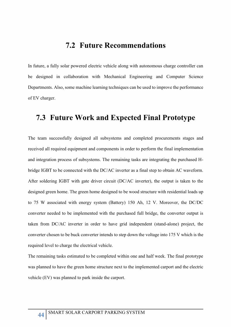
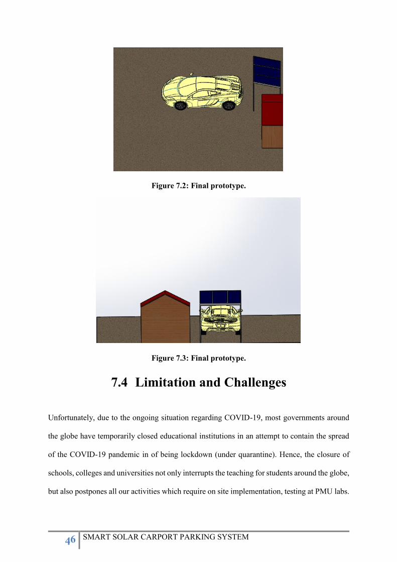
Figures 7.1-7.3 illustrate the expected final prototype of the project after implementing all
sybsystems.
Figure 7.1: Final prototype.
46 SMART SOLAR CARPORT PARKING SYSTEM
Figure 7.2: Final prototype.
Figure 7.3: Final prototype.
7.4 Limitation and Challenges
Unfortunately, due to the ongoing situation regarding COVID-19, most governments around
the globe have temporarily closed educational institutions in an attempt to contain the spread
of the COVID-19 pandemic in of being lockdown (under quarantine). Hence, the closure of
schools, colleges and universities not only interrupts the teaching for students around the globe,
but also postpones all our activities which require on site implementation, testing at PMU labs.
47 SMART SOLAR CARPORT PARKING SYSTEM
Fortunately, the Electrical Engineering Department at Prince Mohammad Bin Fahd University
adopted virtual meetings and online classes from the first day of the pandemic scenario via
blackboard, but still we could not complete or progress our project further.
8. References
1. Sandramc. (2017, September 26). Environmentally-friendly vehicles get a charge out
of York University. Retrieved September 30, 2019, from
https://news.yorku.ca/2015/12/09/york-u-unveils-first-solar-charging-station-for-
electric-vehicles/.
2. Mouli, G. C., Bauer, P., & Zeman, M. (2016). System design for a solar powered
electric vehicle charging station for workplaces. Applied Energy, 168, 434–443. doi:
10.1016/j.apenergy.2016.01.110
3. US20190068111A1 - Solar carport module. (0AD). Retrieved September 27, 2019,
from https://patents.google.com/patent/US20190068111A1/en.
4. Lorestani, A., Aghaee, S. S., Gharehpetian, G. B., & Ardehali, M. M. (2017). Energy
management in smart home including PV panel, battery, electric heater with
integration of plug-in electric vehicle. 2017 Smart Grid Conference (SGC). doi:
10.1109/sgc.2017.8308855
5. Rashid, M. H. (2014). Power electronics handbook: devices, circuits, and
applications. Upper Saddle River, NJ: Prentice Hall.
48 SMART SOLAR CARPORT PARKING SYSTEM
Appendix A: Progress Reports
Prince Mohammad Bin Fahd University (PMU)
Department of Electrical Engineering
Design Methodology & Project Management
Instructor: Dr. Samir El-Nakla
FALL 2019/2020
PROJECT PROGRESS REPORT I
SMART SOLAR CARPORT SYSTEM AT PMU
TEAM MEMBER:
Abdullah N. Al-Qahtani (Project Leader) 201501245
Abdullah M. Al-Ghamdi 201402209
Abdulaziz A. Al-Abdulwahab 201602677
Saif F. Al-Sharif 201502262
PROJECT ADVISOR
Mr. Saifullah Shafiq
Date October 14, 2019

49 SMART SOLAR CARPORT PARKING SYSTEM
This paper intended to provide a progress report and it briefly illustrates the performed tasks
regarding the project of smart solar carport system at Prince Mohammad Bin Fahd University
(PMU) starting from week one till October 14th, 2019
PERFORMED TASKS AND ACTIVITIES
Weekly progress meetings: The weekly progress meeting is one way of keeping in touch
with the project advisor, team members. These meetings are intended to ensure a project
stays on track and to give team members the chance to intervene early if problems arise.
These meetings have specific agenda to assure that everything is working just fine and the
entire project team is following the schedule that they need to religiously consider. The
weekly progress meetings during the project work will be held at the same time and on the
same day each week that is on Tuesday at 7 pm. Several meetings have been conducted
with Mr. Shafiq and all members have participated. These meetings carried out with the
purpose of introducing the team and our topics that correspond with our interest, deciding
and finalizing the topic, identify the system and subsystems and lastly but most importantly,
discuss the progress of the project.
Project proposal: Typically, a project proposal is the initial framework for establishing
the concept of the project and includes what is required to accomplish, an explanation of
objectives, and plans for achieving them. It is common for a project proposal in the
engineering environment to include a block diagram and specifications to illustrate the
significance of this specific project idea, and explain the origins of the project.
Develop project critical path activities table: In project management, a critical path is
the sequence of project network activities which add up to the longest overall duration,
regardless if that longest duration has float or not. Therefore, critical path analysis is
commonly used with all forms of projects, including construction, software development,
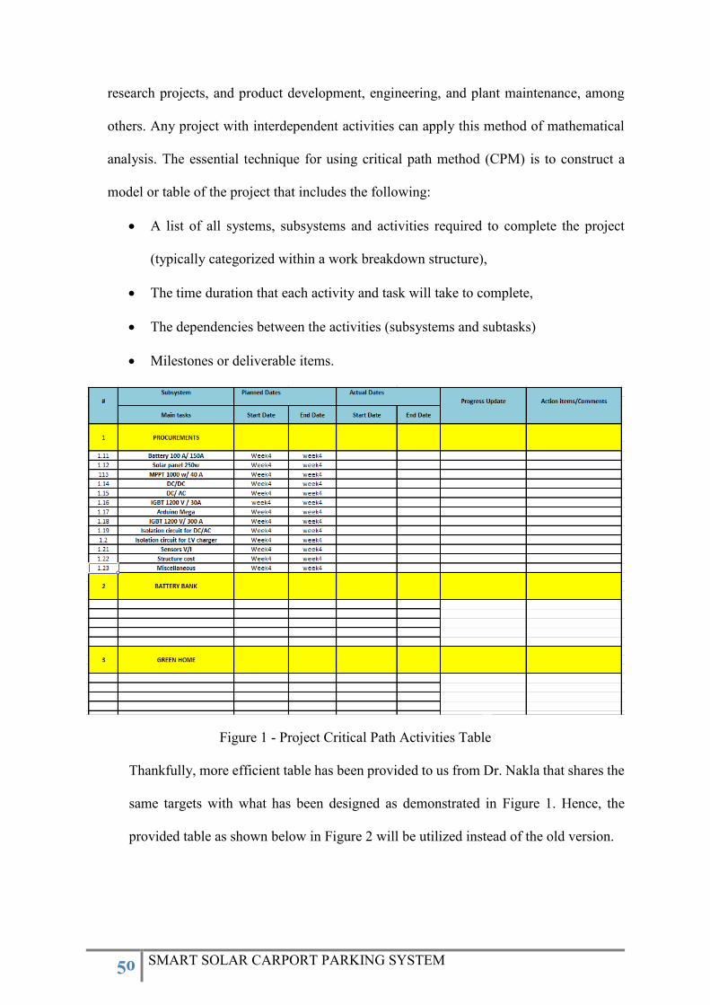
50 SMART SOLAR CARPORT PARKING SYSTEM
research projects, and product development, engineering, and plant maintenance, among
others. Any project with interdependent activities can apply this method of mathematical
analysis. The essential technique for using critical path method (CPM) is to construct a
model or table of the project that includes the following:
A list of all systems, subsystems and activities required to complete the project
(typically categorized within a work breakdown structure),
The time duration that each activity and task will take to complete,
The dependencies between the activities (subsystems and subtasks)
Milestones or deliverable items.
Figure 1 - Project Critical Path Activities Table
Thankfully, more efficient table has been provided to us from Dr. Nakla that shares the
same targets with what has been designed as demonstrated in Figure 1. Hence, the
provided table as shown below in Figure 2 will be utilized instead of the old version.
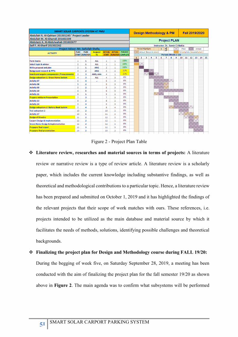
51 SMART SOLAR CARPORT PARKING SYSTEM
Figure 2 - Project Plan Table
Literature review, researches and material sources in terms of projects: A literature
review or narrative review is a type of review article. A literature review is a scholarly
paper, which includes the current knowledge including substantive findings, as well as
theoretical and methodological contributions to a particular topic. Hence, a literature review
has been prepared and submitted on October 1, 2019 and it has highlighted the findings of
the relevant projects that their scope of work matches with ours. These references, i.e.
projects intended to be utilized as the main database and material source by which it
facilitates the needs of methods, solutions, identifying possible challenges and theoretical
backgrounds.
Finalizing the project plan for Design and Methodology course during FALL 19/20:
During the begging of week five, on Saturday September 28, 2019, a meeting has been
conducted with the aim of finalizing the project plan for the fall semester 19/20 as shown
above in Figure 2. The main agenda was to confirm what subsystems will be performed
52 SMART SOLAR CARPORT PARKING SYSTEM
and accomplished during this semester. In addition, we have identified the subtasks and
activities that are required to complete each subsystem.
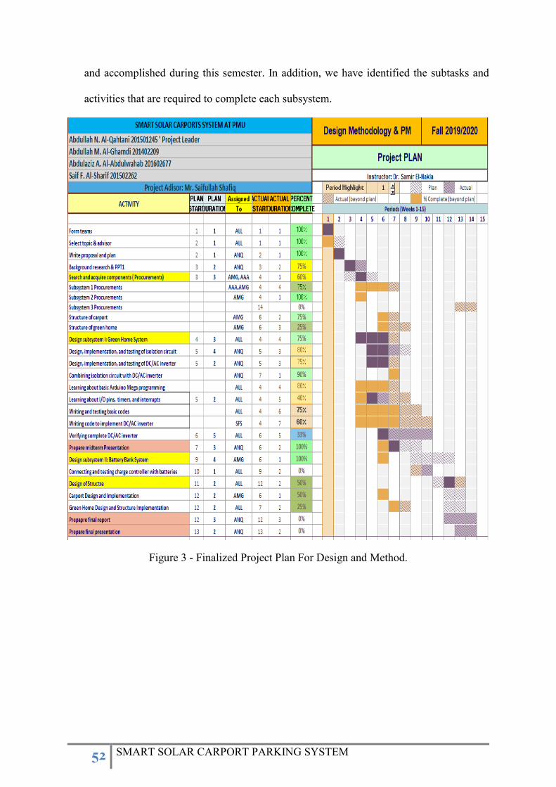
Figure 3 - Finalized Project Plan For Design and Method.
53 SMART SOLAR CARPORT PARKING SYSTEM
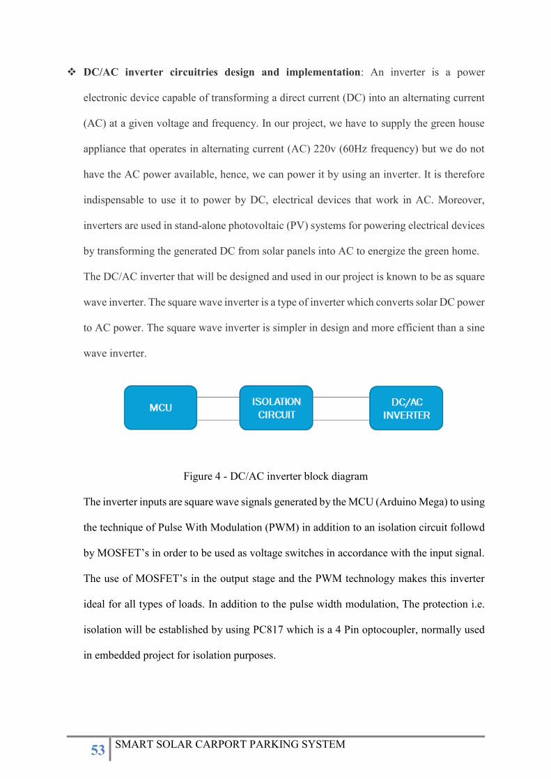
DC/AC inverter circuitries design and implementation: An inverter is a power
electronic device capable of transforming a direct current (DC) into an alternating current
(AC) at a given voltage and frequency. In our project, we have to supply the green house
appliance that operates in alternating current (AC) 220v (60Hz frequency) but we do not
have the AC power available, hence, we can power it by using an inverter. It is therefore
indispensable to use it to power by DC, electrical devices that work in AC. Moreover,
inverters are used in stand-alone photovoltaic (PV) systems for powering electrical devices
by transforming the generated DC from solar panels into AC to energize the green home.
The DC/AC inverter that will be designed and used in our project is known to be as square
wave inverter. The square wave inverter is a type of inverter which converts solar DC power
to AC power. The square wave inverter is simpler in design and more efficient than a sine
wave inverter.
Figure 4 - DC/AC inverter block diagram
The inverter inputs are square wave signals generated by the MCU (Arduino Mega) to using
the technique of Pulse With Modulation (PWM) in addition to an isolation circuit followd
by MOSFET’s in order to be used as voltage switches in accordance with the input signal.
The use of MOSFET’s in the output stage and the PWM technology makes this inverter
ideal for all types of loads. In addition to the pulse width modulation, The protection i.e.
isolation will be established by using PC817 which is a 4 Pin optocoupler, normally used
in embedded project for isolation purposes.
54 SMART SOLAR CARPORT PARKING SYSTEM
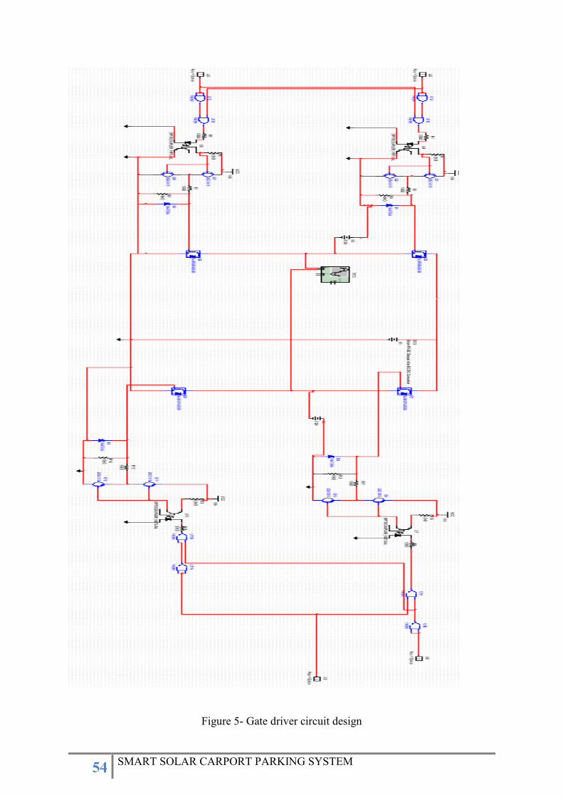
Figure 5- Gate driver circuit design
55 SMART SOLAR CARPORT PARKING SYSTEM
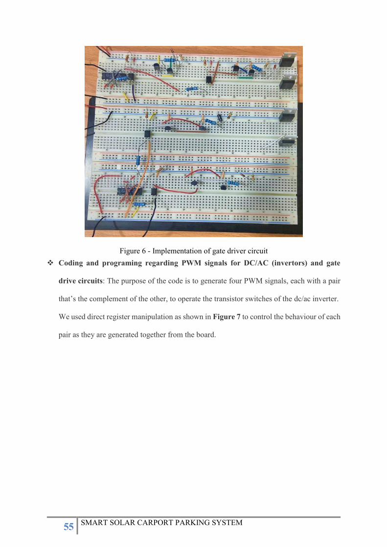
Figure 6 - Implementation of gate driver circuit
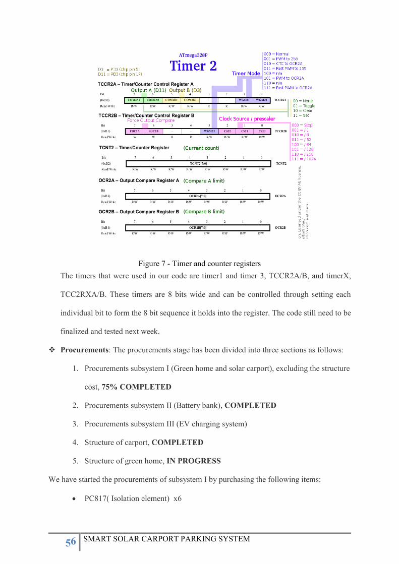
Coding and programing regarding PWM signals for DC/AC (invertors) and gate
drive circuits: The purpose of the code is to generate four PWM signals, each with a pair
that’s the complement of the other, to operate the transistor switches of the dc/ac inverter.
We used direct register manipulation as shown in Figure 7 to control the behaviour of each
pair as they are generated together from the board.
56 SMART SOLAR CARPORT PARKING SYSTEM
Figure 7 - Timer and counter registers
The timers that were used in our code are timer1 and timer 3, TCCR2A/B, and timerX,
TCC2RXA/B. These timers are 8 bits wide and can be controlled through setting each
individual bit to form the 8 bit sequence it holds into the register. The code still need to be
finalized and tested next week.
Procurements: The procurements stage has been divided into three sections as follows:
1. Procurements subsystem I (Green home and solar carport), excluding the structure
cost, 75% COMPLETED
2. Procurements subsystem II (Battery bank), COMPLETED
3. Procurements subsystem III (EV charging system)
4. Structure of carport, COMPLETED
5. Structure of green home, IN PROGRESS
We have started the procurements of subsystem I by purchasing the following items:
PC817( Isolation element) x6
57 SMART SOLAR CARPORT PARKING SYSTEM
7400 x4
A1015 (Transistor) x5
C1815 (Transistor) x5
Connectors 2 pins x10
Zener diode 15V/1W x5
IRF840 (MOSFET) x6
Resistors (6k, 2.2k, 10) Ω x6 of each
Arduino Mega x1
Circuit breadboard x5
Jumpers x1
Adapter 15V, 5A, 75W x3
IGBT H-bridge x1
Charge control unit x1
All the mentioned components above are electronic components in which they will be utilized
in subsystem I (Green home) in DC/AC invertor and its circuitries as explained earlier,
therefore, some components will be used in the solar panel and powering.
Structure design, solar panels and battery: We bought the solar panels, 3 x 160 W with
12V output and we were able to reduce the cost by 60 % by scaling down the capacity of
the solar panels (810 SAR vs 2000 SAR). We also bought one battery only instead of two
batteries to optimize the cost; the battery size is 12v, 150Ah with cost of 800 SAR.
Moreover, we have started the fabrication of the steel structure of the carport and battery
box with cost of 1200 SAR. Dimension of the carport structure is shown in below figure.
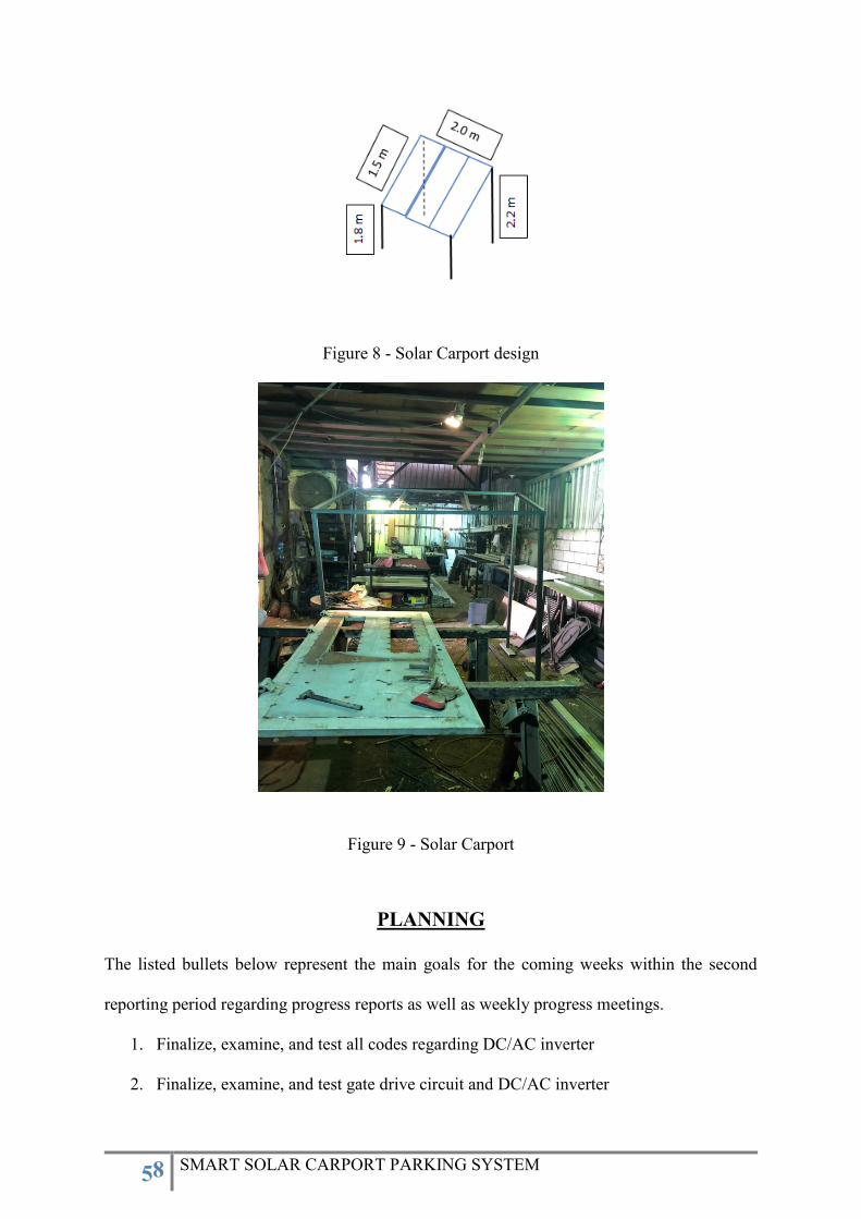
58 SMART SOLAR CARPORT PARKING SYSTEM
Figure 8 - Solar Carport design
Figure 9 - Solar Carport
PLANNING
The listed bullets below represent the main goals for the coming weeks within the second
reporting period regarding progress reports as well as weekly progress meetings.
1. Finalize, examine, and test all codes regarding DC/AC inverter
2. Finalize, examine, and test gate drive circuit and DC/AC inverter

59 SMART SOLAR CARPORT PARKING SYSTEM
3. Finalize, examine, and test gate sine-wave inverter
4. Start designing the green home structure, find workshops and vendors
5. Start Implementing solar carport
6. Start searching for components regarding EV charging system
60 SMART SOLAR CARPORT PARKING SYSTEM
Prince Mohammad Bin Fahd University (PMU)
Department of Electrical Engineering
Design Methodology & Project Management
Instructor: Dr. Samir El-Nakla
FALL 2019/2020
PROJECT PROGRESS REPORT II
SMART SOLAR CARPORT SYSTEM AT PMU
TEAM MEMBER:
Abdullah N. Al-Qahtani (Project Leader) 201501245
Abdullah M. Al-Ghamdi 201402209
Abdulaziz A. Al-Abdulwahab 201602677
Saif F. Al-Sharif 201502262
PROJECT ADVISOR
Mr. Saifullah Shafiq
Date November 4, 2019

61 SMART SOLAR CARPORT PARKING SYSTEM
This paper intended to provide a progress report and it briefly illustrates the performed tasks
regarding the project of smart solar carport system at Prince Mohammad Bin Fahd University
(PMU) October 14, 2019 – November 4, 2019
PERFORMED TASKS AND ACTIVITIES
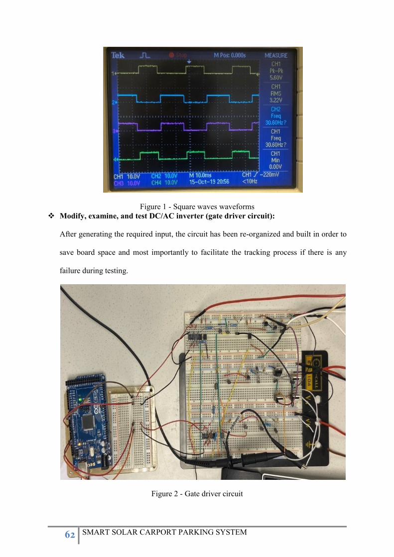
Modify, examine, and test code regarding DC/AC inverter (gate driver circuit):
In accordance with progress report I regarding gate driver circuit, the desired inputs are
four square waves. This can be established as it has been explained earlier by using the
method of timers manipulation, the chosen timers were timer 1 and timer 2.
void setup()
pinMode(10, OUTPUT);
pinMode(9, OUTPUT);
TCCR2A = B01010000;
TCCR2B = B01000011;
OCR2A = 127;
OCR2B = 156;
pinMode(11, OUTPUT);
pinMode(12, OUTPUT);
TCCR1A = (TCCR1A & 0b11111100) | 0b00000011;
TCCR1B = TCCR1B & B11111000 | B00000011;
OCR1A = 127;
OCR1B = 156;
void loop()
The code still going to be modified and tested with the gate driver circuit, the modification is
needed to increase the frequency from 30 Hz into 60 Hz as shown in Figure 1 to satisfy the
Saudi engineering standards and to be sufficient enough to handle and energize the available
appliances in the Saudi market.
62 SMART SOLAR CARPORT PARKING SYSTEM
Figure 1 - Square waves waveforms
Modify, examine, and test DC/AC inverter (gate driver circuit):
After generating the required input, the circuit has been re-organized and built in order to
save board space and most importantly to facilitate the tracking process if there is any
failure during testing.
Figure 2 - Gate driver circuit
63 SMART SOLAR CARPORT PARKING SYSTEM
The circuit has to be modified further by implementing a sine wave inverter to prevent
loads issues such as heat.
When the battery stores electricity in the DC form, green home loads or in general,
household electrical appliances use only AC current. The role of an inverter either square
wave or sin wave inverter is to convert the DC electricity stored in a battery into AC
electricity to be used by the house loads. An inverter, on the basis of its circuit, converts
the DC current to either sine wave AC current or square wave AC current. From a safety
perspective, the output of a sine wave inverter resembles AC current very closely when
compared to the square wave output, the sine wave output is quite pure. Most loads get
heated up when square wave inverter is used. Shortly, a square wave inverter is sufficient
to energize most loads and appliances but it is less safe for the appliances, whereas a sine
wave inverters are highly safe.
Prepare mid-term presentation using prezi:
The mid-term presentation has been designed and created through prezi website in which
it provides more presentation templates, animations, and features.
Please use the link below to present the presentation regarding smart solar carport system
at PMU
https://prezi.com/7urmcxlulbaq/?utm_campaign=share&utm_medium=copy
Green home structure: One of the main deliverables of the project is to provide and store
sufficient energy generated by solar panels mounted on carport in order to energize
residential appliances and charge electrical vehicles. Therefore, in accordance with the
submitted project plan, the green home scheduled to be completed by this semester beside
the carport structure and storage system. Hence, we have purchased the required materials
to start building and fabricating the green home structure, The structure will be built using

64 SMART SOLAR CARPORT PARKING SYSTEM
wood instead of steel to facilitate the fabrication and in-campus tasks such as building and
implementation.
Allocation of project location: The project location has been chosen with taking into
confederation several critical parameters that might affect the power production and the
efficiency of the solar panels such as; sunlight exposure, reflected shadow from buildings,
sunrise angle, and the project visibility.
Accordingly, the chosen location as shown below in Figure 3 has been proposed to the
department and the approval has been received in a timely manner, hence, the team with its
member would like to take the chance deliver its appreciation and thanks to, Acting chair
for the electrical engineering department Dr. Samir El-Nakla, Project advisor Mr. Saifullah
Shafiq, and all PMU staff for facilitating the request process
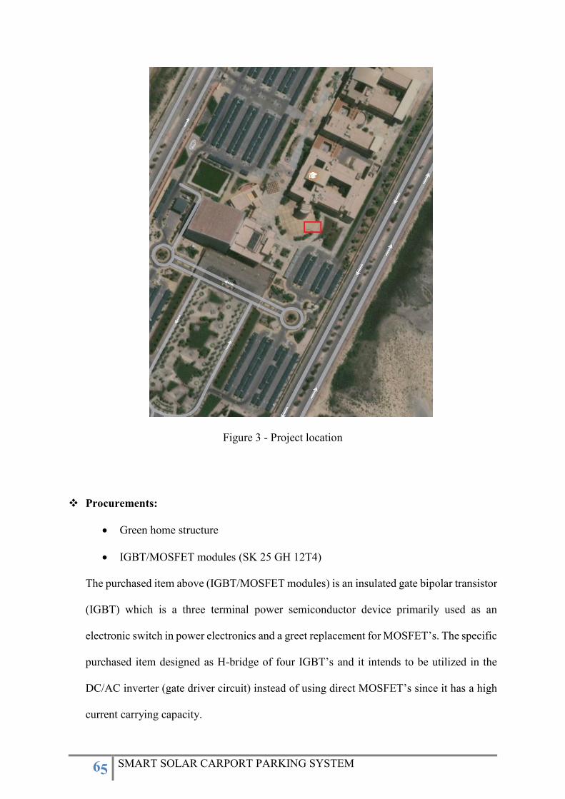
65 SMART SOLAR CARPORT PARKING SYSTEM
Figure 3 - Project location
Procurements:
Green home structure
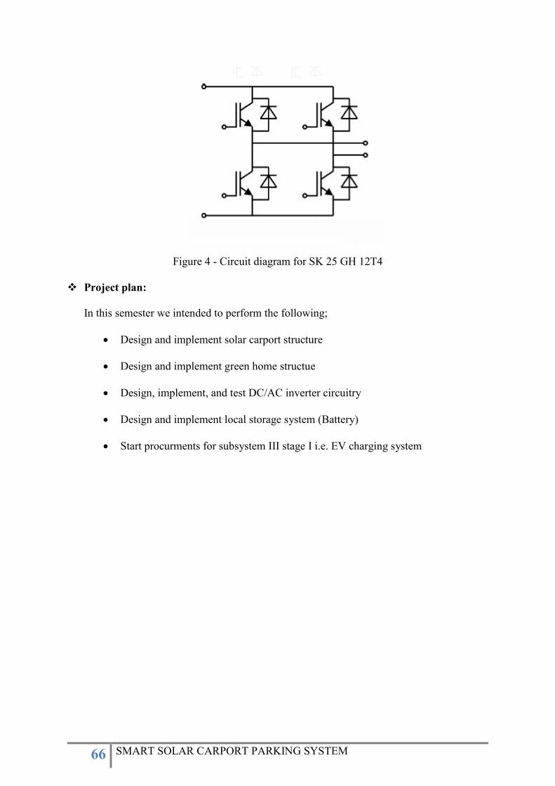
IGBT/MOSFET modules (SK 25 GH 12T4)
The purchased item above (IGBT/MOSFET modules) is an insulated gate bipolar transistor
(IGBT) which is a three terminal power semiconductor device primarily used as an
electronic switch in power electronics and a greet replacement for MOSFET’s. The specific
purchased item designed as H-bridge of four IGBT’s and it intends to be utilized in the
DC/AC inverter (gate driver circuit) instead of using direct MOSFET’s since it has a high
current carrying capacity.
66 SMART SOLAR CARPORT PARKING SYSTEM
Figure 4 - Circuit diagram for SK 25 GH 12T4
Project plan:
In this semester we intended to perform the following;
Design and implement solar carport structure
Design and implement green home structue
Design, implement, and test DC/AC inverter circuitry
Design and implement local storage system (Battery)
Start procurments for subsystem III stage I i.e. EV charging system
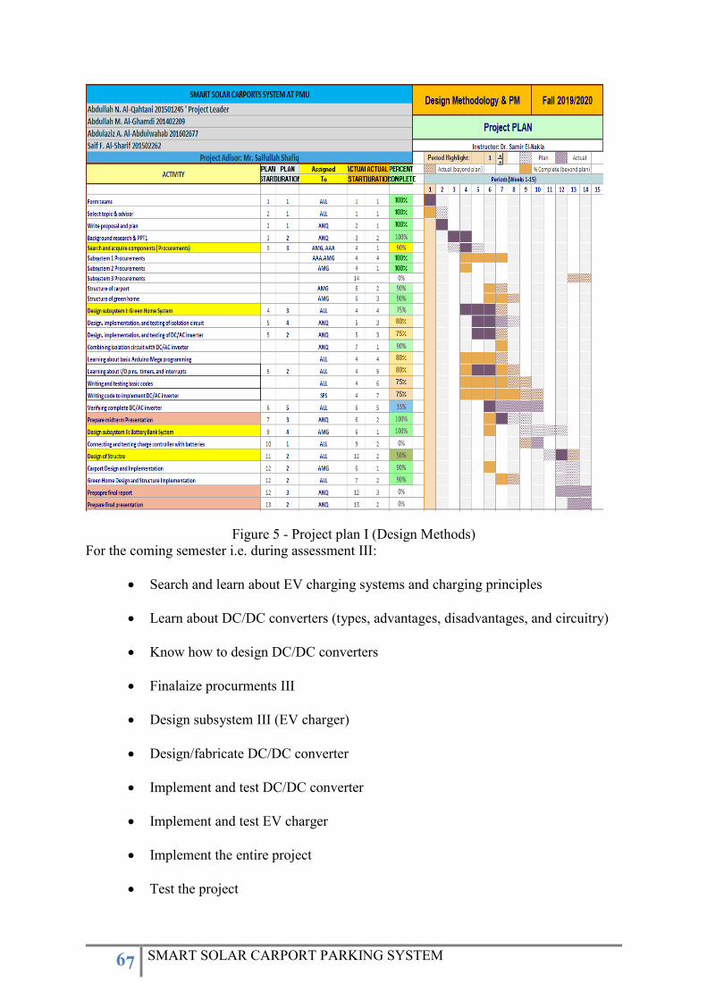
67 SMART SOLAR CARPORT PARKING SYSTEM
Figure 5 - Project plan I (Design Methods)
For the coming semester i.e. during assessment III:
Search and learn about EV charging systems and charging principles
Learn about DC/DC converters (types, advantages, disadvantages, and circuitry)
Know how to design DC/DC converters
Finalaize procurments III
Design subsystem III (EV charger)
Design/fabricate DC/DC converter
Implement and test DC/DC converter
Implement and test EV charger
Implement the entire project
Test the project
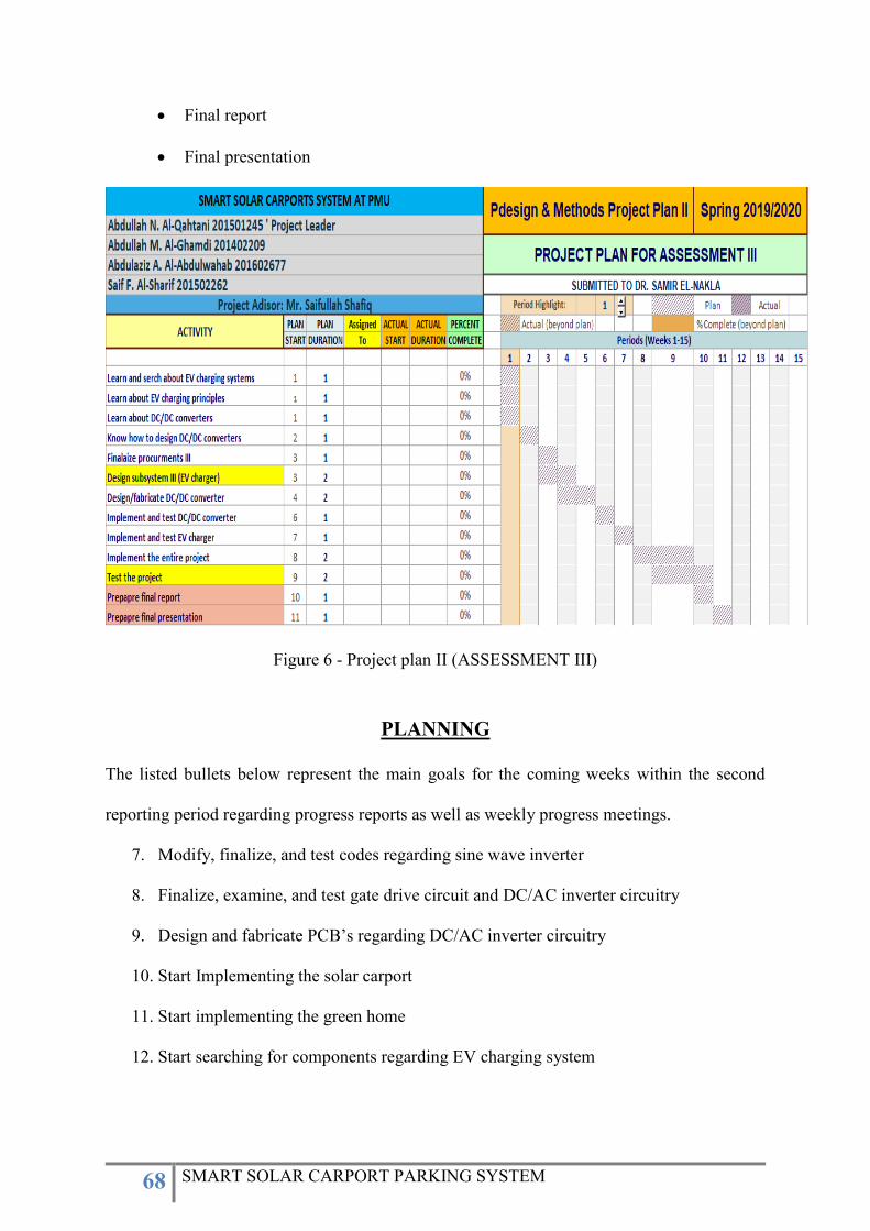
68 SMART SOLAR CARPORT PARKING SYSTEM
Final report
Final presentation
Figure 6 - Project plan II (ASSESSMENT III)
PLANNING
The listed bullets below represent the main goals for the coming weeks within the second
reporting period regarding progress reports as well as weekly progress meetings.
7. Modify, finalize, and test codes regarding sine wave inverter
8. Finalize, examine, and test gate drive circuit and DC/AC inverter circuitry
9. Design and fabricate PCB’s regarding DC/AC inverter circuitry
10. Start Implementing the solar carport
11. Start implementing the green home
12. Start searching for components regarding EV charging system
69 SMART SOLAR CARPORT PARKING SYSTEM
Prince Mohammad Bin Fahd University (PMU)
Department of Electrical Engineering
Design Methodology & Project Management
Instructor: Dr. Samir El-Nakla
FALL 2019/2020
PROJECT PROGRESS REPORT III
SMART SOLAR CARPORT SYSTEM AT PMU
TEAM MEMBER:
Abdullah N. Al-Qahtani (Project Leader) 201501245
Abdullah M. Al-Ghamdi 201402209
Abdulaziz A. Al-Abdulwahab 201602677
Saif F. Al-Sharif 201502262
PROJECT ADVISOR
Mr. Saifullah Shafiq
Date December 8, 2019
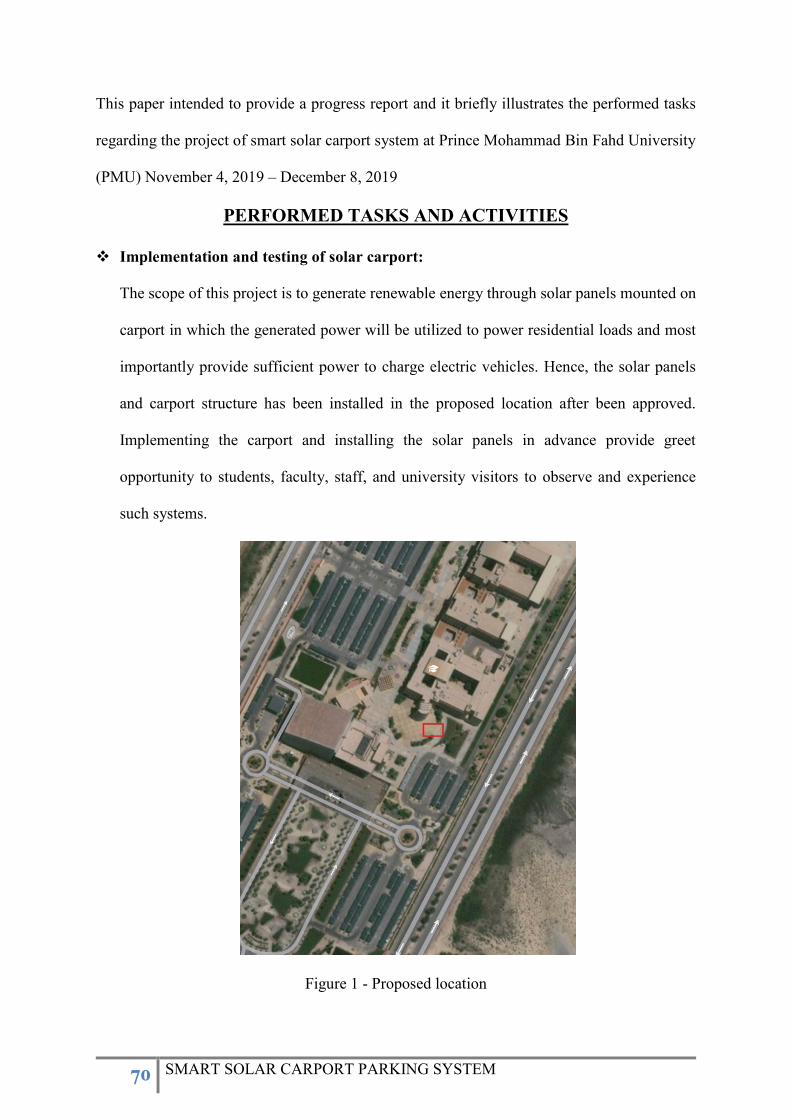
70 SMART SOLAR CARPORT PARKING SYSTEM
This paper intended to provide a progress report and it briefly illustrates the performed tasks
regarding the project of smart solar carport system at Prince Mohammad Bin Fahd University
(PMU) November 4, 2019 – December 8, 2019
PERFORMED TASKS AND ACTIVITIES
Implementation and testing of solar carport:
The scope of this project is to generate renewable energy through solar panels mounted on
carport in which the generated power will be utilized to power residential loads and most
importantly provide sufficient power to charge electric vehicles. Hence, the solar panels
and carport structure has been installed in the proposed location after been approved.
Implementing the carport and installing the solar panels in advance provide greet
opportunity to students, faculty, staff, and university visitors to observe and experience
such systems.
Figure 1 - Proposed location
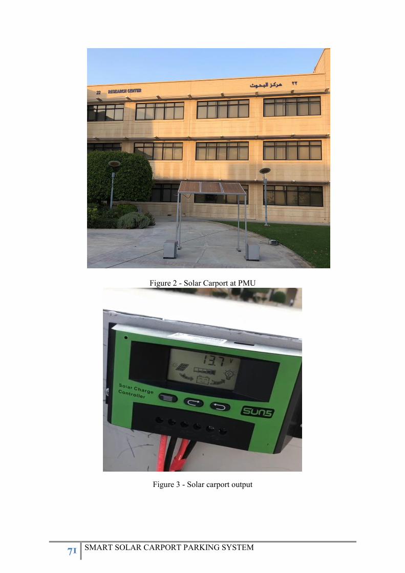
71 SMART SOLAR CARPORT PARKING SYSTEM
Figure 2 - Solar Carport at PMU
Figure 3 - Solar carport output

72 SMART SOLAR CARPORT PARKING SYSTEM
After the implementation, the charge controller installed and the designed carport
successfully generated solar energy with output voltage of 13.7 V as shown in Figure 3.
Furthermore, the team with its member would like to thank, Acting chair for electrical
engineering department Dr. Samir El-Nakla, Project advisor Mr. Saifullah Shafiq, and
PMU maintenance department with its staff for their support regarding the implementation.
Design and build a permanent DC/AC inverter (gate driver circuit):
Permanent circuit is an upgrade for the prototype version of any circuit and it provides
reliable circuitry. A typically permanent circuit board using universal board offers a simple
platform to arrange the electronic components in a compressed and efficient way based on
the design and how the designer desired to build it by soldering and offer varied advantages
which make them the perfect choice for projects since it lasts and live longer. The
advantages of enhancing our gate driver circuit to permanent soldered circuit are as follows:
1. Compact size and saving of wire: the interconnection between the components is
made through solder flux (iron) instead of wires and jumpers using the soldering
technique.
2. Immune to movement: since all components on the circuit board held fixed to the
board, it does not allow them to move irrespective of the movement of the board
itself.
3. Reliability: all the above factors bring reliability in the performance of the circuit.
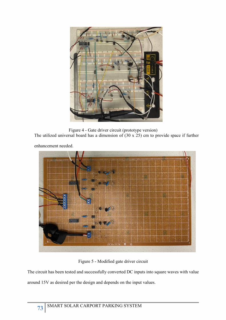
73 SMART SOLAR CARPORT PARKING SYSTEM
Figure 4 - Gate driver circuit (prototype version)
The utilized universal board has a dimension of (30 x 25) cm to provide space if further
enhancement needed.
Figure 5 - Modified gate driver circuit
The circuit has been tested and successfully converted DC inputs into square waves with value
around 15V as desired per the design and depends on the input values.
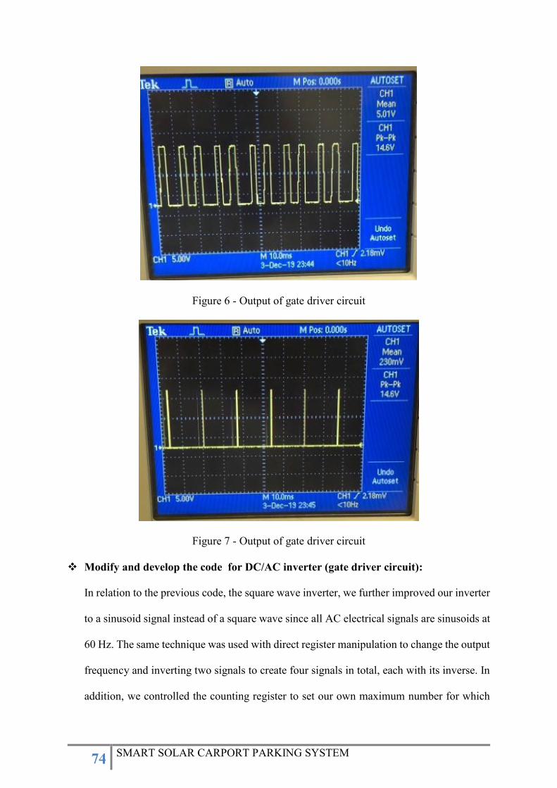
74 SMART SOLAR CARPORT PARKING SYSTEM
Figure 6 - Output of gate driver circuit
Figure 7 - Output of gate driver circuit
Modify and develop the code for DC/AC inverter (gate driver circuit):
In relation to the previous code, the square wave inverter, we further improved our inverter
to a sinusoid signal instead of a square wave since all AC electrical signals are sinusoids at
60 Hz. The same technique was used with direct register manipulation to change the output
frequency and inverting two signals to create four signals in total, each with its inverse. In
addition, we controlled the counting register to set our own maximum number for which
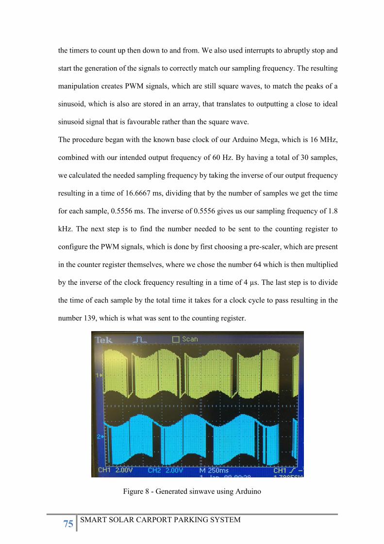
75 SMART SOLAR CARPORT PARKING SYSTEM
the timers to count up then down to and from. We also used interrupts to abruptly stop and
start the generation of the signals to correctly match our sampling frequency. The resulting
manipulation creates PWM signals, which are still square waves, to match the peaks of a
sinusoid, which is also are stored in an array, that translates to outputting a close to ideal
sinusoid signal that is favourable rather than the square wave.
The procedure began with the known base clock of our Arduino Mega, which is 16 MHz,
combined with our intended output frequency of 60 Hz. By having a total of 30 samples,
we calculated the needed sampling frequency by taking the inverse of our output frequency
resulting in a time of 16.6667 ms, dividing that by the number of samples we get the time
for each sample, 0.5556 ms. The inverse of 0.5556 gives us our sampling frequency of 1.8
kHz. The next step is to find the number needed to be sent to the counting register to
configure the PWM signals, which is done by first choosing a pre-scaler, which are present
in the counter register themselves, where we chose the number 64 which is then multiplied
by the inverse of the clock frequency resulting in a time of 4 µs. The last step is to divide
the time of each sample by the total time it takes for a clock cycle to pass resulting in the
number 139, which is what was sent to the counting register.
Figure 8 - Generated sinwave using Arduino
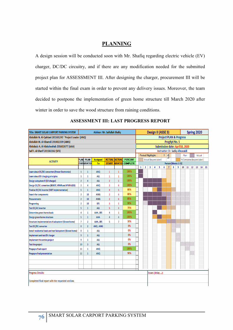
76 SMART SOLAR CARPORT PARKING SYSTEM
PLANNING
A design session will be conducted soon with Mr. Shafiq regarding electric vehicle (EV)
charger, DC/DC circuitry, and if there are any modification needed for the submitted
project plan for ASSESSMENT III. After designing the charger, procurement III will be
started within the final exam in order to prevent any delivery issues. Moreover, the team
decided to postpone the implementation of green home structure till March 2020 after
winter in order to save the wood structure from raining conditions.
ASSESSMENT III: LAST PROGRESS REPORT
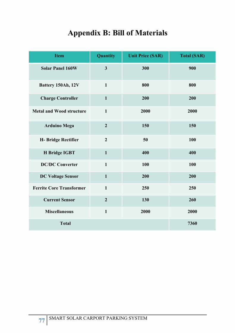
77 SMART SOLAR CARPORT PARKING SYSTEM
Appendix B: Bill of Materials
Item Quantity Unit Price (SAR) Total (SAR)
Solar Panel 160W 3 300 900
Battery 150Ah, 12V 1 800 800
Charge Controller 1 200 200
Metal and Wood structure 1 2000 2000
Arduino Mega 2 150 150
H- Bridge Rectifier 2 50 100
H Bridge IGBT 1 400 400
DC/DC Converter 1 100 100
DC Voltage Sensor 1 200 200
Ferrite Core Transformer 1 250 250
Current Sensor 2 130 260
Miscellaneous 1 2000 2000
Total 7360
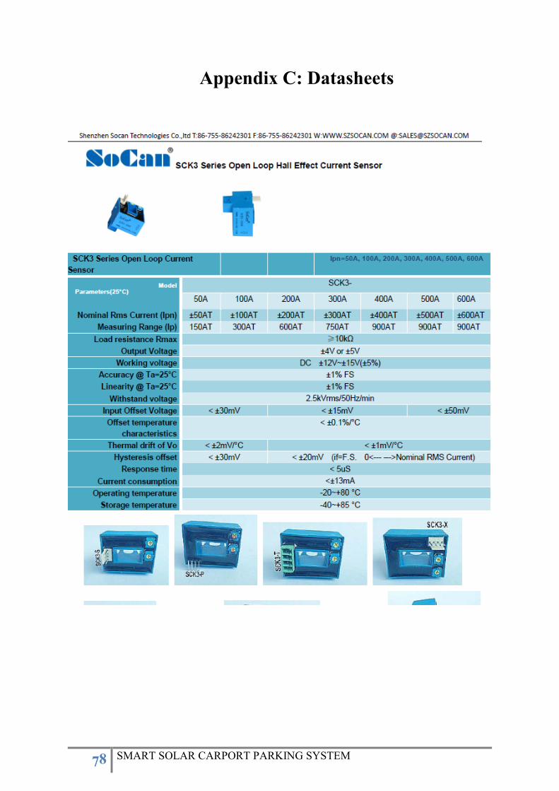
78 SMART SOLAR CARPORT PARKING SYSTEM
Appendix C: Datasheets
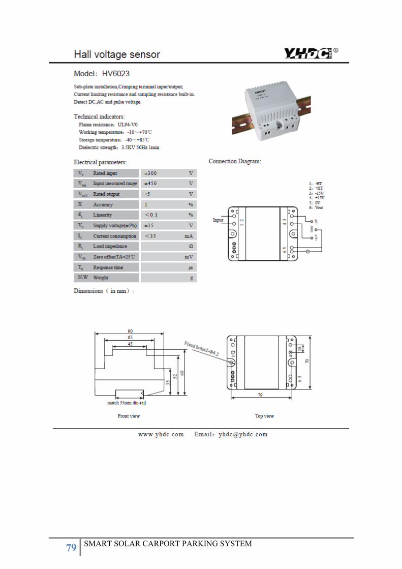
79 SMART SOLAR CARPORT PARKING SYSTEM

80 SMART SOLAR CARPORT PARKING SYSTEM
Appendix D: Program Codes
Arduino codes:
FOUR SIGNALS CODE #1:
void setup()
pinMode(9,OUTPUT);
pinMode(10,OUTPUT);
pinMode(11,OUTPUT);
pinMode(12,OUTPUT);
TCCR2A = 0b01010000;
TCCR2B = 0b01000011;
OCR2A = 127
OCR2B = 156
TCCR1A = (TCCR1A & 0b11111100) | 0B00000011;
TCCR1B = (TCCR1B & 0b11111100) | 0B00000011;
OCR1A = 127
OCR1B = 156
void loop()
~~~~~~~~~~~~~~~~~~~~~~~~~~~~~~~~~~~~~~~~~~~~~~~~~~~~~~~~~~~~~~~~

81 SMART SOLAR CARPORT PARKING SYSTEM
FOUR SIGNAL sPWM:
//int sinewave[] =
53,60,67,73,80,87,93,99,93,87,80,73,67,60,53,47,40,33,27,20,13,7,1,7,13,20,27,33,40,47;
int sinewave[] =
53,60,67,73,80,99,99,99,99,99,80,73,67,60,53,47,40,33,27,20,1,1,1,1,1,20,27,33,40,47;
//int sinewave[] = 0,25,50,75,100;
int i = 0;
double limit = 556;
void setup()
TCCR3A = 0;
TCCR3B = 0;
pinMode(5, OUTPUT); // on 3A Timer 3
pinMode(2, OUTPUT); // on 3B Timer 3
pinMode(6, OUTPUT); // on 4A Timer 4
pinMode(7, OUTPUT); // on 4B Timer 4
Serial.begin(9600);
bitSet(TIMSK3, TOIE3);
sei(); // enable all interrupts
ICR3 = limit;
OCR3A = (sinewave[i])*limit/100;
OCR3B = (sinewave[i])*limit/100;
/*-------------------------------------------------*/

82 SMART SOLAR CARPORT PARKING SYSTEM
/*-------------------- Timer 3 --------------------*/
TCCR3A = _BV(COM3A1) // Non-inverting PWM on OC3A
| _BV(COM3B0) // PWM on OC3B:
| _BV(COM3B1) // Inverting mode
| _BV(WGM31); // Phase correct PWM 16 bit
TCCR3B = _BV(CS31) | _BV(WGM33); // Prescalar = 8
/*-------------------------------------------------*/
ICR4 = limit;
OCR4A = (sinewave[i])*limit/100;
OCR4B = (sinewave[i])*limit/100;
/*-------------------- Timer 4 --------------------*/
TCCR4A = _BV(COM4A1) // Non-inverting PWM on OC3A
| _BV(COM4B0) // PWM on OC3B:
| _BV(COM4B1) // Inverting mode
| _BV(WGM41); // Phase correct PWM 16 bit
TCCR4B = _BV(CS41) | _BV(WGM43); // Prescalar = 8
/*-------------------------------------------------*/
/*-------------------------------------------------*/
void loop()

83 SMART SOLAR CARPORT PARKING SYSTEM
ISR(TIMER3_OVF_vect)
i = i + 1;
if(i == 30)
i = 0;
if(sinewave[i] == 0 || sinewave[i] == 100)
OCR3A = ((sinewave[i])*limit/100);
OCR3B = ((sinewave[i])*limit/100);
OCR4A = ((sinewave[i])*limit/100);
OCR4B = ((sinewave[i])*limit/100);
else
OCR3A = ((sinewave[i])*limit/100)-30;
OCR3B = ((sinewave[i])*limit/100)+30;
OCR4A = ((sinewave[i])*limit/100)-30;
OCR4B = ((sinewave[i])*limit/100)+30;