design and construction of aquaculture facilities in ... · chapter 1 introduction. principals in...
TRANSCRIPT

AD-A2;98 4bZ
D I CTechnical Report EL-93-1 1TI July 1993
US Army Corps I AUG2 6 1993of Engineers 6Waterways Experiment C DStation ,
Containment Area Aquaculture Program
Design and Construction of AquacultureFacilities in Dredged MaterialContainment Areas
by Jurij Homziak, C. David VealSea Grant Advisory Service
Donald HayesEnvironmental Laboratory
Approved For Public Release; Distribution Is Unlimited
93-19903
S2. 0 0 8 00liI llililhllPrepared for Headquarters, U.S. Army Corps of Engineers

The contents of this report are not to be used for advertising,publication, or promotional purposes. Citation of trade namesdoes not constitute an official endorsement or approval of the useof such commercial products.
4MSPRINTED ON RECYCLD PAPER

Containment Area Technical Report EL-93-11Aquaculture Program July 1993
Design and Construction of AquacultureFacilities in Dredged MaterialContainment Areasby Jurij Homziak, C. David Veal
Sea Grant Advisory ServiceMississippi Cooperative Extension ServiceMississippi State University Coastal Research and Extension Center2710 Beach Boulevard, Suite 1 EBiloxi, MS 39531
Donald Hayes
Environmental Laboratory
U.S. Army Corps of EngineersWaterways Experiment Station3909 Halls Ferry RoadVicksburg, MS 39180-6199
MC QUALITY INSPECTS 3Accesion• For
NTIS CRA8&I
Final report DTIC TAB
Approved for public release; distribution is unlimited U:1armo•vicea
ByDistribution I
Availability Codes
Avail andlorDist Special
Prepared for U.S. Army Corps of EngineersWashington, DC 20314-1000

US Army Corpsof EngineersWaterways Experiment N
WA'•EWAAL IDI M•S"'a
AIEA OF AAR. •11ir
Waterways Experiment Station Cataloging-in-Publication Data
Homziak, Jurij.Design and construction of aquaculture facilities in dredged material
containment areas I by Junj Homziak, C. David Veal, Donald Hayes ; pre-pared for U.S. Army Corps of Engineers.
116 p. :ill. ; 28 cm. -- (Technical report ; EL-93-1 1)Includes bibliographical references.1. Fish ponds. 2. Dredging spoil -- Environmental aspects. 3. Fish-
culture. 4. Shellfish culture. I. Veal, C. David. II. Hayes, Donald FIll. United States. Army. Corps of Engineers. IV. U.S. Army EngineerWaterways Experiment Station. V. Containment Area Aquaculture Pro-gram. VI. Title. VII. Series: Technical report (U.S. Army Engineer Wi-terways Experiment Station) ; EL-93-1 1.TA7 W34 no.EL-93-1 1
PHNE (M04

Contents
Preface ........................................... vi
Conversion Factors, Non-SI to SI Units of Measurement ........ .viii
1-Introduction ...................................... 1
2-Facility Design and Construction ........................ 3
Preparation of Plans ................................ 3Project objectives ..... ........................... 3Planning outline .................................. 4Identification of project ............................. 4Feasibility of outline plan ........................... 5
Topography .................................. 7Cross and longitudinal sections ...................... 7Soils ........................................ 8Water ....................................... 10
Detailed plan ................................... 11Site Layout ...................................... 14Designs ........................................ 15
Production calculations ............................ 15Drawings ...................................... 16
Cost and Quantity Estimates .......................... 17Detailed estimates ................................ 18Quantity estimates ................................ 19Organization and supervision ........................ 19
Pond Design Criteria .............................. 19Pond configuration ............................... 19Pond size ...................................... 20Dikes ........................................ 21Pond inlets/outlets ............................... 26Harvest basins .................................. 30Water-distribution and drainage canals ............... .. 30
Water bupply .................................... 32Hydraulic computations ............................ 33Quantity estimates ............................... 34Pumps ........................................ 36
iii

Water quality ................................... 38Water sources ................................... 39Pretreatment ................................... 41Filters ....................................... 43Pond effluent ................................... 46
Construction of Commercial Facilities: Examples ......... .. 47Catfish ....................................... 47Crawfish ...................................... 48Other freshwater fish .............................. 48Bait fish ...................................... 48Marine/brackish water fish .......................... 50Shrimp ....................................... 51Freshwater shrimp ............................... 51Mollusks ...................................... 51Fee fishing ..................................... 52Extensive culture ................................ 52
3-DMCA Design and Operations ......................... 53
Introduction ..................................... 53Design Considerations .............................. 53
Dredging operations .............................. 54Effluent quality ................................. 54Storage capacity ................................. 55Structural elements ............................... 55
DMCA Operations and Management .................... 56Predredging management ........................... 56Management during disposal ........................ 57Postdisposal management .......................... 57
4-Design and Construction of the CAAP Demonstration Facility,Brownsville ........................................ 58
Introduction ..................................... 58Brownsville Demonstration Project ..................... 58
Identification of project ............................ 58Production plan ................................. 59Feasibility plan ................................. 60Project location ................................. 60
Site Characteristics and Influence on Facility Design ....... .. 61Hydrology ..................................... 61Climate ....................................... 61Topography and soils ............................. 62
Facility Construction ............................... 64Site survey ..................................... 64Site layout ..................................... 64Intake caral ..................................... 65Pond dikes and interiors ........................... 65
iv
" • ' l l I I I li I IM imi

Buildings and machinery ........................... 66
Water-distribution and control structures ................ 67
References ......................................... 71
Figures 1-31
SF 298
List of Tables
Table 1. Soil Groups Suitable for Dike Construction, Permeability,and Stability Rating of Earthen Dikes (from KOvari(1984b)) .................................. 9
Table 2. Recommended Minimum Dam Top Widths (from Soil
Conservation Service (1969)) ................... 23
Table 3. Fill and Drain Times for Warmwater Fish Culture ..... 27
Table 4. Water Quality Screening Criteria and Allowable ProductionLevels for Marine Aquaculture (from Huguenin and Colt(1989)) .............................. 39
Table 5. Bottom Grades for Fish Ponds .................. 50
V

Preface
The report herein describes research performed under the National Oce-anic and Atmospheric Administration (NOAA) Grant No. NA89AA-D-SG016. The work was conducted under the Containment AreaAquaculture Program (CAAP) sponsored by the Headquarters, U.S. ArmyCorps of Engineers (HQUSACE), and monitored by the U.S. Army Engi-neer Waterways Experiment Station (WES).
The Principal Investigators and authors of the report were Drs. JurijHomziak anod C. David Veal, Mississippi State University Coastal Re-search and Extension Center (CREC) and Mississippi Sea Grant AdvisoryService (MSGAS), and Mr. Donald Hayes, WES. Dr. Homziak is a Ma-rine Resources Specialist with CREC and an Aquaculture Specialist withMSGAS. Dr. Veal is Head of CREC and Leader, MSGAS.
The authors would like to express their appreciation for the assistanceand guidance of Mr. Richard Coleman, Program Manager for the CAAP,Mr. Dave Nelson, Principal Investigator for the CAAP, and to members ofthe Field Review Committee, particularly Mr. Braxton Kyzer, CharlestonDistrict, Messrs. Rick Medina and Herbie Maurer, Galveston District, andMr. Pat Langen, Mobile District. Dr. Mark Konikoff, University of South-west Louisiana, provided valuable contributions to numerous planning anddesign activities. Special appreciation is due to Mr. Durwood Dugger,Cultured Seafood Group, who was onsite manager of the demonstrationfarm. Much of the facility design was a product of Mr. Dugger's insight.Messrs. Art Barrera and Abel Guerrero, Brownsville Area Office, Galves-ton District, also contributed significantly to the success of the project.Mr. Arthur Bennett, Vicksburg District, designed the concrete structures.Mr. Randy Crist, WES, was responsible for overseeing the preparation ofall figures and drawings used in the project. The project benefitted fromthe critical oversight of Mr. Jesse Pfeiffer, Directorate of Research and De-velopment, HQUSACE.
Contract Manager for this study was Mr. Richard Coleman, CAAP Proj-ect Manager. The study was conducted under the direct supervision ofMr. E. J. Pullen, Chief of the Coastal Ecology Branch, Ecological Re-search Division (ERD), Environmental laboratory (EL), WES, and underthe general supervision of Dr. C. J. Kirby, Chief, ERD, and Dr. John Harri-son, Director, EL.
vi

At the time of publication of this report, Director of WES was Dr. Rob-ert W. Whalin. Commander was COL Leonard G. Hassell, EN.
This report should be cited as follows:
Homziak, J., Veal, C. D., and Hayes, D. (1993). "Designand construction of aquaculture facilities in dredged materialcontainment areas," Technical Report EL-93- 11, U.S. ArmyEngineer Waterways Experiment Station, Vicksburg, MS.
vii

Conversion Factors,Non-SI to SI Units of Measurement
Non-SI units of measurement used in this report can be converted to SIunits as follows:
Multiply By To Obtain
acres 4,046.873 square meters
feet 0.3048 meters
horsepower (550 foot-pounds 745.6999 watts(force) per second)
inches 2.54 centimeters
metric tons 1000.0 Idlograms
tons (2,000 pounds, mass) 907.1847 kilograms
viii

1 Introduction
The culture of fish and shellfish usually involves some type of struc-ture to contain the cultured species. Pond-based production systems arethe most common and are the central components of fish and shellfish(crawfish, shrimp, and mollusks) farms. ' he two main types of ponds areexcavated ponds and diked ponds. This report will focus on the dikepond, formed by building an aboveground structure (dike or levee) to im-pound water. The design of aquaculture ponds varies according to speciescultured, management effort, and any special use (nursery or holdingpond) the pond may have. Because of this variability, a general approachto design and construction will be followed. Significant variations in de-sign or construction requirements will be presented as well.
The success of any production system in industry and agriculture reliesheavily on design and construction. A well-designed and constructed sys-tem provides the foundation for successful operations. Even the best man-agement techniques can do little to optimize production in poorlydesigned and inadequately constructed systems. This applies to ponds atall levels of management.
While the specific objectives of individual pond production systemscan vary widely, they all depend on the same biological and technicalbase. However, neither a good understanding of biology or engineeringalone is likely to result in a practical system. Success depends on a blendof expertise in these and other disciplines. Avoidable mistakes in pond de-sign and construction are not uncommon.
It is not uncommon for major decisions to have been made and fixedprior to seeking engineering assistance. This can be a serious problemthat may threaten project viability or add considerable cost to the opera-tion. It is strongly advised to consult with professionals in the site selec-tion, design, and construction phases of the planned operation. Whereaquaculture is well established, such as in the catfish-producing region ofthe Deep South or the crawfish region of Louisiana, both public (Exten-sion Service, Soil Conservation Service, and University) and private sec-tor expertise in these critical areas is available. Where aquaculture is anovel industry, it is wise to seek out assistance and is crucial for
Chapter 1 Introduction

principals in the operation to be familiar with the basic principals of siteselection, pond design, and construction.
This report is intended to provide an overview of the considerableknowledge and experience that has ben developed worldwide in the de-sign, construction, and operations planning of pond-based aquaculture sys-tems. Because 0-iis is a complex subject and requirements for specificsituations are hkg'i'y variable, only generalized, conservative views willbe presentid. The review is not intended for experts or those experiencedin aquaculture pnd design and construction. It is intended primarily asan information resource for those involved in aquaculture development.
Mu,.h information on aquaculture engineering is difficult to locate, itis scattered through the literature, frequently in publications not generallyavailable to the nonprofessional. While this report provides an overviewof pond design and construction, certain references are worthwhile search-ing out for their added information. In no special order of importance,Mayo (1988), Wheaton (1977), Food and Agriculture Organization/UnitedNations Development Program (FAO/UNDP) (1984), Murray, Wong, andPruder (1986), and Huguenin and Colt (1989) are among the better re-views of aquaculture engineering. Reviews of culture methods for particu-lar species also provide excellent coverage of specific design andconstruction problems. Chieu, Santos, and Juliano (1988), Dupree andHuner (1984), Lee (1981), Tang (1979), and Ulmer (1987, 1990) are goodexamples. The Soil Conservation Service also provides information frombasic (e.g., 1971a, 1982a) to complex (e.g., 1969, 1971b) on pond plan-ning, design, and construction.
2 Chapter 1 Introduction
2 Facility Design andConstruction
Preparation of Plans
The following description of the planning process is adapted fromK6vari (1984a) and Huguenin and Colt (1989).
Project objectives
Project preparation usually includes all of the activities short of the de-cision to implement the project. A critical first design step is the defini-tion of project objectives. While objectives may at first be broadly stated,they must be quantified and specified in detail before any design calcula-tions can be done. Because both present and future project needs must beconsidered, all explicit and implied assumptions included in the project ob-jectives must be clearly identified. Use of a dredged material containmentarea (DMCA) incorporates multiple goals. It is important to order priori-ties and resolve conflicts to arrive at design decisions.
Project objectives and physical data for the selected site are related indesigning the aquaculture facility. Design is a complex and iterative pro-cess. Decisions (including future plans) regarding species to be cultured,site characteristics, farm size, water sources and anticipated demands,stocking densities, production cycles, management options, access andutilities provisions, equipment and supply needs and maintenance, reliabil-ity and replacement schedules, and others must be made early and in de-tail. As these project decisions are combined with information developedduring the planning process, broad objectives will be refined into increas-ingly detailed statements that are successively incorporated into the plan.The apparent redundancy in the planning process outlined below simply re-flects the iterative and progressively complex nature of the decision-making process.
Chapter 2 Facility Design and Construction 3

Planning outline
Project preparation and planning should include the following steps:
a. Identification of the project; an outline defining species cultured,culture system, and production target.
b. Feasibility plan.
c. Detailed production plan.
d. Preparation of cost estimates.
e. Preparation of contractual documents.
Identification of project
The first steps in project planning are the definition of the project, iden-tification of project objectives, and a broad concept of the design of theproduction facilities. This is an integral part of the site selection and eval-uation process for any project. Figure 1 (adapted from Huguenin and Colt(1989)) is a simplified schematic of the process. It is important that theaquaculture users and design engineers for both disposal and aquaculturefunctions cooperate in defining the production system, quantifying objec-tives and evaluating potential solutions. Cooperation, interaction, andfeedback are especially important in designing multiple-use DMCA be-cause of the wide divergence of project objectives between aquacultureand dredged material disposal.
Decisions regarding project objectives are incorporated first into thefeasibility plan and finalized in the production plan. While the subjectivenature of these plans should be recognized, they are needed to progres-sively guide facility design. Both feasibility and production plans arebased on the number of steps in the production cycle, the amount of timerequired, and survival in each step. This information is used to calculatevalues for all of the major variables (e.g., water volumes, inflow and out-flow, feed and other inputs, production level and timing, and labor) em-ployed in the planned production process. Other factors, includingenvironmental conditions, technical variables and skills of personnel, andothers, will affect these estimates. Because all of these variables are inter-dependent, tradeoffs will be necessary between production goals andwater quality, stocking densities, operational procedures, feed require-ments, equipment needs, economics, and levels of acceptable risk.
Chapter 2 Facility Design and Construction

Feasibility of outline plan
The purpose of the feasibility plan is twofold. The first function is toconfirm that the project can be developed at the selected site. The secondis to collect and provide all data, calculations, and plans needed for proj-ect approval and detailed planning.
The following data and maps should be available for the selected site.
a. Maps.
(1) Contour maps (1:25,000 to 1:50,000).
(2) Map showing legal ownership.
f3) Soil or geological map.
(4) Water resources map, including surface water sources, drywater courses, wells, water tables, and aquifer watercharacteristics and yield estimates.
(5) Climatological map showing nearest meteorological stationsand mean monthly values of temperature and rainfall.
b. Meteorological data, mean monthly rainfall, evaporation humidity,wind speed and direction, and sunlight (solar radiant flux).
c. Hydrological data.
(1) Discharge, yield flood and water elevations for existing watersources, including any data on restrictions or competing uses.
(2) Tidal data for marine/brackish water sites.
The feasibility or outline plan is usually the basis for permit applica-tions and for securing external financing for the project. The plan shouldillustrate the technical feasibility of the project. Production calculationsand design should be presented in sufficient detail to allow for reliablecost estimates to be made.
The main parts of the feasibility plan are as ftollows:
a. Report.
(1) Contains the most important information on the project,including a site description, soil characteristics (determinedduring the survey and assessment phase), water sources andresults of water analysis, pond discharge estimates, andmeteorological data used in planning.
Chapter 2 Facility Design and Construction

(2) Provides the proposed operations plan with productioncalculations, planning considerations, site layout (with roads,buildings, and other facilities), arrangements of the watersupply, and drainage.
(3) Includes an abstract of costs of capital, operational andproduction costs, analysis of benefits, and the proposedconstruction program.
(4) Includes a list of legal documents acquired or applied for toallow the project to proceed.
b. Maps and plans, including the following:
(1) General location map (unscaled).
(2) Site map (scale 1:2000 to 1:5000, depending on project size),showing boundary lines, project site, existing features, contourlines, water source and drainage locations, and the locations ofsoil test pits.
(3) Layout map (scale 1:1000 to 1:5000), showing arrangement ofponds, water supply and drainage systems, locations ofbuildings and other works, and proposed approach roads andutility lines.
c. List of all proposed buildings and their plinth areas and a list ofequipment needed for the project.
d. Soil and water test results for engineering and productioncalculations in tabular form.
e. Typical outline cross sections of dikes and channels, showing slopesand dimensions.
f. Cost estimates for civil works, showing major quantities and unitrates for each item (buildings, structures, earthwork, utility supply,engineering, equipment, and physical contingencies). Estimates ofoperational costs and production costs should also be provided.
g. A project schedule based on project characteristics and quantitycalculations, showing the time required for the activities required tocomplete the detailed plans.
Topography and soils and water data, combined with the productionplan, form the basis on which all of the remaining site plans are based.Accurate collection, analysis, and interpretation of these sample data arecritically important. The main points are reviewed in the followingsection.
6 Chapter 2 Facility Design and Construction

Topography. Two types of ponds will be encountered most frequentlyin containment area aquaculture, the diked pond and a variant, the cut-and-fill pond. Diked ponds are formed by building a dike or levee to impoundwater. These are commonly used for fish culture because they may bebuilt in a range of topographic conditions. Most DMCA aquacultureponds will be of this type. In cut-and-fill type ponds, material for embank-ments is cut from the pond bottom and shaped into perimeter dikes.Diked ponds require relatively flat terrain and are common in the maincatfish-producing regions of the United States.
Site topography is of great importance in pond construction. The de-sign, orientation and elevation of ponds, water-distribution canals, and har-vest structures depend on site topography. Although embankment typeponds can be constructed on a wide variety of topographic surfaces, landsurfaces with a moderate slope in one or two directions are preferred.Areas with low slope, I to 5 percent, are suitable for pond construction,but slopes of 2 percent or less preferred. Moderate slopes simplify deliv-ery of water and gravity drainage of ponds. Topography around pondsshould allow gravity drainage of the pond in any season. Water heights inexternal ditches and adjacent water bodies should be lower than the ponddrain, even under expected high water conditions.
Site surveys should be done by a professional survey staff or in cooper-ation with the local Soil Conservation Service office. The survey shouldconfirm the project boundaries and establish reference points for levelingoperations and for the location of site facilities. It should also show allfeatures and structures that exist onsite. Topographic surveys at scales of1:500 to 1:5000 and with contour lines of 20 to 30 cm (about 1 ft) verticalspacing (10 cm for flat land) are appropriate for site planning and designof project facilities. This scale is needed to design pond fill and drainagesystems, bottom slopes, and estimate earthwork volumes with the requiredaccuracy.
Cross and longitudinal sections. Cross and longitudinal sections ofany existing earth structures (embankments and canals) should be taken at50- to 100-m spacing. Cross sections should have a scale of 1:100.Points should be spaced to permit plotting of the actual terrain with± 20-cm accuracy on cross sections of 1:100. Cross sections should alsobe plotted at the sites of any major structures, particularly existing weirs.Cross sections should be individually marked and numbered. For intakeand discharge canals leading to the site, continuous profiles and cross sec-tions at 500-m intervals or less are needed. Cross sections should includeall dimensions needed for marking out as well as actual height. All eleva-tions (dike tops, bottoms of canals and basins, etc.) must be indicated inall cross sections. Wave protection cross sections should be prepared on ascale of 1:50.
Longitudinal sections should be plotted on a scale of 1:100 vertical and1:500 to 1:5000 horizontal. That should contain length, bottom level inponds or drains, the location of the structures, ground level, and
Chapter 2 Facility Design and Construction 7
designated crest level of dikes. Longitudinal sections are particularly im-portant in designing water supply channels in larger ponds. Sectionsshould be provided for the main and secondary water distribution chan-nels, the drainage canals, any internal pond drains, and the dikes. Longitu-dinal sections with associated cross sections can be used to calculatequantities associated with different earthworks.
Soils. Soil type is as important as topography in site selection. Sur-face and subsurface soil information is essential for engineering purposes.These data should be collected as early as possible in the initial site evalu-ation and selection process. Existing guidelines (U.S. Department of theInterior 1965) for collecting soil data should be followed.
Sufficient borings and samples should be collected to determine thatconditions are appropriate for pond construction. One or two sample sta-tions for each 2 to 5 ha of site area are appropriate for homogenous soilconditions. More stations will be needed under variable soil conditions.Advice on the appropriate number of samples for variable soils should besought from the Soil Conservation Service or from a professional engi-neer. The depth of the bore hole should be a minimum of 2.0 m below thedeepest intended excavation in the project area. The depth and number ofsamples for special structures should be determined by professionalengineers.
Geotechnical data should identify soil stratification throughout thepond area, under the dikes, along the routes of any canals, and at the siteof any proposed structures. At a minimum, the data should be sufficientto estimate seepage losses (bottom and dike), foundation conditions fordikes and structures, risk of seepage and piping, degree of compaction, al-lowable flow velocities in canals and intake basins, and erosion potential.
In addition to soils information, the data should include information onchemical contaminants at the site and the characteristics of the groundwa-ter tables at the site. Subsurface water may become an engineering prob-lem once a site is used for material disposal. Inadequate dewatering maycreate unstable pond bottoms.
Sandy clays to clay loam soils are best for both pond construction andfertility. In general, aquaculture ponds will be sited in areas where thesoils below the proposed pond bottom have a grain size curve plotted tothe left of the grain size curve A in Figure 2. The coefficient of permeabil-ity should be less than 5 x 10⁻⁶ m/sec. Dikes without impervious claycores are generally built from soils with grain size curves plotted betweencurves A and B in Figure 2, with coefficients of permeability between5 x 10.6 and 1 x 10⁻⁴ m/sec. If clay is to be used to create an imperviousdike core, it should have a liquid limit <80 percent, a plastic limit <20 per-cent, and a plasticity index >30 percent (Kovari 1984b; Szilvassy 1984).
8 Chapter 2 Facility Design and Construction

Using boundary classifications, the soil groups in Table I are suitablefor dike construction. These data should be available for the project sitefrom the cooperating Corps of Engineers District.
Table 1Soil Groups Suitable for Dike Construction, Permeability, andStability Rating of Earthen Dikes (from K6vari (1984b))
Soil Group Stability of Dike Psrmeebllity, cm/sec
GM Reasonably stable; may be used for impervious cores or 10.3 to 10"6blankets
GC Fairly stable; may be used for impervious cores 10-6 to 10-8
SM Fairly stable; may be used for impervious cores or dikes 10-3 to 10-6
SC Fairly stable; use for impervious cores 106 to10-8
ML, MI Poor stability; may be used for dikes with proper conltro 10-3 to 10-6
CL, CI Stable; impervious cores and blankets 10- to 10"
CH Fair stability with fiat slopes; used for cores, blankets, and 10"- to 10dike sections
Other soil characteristics exist that may be important in site design.One, the critical void ratio, has been introduced as an index of volume sta-bility for aquaculture pond construction worldwide (FAOIUNDP 1984).Szilvassy (1984) reviews the procedures for estimating this value and pro-vides guidelines for the use of this index. The Proctor density is a morefrequently encountered measure of compaction in the United States.
An important consideration in designing aquaculture ponds is that thelow earth dikes do not warrant expensive tests in soils laboratories. De-sign values of soil strength are costly to determine and require experi-enced judgement to interpret. Soil properties for dike construction atDMCA sites will have been evaluated by qualified engineers. Site soiland subsoil characteristics that are adequate for the construction of con-tainment dikes will also suffice for dikes modified for aquaculture. Sitesoils data will be available at the Corps of Engineers District involved inthe dredging project. These should be reviewed by a qualified aquacultureengineer or a specialist from the Soil Conservation Service and incorpo-rated into designs for pond and dike construction.
The soils report should include the final version of the maps providedin the feasibility plan. Pertinent physical data from both the DMCA andaquaculture site evaluations should be presented. Any missing site orsoils data must be collected and included at this point. Kdvari (i 984a)proposes a comprehensive report format.
Chapter 2 Facility Design and Construction 9

The report should contain the sample sites, methods, and results of insitu and laboratory tests. Information on allowable bearing capacity andsettlement, quantity of soluble salts, water table characteristics, and con-siderations affecting dike, foundation, and canal construction should be de-scribed in detail. Specific laboratory test results should be included in thesoils report. The report or the results should include the followingcomponents:
a. Soil consistency, including liquid limit (LL), plastic limit (PL),plastic index (PI), and relative consistency (Cr).
b. Soil components, including grain-size analysis curves, coefficients ofuniformity (Cu), and particle-size analysis.
c. Index properties, such as water content (w), void ratio (e), porosity(n), dry density (yd), wet density (ywet), proctor maximum drydensity (yPr), absolute specific gravity (Gas), apparent specificgravity (Gs), cohesion (c), angle of internal friction (ý), allowablebearing capacity (oa), modulus of elasticity (E), and permeabilitycoefficient (k).
d. Location map, showing all sample locations with ground elevations.
e. Logs of sample stations. A record of the data concerning soils andconditions encountered at all sample stations and the results oflaboratory tests by sample. Because most of the subsequentconclusions and calculations will be based upon these data, the logmust be factual, accurate, clear, and complete.
f. Soil profiles. Sections to show subsurface conditions andstratification.
Water. Planning an aquaculture system requires that adequate water beavailable for both initial and future needs. Future needs include anyplanned expansion of the facility and changes in species cultured or man-agement intensity. In all cases, an excess is preferred to a shortage.Changes in water quality or quantity because of projected developmentshould be considered.
Information on water supply and quality should be available from theinitial site survey. If surface water is to be used in filling the pond, thewater quality of the intake water at the times that ponds are filled shouldbe known. The location and physical characteristics of the source bodyshould also be known, especially with regard to fluctuations quality andquantity with season, rainfall, and other factors. Sufficient water for fill-ing ponds must be available at the appropriate times. Variations in waterquality and quantity will influence the location and siting of intake pumps,water distribution systems, design of the predator control filters, and theneed for storage reservoirs, sedimentation basins, and other structures.
10 Chapter 2 Facility Design and Construction

Evaporation and precipitation rates may be estimated from local meteo-rological data. Agricultural and aviation weather data are especially use-ful. Kovics and Sztll6si-Nagy (1984) reviews hydrological informationneeds for aquaculture development and describe a simple method of esti-mating evaporation losses. Precipitation must also be considered for otherreasons. Ponds must be sited and designed to protect them from excessiverunoff and flooding. Access to the site may also be subject to runoff andflooding, influencing both site design and production options.
If wells are the primary water source for the facility, information onaquifer depth, available volume, and water quality of subsurface watersources is needed. This information will influence production plans andthe facility design: the number and location of wells, power sources forpumps, design of water distribution systems, need for water storage or set-tling lagoons, aeration requirements, and other important components.
Water withdrawal, discharge, and quality permits may be required fromgovernment agencies, and the limitations of those permits should beknown before the final site design. In addition, other permits regardingaquatic animal use, land use, and construction may be necessary. Organ-isms outside the aquaculture facility may be affected by water withdrawalas well; hence, permits may regulate the timing of water withdrawals inaddition to volume. The total number of agencies that will either issuepermits or review permit applications varies by state, but can exceed 20.Completion of the permit process may require 6 to 18 months in manyareas.
Sites to be used for shellfish culture (oysters and clams) face additionalwater quality concerns. Ideally, the intake waters for a shellfish farmshould meet National Shellfish Sanitation Program standards as approvedwaters for unrestricted harvesting of shellfish (U.S. Department of Healthand Human Services 1989). The alternative, the use of conditionally ap-proved waters for shellfish culture, opens the shellfish enterprise to therisk of periodic and unpredictable restrictions on the harvest of culturedshellfish. Similarly, the occurrence of toxic algal blooms may force theclosure of shellfish harvesting. Information on the occurrence of eithersituation is essential in siting a shellfish farm.
Domestic water and sewage requirements also need to be considered.Local building regulations should be consulted in meeting sewage andwaste disposal requirements.
Detailed plan
Once the feasibility plan has been completed and approved, the datashould be reviewed and any deficiencies should be corrected. Any modifi-cations to the proposed operating schedule, water management needs, andwater calculations should be completed before detailed planning starts.
Chapter 2 Facility Design and Construction 11

Allen and Kinney (1981) suggests the following format for the finalproject report. This should be viewed as a guide rather than a requiredchecklist. All of the information listed will not be required for all pro-jects, but a large part may be for large projects.
a. Introduction. Background information on the project.
b. Purpose of project.
(1) Type of project.
(2) Production.(a) Species produced.(b) Type of culture (monoculture or polyculture).(c) Production characteristics.(d) Production calculations.
(i) Broodstock requirements.(ii) Survival rates.(iii) Stocking rates(iv) Feed conversion.(v) Fertilization
(3) Marketing.(a) Schedule.(b) Methods.
c. General information.
(1) Project site.(a) Location.(b) Access.(c) Utilities.(d) Legal status.(e) Existing improvements.
(2) Hydrological data.(a) Groundwater effects.(b) Discharge.(c) Design flood.(d) Tidal data for marine/brackish water sites.
(3) Meteorological data.(a) Mean monthly rainfall.(b) Evaporation.(c) Humidity.(d) Wind speed and direction.(e) Sunlight (solar radiant flux)
12 Chapter 2 Facility Design and Construction

(4) Water source and water quality.(a) Description of source.(b) Legal status/permits.(c) Competing uses or restrictions.(d) Summary of water analysis.
(5) Topography.(a) Survey summary.(b) Boundary point coordinates.
(6) Soil characteristics.(a) Summary of soil report.(b) Water table conditions.
d. Planning considerations. Includes design criteria and specifications,descriptions of facilities, and schedule of execution/completion.
(1) Layout.(a) Pond size.(b) Water depth.
(2) Water requirements-summary of water demand calculations.
(3) Discharge standards.
(4) Water supply and drainage systems.(a) Layout.(b) Flow calculations.(c) Pretreatment.(d) Filtration.(e) Treatment of discharge.
(5) Description of facilities.(a) Production ponds, other ponds.
(i) Dikes.(ii) Dike protection.(iii) Internal roads.(iv) Structures-inlet, outlet, aeration, harvest,
other.(b) Hatchery.(c) Pumping station.(d) Generating station.(e) Other buildings.(f) Generators.(g) Utilities and sewage connections.
(6) Description of construction.(a) Schedule of execution.(b) Schedule of completion.
Chapter 2 Facility Design and Construction 13
e. Cost estimates (presented in a following section).
f List of detailed drawings. All drawings needed for projectcompletion. The following are usually enclosed.
(1) Location map.
(2) Layout map.
(3) Setting out plan.
(4) Cross and longitudinal sections.
(5) Structural drawings.
(6) Plans of buildings.
(7) Pumping and generating station plans.
(8) Installation plans.
Site Layout
The arrangement of an aquaculture facility has a major influence onconstruction and operating costs. The locations of ponds and other onsitefacilities must be considered in the context of the production plan.
Aquaculture facilities may contain a number of ponds performing dif-ferent functions. Depending on their function, ponds will be of differentsizes and depths and will relate to one another in specific ways deter-mined by the production plan. Ponds may be for phased grow out, multi-stage production, holding brood stock/breeding, nurseries, water storage,or other uses. The relative positions and orientation of various ponds willbe determined by the management needs of the production system and bytheir relationship to water supply, drainage system, power supplies, androad connections. Each pond should have separate drain and fill connec-tions; drain and fill water should not be allowed to mix. Cost-saving con-struction, such as orienting ponds with the long axis parallel to contourlines (reducing cut requirements and hauling distances) and sharing le-vees, should be incorporated. These considerations will influence the gen-eral arrangement of the farm.
There are other considerations that will also affect the arrangement ofthe facility. The farm center, which consists of operating buildings, stor-age, repair shop, and other structures, should have good all-weather roadaccess. While this may be difficult to accomplish in certain DMCA situa-tions, all-weather access by road or water should be available. Facilitiesrequiring frequent visits, such as hatcheries, nursery ponds, holding
14 Chapter 2 Facility Design and Construction

ponds, or pumping and generating stations, should oe located close to thefarm center. Feed storage units should be located to allow easy access fordeliveries and feed pickup. Any facilities used for harvesting or storageof harvested fish should have all-weather access. Adequate lightingshould be provided for security and to allow for night operations ifneeded. Security considerations, including fences, watchman's quarters,etc., and communications should be included in any site design.
Designs
The following designs depend on the type of farm under developmentand the scale.
Production calculations
Production calculations based on the production plan are the core ofthe planning process. These calculations usually contain the informationpresented below (Kovari 1984a) prepared for a planned fish farm.
a. Fish farm.
(1) Production target.
(2) Culture method.
(3) Species cultured.
(4) Stocking rate.(a) Initial weight.(b) Harvest weight.(c) Survival rate.
(5) Requirements for broodstock, fry, and fingerlings.
(6) Seed stock sources.(a) Reliability.(b) Quantity.(c) Quality.
(7) Feed requirements.(a) Types.(b) Storage and delivery.(c) Feed conversion.(d) Fertilizer.
Chapter 2 Facility Design and Construction 15

(8) Pond management.(a) Water quality standards.(b) Pretreatment needs.(c) Aeration.(d) Treatment of effluent.
(9) Operational plan.
(10) Marketing plan.
(11) Pond specifications.(a) Types of ponds.(b) Size and number of ponds.(c) Water depths.
(12)Harvesting specifications.(a) Methods.(b) Schedule.(c) Facilities.
b. Hatchery.
(1) Production goals.
(2) Proposed technology.
(3) Operational plan.
(4) Facility specifications.
(5) Management requirements.
Drawings
Once the data have been assembled and the necessary design computa-tions have been completed (see following section), detailed drawings ofthe designs must be prepared. These should include the follov ing:
a. Location, boundary, and contour and land maps.
b. Layout plan. This should be scaled in 1:1000 to 1:5000 and shouldshow all establishments on the site. It must also show all plannedstructures and their locations. Characteristic data of the structuresmust also be provided. Building characteristics (floor levels,measurements, etc.) should be located on a separate layout. Therelationship of the buildings to internal roads, utility connections,etc., should also be shown. The building layout is generally scaledin 1:500 to 1:1000.
16 Chapter 2 Facility Design and Construction
c. Setting out plan. This plan includes all elevations, reference lines,measurements of all structures and locations of all cross sections toensure adequate marking of earthworks prior to construction. Theplan should be adequate to peg out the center lines of the dikes andcanals. The scale should be the same or less than the layout plan.
d. Cross and longitudinal sections. Elekes (1984) and K6vari (1984a)review the requirements for cross and longitudinal sections.
e. Detailed structural drawings. Drawings of all hydraulic structures,including water control and distribution, pumping station, predatorfilter box, harvest basins, and other structures should be prepared.
(1) A layout plan of the structure at 1:50 to 1:200 must show theplan, the required sections and views, and other needed detail.This should show all measurements and elevations,connections, and materials.
(2) Reinforcement details should be scaled in 1:25 to 1:50, showingall bars and spacing. The reinforcement plan should provide allessential details (e.g., quality, shape, diameter, and number) ofthe required reinforcement.
(3) Additional detailed plans should show the installation plans forthe pumping station, predator screen, generating station, andother structures in similar detail.
f. Hatchery and other buildings. Detailed plans should include thelayout plan (scaled in 1:50) with details of equipment and facilities.A plumbing and electrical plan for all buildings supplied withutilities should also be provided.
Cost and Quantity Estimates
Once the plans have been completed, the cost of the work to be com-pleted must be evaluated. This requires the preparation of cost estimatesfrom the plans and specifications discussed previously. These provide thebasis for calculating quantities and costs of the various items needed tocomplete construction of the project.
Estimating costs is a multistage process. First a complete estimate ofthe quantities of materials that will be required are made from the plansand specifications. A detailed estimate of the cost of everything requiredto complete the work is then made. Finally, a complete estimate of allcosts associated with the project is made. This includes all costs relatedto the project work in addition to the detailed estimate of the actual proj-ect work. These may include items such as survey work, laboratory analy-ses, engineering support, preparation of plans and drawings, labor and
Chapter 2 Facility Design and Construction 17

supervision, land costs, permit fees, and other costs incurred in addition tothe main contract.
Detailed estimates
For clarity, detailed estimates follow a general outline. An abstract ofthe cost includes the name of the project, the date of preparation, and thecost of the main subheadings (engineering costs, equipment, land, and oth-ers including contingencies). The estimated cost is prepared by multiply-ing the quantity estimate by the specified rate in a standard format orabstract form. Depending on circumstances, various percentage chargesmay be added to cover other associated costs such as charges for tools inthe example.
Subheadings of categories are usually required to simplify preparationand inspection. Each subheading contains similar items of work. Com-mon subheadings for aquaculture include the following:
a. Site clearing and preparation.
b. Earthwork (excavation, fill, dress, etc.).
c. Concrete and stone work (includes reinforcing work, forms, etc.).
d. Woodwork and carpentry.
e. Metalwork.
f. Roofing.
g. Water supply, plumbing, and sanitary work.
h. Electrical and lighting.
i. Finishing.
j. Miscellaneous.
Applicable rates must be established to determine costs of materials,labor, and equipment. The rate per unit of an item consists of the quantityof material and the cost, the labor cost, the cost of equipment and tools al-located to an item of work, overhead charges, and profit.
18 Chapter 2 Facility Design and Construction

Quantity estimates
Measurement of all structures and buildings should be taken as per stan-dard specifications to estimate quantities. Measurement of earthworkquantities can be calculated from cross and longitudinal sections and otherrelevant drawings (K6vari 1984a).
Organization and supervision
Kovari (1984a) reviews the organization and supervision of construc-tion in an aquaculture project. Because of the importance of completingconstruction on time and within budget, the work has to be organized. Ad-equate supervision must also be provided to ensure that all the work isbeing performed in accordance with plans and specifications. Further, theduties and responsibilities of the supervisory engineer, owner or owner'srepresentative, and various contractors need to be clearly defined. Be-cause of the importance of this aspect of project development, reviewingthe procedure outlined by Kovari (1984a) is recommended.
Pond Design Criteria
Pond configuration
The size and interior shape of culture ponds are determined largely bysite dimensions, species cultured, topography, and other factors. ForDMCA, aquaculture dredging project needs are a major consideration.Pond shape and size vary greatly, but certain features must be present forthe pond to function properly in fish and shellfish culture. Variations inpond design requirements for particular species will be discussed in alater section.
Pond bottoms should slope towards the drain with a minimum horizon-tal to vertical slope of 1000:1 (Elekes 1984). Preferred slopes range from1000:3 to 1000:6. Higher slopes can be used if the water depth over thedrain does not become excessive and the soils do not erode during drain-ing. Huet and Timmermans (1972) suggests shallow ditches for draininglow points. A branching network of shallow ditches draining towards theoutlet can facilitate drainage in large ponds that are difficult to grade.The main ditch should have a minimum slope of 1000: 1, and lateralsshould have a slope of 1000:5 minimum slope. The bottom width of thelateral ditches should be at least 0.5 m and side slopes at least 1.5:1. Dis-tance between lateral branches should be between 10 and 50 m, dependingon soil conditions.
Chapter 2 Facility Design and Construction 19

Areas less than 1 m deep under normal operating conditions should beavoided. This aids in the control of aquatic macrovegetation. Except forcrawfish culture or for use in erosion control, the growth of rooted aquaticvegetation in fish ponds should be minimized.
In relatively cool areas, water depths are kept to the minimum to allowthe pond water to warm up more rapidly. Warm areas may tend towardsdeeper ponds to minimize excessive heating during the warm season or topreserve heat during short periods of cool weather. Pond depth must alsobe considered in estimating the natural circulation in a pond and the effi-ciency of aeration and water quality management efforts. Individual spe-cies production manuals give recommended water depths for commercialoperating conditions.
Ponds can be designed for drain harvest or for harvest by seining.Drain-harvested ponds may incorporate an internal harvest basin near thepond drain. As the pond drains, fish will be collected in this basin, facili-tating harvesting. Other designs incorporate an external harvest basin,which will be discussed in the section on harvest structures.
Pond size
Aquaculture ponds come in a large range of sizes. The main factors af-fecting size are species cultured, management requirements, and cost con-siderations. K6vari (1984a) suggests that size and shape of ponds bedefined by production purpose, management level, risk, marketing sched-ule, harvesting method, and construction/operating cost considerations.Pond sizes (in hectares) for warmwater fish ponds recommended by theAquaculture Development and Coordination Programme of the United Na-tions (Elekes 1984; K6vari 1984a) are 0.01 to 0.5 for spawning, 0.05 to2.0 for nursery, 0.25 to 10.0 for production, and 0.10 to 1.0 for holdingponds. Small ponds should be square or rectangular in shape. Large pro-duction ponds may have other shapes.
Production levels become increasingly important factors in determiningpond size with increasing levels of production per unit area. Most produc-tion guidelines suggest completing the harvest of individual ponds in1 day to reduce the possibility of deterioration or loss of the crop. Kovari(1984a) uses a limit of 10 to 40 tonsI of fish, depending on temperatureand other factors, as the maximum amount that can be harvested by an ex-perienced crew per day. This translates into maximum pond areas of I to5 ha for intensive production (8 to 10 mt/ha/cycle), 2 to 8 ha for semi-intensive production (5 to 6 mt/ha/cycle), and 3 to 10 ha for extensive pro-duction (3 to 4 mt/ha/cycle). Increased mechanization and modifications
I A table of factors for converting non-S! units of measurement to SI units is presented onpage viii.
20 Chapter 2 Facility Design and Construction

of harvest structures may increase this limit. The Containment Area Aqua-culture Program (CAAP) demonstration project established the feasibilityof producing over 1,200 kg/ha (1,100 lb/acre) of marine shrimp from large(over 45 ha/100 acre) ponds.
Losses of fish or shellfish to disease or toxic algae increase with in-creasing stocking density. Fish production may also face added risk of de-layed harvest because of "off flavor" at higher stocking rates. Because ofthe sever:.y of financial losses involved, producers should attempt to limitthe risk of loss to no more than 10 mt in each pond.
Market demand for fish or shellfish of a particular size may determinethe optimal pond size. Similarly, harvest methods may also influencepond size.
Construction cost per unit area declines with increasing pond size.This is because the area occupied by dikes and channels declines in pro-portion to pond area. Construction costs may also be lowered (shallowercut and a shorter hauling distance) by orienting the ponds so the longsides are parallel to the contour of the land. While small ponds are rela-tively more costly to construct than larger ponds, they are more amenableto more intensive management efforts. Small ponds are used in fish cul-ture for fry and fingerling production, for nursery ponds in shrimp culture,and in the culture of various bait and forage fishes.
Some fish farms have been designed to transfer fish to ponds of increas-ing size as they grow. Elekes (1984) provides the following general guide-lines for multistage warmwater fish culture. Fry-rearing ponds rangefrom 100 to 1,000 in2 . They may be circular, with diameters of 4 to 6 in
and a depth of 1 in, and have center drains. Rectangular basins shouldhave a ratio of short to long sides from 1:2 to 1:4. Water supply anddrains are located along the short sides. Each basin should be designed todrain in a maximum of 4 hr. The actual size depends on the number of frythat can be released within 1 to 2 days. As a general rule, 100 to 200 feed-ing fish larvae require 1 in 2 of surface area.
Nursery ponds are used to grow fish from fry to juvenile stages. Nur-sery and fry ponds should be located in close proximity, preferably, to per-mit direct transfer. Optimal sizes of nursery ponds in fish culture rangefrom 1 to 10 ha and 1.0 to 1.5 in deep. In warmwater culture, stockingdensities are about 100,000 per ha. Pond bottoms should be sloped todrain rapidly and be equipped with an external catch basin.
Dikes
Designing earth structures is an iterative process. Working with dataon levee height requirements (the terms dike and levee are used inter-changeably in this discussion), foundation conditions, construction mate-rial, and minimum top width, the problem is to design a dike cross section
Chapter 2 Facility Design and Construction 21

that will be watertight, safe, and at minimum cost. Trial designs are pro-posed and evaluated until a solution that satisfies all requirements isfound. Designs must comply with local and state standards. Adviceshould be sought from the Soil Conservation Service on meeting existingconstruction standards.
The primary consideration in foundations for dikes or levees is that thesoil support the weight of the dike. Most consolidated soils used forDMCA will support the type of levees generally used in aquacultureponds. Certain DMCA sites may have soils that remain muddy from inade-quate dewatering during a dredging cycle. These soils should be removedand dikes placed on consolidated underlying soils. Highly plastic claysoils should also be approached with caution, and professional engineer-ing advice should be sought before building levees.
Organic soils should not be used for levees because they decomposewith time, causing settlement and increasing the risk of leaks. Vegetatedsurfaces should be cleared before construction. Foundation surfacesshould be cleared of organic soils and material to ensure a good bond be-tween the dike and the foundation.
As discussed earlier, foundation soils must also have low permeabilityto prevent excessive water losses through seepage. Higher permeabilitysoils may be used for foundations provided they can support the weight ofthe dike and some means of controlling the seepage can be found. Incases where a permeable surface layer overlies an impermeable layer, adike with an impervious core may be used to control seepage (Figure 3).
Wheaton (1977) and Szilvassy (1984) describe the construction of thetype of dike shown in Figure 3. A trench is dug immediately beneathwhere the dike is to be located and parallel to the future structure. Thetrench should penetrate well into the impermeable layer. The minimumbottom width should be 1.25 m and side slopes should be no greater than1:1 (Soil Conservation Service 1969). A layer of impermeable soil isplaced within the trench and compacted with a sheepsfoot roller. If re-quired, soil moisture should be adjusted to maximize compaction. Theprocess is repeated until the trench is filled. The trench filled with im-permeable material forms the foundation cutoff "key," joining the im-permeable material in the dike to the impermeable soil layer.
There are several variations on this design. The impermeable key maybe extended to the top of the dike, allowing more permeable material to beused in the remainder of the structure. A number of other possible waysin which a key without a foundation cutoff may be used within a levee ofpervious material is shown in Figure 4.
During construction, the soil should be at optimum moisture content toachieve maximum density. Embankment soils should be well compacted.Layers 15 to 20 cm thick should be placed and compacted before the nextlayer is added. Even with compaction, some settlement will occur,
22 Chapter 2 Facility Design and Construction

depending on soil type and other factors. Allowance for settlement is cal-culated as a function of dike height (Soil Conservation Service 1971 b).The allowance should be not less than 5 percent under normal conditions.For poor construction materials, methods, or foundation materials, an al-lowance of up to 10 percent should be made. A settlement allowance of20 to 25 percent of levee height should be made where placement of mate-rial is by dragline or conveyor.
Levee top widths vary with the height of the levee. Minimum widthfor a levee 3 m high or less should be 2.5 m or more. If the levee top is tobe used as a roadway, top width should be at least 3.7 m, and preferably4.0 to 4.5 m. At least one side of each pond should be made wide enoughfor vehicles; it is best if all levees can accommodate vehicles. The centerline of the levee crest should be elevated about 15 to 20 cm higher thanthe shoulders to more effectively drain rainwater.
Periodic use of dual-use DMCA for material disposal will raise the ele-vation of the pond bottom, making the pond too shallow for aquaculture.Levees will then have to be raised to accommodate the anticipated volumeof dredged material and carrier water and to provide adequate depths ofwater for subsequent aquaculture operations. Soil Conservation Service(1969) guidelines should be followed indetermining embankment top widths(Table 2). Because these guidelines areapplicable only to low (3 m or less) earth Table 2structures, professional engineering ad- Recommended Minimum Dam Topvice should be sought when levees are to Widths (from Soil Conservationbe raised more than 3 m. Service (1969))
Side slopes are a function of the type Height of Dam, m Top Width, mof soil used. The most commonly usedslope is 3:1 (horizontal to vertical). Under3 2.4Highly stable soils can have slopes of 32.5:1 on the upstream side and 2:1 on thedownstream side. Unstable soils may re- 4.5 to 6 3.7quire slopes of 4:1 or flatter. Upstreamslopes are exposed to the erosive forces 6 to 7.5 4.3of wave action; downstream slopes areexposed to erosion during heavy rains.Where vegetation may be a problem,slopes should be as steep as the soils allow.
Freeboard is the added dike height provided as a safety factor to pre-vent overtopping of the dike. It is the vertical distance from the pond sur-face at its design depth (usually the level when the spillway begins todischarge) to the top of the dike after settlement. For ponds with dikes upto 200 m long, freeboard should be 0.3 m; ponds 200 to 400 m longshould have 0.5 m freeboard; ponds 400 to 800 m long require at least 0.6m (Soil Conservation Service 1971b). The amount of traffic the dike is tobpar and dike soil characteristics will modify this estimate. The dike
Chapter 2 Facility Design and Construction 23

crown must be well above the level of soil saturation under normal pondwater levels to prevent sinking and damage to the dike from passingtraffic.
Wave action must be considered in estimating dike height and free-board. Wave height is a function of fetch, the unobstructed straight-linedistance from the farthest point in the pond to the dike face. Wave heightis related to fetch (Murray, Wang, and Pruder 1986; Wheaton 1977) by
hw = 0.014(F)°'.5 (1)
whereF = fetch length, m
hw = wave height, m
A formula in British units given by Szilvassy (1984) is
hw = 0.17(W*B)°'5 + 2.5- B252)
wherehw = wave height, ftW = the wind speed, mphB = fetch length in miles
Ponds larger than 0.5 ha should incorporate erosion control in levee de-signs. In general, upstream slopes should be flatter than downstreamslopes to better handle erosion in a saturated state. However, consider-ation must also be given to controlling erosion on downstream slopes aswell. Good vegetative cover will provide adequate protection on thedownstream side, the crest, and the upstream side up to the point of waverunup against rain erosion. Establishing and maintaining grass cover is anessential part of site construction and maintenance. The advice. of an ex-tension service specialist should be sought to determine the type of mate-rial and planting methods.
Methods of protecting the upstream face from wave erosion vary.Booms or floating breakwaters are effective in dissipating wave energy be-fore the waves reach the dike. Booms should be anchored about 2 m infront of the dike to be effective (Soil Conservation Service 1971b). Brush-work mattresses or hay bales have been used successfully to control waveerosion in some ponds, but require frequent maintenance. Creating a shal-low berm to absorb wave energy or to plant emergent vegetation has alsobeen effective in controlling erosion. Vegetation is only useful under cer-tain conditions (Elekes 1984). Liming the exposed slope can be useful incertain circumstances. Riprap will generally not be appropriate forDMCA aquaculture.
24Chapter 2 Facility Design and Construction

A final consideration is the action of weather on the dike. Dikes arenormally built of cohesive soils, with uniform, homogenous cross section.Rising above the terrain, they receive little capillary moisture fromgroundwater. Because of their small cross section, they are also more af-fected by wetting and drying and, in some areas, freezing and thawingthan large earth structures.
In arid areas, the dike material may become desiccated, and shrinkagecracks may develop that allow rainwater into the embankment. Repeatedcycles of drying and wetting and shrinking and swelling may lead to soilfailure and liquefaction of sections of the dike. If the cracks convey flow-ing water, tunnel or gully erosion can develop, leading to embankment fail-ure. Sloping the crown of the dike decreases the erosive potential ofrainwater. A program of routine dike inspection and maintenance willhelp alleviate this problem.
Soil down to the deepest frost penetration is subject to expansion andcontraction forces because of freezing of the soil moisture. This loosensthe soil and makes it unstable. Dike height must be increased by thedepth of frost penetration. Local information must be used to calculatethis allowance.
The calculation of dike height must account for all of the above factorsplus water depth. Water depth will be a design specification, varying withlocation, species cultured, management, and other factors. Once depth isdetermined, dike height (H) may be calculated as follows (Wheaton 1977):
H= h + h f+ h + hfr (3
whereH = dike heighth = water depth
hw = dike height needed for wave erosionhf = dike height needed for freeboard
hs = dike height needed for settlementhfr = dike height needed for frost action
Once the dike cross section is determined, it must be checked for thepossibility of seepage. The magnitude of seepage loss from a given pondarea is a function of permeability and hydraulic gradient. Because hydrau-lic gradient values and permeability may change over time, seepage ratesare variable.
The permeability coefficient of pond soils usually decreases over timeas the sediment particles carried with the seepage water are washed intothe pervious layer and fill the existing voids. This process depends on thegranularity of the pervious layer and quantity and characteristics of thesilt-clay fraction in suspension. Field data indicate that the permeabilitycoefficient of a 10-cm-thick surface layer may decrease as much as two
Chapter 2 Facility Design and Construction 25

orders of magnitude in 10 to 14 days. Practically complete sealing maydevelop in 6 months, especially if there is an abundance of clay-sizedparticles in suspension. Biological productivity within the pond acceler-ates the sealing process.
DMCA ponds subject to significant seepage may be sealed by the addi-tion of dredged material during the dredging cycle. Initial sealing of suchponds can be accomplished by the addition of fine-grained colloidal clay(bentonite) to the pond bottom prior to filling. Refer to Wheaton (1977),Mayo (1988), Murray, Wang, and Pruder (1986), and Soil ConservationService (1971 a) for detailed instructions on this procedure.
Compaction alone may sometimes seal an aquaculture pond. Biologi-cal productivity may improve the seal. This is the least expensive methodof halting seepage but requires particular soil properties to be successful.A range of soil particle sizes is required from coarse sand to fine clay. Aminimum of 10 percent clay is also needed. The process is described bySoil Conservation Service (1971a).
Where seepage is not controlled, it may lead to piping failure. Whileseepage is strictly a problem of water loss, the associated washing awayof fines, or piping, in even minor amounts, at the downstream face is po-tentially serious. As soon as some fines are washed away, the resistanceto erosion along the path of water flow is reduced resulting in increasedflow. This, in turn, increases the rate at which fines are washed away, in-creasing flow rates and erosion until failure occurs. While methods forcontrolling seepage are available, designs that minimize seepage are pre-ferred. Dike designs and foundation subsoils should be analyzed by quali-fied engineers to estimate the safety factor related to piping failure.
The dikes of aquaculture ponds must be safe and stable during allphases of construction and operation. The design requirements forconfined-disposal area dikes (U.S. Army Corps of Engineers 1987;Averett, Palermo, and Wade 1988) incorporate these considerations. Modi-fication of DMCA dikes for aquaculture must not allow the dike design tobe compromised. The slope of the modified dike must remain stable evenunder rapid drawdown. Seepage flow through the dike, foundation, oraround structures must be controlled so there is no internal erosion orpiping.
All modifications must be coordinated with the Corps of Engineers(CE) office responsible for design and maintenance of the containmentarea.
Pond inlets/outlets
It is important to recognize that both inlet and outlet designs forDMCA aquaculture must accommodate pond dimension changes resultingfrom material disposal. Water-control structure designs should anticipate
26 Chapter 2 Facility Design and Construction

future changes in levee height, height of pond bottom over initial levels,and changes in particle size of bottom soils. Coordination of design re-quirements needed for aquaculture with the project engineers at the CEDistrict is essential.
The size of inlets and outlets are determined by the time needed to fillor drain the pond. Kovari (1984a, 1984c) recommend the following filland drain times for typical ponds used in warmwater fish culture (Table3). The drain times apply only to ponds that are not drain harvested.Drain times for drain-harvested ponds will be significantly shorter.
Table 3
Fill and Drain Times for Warmwater Fish Culture
Type of Pond Area, ha Fill Time, days Drain Time, days
Spawning 0.1 - 0.3 0.2- 0.4 0.01 - 0.05
Nursery 0.2 - 0.5 0.2 - 0.5 0.05 - 2.0
Production 0.10- 10.0 2.0-8.0 0.25- 10.0
Holding 0.5-2.0 0.5-1.0 0.10-1.0
Fill and drain times will vary with species cultured, pond dimensions,stocking density, management level, and other factors. K6vari (1984a)gives two approximations for fill and drain times: (a) 6 to 30 days to fill5- to 25-ha ponds and (b) 5 to 25 days to drain 5- to 25-ha ponds.
Species production manuals should be referred to for specific recom-mendations for pond sizes, drainage requirements, and other parameters.A review of hydraulic formulas for pipe and channel flow (e.g., Hank6(1984), Kdvari (I 984c)) and of design principles (Elekes (1984), Kovari(1984a), Mayo (1988), Murray, Wang, and Pruder (1986), Wheaton(1977)) is recommended.
Pond outlets have two functions. The first is to carry the normal out-flow from the pond. The second is to handle storm peak flows when theyexceed the normal outflow capacity of the outlet. Most aquaculture pondswith controlled inflow water (including all DMCA ponds) combine thesefunctions into one outlet.
Two outlet designs are most commonly encountered in aquacultureponds. A drop inlet structure replaces a section of the dike and is com-monly found in fee fishing lakes and multiple use impoundments. The sec-ond type employs a conduit through the levee and a riser inlet.
Chapter 2 Facility Design and Construction 27

In drop inlets (Figure 5), a rectangular weir outlet with a fixed crestheight maintains a constant water level in the pond. Adequate freeboardis provided above the crest to allow the outlet to handle maximum ex-pected storm peak runoff. Adjustable dam boards placed between thepiers regulate water depth, and screens prevent the escape of fish. Spill-ways channel the discharged water.
There are numerous spillway designs. Hank6 (1984) reviews spillwaydesigns and provides information on calculating spillway requirements.The main consideration is that the design pass the projected harvest oroverflow volumes without damage. Cost and pond management require-ments (especially spillway slope and the volume and velocity of dischargeat harvest) will dictate the choice of spillway.
The most common spillway type is of reinforced concrete (Figure 6).The spillway is lined for some distance upstream and downstream with re-inforced concrete. The slab should incorporate cutoffs to minimize under-cutting. The extent of concrete lining will be determined by local soilconditions, slope, and the depth of the flow over the sill at full discharge.The sill & the spillway is below normal operating water level, which iscontrolled by dam boards. The sill should not be lower than 0.6 m belownormal pond level. The unlined portion of the spillway should have grasscover to prevent scouring and provide for reinforcement.
The above design is commonly modified to incorporate a drainage fea-ture. A rectangular weir replaces a complete vertical section of the perim-eter levee, allowing the pond to be drained completely. The open crosssection is U-shaped. This type of drop inlet requires that the pond bottombe sloped to drain towards the outlet. As in the previous design, damboards control water height. The open U can be bridged by a slab to ac-commodate traffic and to allow access to the dam boards and fish screens.Because of excessive bowing of the lower dam boards in this type of struc-ture, weir openings should not exceed 1.5 m. Care should be taken to useboards of the appropriate quality and thickness.
Where weir openings over 1.5 m are planned, steel gates with liftingmechanisms should be used. This modified drop inlet structure is usefulwhere the discharge volumes to be carried exceed the capacities of otheroutlet structures described below. The main advantage of this design isthe cost savings realized from combining the emergency and mechanic,-.loutlets. External harvest basins also require this design to allow the pas-sage of fish.
The second type of outlet consists of an upstream riser and a horizontalconduit. The same design may be used for pond inlets. The conduit isconnected to the bottom of the riser and functions to carry water collectedby the riser through the levee.
28 Chapter 2 Facility Design and Construction
Figure 7 shows a typical outlet arrangement. The top of the riser con-trols water level. The hood over the top of the riser prevents fish or trashfrom entering the riser. The pond drain outlet is controlled by a valvewhose stem extends above the water surface when the pond is full. Thedrain outlet, located at the lowest point in the pond, allows the pond to bedrained dry.
A modification of this design allows the riser to swivel on the conduitpipe. Swiveling the riser up or down alters the height of the riser inletabove the pond bottom, controlling water level. Laying the riser on itsside on the pond bottom allows for complete pond drainage. Placing aswiveling riser in an adjacent fill canal allows the same design to be usedfor filling ponds. Care must be taken to prevent the uncoupling of theriser and conduit when moving the riser. The outlet riser intake should belocated so it will be at the pond low point when fully depressed.
Huet and Timmurmans (1972) and Elekes (1984) show a more tradi-tional inlet/outlet design, commonly referred to as a monk. Monks areusually rectangular in cross section and of poured concrete or concreteblock construction. The monk uses dam boards in conjunction with fishscreens to control water inflow into a pond or water depth within a pond.Three pairs of slots are incorporated into the riser or shaft of the monk.One slot holds the fish screen, while the other two hold the dam boards.The opening of the outlet monk usually faces into the pond. Inlet monksface the dike. The connecting conduit pipes may be circular, rectangular,or semicircular in cross section. Multiple conduits may drain the samemonk to increase discharge capacity.
Access to monks, risers, and valves is provided by walkways at least0.5 m wide. Handrails must be provided for walkways and platforms toprevent accidents. Swivel-type risers ace controlled by lines attached tothe riser and by poles. Fish farm operators have shown considerable inge-nuity in accessing and controlling pond outlets.
Pond inlets and outlets must be separate and placed so that there is nomixing of influent and discharge waters. Inlets and outlets are usuallyplaced on opposite sides of the pond. Water exchange is often used to im-prove water quality or to alleviate oxygen stress within ponds. Locatinginlet and outlet far apart avoids "short circuiting" water flow within thepond and allows fresh water to be added to the pond during harvest opera-tions. Provision should be made to minimize scour erosion and undermin-ing in water-control structures. The downstream ends of any dischargepipes should incorporate an energy dissipator or some form of protectionagzJnst scouring. The banks of drainage ditches opposite of discharge con-duits are especially vulnerable to scour at full discharge flows and shouldbe protected.
Chapter 2 Facility Design and Construction 29

Harjest basins
Fish and shrimp aquaculture crops are often harvested by draining thepond at the end of the crop cycle. Harvest basins are used to collect cropsharvested by draining. These basins may be placed inside or outside thepond in the vicinity of the pond outlet. internal harvest basins serve onlyone pond, while two or more ponds may be connected to one external har-vest basin.
Internal basins may be arranged either perpendicular or parallel to theperimeter dike. The size of the basin varies with pond size but should bebetween I and 10 percent of the pond area. The basin bottom area is usu-ally about 40 m2/ha. The basins are usually 10 to 25 m wide to accommo-date the harvest nets in common use. The depth is usually between 0.6and 1.0 m, sloping towards the outlet, with a difference in elevation be-tween the two ends of the basin bottom of 20 cm. Internal pond drainsshould lead directly towards the harvest basin. The elevation of the ditchbottom at the head of the ditch should be at least 20 cm above the bottomof the basin to promote the movement of water and fish.
While internal basins are common in traditional fish pond designs, theymay be of limited usefulness in DMCA aquaculture. Internal basins willneed to be rebuilt after each disposal event. Under intensive pond manage-ment conditions, internal basins may also lead to water quality problems.Poor water circulation and accumulation of waste materials in the basinmay cause the basins to become anoxic.
External harvest basins may be located immediately outside the pondoutlet or may be connected to the outlet by drainage canals of varyinglength. Nets placed within the basin are used to collect the crop. Externalharvest basins should be supplied with a source of water so the basin maybe filled during harvest operations.
The size and dimensions of external basins are not as closely tied tototal pond dimensions and crop size as are internal basins because thecrops may be harvested intermittently. A common basin design for foodfish ponds has bottom dimensions of 15 by 50 m to 20 by 70 m. The bot-tom of the external basin should be at least 30 cm deeper than the deepestpoint within the pond. A difference in bottom elevation within the basinof 20 cm is recommended. Basin depth should be 0.8 to 1.0 m. Sideslopes should not be steeper than 1:2, while at the end where the net isdrawn out may be sloped at 1:4.
Water-distribution and drainage canals
The design of water-distribution canals is reviewed by Hank6 (198-1).
30 Chapter 2 Facility Design and Construction

Four types of canals and drains are commonly found at fish farms.Feeder canals supply water to the ponds. Drainage canals carry dischargewater away from the ponds. Internal pond drains are sometimes used tocarry water from undrained depressions to the pond outlet. Ditch drains
- carry away seepage from the canals and fish ponds. Figure 9 shows crosssections of the canals and ditches most commonly encountered on fishfarms.
Feeder or supply canals carry water from the intake to the individualponds. Source water will be brought to the intake point by pumps. Canaldimensions should be adequate to carry the water volumes needed to fillthe ponds within the prescribed period but at a water velocity below thepoint where erosion would occur. The longitudinal profile of the feedercanals should be designed to ensure a canal water level at least 0.1 mhigher than the normal water level at the intakes to the individual ponds.
Feeder canals should have trapezoidal or mixed cross sections. The bot-tom width and water depth will be determined by hydraulic calculationsbased on farm water needs. Levees bounding the feeder canals shouldhave a crest width of at least 2 m. Levee slopes will depend, in part, onthe characteristics of the soil used in construction, but should not besteeper than 1:1.5. Freeboard should normally be 0.5 m but can be re-duced to 0.3 m over the terminal sections. If the canals are to be operatedat freezing temperatures, water depths should be greater than 1 m. Seep-age should be controlled, using a liner if needed.
Drainage canals carry away water released during pond operations.Carrying capacity of the drainage canals should be estimated to includemaximum flows experienced during farm operations. Overflow volumes,pond drainage requirements, multiple harvests, and other water dischargefactors should be considered. The lowest water level at the pond outletshould be at least 20 cm lower than the lowest bottom elevation within thepond or the bottom of the harvest basin. Where it is not possible to havethis elevation difference, pumps may be required to ensure adequate drain-age of the pond.
Drain ditches collect seepage water from the ponds and canals and sur-face runoff that may collect on the site. Saturated soil conditions can leadto serious structural damage. The bottom of any drain ditch should be atleast 0.3 m below the level of the surrounding terrain. The ditch shouldnot be allowed to overflow even when carrying the design discharge. Thedrain ditch should generally follow the outline of the outermost levees onthe farm. The distance between the drain ditch and the dike will dependon soil conditions and stratification. In no case should the distance be-tween the outer toe of the dike slope and the edge of the ditch be less than2.0 m.
Water from undrained depressions within the pond may be conveyed tothe outlet by internal pond drains. These ditches are an economical alter-native to leveling the entire pond bottom, especially in large ponds.
Chapter 2 Facility Design and Construction 31

Slopes of these drains should be steeper than 0. 1 percent, and they shouldbe cut deeper than 0.2 m. Minimum bottom width should be 3.0 m andside slopes should be 1:3 or flatter. Excavated material may be depositedwithin the pond as long as the material is at least 5.0 m from the drain,does not impede pond drainage, and will not slide back into the drain.The material should not be mounded to avoid decreasing pond depth andto impede any pond operations. Because wave action may cause moundedmaterial to migrate, care should be taken in locating excavated material inponds.
Water Supply
The calculation of water supply parameters provides the first opportu-nity to combine site data with farm design to quantify design calculationsand dimensions. The annual water requirements of aquaculture ponds willdepend on soil conditions, environmental factors, species cultured, and theculture and harvest methods. All factors that influence water use need tobe considered in the calculation of water requirements. The followingequation (Kbvari 1984c) can be used to calculate the amount of water (incubic meters) needed for a pond in an average year:
Qr= V+ Vr+ L+ Ls + Lc Vra (4)
[The above value can be divided by the quantity (86,400 x T) to obtain thevalue in l/sec]
where
Qr = annual water requirement, m3 or I/secV = A x h = the pond volume to be filled, m3A = average water surface area of pond, m2
h = average water depth of pond, m
Vrf= N x Vf= the pond volume to be refilledNO = number of refillings annually
Le= A x E = water loss from evaporation, m3
E= mean annual evaporation, mLs = A x T x S = seepage loss, m3
S= seepage coefficient, m/dayLc= Ac x 1.2 x E = transmission loss in earth channels, mi3
Ac = water surface area in channel, in2
Vra = Aeffx Ra = water inflow from rainfall, in 3
Aeff= total area of pond including dike collecting rain, in2
Ra = mean annual rainfall, m
T = operational time, days
32 Chapter 2 Facility Design and Construction

Ponds utilizing water exchange to maintain water quality also need to in-corporate the daily exchange rate.
Hydraulic computations
Over designing hydraulic structures is costly and inefficient. To ensurethat hydraulic structures are of the appropriate size and adequate for theintended operation, hydraulic computations should be used to determinetheir size. These computations are discussed in detail in aquaculture engi-neering texts (e.g., Hank6 (1984), K6vari (1984c), Mayo (1988), Murray,Wang, and Pruder (1986), Wheaton (1977)). Specific hydraulic formulasthat will be needed include design formulas for channel flow and for hy-draulic structures. The latter includes design formulas for intakes (openand pipe intakes), inlets (pipe and open flume inlets), outlets of varioustypes, as well as design formulas for culverts, siphons, spillways, and ver-tical falls. Well discharge calculations should consider well types, well di-ameters, screen entrance velocity, and discharge rates. Design formulasfor flows through filters and screens may also be needed. Finally, designformulas for flow in pipes and for pumping, including pump types, totaldynamic heads, specific speed, net positive suction head, power require-ment, and required pump diameter will be needed.
Aeration needs will also have to be considered in planning water flowand exchange, pond design, and power needs on site. If supplemental oremergency mechanical aeration is being considered, Boyd (1982) and Es-tilo (1988) provide information on oxygen-transfer rates for various aera-tors, aeration effectiveness, power requirements, and aerator efficiency.
Hydraulic computations (Hank6 1984; K6vari 1984c) are needed indesigning the following structures:
a. Water supply system. Design of the main and secondary watersupply channels, including intakes, division boxes, pumping station,etc; inlet design.
b. Drainage system. Outlet design; design of drainage channelsincluding structures (e.g. culverts).
c. Hatchery systems. Design of pump capacity and storage tank, watersupply pipeline, drain pipeline, and filter system.
Structural calculation is also essential to the design of hydraulic struc-tures and buildings.
Chapter 2 Facility Design and Construction 33

Quantity estimates
All aquacultural enterprises require a good water supply. Sufficientquantity of water is probably the parameter most frequently underesti-mated by new aquaculturists. Water is necessary for many purposes inaquaculture ponds. The main uses are to fill production ponds, to makeup for water losses, and to manage water quality. Meeting these needswill determine the quantity of water needed to operate an aquaculture fa-cility. Seepage, evaporation, oxygen, and waste removal are the fourmajor water needs that must be met during production operations.
Stocking densities and biomass are generally given as number orweight per unit of pond area. Carrying capacity and exchange rate require-ments are calculated in units of biomass per unit volume of water.
Earth impoundments are relatively porous, and ponds and canals willlose water at rates that will vary with the porosity of the soil. Seepage isdifficult to measure directly, but may be estimated by the followingformula:
S = p - dH - ET (5)
whereS = net seepageP = precipitation
dH = change in storageET = evapotranspiration
Based on this method, Boyd (1982) gives an average value of 0.16cm/day for less porous prairie soils and a rate of 0.03 cm/day for rela-tively impervious soils.
Evaporation losses from fish ponds are significant and must be compen-sated for in determining total water needs. Adequate water depth and, inmarine aquaculture, correct salinity levels must be maintained. Net evapo-rative water loss (allowing for precipitation) from fish ponds is a functionof water temperature, air temperature, relative humidity, surface area ofthe water body, and wind velocity. In general, evaporation rates increasein warm months and decrease in cool months. Evaporation is usuallytaken as the daily decrease in the water depth in a standard metal pan.Pan evaporation data may be obtained from the agricultural weather ser-vice in the region. If the data are not available, Boyd (1985) describeshow evaporation may be measured. These values vary monthly and withlocation. The following equation (Wax and Pote 1990) converts pan evap-oration to a more useful measure for fish farming:
Lake Evaporation = Pan Evaporation * 0.8 (6)
34 Chapter 2 Facility Design and Construction

This is a useful value for application in the southeastern aquaculture re-gion of the United States. Conversion factors for other climatic regionsmay be different. Contact the local County Extension Agent for assis-tance in determining the evaporation coefficient.
Water budgets for fish production should be calculated on a monthlybasis to determine demand for makeup water. Changes in pond volume(Boyd 1982) may be found by the following equation:
Seepage + Evaporation - Rainfall = Change in Volume (7)
Positive values indicate a surplus of available water; negative values arelosses of water that must be made up by pumping. Monthly water budgetswill indicate how demand for fill and makeup water will vary seasonally.Keeping ponds filled to optimal depths during periods of water surpluswill result in both the loss of water and in added operating costs. Wax andPote (1990) considers the contribution of seasonal precipitation in the dis-cussion of water conservation strategies in filling ponds and maintainingpond water levels.
The following equation provides the quantity of water required to fillponds:
Pond Depth - Available Water = Well Water Required (8)
Available water is the change in volume determined by the previous equa-tion, a variable function of precipitation, evaporation, and seepage. Be-cause the volume of available water varies monthly, the amount of waterthat must be pumped (and pumping cost) to fill ponds will vary by monthas well.
An important but frequently overlooked function of the water supply isto supplement the oxygen content of pond water. Oxygen depletion oc-curs in most forms of pond culture at some time. Discovered in time, thedepletion can often be corrected by adding oxygen-rich water from thewater source. This method of pond management is especially important inproduction systems that experience oxygen depletion only infrequentlyand do not maintain supplementary aeration equipment.
Waste-disposal functions may also need to be considered. Accumula-tion of waste products in production ponds may lead to deterioration ofwater quality. Problems with "off flavor" may also result. Flushing withclean water removes waste products, improves water quality, and mayameliorate off flavor. The amount of waste produced increases with stock-ing density. Higher water volumes may be required to support planned in-creases in stocking densities.
Fish farmers may partially drain ponds and refill with fresh water in aneffort to improve water quality. This supplies oxygen-rich water to theponds and flushes water laden with nutrients and organic matter from
Chapter 2 Facility Design and Construction 35

ponds. Water exchange by this positive displacement method has beenproven to be effective in improving water quality in small ponds. The ef-fectiveness of this practice in large ponds requires further verification. Si-multaneously draining and filling (dilution exchange) is less efficient inimproving pond water quality.
Few wells discharge more than 8 m3/min, and most discharge consider-ably less. Adding this flow to the volume of a large pond has significantlyless impact on water quality than it would on a small pond. Maximumbenefit to water quality would theoretically arise from continuous ex-change of water; but, in practice, water is usually introduced into a pondwhen water quality problems arise, usually when carrying capacities arebeing approached late in the growth cycle. Because the amount of waterneeded varies with species, management practices, culture densities, andother factors, generalizing about absolute quantities is difficult. Most pro-duction guides (e.g., Wellborn (1989a)) will recommend minimum require-ments for fill and water exchange under normal management practices.
Pumps
Pumps are required to move water against an energy gradient. Careshould be exercised in their selection, operation, and maintenance. Cor-rect pump selection is important in aquaculture enterprises because pump-ing costs may be a major cost item in production. Poor pump selectioncan increase pumping costs and maintenance costs. It also significantly in-creases the risk of pump failure, putting the crop at risk. McVey and Mar-tin (1980) provides information on comparing costs among pumpingsystems. Aquaculture engineering texts or production handbooks (e.g.,Baker and Bankston (1988), Estilo (1988), FAO/UNDP (1984), and Whea-ton (1977)) can provide general information for selecting a pumping sys-tem. The U.S. Department of Agriculture, through the Soil ConservationService (e. g., Soil Conservation Service (1982b)) and through the Cooper-ative Extension Service provides useful guides for selecting aquacultureand irrigation pumps (e.g., Baker (1987), Baker and Bankston (1988), Har-rison and Choate (1968), and Keese (1979)).
There are four types of water pumps: centrifugal, rotary, reciprocating,and airlift. Centrifugal pumps account for the majority of pumps used inaquaculture, possibly up to 90 percent. Estilo (1988), Murray, Wang, andPruder (1986), and Wheaton (1977) discuss the design and operation ofthese and other pumps in detail.
The following discussion of centrifugal and axial flow pumps isadapted from Wheaton (1977), Baker (1987), and Baker and Bankston(1988). Centrifugal pumps use centrifugal force to move water and toovercome resistance to flow. There are two basic types of centrifugalpumps: horizontal and vertical. In the simplest form, centrifugal pumpsconsist of an impeller shaft fixed on a rotating shaft within a spiral casing.Centrifugal flow pumps must be submerged or filled with water and
36 Chapter 2 Facility Design and Construction
connected via a water-filled, airtight pipe connected to the water source.Water enters at the center of the impeller and is forced to the outside athigh velocity by the rotating impeller. The water is discharged by centrifu-gal force into the casing where the high velocity head is converted intopressure head. The force imparted to the water to move it is at a rightangle to the impeller shaft.
Axial flow propeller pumps are also used, especially in high-volumelow-lift situations. The propeller may look like an impeller, but the forceto move the water is applied parallel to the propeller shaft.
If a surface source of water is used, either the horizontal centrifugalpump or the axial flow pump may be used. Both of these pumps providelarge volumes of water under low head conditions. Many horizontal cen-trifugal pumps are power-takeoff driven. Axial flow propeller type pumpsare usually on a stationary mount and are normally directly driven by anelectric motor or a diesel engine. In many aquaculture facilities, waterwells are the primary source of fill and exchange water. Most pumps usedin water wells are vertical turbine centrifugal pumps. They are either di-rectly coupled to an electric motor or are coupled through a gear box to apower source. An experienced well driller is a necessity in planning andinstalling water wells for aquaculture.
Before a pump can be selected for a particular application, three thingsmust be known: (a) the desired flow, (b) the total head against which thepump will operate, and (c) the suction lift. The desired flow (or design ca-pacity) varies with species cultured, stocking density, and managementtechnique. The total dynamic head is the total work required to lift thewater and move it from the intake to the discharge point. The lower thetotal dynamic head, the lower the total pumping costs.
Pipe diameter, pipe length, fittings, and inlets and outlets affect theamount of friction that must be overcome in moving the water. The heightthe water must be lifted must be matched to the lift capacity of the pump.Using a pump under a lift that it is not designed to handle may cause cavi-tation. This is inefficient and can damage the pump or its mounting. Stud-ies in Louisiana have found that many pump systems used in aquaculturein that state are improperly installed or used (Baker 1987). Pump opera-tions are described in Kovari (1984c), along with pump terminology andessential design formulas for design of pump stations, pump design,power requirements, and pipe diameters for economical operation. Engi-neering texts (e.g., Mayo (1988), Murray, Wang, and Pruder (1986), andWheaton (1977)) provide additional discussion of these topics and includeadditional information on deep well pumps. Professional assistanceshould be sought in selecting pumps for an aquaculture enterprise.
Sizing of the power source should also be considered in determiningpumping plant design. Detailed information on determining power re-quirements are available from numerous sources (e.g., Baker and Bankston(1988), Estilo (1988), Mayo (1988), Soil Conservation Service (1982b),
Chapter 2 Facility Design and Construction 37

and Wheaton (1977)). The cost of pumping is an important consideration.A review of the techniques for estimating the cost of pumping water foraquaculture presented by Keenam and Waldrop (1988) is recommended.
Water quality
Water quality criteria are necessary to screen sites during the selectionand evaluation process. Water quality criteria are also essential in calcu-lating water budgets, site design and layout, and production strategies.Wilson, Homziak, and Coleman, in preparation, discusses the use of waterquality criteria in evaluating and selecting DMCA sites for aquaculturefacilities.
Water quality is a relative term that depends on the use for which thewater is intended. Water supply for aquaculture must possess several char-acteristics to be considered "good" quality water. Oxygen content, temper-ature, salinity, and hardness of the water supply should be at or nearoptimum levels for the type and number of aquatic organisms cultured.Pollutants, especially organic wastes, chemical compounds, and toxic orpathogenic organisms, should not be allowed to contaminate the water sup-ply. Filters or provisions for water treatment should be made if the possi-bility of pollution of the water supply exists.
There are two ways to specify water quality criteria: screening criteriaand production criteria. Table 4 (from Huguenin and Colt 1989) presentsestablished screening and production criteria for marine fish and crusta-ceans. Boyd (1982) reviews screening and production criteria for freshwa-ter systems.
Screening criteria are used to evaluate potential water sources for aqua-culture use. It is important to remember that these criteria were formu-lated for a wide range of species and life stages. They are not absoluteand serve only as guidelines. Water quality requirements for specific or-ganisms and culture densities may differ significantly from the guidelines.If the measured quality of the water source does not satisfy screening cri-teria for all components, small-scale production trials may be required todetermine if production criteria can be met. Production criteria are the cri-teria used in the production system. Trial results will establish if watertreatment is necessary, feasible, and cost-effective. High concentrationsof ammonia, nitrite, and metals are expensive and difficult to remove.Low-dissolved oxygen, high concentrations of hydrogen sulfide or nitro-gen gas, or high levels of iron oxides in the water supply may be effec-tively treated. Pretreatment will be discussed in the following section.
38 Chapter 2 Facility Design and Construction

Table 4Water Quality Screening Criteria and Allowable Production Levelsfor Marine Aquaculture (from Huguenin and Colt (1989))
Parameter Screening Level Production Level
Ammonia (except for <1 pg/ NH 3 - N < 1 jig/i NH 3 - N researchplants) < 10 pg/I NH3 - N production
< 40 pgA NH3 - N holding, little or no feeding
Nitrite < 0.05 mg/IN0 2 - N < 0.I0 mg/I N02 - N
Dissolved oxygen > 90% of saturation > 6 mg/I(except for plants)
Total gas pressure < 76 mm Hg < 20 mm Hg
Carbon dioxide (except 5 mg/i CO2 < 10 mg/i CO2
for plants)
Hydrogen suifide 2 pg/I as H2 S < I pg/I as H2 S
Chlorine residual 10 Pg/I <1 o
pH 7.9-8.2 < 7.9 - 8.2
Temperature Depends on life stage and species, -I to 40 'C Temperature
Salinity Depends on life stage and species, 1-40 g/kg
Metals (total)Cadmium < 1 #g/I < 3 pg/iChromium <10 j < 25 piCopper < 1 W <3j3pgAIron < 300 ig/I < 100 goMercury < 0.05 jIg/i < 0.1 pjg/IManganese < 50 pg/i < 25 pg/iNickel < 2 ig/i < 5 jg/ILead < 2 pg/I < 4 pg/iZinc < 10 pg/i < 25 pg1
Water sources
There are tyo sources of water for aquacultural enterprises: surfacewater and groundwater. Each has advantages and disadvantages that mustbe considered.
Groundwater sources are the most desirable as a water supply for aqua-culture. Groundwater is usually free of pollutants, but some groundwatermay contain toxic gases. Hydrogen sulfide and methane are the most com-mon. The cost of wells and pumping from deep wells and the deficiencyof oxygen in groundwater are the most apparent disadvantages.
Chapter 2 Facility Design and Construction 39

The alkalinity and hardness of groundwater are influenced by the geolo-gical formations from which the water is drawn. Soft groundwater is lowin dissolved minerals, high in free carbon dioxide, and relatively corro-sive. Hard water contains large amounts of dissolved minerals, especiallycalcium, and is relatively noncorrosive.
Total alkalinity refers to the total concentration of bases in water ex-pressed in milligrams per liter of equivalent calcium carbonate. The pre-dominant bases in most waters are carbonate, bicarbonate, or both. Thetotal concentration of divalent metal ions (primarily calcium and magne-sium), expressed in milligrams per liter of equivalent calcium carbonate,is termed total hardness of the water. Total alkalinity and total hardnessare usually similar in magnitude. Desirable levels of both for fish culturegenerally fall between 20 and 300 mg/l. Values outside this range containlittle available carbon dioxide, severely limiting phytoplankton growth.Low alkalinity and hardness may be raised by liming, but there is no prac-tical method of decreasing total hardness or alkalinity. Waters withwidely different alkalinity and hardness values may be subject to wideshifts in pH. Refer to Boyd (1982) for additional detail on alkalinity andhardness.
Groundwater sources normally have constant temperatures year around.The temperature of groundwater from shallow sources approximates themean atmospheric temperature of the area. Generally, water temperatureincreases I "C for every 32-m depth below 15 mn (Murray, Wang, and Pru-der 1986; Wheaton 1977).
There are several types of groundwater sources. This discussion willbe limited to wells, specifically wells that must be pumped. Wells drawwater from aquifers located below the water table. The yield of a well de-pends on the thickness and permeability of the aquifer and the diameter ofthe well shaft. Generally, the greater the permeability and/or thickness ofthe aquifer, the greater the potential yield. However, high-yield wellstend to be shallow and more susceptible to seasonal yield variations thandeeper wells. Professional advice should be sought in locating wells.
All surface waters suffer from the disadvantages of being exposed topollution, seasonal or long-term changes in water quality characteristics,and are inhabited by potential predators, competitors, and disease organ-isms. However, most sources tend to be well oxygenated and are usuallyless expensive to develop than groundwater sources. Surface watersources include streams and rivers, lakes and reservoirs, and salt or brack-ish waters. Because of biological activity, alkalinity and hardness are notusually concerns.
The water quality characteristics of streams and rivers are influencedby the terrain through which they flow and are subject to wide variationswith season. Flow rates, oxygen content, water temperature, nutrient lev-els, and suspended sediment loads are especially variable and will influ-ence production operations and site design.
40 Chapter 2 Facility Design and Construction

Water drawn from lakes and reservoirs has many similarities to waterdrawn from running-water sources. Oxygen concentrations tend to belower and temperatures tend to be more stable ano predictable than waterdrawn from streams. Other water quality parameters tend to be less vari-able in lakes and reservoirs than in flowing water as well. The larger thebody of water, the smaller the range, and the less abrupt the change inwater characteristics. Seasonal variations in water temperatures, thedepth of the thermocline, and the possibility of freezing are important con-siderations influencing the design of aquaculture facilities.
Brackish water and seawater share the problems of lakes and reservoirswhen used as water sources for aquaculture. Seasonal variations in salin-ity (influenced by freshwater input and evaporation) must be consideredalong with other variable characteristics in using these water sources. Inaddition, accelerated corrosion and biofouling are problems particular tomarine surface water sources. More costly materials must be used in con-struction, and more frequent servicing and accelerated replacement re-quirements should be considered in designing the facility.
Fouling is caused by the settlement of sessile organisms on exposed sur-faces. Fouling of seawater lines, screens, and other exposed surfaces is acontinuous problem in marine culture systems (Wheaton 1977), althoughalgal fouling can be a problem in some freshwater systems as well (Green-land, Newton, and Faucette 1988). In pond culture, the options for treat-ment are limited. Settlement may be prevented by using biofoulingresistant materials in construction (Ansuini and Huguenin 1978; Hugueninand Huguenin 1982). Settled organisms may be removed mechanically orby intermittent chemical treatments or air drying (Murray, Wang, and Pru-der 1986; Wheaton 1977). Water velocity may also control biofouling. Insome situations, grazing organisms may be introduced into the productionponds or cages to control fouling (Arakawa 1980; Enright et al. 1983).
Pretreatment
Boyd (1982) and Huguenin and Colt (1989) review pretreatment meth-ods used to improve the quality of incoming water. Incoming water mayrequire some treatment before use. The need to pretreat incoming waterwill affect site layout and design, especially the water distribution system.The three main water treatments are aeration and degassing, settling ofsuspended solids/precipitation of iron oxides, and the removal of un-wanted organisms and debris. Site designs may need to incorporate hold-ing ponds, aeration equipment or structures, predator filters, or similarfeatures.
Incoming water may require aeration/degassing or settling/precipitationto improve its quality. Surface or groundwater sources low in dissolvedoxygen can be aerated at the entry point to the farm, in holding ponds, orelsewhere in the water distribution system. The dissolved-oxygen concen-trations of pond water are one of the most critical parameters affecting
Chapter 2 Facility Design and Construction 41

growth, feeding, and production. Water normally contains between 4 and14 mg/l of dissolved oxygen, depending on salinity and temperature.Most fish are stressed when dissolved-oxygen levels fall below 4 mg/l(Jensen and Bankston 1989). Boyd (1982) and others (e.g., Jensen andBankston (1989), Murray, Wang, and Pruder (1986), Wheaton (1977)) pro-vide conversion tables and formulas for determining the relationship of ox-ygen to temperature and salinity.
The principles of aeration and descriptions of various aerators aregiven by Boyd (1982), Mayo (1988), Murray, Wang, and Pruder (1986),and Wheaton (1977). Aerators introduce air into the pond water and circu-late water within the pond. The two effects are closely related and bothimprove water quality. Estilo (1988) and Jensen and Bankston (1989) dis-cuss aeration and aerator selection for fish ponds. Aerators will be onlybriefly discussed here. The main point is to consider and allow for the an-ticipated aeration system in the pond design and layout, power require-ments, and water supply calculations. Aquaculture production manuals,discussed in a subsequent section, describe aeration needs and field-testedsolutions for commercial culture systems. Estilo (1988) and Jensen andBankston (1989) provide especially useful discussions of aeration andpower requirements. This information should be reviewed if incorporat-ing permanent or emergency aeration. At a minimum, all but the most ex-tensive operations should include an emergency aeration capacity.
While it is not possible to separate mixing from aeration effects, cer-tain aerators tend to do more of one than the other. There are four typesof aerators: gravity, surface, diffuser, and turbine. Gravity aerators uti-lize the energy released when water drops to increase the air-water surfacearea. They are simple, relatively easy to construct, and are often incorpo-rated into the incoming water system. Surface aerators work by breakingup or agitating the waters surface to increase oxygen transfer rates. Apaddlewheel is an example of this type of aerator. The paddlewheel pro-vides excellent oxygen transfer capability at low power requirements. Dif-fusers inject air or oxygen bubbles into the water. Turbine aerators use asubmerged propeller to aerate surface water and to increase circulationwithin the pond.
Aeration can also be used to remove dissolved iron oxides and noxiousgases such as hydrogen sulphide (Boyd 1982). Holding ponds are alsoused to settle excessive suspended solids from influent water. Certainstates may require that pond effluent water be treated to remove sus-pended solids as well. The designs for both types of ponds are similar.
Suspended particles may be effectively removed by gravity filtration.Water carrying particles in suspension is channeled through a sedimenta-tion basin where particles having a greater density than the carrier watersettle out from still or slowly moving water. The design of sedimentationbasins is governed by the characteristics of the suspended solids-watermixture, the maximum allowable levels of suspended solids in the basindischarge, the settling characteristics of the particles, and the design
42 Chapter 2 Facility Design and Construction

inflow and outflow velocities. Chessness, Poole, and Hill (1975) de-scribes the design of settling basins for fish farm effluent. Wheaton(1977) discusses the operation and design principles for both influent anddischarge settling basins.
Filters
Aquaculture facilities using surface water sources generally filter theincoming water or debris from incoming water. Removal of debris is es-sential to prevent damage to pumps, piping, and water distribution sys-tems. Removal of potential eggs, larvae, or adult organisms (predatorsand competitors) from the incoming water is essential for efficient opera-tions when using surface water sources. In some cases, state regulationsmay also require that discharge waters be filtered to prevent the introduc-tion of exotic or controlled species into natural waters.
The choice of an appropriate filter technique depends on the propertiesof the material to be removed. If more than one technique is available, se-lection is based on superior performance, throughput (volume per unittime handled), economics, or some other important feature. Filters forpond-based fish or shellfish production systems are generally limited totechniques that mechanically separate liquids from solids. Hundreds of de-signs are available for these filters. Choosing the correct design for a spe-cific application requires knowledge of the various types of filters andtheir basic principles of operation. A review of mechanical filters andtheir basic principles of operation is provided by Wheaton (1977).
Mechanical filters use a barrier or screen to separate solids from liq-uids forced to pass through them. Such filters retain suspended particlesof a certain size or greater when a liquid passes through them. One com-mon type uses screen mesh to remove particles. Screen mesh is availablein a wide variety of materials from stainless steel to cloth fabrics. Thecost of screens rises rapidly for the smaller mesh sizes.
Mechanical filters are usually simple to operate and easy to maintain ifcorrectly used. They are commercially available for nearly any desiredflow capacity and can be designed to extract particles of any given sizeand larger. As the diameter of the particles to be extracted declines, flowrates generally decline and cleaning and maintenance costs rise. Operat-ing and cleaning costs can become prohibitive if suspended particle con-centrations exceed reasonable values.
The simplest form of mechanical filter is the stationary screen placedacross the flow path (Figure 10a). These are rarely used for particles lessthan 1.5 mm diameter or if particle concentrations are high because ofplugging. They are inexpensive and easy to install and operate. Screencleaning costs may be high. A number of self-cleaning screen designs,using screens placed at an angle to the water flow, are in use. Because of
Chapter 2 Facility Design and Construction 43
the self-cleaning -apacity, this design is more appropriate for use withsmaller mesh sizes or higher flow rates.
Rotary screen designs are sometimes used where screen plugging is aproblem, where cleaning costs are high, or where it may not be feasible toshut down operations for cleaning. Continuous rotation causes part of thescreen to be submerged where it filters the particles from the water flow.As the screen emerges, it goes through an automatic backwashing systemthat removes trapped particles. These screens have low labor require-ments and operate at low head loss, but application is limited by poorseals around the screen. Flow rates for rotary screens are determined byscreen mesh size, head loss across the screen, cleaning efficiency, quantityand characteristics of the suspended particles, and cross-sectional area ofthe screen.
There are two types of rotary screens, axial and radial flow types.Fluid passes tihrough an axial flow rotating filter parallel to the axis of ro-tation; in radial flow screens, the flow is radially towards or away fromthe axis of rotation.
Axial screens (Figure 10b) use mesh sizes comparable to stationaryscreens but can be used in much higher particulate concentrations. Axialflow screens must be circular to rotate and to allow for backwashing.This limits the maximum surface area for filtering to just over one-halfthe diameter. Screens more than a few feet in diameter are bulky and re-quire deep inflow channels. Multiple screens are used in higher flows, butthis entails added cost.
Radial flow screens (Figure 10c) possess all of the advantages of axialflow screens, but they are not as capacity limited. Flow rates for rotaryscreens with a given influent, mesh size, and rotational velocity are depen-dent on the surface area of the screen. The capacity of rotary screens isproportional tc -he submerged area exposed to inflow. The area of cylin-drical radial flow screens is a function of both submerged length and diam-eter, while the area of axial flow screens is proportional only to itsd;ameter. Possible mesh sizes for use with radial flow screens range fromseveral centimeters down to less than 1 mm. Head losses because of im-properly designed axial flow filters are in the range of 15 to 60 cm; radialflow screens normally operate with 30 cm or less head loss.
The second type of mechanical filter used in fish farming is the gravitysand filter (Figure l0d). Sand filters consist of a layer of sand or similarmaterial through which water is forced to flow. Water containing particu-late material enters the top and passes through the filter bed by gravity.Perforations in the floor or in the effluent pipes collect the filtered waterthat is discharged. The maximum particle size that will pass is determinedby the sand rain size (or, more accurately, the size of the voids betweenthe grains). Sand particle sizes usually range from 2.0 to 0.02 mm. Flowrates through the filter and clogging frequency are functions of filter
44 Chapter 2 Facility Design and Construction

medium particle size and concentration and characteristics of the particlesin the influent.
The filter design should be capable of handling the planned maximumwater flow. Velocity of flow through gravity filters is described byDarcy's equation
V = K (hid) (9)
wherev = average velocity of flow through the filter bed, m/sec
K = permeability constant, m 3s per m2 of surface area
h = head, in
d = depth of filter, m
The flow rate through the filter is found by using the continuity equation
Q = Av (10)
whereQ = flow rate, m3/sA = top surface area of filter, in 2
v = average velocity flow through filter, mi/sec
Substituting the continuity equation into Darcy's equation gives
Q = AK(h/d) (11)
the equation for calculating flow rates through filters.
Calculating flow rates through gravity sand filters using this approachis simple. However, the permeability constant (K) varies over time withthe amount, size, and characteristics of the influent particles. It alsochanges each time the filter is backwashed. Filter designs must considerthese variations. Estimates of K may be calculated from models or frompilot tests. If these are not available, conservative values of K should beused. The filter backwashing schedule should be adjusted to maintain aminimum K value within the filter design requirements. Wheaton (1977)and others describe backwashing procedures.
_and filters used in commercial aquaculture facilities satisfy the as-sumptions necessary for these calculations: flow through the filter is lami-nar, the filter is saturated, and fluid properties over the operating range forthe filter are constant. The error introduced by accepting the latter as-sumption is minimal because changes in fluid properties over the operat-ing range of water temperatures (5 to 30"C for most production systems)are minor.
Chapter 2 Facility Design and Construction 45

Although a single layer sand filter is frequently seen in aquaculture ap-plications, sand filters may use more than one layer. Three to five layersare common, with the top layer consisting of the finest particles and suc-ceeding deeper layers of progressively larger particles. In these filters,the hydraulic conductivity (K) of the surface layer, made up of the finestparticles, determines flow rate. Filter maintenance is simplified becausebackwashing is easier (only the top layer must be washed). Mechanicalcleaning is also feasible.
Allowable flow rates for gravity sand filters depend on particle size ofthe filter medium, characteristics of the influent, and allowable head loss.Head loss is a linear function of filter depth and flow rate. Hulbert andFeben (1933) developed an equation to predict head loss in gravity sandfilters, but it does not consider clogging effects. There is no universallyaccepted design equation that allows for clogging. Wheaton (1977) sug-gests a number of methods by which design parameters for gravity sandfilters may be evaluated against existing empirical data.
The relationship between filter particle size and the minimum-sizedparticle that the gravity sand filter will remove is difficult to describe. Assoon as particulate materials are introduced into the filter, the spaces be-tween the sand grains begin to fill, allowing the filter to remove s;mallerparticle sizes. As sand filters operate for a period of time, they are able toremove smaller particles than at startup.
Pond effluent
The importance of aquaculture ponds as point sources of pollution isnot known. Effluent from fish culture operations are considered potentialsources of pollution. The primary restriction is that maximum instanta-neous concentrations of solids could not exceed 3.3 ml/l. Properly de-signed settling basins will effectively reduce the suspended solidsconcentration of fish pond discharge water (Chessness, Poole, and Hill1975; Wheaton 1977). Because little is known about effluent from fishand shrimp ponds or about ways of treating effluent to improve their qual-ity, the industry remains concerned about effluent limitations. Existing orproposed standards for settleable material, BOD, COD, total phosphorous,and total ammonia nitrogen will vary among states. Local expertiseshould be sought for advice in accommodating existing or planned regula-tory restrictions on pond effluent.
46 Chapter 2 Facility Design and Construction

Construction of Commercial Facilities:Examples
Practical information on design and construction of fish ponds primar-ily for freshwater fish production has been developed. Widely availablemanuals produced by Extension Services and Federal agencies provideguidelines on the construction of typical pond production systems, basedon the experience of commercial operations in a given area. Thesemanuals should be referred to in determining pond dimensions, water re-quirements, culture methods, and other information, from hydraulic com-putations to cut-and-fill calculations. The following review is limited toconstruction only. Other details of site selection and water quality areavailable from the production manuals.
Catfish
A wealth of experience exists to support the recommended methods ofconstruction for catfish ponds. A number of extension documents and pro-duction guidelines (e.g., Jensen (1988), Tucker (1985), Ulmer (1987),Wellborn (1988), (1989a), (1989b)) describe pond construction methods.Briefly, production ponds use well water, requiring 125- to 190-1/sec ca-pacity for four 7-ha ponds. Water flow rates, fill times, pump sizes, andwell casing diameters for efficient filling are provided by Jensen (1988),McVey and Martin (1980), and Wellborn (1988, 1989a).
Average ponds are 7 ha on 8 ha of land, built in units of four ponds(Figure 11), although size is variable. The bottom of the pond should beflat and slope should be 0.1 to 0.2 percent. Internal harvest basins arediscouraged.
Most operations use seines to harvest the fish. Therefore, pond drainscan be simple structures like turn-down pipes. The end of the conduitthrough the levee should extend 1.5 to 3.0 m beyond the toe of the leveeto control sloughing and erosion.
Dikes should be at least 5 m wide; 6 m is preferred for dikes supportingvehicles. Slopes of 3:1 are acceptable. Flatter slopes tend to be more ex-pensive to construct. A minimum freeboard of 0.3 m and a maximum of0.6 m is suggested. Pond depth should not be less than I m at the toe ofthe dike at the shallow end and not more than 2 m at the deep end.
Pond shapes are usually rectangular, oriented according to contour andproperty lines. Orientation of the long axis with or at right angles to thewind have been debated. Both orientations may be found.
Chapter 2 Facility Design and Construction 47

Crawfish
A number of excellent guidelines for crawfish pond construction areavailable (e.g., Alon and Dean (1980), de la Brettone (1987), LaCaze(1976), Louisiana Crawfish Farmers' Association (1983)). Crawfish areproduced in rotation with forage crops, such as rice or sorghum, or in rota-tion with field crops, especially rice and soybeans. Ponds are drained inlate spring to early summer to allow planting of crops and flooded in thefall. Water requirements and levee heights take this cycle intoconsideration.
Water quality and quantity determine pond size. Pond sizes of 4 to 8ha are common. Surface water, supplied by low-lift irrigation pumps, isoften used for large ponds. Wells are often used to provide water tosmaller ponds. A well diameter of 20 to 25 cm is recommended for ap-proximately 50 ha of ponds.
Water requirements depend on flooding depth. Pond depths range from30 to 90 cm, averaging 45 cm. Flooding the pond to a depth of 45 cm willrequire a water flow of 6 I/sec to complete filling in 4 days. Louisianafarmers average 9 complete turnovers of pond water each season. Inletsshould be matched to pump capacity and drains to pond size and predictedrainfall.
Pond bottoms should be flat, with slopes between 0.3 and 0.6 percent.Large ponds may have irregular bottoms. Ponds should be subdividedwith cross dikes if bottom slopes are excessive. Levees should be highenough to hold 45 to 55 cm of water when flooded. A levee I m high isusually sufficient. Levees should be at least 2.5 to 3.0 m wide at the baseto allow for the burrowing activity of the crawfish. Low baffle levees (0.6in), constructed using a levee plow, should be placed every 50 to 100 macross the ponds to improve circulation. Perimeter levees should have aminimum crown width of 3.0 in to support vehicles and have a base widthof at least 7.5 in.
Other freshwater fish
Production of freshwater food fish (e.g., carp and tilapia) takes place inponds similar to those used in the catfish industry. Information on produc-tion systems is available from general texts (Dupree and Huner 1984) orfrom local Extension Service representatives.
Bait fish
Ponds for freshwater bait fish (primarily for goldfish, golden shiners,and fathead minnows) are constructed like catfish ponds. Giudice, Gray,and Martin (1981) and Huner and Dupree (1984) provide information onpond construction for these species. Ponds 4 ha in size are considered
48 Chapter 2 Facility Design and Construction

ideal for fathead minnows and golden shiners; smaller ponds work bestfor goldfish. If possible, ponds should be built to allow rotation withplant crops.
The preferred pond shape is rectangular, oriented to take advantage oftopography and to share water distribution lines, drain canals, and levees.Levee crowns should be 2.5 to 3 m wide after settling and have a free-board of 0.6 m. Recommended levee slopes are 2.5:1. Pond bottomsshould be smooth and without ditches. Harvest basins about 10 percent ofthe pond area are incorporated. Finished bottoms should slope 15 to 25cm or more per 100 m towards the drain. A minimum water depth of I mis recommended. Maximum depth is less important, usually kept at 2 to2.5 m.
A minimum of 2 i/sec water flow is required per hectare of pond sur-face; 4 to 8 I/sec is recommended. Well or spring water is preferred, butgood quality surface water is acceptable.
Ponds are harvested by draining; so rapid drawdown is required. Waterlevels are controlled by rotating drain pipes. Pipes 20 to 25 cm in diame-ter are adequate for drawdown. Two pipes this size are recommended per4-ha pond. Each drain pipe should have two 30-cm antiseep collars to con-trol seepage. The drainage system should slope at least 8 cm per 100 m ofpipe.
Marine bait fish or bullminnows are also raised in pond culture. Tatumet al. (1982) and Strawn et al. (1986) describe marine bait fish productionfacilities. Aside from utilizing brackish water, pond construction, watersupply, water control, drainage, etc., for marine bait fish are essentiallyidentical to those described for freshwater bait fish culture.
Tatum et al. (1982) describes a production system using 0.2-ha pondsfor all phases of production. Pond size is determined by water availablefor refilling after harvest, the period between crops, and the weight of thefish to be held in the ponds. Market demand will dictate number and sizeof fish. Layout and pond design is similar to that described for freshwaterbait fish.
Pond depths average I m, ranging from 0.5 m at the shallow end to1.5 m at the drain. Pond bottoms are smooth and graded to drain towardthe outlet. An internal concrete catch basin is recommended. Rotatingstandpipes (20-cm diameter) control water levels and drain the ponds,while smaller diameter pipes (10 cm) are used to fill ponds.
Systems that separate spawning, hatching, and grow out are also recom-mended. Waas et al. (1983) shows a design for a 24-ha two-phase facilitythat contains forty 0.2-ha spawning ponds and ten 1.0-ha growing ponds.A three-phase facility would have broodstock/spawning ponds of 0.2 to0.4 ha, 0.2-ha hatching ponds, and 0.4- to 0.8-ha grow out ponds.
Chapter 2 Facility Design and Construction 49

Production ponds as small as 0.08 ha are possible. A minimum farm sizeof 2 to 4 ha is recommended to make egg production efficient.
Marine/brackish water fish
The fish farm design principles presented by Elekes (1984) and K6vari(1984a) apply to design of marine and brackish water farms as well.Ulmer (1990) provides a description of marine fish farms for coastal areas(Figure 12). The designs are for proposed redfish farms, based on com-mercial catfish farms in Mississippi (Ulmer 1987). Other fish species,such as hybrid striped bass, may also be produced in these facilities. Mostmarine fish farms are new, and many aspects of design and constructionare not well known. However, the designs presented below will be gener-ally appropriate for many coastal marine fish species, with variations inthe design to accommodate individual culture requirements.
The recommendations are for 32-ha units, divided into fQur 6.9-haponds. Ponds are oriented with the long axis at right angles to the prevail-ing wind to minimize wave erosion. Erosion by wind waves is often moreof a problem in coastal areas than in inland fish-farming regions. Leveesshould be 5 to 6 m wide. Side slopes of 4:1 to 5:1, combined with a wide6-m crest, are recommended for levees subject to erosion. Outside slopesare 3:1. All levees are built to provide a minimum of 0.3 m freeboardabove design pool level after settling.
Pond depths range from 1 m at the shallow end to 1.7 m at the drain,graded to drain towards the outlet. Recommended bottom grades are asfollows:
Table 5
Bottom Grades for Fish Ponds
Fish Size Bottom Grade
Rngerlings 1.0%
Yearlings 0.3 to 0.5%
Food fish 0.1%
Multistage farms using different pond sizes (Figure 12) may includeharvest basins below the outlet drains for the fingerling and yearlingponds. Recommended sizes for these basins are 3 by 6 m and 15 msquare, respectively.
Water is supplied to the ponds by a 30-cm diameter pipe. Water re-quirements will be variable. For four 7-ha ponds, a discharge rate of115 I/sec will be adequate to exchange 2.5 percent of the pond volume
50 Chapter 2 Facility Design and Construction
daily. Drain outlets are designed to carry the daily flush discharge. Anoutside perimeter drain canal handles all pond discharge.
Shrimp
Manuals for design and construction of shrimp farms are written foroverseas conditions. Several are worth consulting. Association of South-east Asian Nations (ASEAN) (1978) describes basic pond systems for ex-tensive to semi-intensive shrimp culture (Figure 13); Estilo (1988)provides an excellent description of intensive pond systems used in thePhilippines. The manual by Estilo (1988) is an excellent guide to con-struction of shrimp farms in the United States if used in conjunction withstandard aquaculture engineering texts such as Wheaton (1977),FAO/UNDP (1984), and Murray, Wang, and Pruder (1986).
The Texas Agricultural Extension Service has developed general guide-lines for the construction of extensive (Nailon 1985), semi-intensive (Clif-ford 1985), and intensive (Colvin 1985) pond systems for shrimp culture.Marine shrimp are also amenable to extensive culture in impoundments.Because of the rapid growth of shrimp farming technology, reviewing re-cent farm developments by prospective DMCA shrimp farmers is recom-mended (Wilson, Homziak, and Coleman, in preparation, World ShrimpFarming, previously Aquaculture Digest, 9434 Kearny Mesa Road, SanDiego, CA 92131).
Freshwater shrimp
Pond production systems for freshwater shrimp are very similar tothose described for marine shrimp. Details of design and construction offreshwater shrimp ponds are described by New and Sigholka (1982).
Mollusks
Clams and oysters may be grown under pond conditions. Both hardclams (Mercenaria) and oysters have been successfully grown in trials assupplemental crops on shrimp farms (York, no date; personal observa-tion). Clams and oysters may also be cultivated together (Roland andGubbels 1990).
Ponds in New England tidal marshes have been historically managedfor hard and soft (Mya) clams, suggesting that clam culture may be feasi-ble under pond conditions. Hard, soft, and manila clams may also begrown in cages (Anderson, Miller, and Chew 1982; Anonymous 1988a;Hidu and Newell 1989; Vaughn, Cresswell, and Pardee 1988). Referenceto clam farming manuals (e.g., Broadley, Clayton, and Roland (1988),Castagna and Kraeuter (1984), Vaughn, Cresswell, and Pardee (1988))
Chapter 2 Facility Design and Construction 51

will provide information on water quality and other variables needed toevaluate the feasibility of pond culture for clams.
Trial production of oysters under pond conditions is under way in Ala-bama (Anonymous 1990). Oysters have been cultivated in suspendedtrays, in rack and bag culture (e.g., Anonymous (1988b) and Hugueninand Huguenin (1982)), or in belts of cages (Cresswell, Holt, and Vaughn,in preparation), methods that can be adapted for use in pond culture.There are numerous methods for cultivating shellfish that may be adapt-able to pond conditions, especially along the Pacific coast. Reviews ofshellfish culture guidelines for this region (e.g., Magoon and Vining(1980) and Keller (1988)) provide information on potential species andculture methods.
Fee fishing
Fee fishing will not be discussed except to note that DMCA fee fishingfacilities may be developed. Higginbotham (1989a, 1989b, 1990) reviewfee fishing pond design, construction, and operation for freshwater andmarine situations.
Extensive culture
Extensive culture of brackish water fish is particularly amenable foruse in DMCA. Wilson, Homziak, and Coleman, in preparation, reviewsextensive fish culture in impoundments and describes designs for exten-sive pond systems. Figure 14, illustrating simple water-control structuresused in impoundments, provides an example of the low-technology ap-proach used in extensive fish culture. Nailon (1985) describes extensiveproduction of shrimp.
52 Chapter 2 Facility Design and Construction

3 DMCA Design andOperations
Introduction
Upland or nearshore disposal of fine-grained dredged material nor-mally requires confinement by dikes, levees, or natural features to meet ef-fluent quality standards and retain the fluidized sediments. CE Districtsroutinely discharge dredged material into confined disposal areas, some-times referred to as DMCAs. DMCAs must be designed with adequatestorage capacity to meet dredging requirements, provide sufficient settlingof solids to meet effluent water quality restrictions, and an acceptablelong-term storage capacity.
This chapter discusses design, operation, and management of DMCAsfor normal dredging operations. The information is generally a synopsisfrom Engineer Manual (EM) 1110-2-5027 (U.S. Army Corps of Engineers1987) to which the reader is referred for more detailed information. Ac-commodating aquaculture operations may provide additional design con-siderations or deviations from normal management practices. Aquacultureoperations, however, should not be in conflict with the primary objectivesof the DMCA-providing adequate storage volume and solids retention tomeet effluent restrictions.
Design Considerations
DMCAs are relatively simple structures with construction requirementsconsisting of only dikes and weir structures. Figure 15 shows a schematicof a typical DMCA in operation. Besides ensuring dike stability and pro-viding sufficient overflow capacity, DMCA design must also consider ini-tial storage volume, surface area for sedimentation, and weir lengthnecessary to meet effluent quality standards. Figure 16 gives a flowchartof the design procedure for settling and initial storage. These and otherdesign considerations are discussed below.
Chapter 3 DMCA Design and Operations 53

Dredging operations
Proper DMCA design requires a clear understanding of typical dredg-ing and disposal operations. Dredged sediments are normally pumpedinto the DMCA hydraulically, but can be placed mechanically if neces-sary. Hydraulically placed sediments are in slurry form with solids con-centrations of 10 to 15 percent by weight; mechanically placed sedimentstypically usually form slurries in the upper part of this range, but remainfluid. Sedimentation causes a natural partial-size separation since coarsematerials (> No. 40 sieve) deposit at or near the discharge pipe. This de-position is evidenced through the formation of large piles of sandy mate-rial. Fine-grained sediments may remain suspended for hours or dayseven under quiescent conditions. The ponded volume in the remainder ofthe DMCA must provide sufficient retention time for sedimentation ofthese fine particles. The weir structure decants surface water during dis-posal at a rate near that of the inflow.
Required storage volume for DMCA design depends upon the featuresof the dredging project(s) it serves. Although the CE occasionally per-forms one-time dredging projects, most are associated with the navigationmission and involve scheduled maintenance dredging according to a regu-lar cycle of 1 to 5 years. Consequently, most DMCA designs must con-sider long-term storage capacity. Limited land availability, cost ofconstruction, and time and costs associated with permitting requiresDMCA designs associated with cyclic dredging projects provide for themaximum possible storage capacity.
Proper DMCA management between dredging cycles also helps pro-long the useful life. These management activities normally involve remov-ing all ponded surface water and implementing an active dewateringprogram such as trenching to enhance drying. Increasing storage volumethrough enhanced drying is a normal management activity that may be im-paired by aquaculture operations. The consequences of this impact are dis-cussed later in this section, but the dewatering activity and its influenceon storage capacity must be considered in the DMCA design process.
Effluent quality
Water quality restrictions are likely to be imposed on DMCA effluentduring disposal operations. These may restrict effluent turbidity, sus-pended solids concentration, and various contaminant concentrations. Theextent and application of these restrictions should be identified early inthe planning process for proper inclusion in the DMCA design process.
EM 1110-2-1027 outlines design procedures for meeting DMCA efflu-ent quality criteria. Ponded surface area, hydraulic retention time, andweir design are the primary components affecting DMCA effluent quality.Maximizing ponded surface area and hydraulic retention time generallyimproves effluent quality. Ponded surface area, average ponded water
54 Chapter 3 DMCA Design and Operations

depth, and hydraulic efficiency directly affect the hydraulic retention timewithin DMCA. Increasing any of these parameters increases the hydraulicretention time and generally improves effluent quality. These parametersalong with weir design, weir location, discharge pipe location, and DMCAconfiguration affect the hydraulic efficiency of the DMCA.
Storage capacity
Storage capacity must be provided for the initial volume of dredged ma-terial and to meet long-term disposal needs. Initial storage capacity is par-ticularly important for one-time use of DMCAs; DMCAs planned forlong-term use would almost certainly have sufficient capacity to containthis initial volume with the possible exception of latter dredging cycles.Designing for long-term storage capacity, however, requires careful con-sideration of the anticipated disposal schedule, DMCA life, and dewater-ing activities between disposal actions.
Structural elements
Containment dikes are the primary structural element of a DMCA.These dikes serve to retain solids and pond water within the disposal areato meet effluent quality standards. DMCAs may consist of only exteriordikes, but interior dikes may be necessary to accomplish the design objec-tives. Small DMCAs may require spur dikes to increase the hydraulic effi-ciency and meet effluent criteria. In large DMCAs, cross dikes can isolateareas being used for disposal and those various stages of drying. Thisarrangement can provide significant gains in storage capacity by allowingsequenced disposal and dewatering operations. Properly designed andconstructed dikes, interior and exterior, are critical for maximum effective-ness of the DMCA.
Siting a DMCA requires consideration of pumping or haul distancefrom the dredging area, foundation characteristics, and groundwater condi-tions. In reality, however, most DMCA locations are dictated by nontech-nical factors such as land availability, ease of access, etc. Similarly, dikelocations are often established by land boundaries, proximity to the dredg-ing operation, and other factors besides foundation conditions. Dikedesign (i.e., height and configuration), however, must consider storage-capacity requirements, availability of construction materials, and founda-tion conditions. EM 1110-2-5027 provides design guidance for dikes andlevees for containing dredged material.
Chapter 3 DMCA Design and Operations 55

DMCA Operation and Management
The manner in which a DMCA is operated and managed before, during,and after disposal events often controls its effectiveness. Much has beenwritten about proper DMCA operation and management. While the inten-sity of activities may vary between sites based upon local requirements,the objectives are usually the same-to meet effluent water quality require-ments and maximize the storage of dredged material. This section pro-vides general information on meeting these objectives through propermanagement and operation. A more inclusive discussion is found in EM1110-2-5027.
Predredging management
Predredging activities for new DMCAs consist primarily of theconstruction itself. Carefully considering weir and discharge pipe loca-tions is imperative, however. For convenience, weirs are often located asclose to the receiving water as possible or the point of lowest elevation.Similarly, the discharge pipe is often chosen as near the dredging area aspossible. However, the discharge pipe and weir locations should be cho-sen to achieve maximum hydraulic efficiency and, thus, effluent quality.This usually requires the discharge pipe to be located as far away from theweir location as practicable. Exceptions occur when the use of spur dikesdirects the flow within the DMCA, or the existence of some irregular fea-ture affects flow patterns.
Existing DMCAs may require additional predredging management ac-tivities. Vegetative growth within the containment area should be as-sessed prior to dredging. The existence of some vegetation may improveeffluent quality by filtering solids from the dredged material slurry. How-ever, excessive vegetative growth within the containment area tends to re-strict flow and cause short circuiting. This may significantly impair thehydraulic efficiency and reduce effluent quality.
Dikes of an existing DMCA may require strengthening or raising priorto subsequent disposal actions. These activities should be planned well inadvance of the disposal action so construction can be completed withoutinhibiting the dredging operation. In many cases, dry dredged materialfrom the disposal area is suitable for use of strengthening or raising exist-ing dike structures. Raised dikes may require modifications to existingweir structures or installation of new weirs to provide adequate pondingdepth. These activities are especially important where sequenced disposalis used to extend the life and capacity of the DMCA.
Site access deserves due consideration in predredging management.Reliable access must be available to the DMCA throughout the disposaloperation to change inflow locations, maintain the weir structures, moni-tor the filling rate, obtain effluent samples, or provide other necessary
56 Chapter 3 DMCA Design and Operations

services. Site access will also be necessary for postdisposal managementactivities. In short, reliable site access is a critical part of DMCA opera-tion and management.
Management during disposal
Ensuring proper operation of the DMCA during the disposal operationrequires only a moderate level of management, but its importance cannotbe overemphasized. Surface water during the disposal operation is con-trolled by the elevation of the weir(s). Adequate surface water ponding isnecessary to provide adequate settling of solids. The minimum depth ofponding required should be established during the design process. Addi-tional ponding increases the hydraulic retention time and settling effi-ciency, so it is recommended that the maximum pond elevation be reachedas soon as practicable and maintained throughout the disposal operation.
A systematic method should be developed for monitoring influent andeffluent suspended solids concentration during the disposal operation.EM 1110-2-5027 recommends taking influent samples from the dischargepipe at 12-hr intervals and effluent samples at 6-hr intervals during mostof the disposal process. More frequent sampling may be necessary duringthe latter stages of filling when ponding reaches a critical level for efflu-ent quality.
Dredged materials containing a significant fraction of sand may requirefrequent movement of the inflow point to avoid forming excessively largesand mounds. These movements should consider the importance cf main-taining a reasonably smooth surface gradient from the inflow point to theweir(s) in postdisposal dewatering activities. In some cases, the sand maybe an economic resource that can be recovered during or after the disposaloperation. Figure 15 shows the desired final surface configuration.
Postdisposal management
Continuous site management following the dredging operation can pro-vide significant increases in volumetric capacity through evaporative dry-ing. Immediate removal of ponded water exposes the dredged materialsurface to evaporation. The natural gradient of the dredged material sur-face usually provides for rapid removal of precipitation allowing the fullevaporative effect for the dredged material surface. After a time, surfacecrust results and tends to limit additional evaporative drying without assis-tance. Specialized low ground-pressure equipment can be used to digtrenches throughout the site, thereby increasing lateral drainage and expos-ing new surfaces to evaporo,*-,e drying. Aquaculture operations may limitor preclude these postdisp(.3 a, management actions to increase storagecapacity.
Chapter 3 DMCA Design and Operations 57

4 Design and Constructionof the CAAPDemonstration Facility,Brownsville
Introduction
A major component of the CAAP was the field demonstration facility.The purpose of this demonstration was to establish the economic and tech-nical feasibility of containment area aquaculture, to test and refine proce-dures for containment area aquaculture on a commercial scale, and toprovide to the aquaculture industry the practical information needed to im-plement this concept (Homziak, Lunz, and Dugger 1987; Lunz andKonikoff 1987). One project objective was to determine design specifica-tions and construction methods that would allow for the compatible multi-ple use of diked-disposal areas for both material disposai and aquaculture(Homziak, Lunz, and Dugger 1987; Coleman, Konikoff, and Dugger, inpreparation). This chapter documents the site considerations important infacility design, the design and constructioni of the demonstration farm, andprovides recommended procedures for developing dual-use materialdisposal-aquaculture facilities.
Brownsville Demonstration Project
Identification of project
Project constraints influenced the decisions on which species to grow,the culture system, and demonstration farm location. Diked-disposalareas are usually several acres or more in area and share many featureswith aquaculture ponds (Homziak, Lunz, and Dugger 1987; Lunz andKonikoff 1987), limiting managemer.t options to extensive to semi-intensive pond-bas,.4 oroduction systems. Selection of particular
58 Chapter 4 Design and Construction of the CAAP Demonstration Facility, Brownsville

management options depends on pond size and availability of operatingskill and capital.
The need to demonstrate economic feasibility suggested a high marketvalue species. Marine shrimp were selected for the demonstration be-cause the view of the aquaculture industry at that time was that "The possi-ble economic returns [from marine shrimp farming] are very large..."(Joint Subcommittee on Aquaculture 1983, p. 126). A south Texas sitewas selected for its favorable climate, the proximity of other shrimpfarms, and the industry, research, and extension programs supportingshrimp aquaculture in the state. Equally important in the decision to lo-cate the trial farm in Texas was the support of the Galveston District ofthe CE, its Brownsville Area Office, and the Southwest Division. The ex-otic shrimp species Penaeus vannamei and P. stylirostris were selected fortheir reportedly good performance characteristics under Texas pond condi-tions (Clifford 1985).
The support and cooperation of the Galveston District and the South-west Division of the U.S. Army Corps of Engineers were solicited in theplanning of this demonstration facility. The Galveston District agreed toundertake certain elements of the site surveys, provided complete accessto their data for site evaluation (maps, soils, and engineering designs forthe confined-disposal area), and aided in the design of the facility and on-site structures. The levee construction and other earthwork to allow dualuse of the site for aquaculture was included in the District's normallyscheduled maintenance dredging activities.
Production plan
Homziak, Lunz, and Dugger (1987) describes production plans devel-oped for the demonstration farm. The production objective was to pro-duce edible-sized shrimp using a two-stage, semi-intensive grow outsystem developed for Texas (Clifford 1985). The demonstration was to in-volve two production ponds and a nursery pond to serve both ponds. Twocrops per year were planned. Water quality in the nursery ponds were tobe maintained by water exchange and aeration, and by water exchangealone in the grow out ponds. Various stocking and management strategies,including disposal followed by shrimp production, were to be evaluated in3 years of production trials.
Production levels comparable to those reported under commercial pro-duction conditions in the region were estab!ished as production targets.Meeting these targets woulc establish technical feasibility. It was sug-gested that a successful demonstration with shrimp would provide the bestopportunity for the adoption of this program by private sector aquaculture(see review in Homziak, Lunz, and Dugger (1987)).
Chapter 4 Design and Construction of the CAAP Demonstration Facility, Brownsville 59

Feasibility plan
Site selection within Texas rapidly narrowed to the area bordering theBrownsville Ship Channel (BSC). A marine shrimp farm on the BSC hadbeen proposed by Dugger and Roegge (1983). Land leases and neededpermits for the site had either been issued or were pending. The landowner, the Brownsville Navigation District, had also expressed strong sup-port for the project and was willing to lease the potential site on favorableterms. Because the lead time needed to acquire the various aquaculturepermits can be a year or longer in Texas and the time for completion ofthe project was limited, a decision was made to use the site described byDugger and Roegge (1983). The development of the feasibility planbegan in 1981 with the collection of data needed to support permitrequirements.
Maps of the site were available from a number of sources. Contourmaps were available from the Brownsville Area Office of the GalvestonDistrict and from the San Benito office of the U.S. Department of Agricul-ture Soil Conservation Service (SCS). The SCS has published soil mapsof the area, and the office has information on the surface and subsurfacewater resources at the site. The CE Area Office and the Brownsville Navi-gation District, the local dredging sponsor, provided maps showing legalownership and location of roads, fences, power lines, and other resources.Meteorological data were available from the Cameron County airport, theDepartment of Defense, the SCS, and various agricultural agencies in theregion. Hydrological data for the Brownsville Ship Channel were on fileat the Brownsville Navigation District and the Galveston District of theU.S. Army Corps of Engineers (Brownsville Area Office and the Districtoffices at Galveston).
Project location
The demonstration project was located on the south side of the BSC,Cameron County, Texas (Figure 17). The property is either owned by theBrownsville Navigation District or leased from private land owners by theDistrict. Two adjacent areas, approximately 48 and 50.5 ha in size (about118.5 and 125 acres) were selected for the demonstration. The areas werediked-disposal areas previously used for the disposal of material fromBSC maintenance dredging. Both sites had been evaluated by Dugger andRoegge (1983) and found suitable for the construction of a marine shrimpfarm. Figure 18 shows the two disposal areas in which the proposed pe-rimeter dike for the demonstration facility is drawn. The water surface ofPond A, on the west, is about 42 ha (about 102 acres), and Pond B 47 ha(about 116 acres).
60 Chapter 4 Design and Construction of the CAAP Demonstration Facility, Brownsville

Site Characteristics and Influence on FacilityDesign
Hydrology
Water for the operation was to be drawn exclusively from the BSC. Hy-drological information was derived from earlier studies of the BrownsvilleShip Channel. The ship channel water is free from industrial pollutionand has low nutrient loads. Salinity at the proposed intake site was oce-anic (32 to 36 ppt), and reported dissolved oxygen values were at or abovesaturation. Water temperatures for most of the year are within 22 to28 "C, ranging from 15 to 17 "C in the winter to over 30 "C in August.
Water quality within the BSC tends to vary more at the surface than atdepth. Deep channel waters maintain oceanic salinity. More important,water temperature in the deep channel water changes slowly during thepassage of rapidly moving fall cold fronts.
Two additional analyses of the water supply were required for the feasi-bility study. An analysis of the mixing pattern within the BSC was re-quired to plan intake and discharge for the farm. The BSC water was alsotested for the presence of contaminants.
Tatem (1990) reports the results of tests to detect waterborne U.S. Envi-ronmental Protection Agency priority pollutants using shrimp and oysterbioassays. These tests revealed that few compounds and metals were pres-ent in BSC water, always below levels allowed by established guidelinesfor contaminants in aquatic foods for human consumption.
Because the area immediately south of the proposed farm was desig-nated a wildlife refuge and no discharge of pond water was allowed ontorefuge lands, the water intake and discharge points were both located onthe BSC. Placing intake and discharge points in close proximity to one an-other may lead to mixing of discharge water. This is contrary to recom-mended management practices. To determine if there would be anysignificant mixing of effluent water with the incoming water, an analysisof the hydrology of the BSC was needed to locate the discharge and intakestructures, to schedule water use, and to determine volumes of intake anddischarge. To minimize recirculation of pond effluent into the ponds,pumping schedules that take advantage of channel hydrodynamics weredeveloped.
Climate
Climatic data is summarized from SCS reports. The area has a warmtemperature, subtropical semiarid climate characterized by dry wintersand hot, humid summers. Tropical maritime air masses are dominant
Chapter 4 Design and Construction of the CAAP Demonstration Facility, Brownsville 61

throughout spring, summer, and fall, but modified polar air masses fre-quently affect the area in the winter. Mean annual air temperature close tothe site is 23.3 *C. The region has a 341-day warm season. Average frostdates are December 12 to February 4.
Average rainfall is 66 cm (26 in.), falling largely as thundershowersand very unevenly distributed in time and space. Tropical cyclones (hurri-canes) can be a threat to the area in summer and fall months, but majorstorms are rare. Average monthly rainfall is highest in September. Marchis the driest month. In an average year, free-water (lake) evaporation inthe coastal region exceeds precipitation by about 90 cm (36 in.). Windsare southeasterly throughout the year, changing to north-northwesterly inDecember. Annual average wind speeds at Brownsville (a more protectedinland site) are 19 to 22.5 km/hr (12 to 14 mph), with seasonal highs of 24to 26.5 km/hr (15 to 16.5 mph) in the winter and spring.
Wind conditions were of potential concern at the site. The large size ofthe production ponds created a large fetch distance; combined with the ero-sive soil type used in dike construction, this raised concerns about windwave erosion of the pond dikes. Vegetative barriers to control erosionwere not possible because the soils would not support vegetation. Me-chanical breakwaters and facing the dike with riprap were too expensiveand impractical.
The torrential rains accompanying thunderstorms and hurricanes alsoinfluenced site design. To minimize runoff erosion damage to dikes andother earth structures on the site, all flat-surfaced earth structures weresloped to drain water. The soils have a very high potential for flooding,so the site was laid out to allow water to drain away from work areas.
Rainfall on these clay soils alsor made the 8-km (about 5 miles) unim-proved access road to the site impassable. A protracted rainfall couldclose the road for a week or more. The site plan had to incorporate alter-native water access routes to the site and boats, dock facilities, and stor-age for material and essential supplies (feed, fuel, and spare parts).Closure of the access road during the critical harvest period was espe-cially worrisome because harvested shrimp, even if kept on ice, can lastonly a few days before spoiling. A barge and towboat were retained totransport the harvest as a precaution. An access channel, mooring site,and a loading area had to be included in the design.
Topography and soils
The principal topographic features of the area were extensive salt flats,or playas, interspersed with "clayey" dunes called lomas. Lomas are com-posed of Point Isabel clay loam (PO). Elevations range from 1.5 to 9.5 m(5 to 30 ft) above the surrounding playas. They range from less than 0.25ha to over 100 ha in areas (less than an acre to over 250 acres). Lomaareas were not considered for development.
62 Chapter 4 Design and Construction of the CAAP Demonstration Facility, Brownsville

Playas are broad, barren areas a few centimeters to a meter or morebelow the surrounding topography. Because of the low elevation, flat ter-rain, and the low permeability of the soil, the area is subject to floodingduring gulf storms, high tides, and high-intensity rains. The soil is satu-rated to the surface for 4 to 6 months of the year and is never dry below15 to 30 cm (6 to 12 in.). The playa soils are primarily Barrada clays(BA) and clayey Ustifluvents (USX), devoid of vegetation. Barrada soilsare deep, very poorly drained, calcareous, sandy clays at or near sea level.The soil is strongly alkaline, sticky, and firm, with a clay content of 40 to60 percent. Permeability is very slow, and available water capacity isvery low. In several areas, dredged material deposits covered the originalplaya soils in layers. These hydraulically pumped sediments, depositedduring the construction and subsequent maintenance of the BSC, rangefrom fine material a few centimeters thick (deposited furthest from the dis-charge point) to mounds of coarse material several meters high depositedin the vicinity of the discharge points. These are clayey sediments strati-fied with silty and sandy materials. Permeability is slow.
A complete soils analysis of both sites was completed by the SCS of-fice, San Benito, Texas. Geotechnical data for these soils indicated thatthey were suitable for pond and dike construction. Both are clay to clayloam in texture. While erosion potential is moderate and both have rela-tively high shrink-swell coefficients, values for liquid limits, plasticity in-dices, and permeability are within the recommended range forconstruction of fish farm earthworks (K6vari 1984b; Szilvassy 1984).The soils are rated moderate for construction of pond embankments and ir-rigation/drainage ditches in an engineering analysis of the soils.
Both sites were surveyed in January and February, 1986. Soil coreswere taken from a total of 14 locations. The analysis confirmed the pres-ence of adequate clay material for construction of impervious ponds, butcautioned against any excavation because of the possibility of seepagethrough some of the strata in the deeper USX soils (below 15 cm/6 in.)and the presence of the static water table at about 120 cm (48 in.). Exist-ing mounds of dredged material were suggested as the source of any fillmaterial needed for levees an, other earth structures. Slopes of 4:1 wererecommended for the dikes because of the increased erosion potential ofthese soils.
Additional geotechnical data from the Galveston District and theBrownsville Area Office indicated that the potential for seepage and pip-ing failure were lower than initially thought, allowing for excavation ofdrainage ditches. Foundation conditions were adequate for constructionof the required dikes.
One of the concerns regarding the use of disposal areas for aquacultureis the presence of contaminants within the dredged material. Guidancehas been developed for the evaluation of the potential hazard from contam-inants in dredged sediments. Tatem (1990) describes the procedures usedand results of comprehensive contaminant analysis of the onsite sediments
Chapter 4 Design and Construction of the CAAP Demonstration Facility, Brownsville 63

and the BSC sediments scheduled for future disposal into the two sites.Potential chemical contaminants that would affect the health of the ani-mals or would render the product unfit for consumption were not detected.Sediment concentrations of pesticides and polychlorinated biphenyl werebelow detection limits. What metals were detected were bound to the sedi-ment particles and were biologically sequestered.
Facility Construction
Site survey
Both sites were surveyed by the SCS, and plans of the existing eleva-tions were prepared. Because the Site A pond was completed first and thesame survey, design, and construction procedures were followed for bothsites, development of Site A facilities only will be described andillustrated. Specific reference will be made to Site B only where import-ant features need to be noted.
The topographic surveys identified the existing perimeter and trainingdikes, borrow pits and ditches, low points that would pond water, and thelocations and extent of dredged material mounds. The water's edge andthe tidal height for the site were determined, and existing structures on thesites were identified. The total land area of each site was determined tobe 48 and 50.5 ha (about 118 and 125 acres) for Sites A and B, respec-tively. Water surface area was 42 and 47 ha (104 and 116 acres) for thetwo ponds. Figure 19 shows spot elevations, elevations of the perimeterdikes, contour elevations of dredged material mounds, and locations of theinternal training levees and the water-control structure (spilibox). Thecenterline of the planned shrimp pond dikes is also shown.
A drop inlet to control water levels when the cells are used for materialdisposal were located within each site at the head of the training levees. Adischarge pipe channels effluent water through the levee to the BSC. Thedrop inlet and discharge pipes were removed during the modification ofthe site for aquaculture.
A more detailed and systematic survey of Site A was completed to iden-tify internal topography. Because of the tendency of water to pond in lowpoints within the pond, pond bottoms were to be leveled with a laser-guided agricultural scraper to allow for complete drainage.
Site layout
All earthwork on the site was to be undertaken by a dredging contrac-tor as part of the normal maintenance dredging cycle of the BSC. Prior todredging operations, new or existing disposal areas are inspected, and
64 Chapter 4 Design and Construction of the CAAP Demonstration Facility, Brownsville

plans and specifications for the construction/refurbishment of the diked-disposal area are prepared. The solicitation for bids included sketches ofthe site layout, identification of borrow areas and instructions for work, asketch of the proposed fill canal, and elevations and layout of the nurserypond, facilities area, and fill canal (Figure 20).
The largest dredged material mound was used to construct the facilitiesarea. All farm structures were to be located on this raised area, about 1 ha(2.4 acres) and 4 m (12 ft) above the existing terrain. Areas subject tofoot and vehicle traffic were covered with caliche. Ditches were dug tolimit ponding in the raised area. A nursery pond of about 1.6 ha (4 acres)and a water-distribution canal were located to the east of the facilitiesarea. Not indicated on this drawing are a raised pump station pad and araised and diked fuel storage area located at the head of the intake canal.
Intake canal
Figure 20 also shows an intake canal located on the BSC at the upperright (northeast) corner of the site. The areas of the BSC near the shoreswere relatively shallow, and bank erosion was common. Pump intakes re-quired relatively deep water (at least 2.5 m/8 ft) for efficient operation,and surface water was prone to salinity and temperature variability. A5.5-m-deep (18-ft) intake canal allowed the pump station to be locatedaway from the bank while drawing deep water from the BSC. A source ofdeep water during periods of high evaporation or rainfall and during pas-sage of fall cold fronts allowed for better control of pond conditions.
The intake canal also provided a sheltered mooring for transport andservice vessels. These were a 7.4-m (24-ft) T-craft v-hull runabout with acabin, powered by a 220-hp outboard, and a 6-m (20-ft) aluminum boxpontoon with a 90-hp motor. To accommodate these vessels, a floatingdock about 6 by 2.5 m (20 by 8 ft) was located within the canal near thepump intakes. The dock was built of four 6-m (20-ft) lengths of 46-cm(18-in.) polyvinyl chloride (PVC) pipe, filled with styrofoam, capped andmounted within a wooden box. The dock was anchored to the canal bankand a 2-m-wide (6-ft) walkway from the shore was attached by hinges tothe center of the dock.
Pond dikes and Interiors
The perimeter dikes of both ponds were to be constructed atop the origi-nal containment area dikes. Cross sections and centerline profiles of theexisting levees were prepared to guide levee reconstruction. The plan ofexisting elevations identifies all of the perimeter dike segments. A repre-sentative proposed levee cross section is shown in Figure 21. Section Aillustrates a typical dike cross section where sufficient borrow material ex-ists for construction and borrow ditches are not required. The original de-sign called for internal and external side slopes of 2:1, with a slope of 6:1
Chapter 4 Design and Construction of the CAAP Demonstration Facility, Brownsville 65

for the top 0.3 m (1 ft) of the internal dike face. This was intended to im-prove drainage of the dike crest. Design width was about 3 m (12 ft) witha flat crown.
To better support vehicle traffic and resist erosion, the design was mod-ified in construction to more closely resemble the profile shown in Sec-tion B (Figure 21). Section B shows a typical dike cross section wherematerial for dikes is dug from borrow ditches. This was required for theconstruction of the remaining dike segments of Site A and for most dikeson Site B. A 3:1 internal slope and 2:1 external slope is specified.Crowns were slightly rounded in profile to allow for drainage. A 2-m(6-ft) minimum internal dike height was required to maintain a pond depthof I m (3 ft).
Leveling Pond A to drain as planned was not possible because of unsta-ble and fluid subsoil conditions. The plan was followed to create drainagepans within the pond with an agricultural scraper. A system of branchingdrainage ditches were hand dug to carry the water towards a central drainand to the outlet. Where borrow ditches were required, they were dug out-side the perimeter levee. In constructing pond B, a perimeter ditch wasdug to provide borrow material for dike construction and to collect andcarry water towards the center of the pond.
The perimeter dikes were constructed primarily by draglines and bylow ground pressure bulldozers for shaping the dredged material moundsand grading dike surfaces. An aerial view of Site A earthwork im-mediately following completion is shown in Figure 22. The view is to thesouth, with the intake canal in the foreground and the distribution canal,nursery pond, and the raised facilities area visible behind it.
Erosion of the internal dike face was controlled by first overfilling theponds to about 1.7 m (4.5 to 4.7 ft). The wave-eroded material created ashallow sloping beach just below the surface of the water. The water levelwas then lowered to allow any wind waves to break on the beach ratherthan against the levee. Hay bales were placed against the eroded face ofthe levee to halt further erosion.
Buildings and machinery
A sketch of the planned building locations on or near the facilities areais shown in Figure 23. The buildings included a pump station at the headof the water intake canal, a lab/office building, a combination vehicleshed and tool shop, and a feed storage building. The pump building wasof frame construction with plywood walls and a flat composition roof.The front walls were hinged to be swung upwards to provide service ac-cess to interior machinery. Originally about 9 by 5 m (30 by 16 ft), thebuilding was expanded to 19 by 5 m (60 by 16 ft) to accommodate anadded pumping unit. The building contained raised reinforced concretemounts for two 20-Kw generators, each powered by a 50-hp 4-cylinder
66 Chapter 4 Design and Construction of the CAAP Demonstration Facility, Brownsville

diesel engine and two 63-1/sec (10,000-gpm) pumps, with 15-in. propspowered by 97-hp turbocharged diesel engines. A third 126-1/sec (20,000-gpm) pump, 198 hp with a 24-in. prop, was added later. Electrical lineswere run to the remaining buildings onsite. It must be noted that the gen-erator and the diesel engines used for the pumps wore out rapidly (lessthan 3 years) under heavy use in the harsh environment.
The feed storage building was of prefabricated aluminum shell con-struction, measuring about 6 by 12 m (about 20 by 40 ft). The buildingwas modified onsite by reinforcing the floor beams, installing insulationand interior walls, and adding roof turbines for ventilation. The buildingwas designed to hold one semitrailer load of bagged, pelleted feed. Insula-tion and vents protected feed from deterioration in the hot climate. Dur-ing the harvest, the building could also double as a storage facility for ice.The feed building was located at the edge of the dike and had a small dockattached. This allowed feed to be transferred to the feed boat (a 5.5-m/1 8-ft aluminum pontoon barge equipped with a hopper and feed blower).
A double wide mobile home was purchased and moved onsite to serveas the lab/office building and as crew facilities and quarters for the nightmanager. The building was serviced by a septic tank and had water pro-vided initially by a small reverse osmosis desalination unit, later replacedby water hauled in from offsite and stored in a tank. The vehicle storagebarn was a pole frame building that measured about 6 by 18 m (20 by 60ft) and was built onsite. An interior workshop about 5 by 5 m (16 by 16ft) was included.
Two fuel tanks, one 11,500-1 (3,000-gal) diesel and one 7,600-1 (2,000-gal) gasoline, were placed within an earth dike adjacent to the intakecanal. This location, at the head of the ramp leading form the dock, al-lowed for transport and off loading of fuel from transport vessels. A3,800-1 (1,000-gal) water tank was located on the opposite side of the in-take canal, and a second, portable unit of the same capacity was mountedadjacent to the lab/office building.
Water-distribution and control structures
Deep water from the main channel is drawn by the pumps from about2.5 m (8 ft) below the surface of the intake canal. The raw water is fil-tered through a predator exclusion filter, whose location in Figure 23 is in-dicated by an inverted W at the head of the water-distribution canal. Moredetailed drawings of the predator filter are shown in Figure 24.
The structure is of reinforced concrete and filled concrete block, cov-ered to inhibit the growth of algae. Figure 25 shows the filter in operationwith the cover removed. Raw water from the discharge pipes passesthrough a 210-gxm mesh polyester screen, mounted in wooden frames andpositioned vertically within the filter structure. The leading edges of thescreen frames are attached to reinforced filled concrete block columns.
Chapter 4 Design and Construction of the CAAP Demonstration Facility, Brownsville 67

The trailing edges attach to vertical PVC stand pipes. The acute angles atwhich the screens are mounted serve several functions. The designgreatly increases the filter surface area and reduces the pressure exertedagainst the screen by the incoming water. It is also a self-cleaning design:the pressure and turbulence of the incoming water directs retained mate-rial along the screen towards the interior angles, where it is collected anddischarged through the perforated standpipe into an overflow chute.
The screen mesh and surface area were chosen to exclude the eggs andlarval forms of predatory fishes and crabs found in the BSC while permit-ting sufficient water flow for efficient operation. The angled design pro-vides the capacity to collect and discharge organisms with minimaldamage or mortality. The filter structure has the capacity to handle thedischarge of all three pumps operating simultaneously, a maximum flowrate of over 2,500 l/sec (40,000 gpm). The quality of the incoming waterdetermines the frequency at which the screens must be cleaned. Pumpingdebris-laden water may require the screens to be cleaned every hour,while pumping clean water may reduce cleaning frequency to once every24 hr. Overflow from clogged screens is directed to an overflow chute.
The filtered water leaving the predator filter flows into the main water-distribution canal (background of Figure 25). The canal runs parallel toand shares one dike with the nursery pond. Borrowed material was usedfor the construction of the opposite dike. This dike has a narrower crown,about 2.5 m (8 ft), than the perimeter dikes. Side slopes remain at 2:1.The bottom of the canal, 3 m (10 ft) wide, was graded to slope from an ele-vation of 2.4 m (8 ft) at the north end to 1.2 m (4 ft) at the south end ofthe canal.
Water flow can be directed into the nursery pond either through a rotat-ing standpipe running through the nursery levee or through the water-control structure located at the end of the canal. The standpipe is used toadd fresh water and maintain water quality during harvest of the nurseryand to help flush juvenile shrimp from the nursery into the grow outponds. Figure 25 shows the fill canal with the standpipe in the uprightposition.
The water-distribution canal is sloped towards the south and ends in areinforced concrete and filled concrete block water-control structure. Thestructure functioned like a standard monk commonly used in fish ponds.Dam boards controlled water flow rates and direction within the structure.Timber footbridges allowed access to the narrow east dike of the fill canaland to the nursery pond dike, while a concrete bridge joined the main pe-rimeter dike. Smaller mesh screens (710 gim) of Swiss polyester over gal-vanized 0.63-cm (.25-in.) hardware cloth in angled frames (to increasesurface area) were placed, angle inward, at the outlet of the nursery pond.Figure 26 shows these screens in place, looking south from inside the nur-sery pond. A generalized overhead view of the structure is shown in Fig-ure 27. Large arrows indicate the direction of water flow, and the majorcomponents are identified.
68 Chapter 4 Design and Construction of the CAAP Demonstration Facility, Brownsville

A water-control structure for use in containment area aquaculture mustserve several purposes. It must control water levels and allow for over-flow during aquaculture production operations. The design must allow theaquaculture operator to easily adjust water levels and permit complete andrapid drainage of the pond. The structure and the surrounding area mustbe designed to support harvest operations, including vehicle access, well-drained and hard-surfaced work and equipment areas, permanent catch ba-sins, and attachments for screens and nets.
The requirements for material disposal are similar in some ways but dif-fer in many others. For material disposal, the structure must be able topond water and be sufficiently strong to continue to be effective even aftersignificant amounts of material have been deposited within the site. Foreffective settlement of solids, effluent discharge rates are slow and com-plete drainage, while desirable, is not a primary consideration. Once thedesired pool level has been set, no additional adjustments are usually re-quired. Because the structure functions as a water-control structure onlyduring relatively brief disposal events during the life of a confined-disposal area, least cost, durable construction, and minimal maintenancerequirements are, however, important.
The water-control and harvest structures were located along the northdike in both ponds. Figure 20 shows the location of the structure for PondA. The design of the structure attempts to incorporate the differing re-quirements of aquaculture and dredged material disposal. The reinforcedconcrete and filled concrete block structure is approximately 15 m (50 ft)wide on a base slab about 25 m (80 ft) long. This width is sufficient todrain either pond, filled to an average depth of about I m (3 ft), in 24 to48 hr. An apron extends in front of and behind the slab. As a cost-savingmeasure, only a timber footbridge crosses the structure. Vehicles passbelow the structure on a concrete apron that extends below the slab. Bothdam boards and screens are raised and lowered by winches. These wereplaced along the footbridge to raise individual gates. Figure 28 presents asimplified overhead view of the Pond A harvest structure.
Figure 29 provides a view of the harvest structure from within thepond, with the lower tier of screens in place. The screens are of wood-framed galvanized 0.63-cm (.25-in.) hardware cloth covered with remov-able inserts of 1-mm mesh PVC-coated fiberglass window screen. Theinserts can be exchanged for cleaning or removed when not needed. Thescreens are mounted to form an angle facing into the pond.
Experience gained during harvests led to significant modifications tothe area surrounding the harvest structure. These modifications are notshown in any of the drawings but can be seen in one of the aerial photo-graphs of the site (Figure 30). A level equipment area was created on oneside of each harvest structure. The area, located about 2 m (6 ft) belowthe crest of the dike and below the weir, was filled, covered with gravel(cliche), and graded to drain. The area was wide enough to accommodatea flatbed trailer, parked parallel and next to the structure, that served as a
Chapter 4 Design and Construction of the CAAP Demonstration Facility, Brownsville 69

work platform. Two semitrailers, parked side by side, were backed up tothis platform. These trailers were used to shuttle the harvested shrimp tothe processing plant. A fourth trailer, located on the main dike, stored iceduring harvest.
A concrete-lined harvest basin, designed to accommodate the cod endof a harvest net stretched across the spillway, lies near the outside edge ofthe slab. During harvest operations, dam boards are raised to drain thepond, and a net is attached to two of the columns (Figure 31). Thescreens in front of the netted-off portion are then removed, channeling theshrimp into the harvest net. Forcing the shrimp to pass through only afew gates in the weir avoids having the entire volume of the pond drainthrough the net, reducing wear to the net and damage to the crop.
The cod end of the harvest net lies below the slab surface in the harvestbasin. This reduces the impact of the discharged water on the harvestedshrimp, reducing damage to the crop. A portable fish pump, powered by asmall gasoline engine (16 hp, 2 cylinder), is located in the harvest area.The intake pipe of a fish pump is attached to the cod end of the harvestnet.
70 Chapter 4 Design and Construction of the CAAP Demonstration Facility, Brownsville

References
Allen, L. J., and Kinney, E. C., ed. (1981). "Proceedings of thebio-engineering symposium for fish culture." Fish culture section ofthe American Fisheries Society, Bethesda, MD.
Alon, N. C., and Dean, J. M. (1980). "Production guidelines for crawfishfarming in South Carolina," University of South Carolina SpecialPublication USC-BI-80-1, Columbia, SC.
Anderson, G. J., Miller, M. B., and Chew, K. K. (1982). "A Guide tomanila clam culture in Puget Sound," Washington Sea Grant ProgramPublication, Seattle WA.
Anonymous. (1990). "Produce oysters in salt water ponds," AquacultureMagazine 17(5), 10-14.
Anonymous. (1988a). "Durethene clam growing cages," Newsletter,ADPI Enterprises, Philadelphia, PA.
Anonymous. (1988b). "The above-ground oyster growing system,"Newsletter, ADPI Enterprises, Philadelphia, PA.
Ansuini, F. J., and Huguenin, J. E. (1978). "Design and development of afouling resistant marine fish cage system." Proceedings of the WorldAquaculture Society 9:737-745.
Arakawa, K. Y. (1980). "Prevention and removal of fouling on culturedoysters. A Handbook for growers," Maine Sea Grant Technical Report56, University of Maine at Orono, Walpole, ME.
ASEAN. (1978). "Manual on pond culture of penaeid shrimp,"Association of Southeast Asian Nations (ASEAN) CoordinatingAgency of the Philippines Publication, Ministry of Foreign Affairs,Manila.
Averett, D. E., Palermo, M. R., and Wade, R. (1988). "Verificatioh ofprocedures for designing dredged material containment areas for solidsretention," Technical Report D-88-2, U.S. Army Engineer WaterwaysExperiment Station, Vicksburg, MS.
References 71

Baker, F. E. (1987). "Pumps and pumping efficiency." Proceedings ofthe Louisiana Aquaculture Conference, May 1, 1987, Baton Rouge, LA.R. C. Reigh, ed., Louisiana State University Agricultural Center, BatonRouge, LA, 70-73.
Baker, F. E., and Bankston, J. D., Jr. (1988). "Selecting a pumping plantfor aquacultural production," Publication 7/88, Louisiana StateUniversity Agricultural Center, Baton Rouge, LA.
Boyd, C. E. (1982). Water quality management for fish. pond culture.Elsevier Science Publications, New York.
. (1985). "Pond evaporation." Transactions ofthe American Fisheries Society 114, 299-303.
Broadley, T. A., Clayton, W. E. L., and Roland, W. G. (1988). "tPitishColumbia manila clam culture workshop, November 16-18, 1988,Parksville, BC," Ministry of Agriculture and Fisheries, Victoria, BC.
Castagna, M., and Kraeuter, J. N. (1984). "Manual for growing the hardclam Mercenaria. Special reporting applied marine science and oceanengineering," Virginia Institute of Marine Sciences Sea Grant Program,Gloucester Point, VA.
Chessness, J. L., Poole, W. H., and Hill, T. K. (1975). "Settling basindesign for raceway fish production systems," Transactions of theA - A can Society of Agricultural Engineers 18(1), 159-162.
Chieu, Y. N., Santos, L. M., and Juliano, R. 0. (1988). "Technicalconsiderations for the management and operation of shrimp farms,"University of the Philippines Aquaculture Society, Iloilo City,Philippines.
Clifford, H. C., III. (1985). "Semi-intensive shrimp farming." Texasshrimp farming manual. G. W. Chamberlain, M. G. Haby, and R. J.Miget, ed., Texas Agricultural Extension Service Research andExtension Center, Corpus Christi, TX, IV-13 - IV-40.
Coleman, R. C., Konikoff, M., and Dugger, D. "Aquaculture operationsin dredged material containment areas," Technical Report inpreparation, U.S. Army Engineer Waterways Experiment Station,Vicksburg, MS.
Colvin, L. B. (1985). "Intensive growout systems for shrimp." Texasshrimp farming manual. G. W. Chamberlain, M. G. Haby, and R. J.Miget, ed., Texas Agricultural Extension Service Research andExtension Center, Corpus Christi, TX, IV-1 - IV-12.
72 References

Cresswell, L., Holt, J., and Vaughn, D. "Subtidal cultivation of theAmerican oyster in Florida utilizing a flexible belt system."Proceedings of the Gulf and Caribbean Fisheries Institute 42, inpreparation.
de la Brettone, L., Jr. (1987). "Starting a crawfish pond." Proceedingsof the Louisiana Aquaculture Conference, May I, 1987, Baton Rouge,LA. R. C. Reigh, ed., Louisiana State University Agricultural Center,Baton Rouge, LA, 65-69.
Dugger, D. M., and Roegge, M. A. (1983). "Operating a mariculturefacility in a dredged material containment site: The Legal framework,"Aquaculture in Dredged Material Containment Area. J. Homziak and J.D. Lunz, ed., Miscellaneous Paper D-83-2, U.S. Army EngineerWaterways Experiment Station, Vicksburg, MS.
Dupree, H. K., and Huner, J. V. (1984). "Third report to the fishfarmers," U.S. Fish and Wildlife Service, Washington, DC.
Elekes, K. (1984). "Principles of designing inland fish farms,"FAO/UNDP, 1984, Inland aquaculture engineering. AquacultureDevelopment and Coordination Programme Report 84/21, UnitedNations Development Programme, Food and Agriculture Organizationof the United Nations, Rome, 105-125.
Enright, C., Krailo, D., Staples, L., Smith, M., Vaughn, C., Ward, D.,Gaul, P., and Borgese, E. (1983). "Biological control of fouling algaein oyster aquaculture," Journal of Shellfisheries Research 3(1), 41-44.
Estilo, E. J. (1988). "Pond design, construction and facilities." Technicalconsiderations for the management and operation of shrimp farms. Y.N. Chieu, L. M. Santos, and R. 0. Juliano, ed., University of thePhilippines Aquaculture Society, Iloilo City, Philippines, 30-80.
FAO/UNDP. (1984). Inland aquaculture engineering. AquacultureDevelopment and Coordination Programme Report 84/21, UnitedNations Development Programme, Food and Agriculture Organizationof the United Nations, Rome.
Giudice, J. J., Gray, D. L., and Martin, J. M. (1981). "Manual for baitfish culture in the south," University of Arkansas CooperativeExtension Service publication, Little Rock, AR.
Greenland, D. C., Newton, S. H., and Faucette, R. F., Jr. (1988). "Effectsof cage encrustation by the bryozoan Plumatella casmiana onproduction of channel catfish," The Progressive Fish Culturist 50,42-45.
Refernces 73
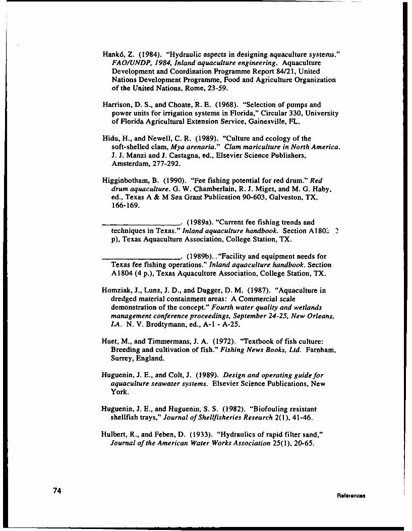
Hank6, Z. (1984). "Hydraulic aspects in designing aquaculture systems."FAO/UNDP, 1984, Inland aquaculture engineering. AquacultureDevelopment and Coordination Programme Report 84/21, UnitedNations Development Programme, Food and Agriculture Organizationof the United Nations, Rome, 23-59.
Harrison, D. S., and Choate, R. E. (1968). "Selection of pumps andpower units for irrigation systems in Florida," Circular 330, Universityof Florida Agricultural Extension Service, Gainesville, FL.
Hidu, H., and Newell, C. R. (1989). "Culture and ecology of thesoft-shelled clam, Mya arenaria." Clam mariculture in North America.J. J. Manzi and J. Castagna, ed., Elsevier Science Publishers,Amsterdam, 277-292.
Higginbotham, B. (1990). "Fee fishing potential for red drum." Reddrum aquaculture. G. W. Chamberlain, R. J. Miget, and M. G. Haby,ed., Texas A & M Sea Grant Publication 90-603, Galveston, TX,166-169.
(1989a). "Current fee fishing trends andtechniques in Texas." Inland aquaculture handbook. Section A180-' .2p), Texas Aquaculture Association, College Station, TX.
. (1989b).."Facility and equipment needs forTexas fee fishing operations." Inland aquaculture handbook. SectionA1804 (4 p.), Texas Aquaculture Association, College Station, TX.
Homziak, J., Lunz, J. D., and Dugger, D. M. (1987). "Aquaculture indredged material containment areas: A Commercial scaledemonstration of the concept." Fourth water quality and wetlandsmanagement conference proceedings, September 24-25, New Orleans,LA. N. V. Brodtymann, ed., A-1 - A-25.
Huet, M., and Timmermans, J. A. (1972). "Textbook of fish culture:Breeding and cultivation of fish." Fishing News Books, Ltd. Farnham,Surrey, England.
Huguenin, J. E., and Colt, J. (1989). Design and operating guide foraquaculture seawater systems. Elsevier Science Publications, NewYork.
Huguenin, J. E., and Huguenin, S. S. (1982). "Biofouling resistantshellfish trays," Journal of Shellfisheries Research 2(1), 41-46.
Hulbert, R., and Feben, D. (1933). "Hydraulics of rapid filter sand,"Journal of the American Water Works Association 25(1), 20-65.
74 References

Huner, J. V., and Dupree, H. K. (1984). "Production methods forbaitfish: Golden shiners and fathead minnows." Third report to thefish farmers. H. K. Dupree and J. V. Huner, ed., U.S. Fish andWildlife Service, Washington, DC, 83-89.
Jensen, G. L. (1988). Commercial production offarm-raised catfish.Louisiana State University Agricultural Center Publication, BatonRouge, LA.
Jensen, G. L., and Bankston, D. (1989). Guide to oxygen managementand aeration in commercialfish ponds. Louisiana State UniversityAgricultural Center Publication, Baton Rouge, LA.
Joint Subcommittee on Aquaculture of the Federal Coordinating Councilon Science, Engineering and Technology. (1983). Nationalaquaculture development plan. Volumes I and 2, Washington, DC.
Keenam, M. E., and Waldrop, J. E. (1988). "Economic analysis offarm-raised catfish production in Mississippi," Mississippi Agriculturaland Forestry Experiment Station Technical Bulletin 155, MississippiState, MS.
Keese, C. W. (1979). "Evaluating irrigation pumping plantperformance," Energy Information Leaflet 1718, Texas AgriculturalExtension Service, College Station, TX.
Keller, S. (1988). Proceedings of the fourth Alaska aquacultureconference, November 18-21, Sitka, AK. Alaska Sea Grant Report No.88-4, University of Alaska Fairbanks, AK.
Kovics, G., and Szll6si-Nagy, A. (1984). "Hydrological information fordesign and operation of aquaculture systems." FAO/UNDP, 1984,Inland aquaculture engineering. Aquaculture Development andCoordination Programme Report 84/21, United Nations DevelopmentProgramme, Food and Agriculture Organization of the United Nations,Rome, 9-22.
Kdvari, J. (1984a). "Preparation of plans and cost estimates and tenderdocuments." FAO/UNDP, 1984, Inland aquaculture engineering.Aquaculture Development and Coordination Programme Report 84/21,United Nations Development Programme, Food and AgricultureOrganization of the United Nations, Rome, 125-203.
_ (1984b). "Considerations in the selection ofsites for aquaculture." FAO/UNDP, 1984, Inland aquacultureengineering. Aquaculture Development and Coordination ProgrammeReport 84/21, United Nations Development Programme, Food andAgriculture Organization of the United Nations, Rome, 3-8.
Rfernce 75

K6vari, J. (1984c). "Hydraulic formulas used in designing fish farms."FAO/UNDP, 1984, Inland aquaculture engineering. AquacultureDevelopment and Coordination Programme Report 84/21, UnitedNations Development Programme, Food and Agriculture Organizationof the United Nations, Rome, 205-266.
LaCaze, C. (1976). "Crawfish farming," Fisheries Bulletin No. 7,Louisiana Department of Wildlife and Fisheries, Baton Rouge, LA.
Lee, J. S. (1981). Commercial catfish farming. Interstate Printers andPublishers, Danville, IL.
Louisiana Crawfish Farmers' Association. (1983). Proceedings of the13th Annual Meeting, September 10, 1983, Baton Rouge, LA.
Lunz, J. D., and Konikoff, M. (1987). "Use of dredged materialcontainment areas for aquaculture." Ecology and mangement ofwetlands. Volume 2: Management, use and value of wetlands. D. D.Hook, ed., Timber Press, Portland, OR, 292-295.
Magoon, C., and Vining, R. (1980). "Introduction to shellfishaquaculture in the Puget Sound region." Washington Department ofNatural Resources Handbook, Olympia, WA.
Mayo, R. D. (1988). The Bird song junction handbook. The MayoAssociates, Seattle, WA.
McVey, J. L., and Martin, R. J. (1980). "A Comparison of the cost ofthree pumping systems to provide water for catfish production." ForFish Farmers Newsletter 80-3, 2-9. Mississippi Cooperative ExtensionService, Stoneville, MS.
Murray, K. R., Wang, J., and Pruder, G. (1986). Aquacultureengineering. Elsevier Applied Science, Amsterdam.
Nailon, R. W. (1985). "Extensive grow-out systems for shrimp." Texasshrimp farming manual. G. W. Chamberlain, M. G. Haby, and R. J.Miget, ed., Texas Agricultural Extension Service Research andExtension Center, Corpus Christi, TX, IV-41 - IV-46.
New, M. B., and Sigholka, S. (1982). "Freshwater prawn farming," FAOFisheries Technical Paper (225), Food and Agriculture Organization ofthe United Nations, Rome.
Roland, B., and Gubbels, P. (1990). "Estimated costs and returns for aclam grow-out enterprise that supplements an existing oyster farm,January, 1990," Bulletin No. 33, Ministry of Agriculture and Fisheries,Victoria, BC.
76 References

Soil Conservation Service. (1969). "Ponds and reservoirs." EngineeringField Manual. Chapter 11, U.S. Department of Agriculture,Washington, DC.
(1971 a). "Ponds for water supply andrecreation." Agriculture Handbook 387. U.S. Department ofAgriculture, Washington, DC.
• (1971b). "Engineering practice standards,engineering conservation practices." National Engineering Handbook.Section 2, Part 1, U.S. Department of Agriculture, Washington, DC.
. (1982a). "Ponds-planning, design andconstruction." Agriculture Handbook No. 590. U.S. Department ofAgriculture, Washington, DC.
(1982b). "Aquaculture pumping plants forwater management," Engineering Technical Note, U.S. Department ofAgriculture, Washington, DC.
Strawn, K., Persbacher, P. W., Nailon, R., and Chamberlain, G. (1986).Raising mudminnows. Texas A & M Sea Grant Publication 86-506,College Station, TX.
Szilvissy, Z. (1984). "Soils engineering for design of ponds, canals anddams in aquaculture." FAO/UNDP, 1984, Inland aquacultureengineering. Aquaculture Development and Coordination ProgrammeReport 84/21, United Nations Development Programme, Food andAgriculture Organization of the United Nations, Rome, 79-101.
Tang, Y. A. (1979). "Physical problems in fish farm construction."Fishing News Books, Ltd. T. V. R. Pillay and W. A Dill, ed., Farnham,Surrey, England, 99-107.
Tatem, H. E. (1990). "Determination of the chemical suitability of adredged material containment area for aquaculture," Technical ReportEL-90-12, U.S. Army Engineer Waterways Experiment Station,Vicksburg, MS.
Tatum, W. M., Hawke, J. P., Minton, R. V., and Trimble, W. C. (1982)."Production of bull minnows (Fundulus grandis) for the live baitmarket in Alabama," Alabama Marine Resources Bulletin No. 13,Alabama marine Resources Laboratory, Dauphin Island, AL.
Tucker, C. S. (1985). Channel catfish culture. Elsevier SciencePublishers, New York.
Ulmer, R. (1987). Planning, design and construction of catfish ponds inMississippi. Soil Conservation Service publication, Jackson, MS.
References 77

Ulmer, R. (1990). "Pond design and construction." Red drumaquaculture. G. W. Chamberlain, R. J. Miget, and M. G. Haby, ed.,Texas A & M Sea Grant Publication 90-603, Galveston, TX, 147-153.
U.S. Army Corps of Engineers. (1987). "Confined disposal of dredgedmaterial," Engineer Manual EM 1110-2-5027, Department of theArmy, Washington, DC.
U.S. Department of Health and Human Services. (1989). Nationalshellfish sanitation program manual of operations. Part L Sanitationof shellfish growing areas. Food and Drug Administration,Washington, DC.
U.S. Department of the Interior. (1965). Earth manual: A Guide to theuse of soil as foundations and as construction materials for hydraulicstructures. IBH Publishing, Oxford, England.
Vaughn, D., Cresswell, L., and Pardee, M. (1988). "An Annual forfarming the hard shell clam in Florida," Aquaculture Report Series,Florida Department of Agriculture and Consumer Services,Tallahassee, FL.
Waas, B. P., Strawn, K., John, M., and Griffin, W. (1983). "TheCommercial production of mudminnows (Fundulus grandis) for livebait: A Preliminary economic analysis," Texas Journal of Science35(1), 51-60.
Wax, C. L_, and Pote, J. W. (1990). "A Climatological basis forconservation of groundwater in aquaculture in the southern region,"Mississippi Agricultural and Forestry Experiment Station TechnicalBulletin 169, Mississippi State, MS.
Wellborn, T. L. (1988). Site selection of levee-type fish productionponds. Southern Regional Aquaculture Publication No. 100,Stoneville, MS.
(1989a). Catfish farmers handbook.Mississippi Cooperative Extension Service, Mississippi State, MS.
(1989b). Construction of levee-type ponds forfish production. Southern Regional Aquaculture Publication No. 101,Stoneville, MS.
Wheaton, F. E. (1977). Aquacultural engineering. Wiley-Interscience,New York.
Wilson, C. A. (1990). "Extensive aquaculture of red drum in thesouthern United States." Red drum aquaculture. G. W. Chamberlain,R. J. Miget, and M. G. Haby, ed., Texas A & M Sea Grant Publication90-603, Galveston, TX, 154-164.
78 References

Wilson, J., Homziak, J., and Coleman, R. "Site selection, acquisition andplanning for aquaculture in dredged material containment areas,"Technical Report in preparation, U.S. Army Engineer WaterwaysExperiment Station, Vicksburg, MS.
York, R. H., Jr. n.d. "Growth of the clam Mercenaria mercenaria, inshrimp ponds," Unpublished manuscript, Hawaii Institute of MarineBiology, Kaneohe, HI.
References 79

General SpecificPurpose Objectives
DetermineRequirements
Constraints-Physical .-Physoical Synthesis and
-Economic Evaluation-Legal/PolitIcal/Social
Implementationand
Construction
Operations •II
Benefits
Figure 1. Schematic of a simplified design process (based on Huguenin and Colt (1989))

COHESIVE SOILS COHESIONLESS SOILS
LA SILT LOAM SADGRAVEL100
60 ~ I
201 1
.001 .01 .1110
GRAIN SIZE DIAMETER (MM)Figure 2. Semilogarithmic grain-size curves of soils (based on Kovari (1984b))
0*.9 0 O*. 0 0 0 O. 0 O a 0*.0 * 9..0 *.
IMPERMEABLE LAVE ~"g E (:.~*
Figure 3. Foundation cutoff for a dam built on permeable soil with an underlying imperme-able layer (based on Wheaton (1977))

a)UPSTREAM 1v2 -1.v24- DowNTREAM
SOat ýUPSTREAMM > OX DOWNSTREAM
b)UPSTREAM WfERMEAML CORE DOWSRA
h max h
Figure 4. Dam construction using an impermeable soil key for seepage reduction (fromSzilv~ssy (1984))

CONTROL STRUCTURE
EROSION-PREVENTION ......STRUCTURE
Figure 5. Simple drop inlet design with a combined mechanical and emergency spillway(based on Wheaton (1977))

FISH POND WU, A
Cross section of water control structure.
WALK• WAY
STOP LOGCLOUR
' 1 "
FISHRA SCEE
n
OWEE
CREST
,N W.L
/• 1.0 , ,MAX. t.80 , , 1.0 L , t0 • O
Longitudinal section of water control structure.
Figure 6. Reinforced concrete spillway with a recessed sill (based on Elekes (1984))
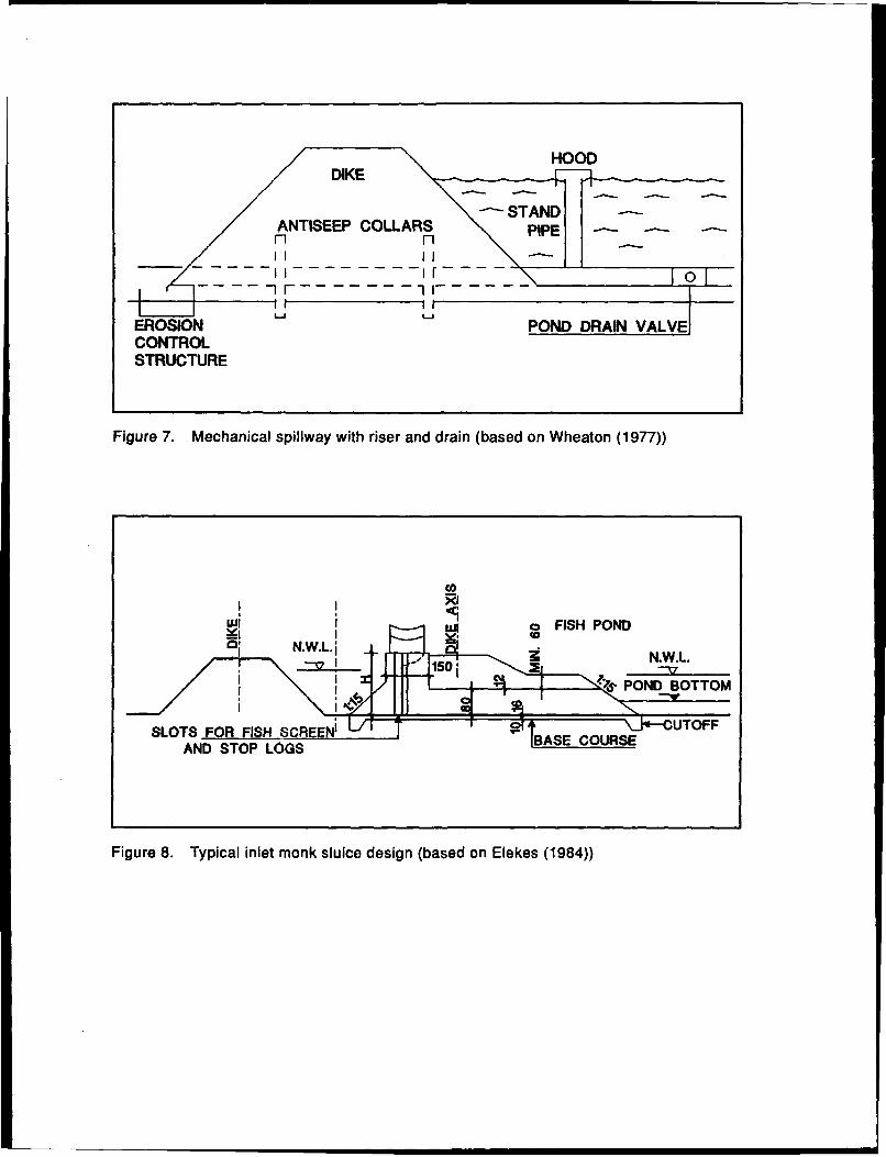
/• • HOOD~DIKE
EROSION POND DRAIN VALVECONTROLSTRUCTURE
Figure 7. Mechanical spillway with riser and drain (based on Wheaton (1977))
Co
Wi o FISH POND/' "N. 1 "T .[L.,• • N.W .L.
POND BOTTOM
SLOTS FOR FISH SCR EN BS COCUTOFFAND STOP LOGS .... . .....
Figure 8. Typical inlet monk sluice design (based on Elekes (1984))

FEEDER CANAL
.11~ -- w JlI
DRAINAGE CANAL
WI
INTERNAL POND DRAIN
3.0
DRAIN DITCH
Figure 9. Canal and ditch cross sections (based on Elekes (1984))

STA11T4ARY SCREE FL71ER AXIAL SCREE FILTERS
A) & ~ BACKWAS)
RAWIL FLOW FILTERS GAIYSMFLE
OPDIWOAAI ATRAL1
Ar-Ellt TRASH FFILEAWTER TNDISHA~ A~ ACIWAI4 SAM D
Fiue1.variou fitainLcendsinMbseEnWeto17)

DRAINAGE DITCH
-LEVEE
DRAIN LINE
660' 20 ACRES 20 ACRES
WELL '
i nlet
660' 20 ACRES DRAIN 20 ACRES
r1320' 1320'
Figure 11. Layout for typical catfish production ponds (based on Wellborn (1989a))

10 ACRES
F- FED I2.5 ACRES ACE
0.5 AC S-=:ACRES
LOPERATIONS BUILDING
Figure 12. Proposed design for a commercial saltwater fish farm (based on Ulmer (1990))

WATER INTAKE CANALWATER INTAKE CANAL
NURSERY TRANSITION
NUSR PON POND=
POND
REARING REARING REARING REARMPOND POND POND POND
1 2 3
WATER DISCHARGE CANAL WATER DISCHARGE CANAL
Figure 13. Shrimp pond layout for one nursery pond and three rearing ponds and for onenursery pond, one transition pond, and one rearing pond (from ASEAN (1978))

RIE BOARD ASSEMBLY
TIDE
TID
RIE BOARD ASS..EMBL Y
POND N
Figure 14. Wooden (A) and aluminum (13) water control structures for coastal impound-ments (from Wilgon (1990))

I--~VLM REIM mOARIA 4.aA .,be
VOLMIE NO
AVILA=,-
Figure15. Fowchar of dsign pocedYE frSetl n nta trg
ZON S ' ' ! I I I

MOUNDED COARSE-GRAINEDDREDGED MATERIAL
DEAD ZONE
-- . . .-- WEIR
AREA FOR SEDIMENTATION
-. .FLUENT
i - --..... - •/ • 1
DEAD ZONE----
PLAN
INFLUENT
PONDING DEPTH FREEBOARD
EFFLUENTCROSS SECTION
Figure 16. Conceptual diagram of a dredged material containment area
G . I I I

LAGUNA VISTA SOUTH PADRE
LOS FRESNOS ISLAND
OSI LAND
Fiuen thBownsle. Sp CCAAPh'neS. DEMONSTRATION! ..... ,...SITE :
BROWNSVILLE i,..'"" X
S~ MEXICO
SCALE1 _0 ,1 ,2 3 4 5 W
Figure 17. Location of project on the Brownsville Ship Channel

°• • POND A
Figure 18. Aerial view, looking north, of the DMCA selected for shrimp farm demonstra-tion. Also shown are BSC and elevated dunes or lomas

3.0 W""8.5EDG0
13 o. 10. 5 0.0 !432.0 7. a .5 6.0 70.0 1
3.0.8.
Fiur 1. pt leatos, eleaton ofprmte ie, otu leaino0rdematria mond, an0 loaton of0 inenltannMeee on ae-otostructur 9spi6bo0

INTAKE CANAL
Figure 20. Aerial photograph of existing disposal site showing outlines of Pond A andmajor earthworks

•'~2 IN. ...
NWE SHP PANU .4 Y-4V 0 SVE
Section A
2
Section B
Figure 21. Cross sections of planned dikes for both ponds, showing dimensions, slopes,and elevations. Section A illustrates a typical dike cross section; Section Bshows a dike cross section where borrow material is excavated
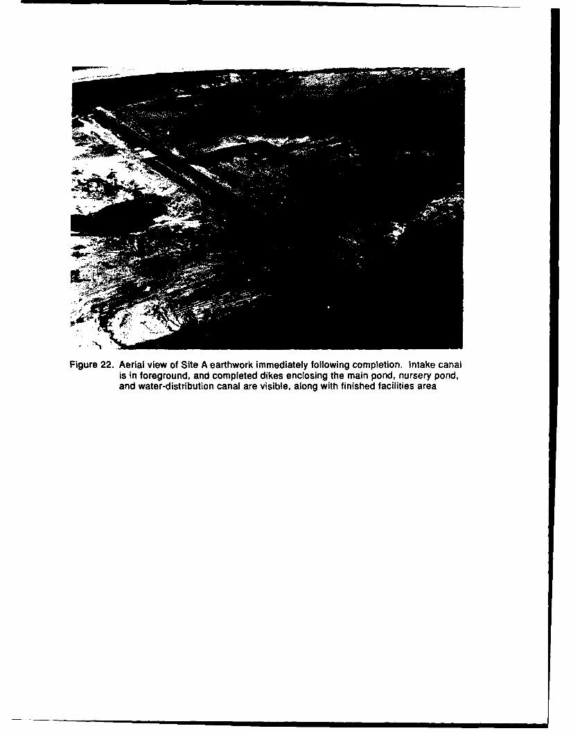
Figure 22. Aerial view of Site A earthwork immediately following completion. Intake canalis in foreground, and completed dikes enclosing the main pond, nursery pond,and water-distribution canal are visible, along with finished facilities area

BROWNSVILLE SHIP CHANNEL "•iWATER
:] • i:::INTAKE-------------WATE
B/STRAG NURERYCANAL
-- WATER
GROWOUT POND R DISTRIBUTION100 AC. i -" STRUCTURE
Figure 23. Sketch showing planned locations of buildings and other site features on ornear facilities area

SCREENOVERFLOW SHUNT DRAIN
FILTER SCREEN
E ý D-- , SLOTTED FILTER
On-• STANDPIPE
WATER FLOW
Figure 24. General view of predator filter

Figure 28. Predator filter in operation with the cover removed, looking south down water-distribution canal. Discharge pipes are in foreground

Figure 26. View of nursery pond inlet from within nursery pond, showing screens in place

LEVEE SIDES IPOND 'A'
LEVEE TOP FOOTBRIDGE 4
STr 14TPLG
T STOPLOGS
L~ u J. -1 "OF CONCRETE 9L
FOOTBRIDGE
S T7
WATER FLOW
Figure 27. Sketch of structure showing an overhead view. Large arrows indicate directionof water flow

STOP LOGO
oFLgurEeW 2 S ie v e e PLouc
Figure 28. Simplified overhead view of Pond A harvest structure

Figure 29. View of water-control/harvest structure from within Pond A, with lower tier ofscreens in place

Figure 30. Aerial view, looking south, of completed Pond A facilities. All major structuresand site components in place and nursery pond in operation. Note water-con-trol/harvest structure on the right, in Pond A levee. Modified equipment areafor harvest operations is visible on both sides of structure. Pond B, on theleft, is under construction

Figure 31. General view of Pond A water-controllharvest structure during harvest

REPORT DOCUMENTATION PAGE Form ApoeOMB No. 0704-0188
Public reporting burden for t cftforrn ollnbrnmon fome•etemed to aveage I hourper response, indudngUtheime forrevlwing nsnctions. searching existingdatasources, gathetnn and maintainingthe data needsd. and conmpletng and reviewing the colection of infornation. Send oornments regarding this burden esomate or any other aspect o this collection of information, irnclcing suggestionsfr eIdng Ot bu•iden. to WasNngton Headquart Services, Directoade for Infornlaton Operations and Reports. 1215 Jeffetson Davis Highway. Suite 1204, Arington, VA 22202-4302. and 0o theOkffio dmiegewient and k•got. Paperwork Reduction Project (0704-0188). Washington, DC 20503.
1. AGENCY USE ONLY (Leave blank) 2. REPORT DATE 3. REPORT TYPE AND DATES COVERED
July 1993 Final report
4. TITLE AND SUBTITLE 5. FUNDING NUMBERSDesign and Construction of Aquaculture Facilities in Dredged MaterialContainment Areas
6. AUTHOR(S)Jurij Homziak, C. David Veal, Donald Hayes
7. PERFORMING ORGANIZATION NAME(S) AND ADDRESS(ES) 8. PERFORMING ORGANIZATIONSea Grant Advisory Service, Mississippi Cooperative Extension Service, Mississippi REPORT NUMBERState University Coastal Research and Extension Center, 27 10 Beach Boulevard, Suite Technical Report EL-93- 11lE, Biloxi, MS 39531; U.S. Army Engineer Waterways Experiment Station, Environ-mental Laboratory, 3909 Halls Ferry Road, Vicksburg, MS 39180-6199
9. SPONSORING/MONITORING AGENCY NAME(S) AND ADDRESS(ES) 10. SPONSORINGIMONITORING
U.S. Army Corps of Engineers AGENCY REPORT NUMBER
Washington, DC 20314-1000
11. SUPPLEMENTARY NOTES
Available from National Technical Information Service, 5285 Port Royal Road, Springfield, VA 22161.
122. DISTRIBUTION/AVAILABILITY STATEMENT 12b. DISTRIBUTION CODEApproved for public release; distribution is unlimited.
13. ABSTRACT (Maximum 200 words)
Aquaculture as a multiple use of dredged material containment areas (DMCA) has been investigated by the Containment AreaAquaculture Program (CAAP). This report describes design and construction of aquaculture pond facilities in DMCA, reviews de-sign, construction, and operation of DMCA for material disposal, and documents the design and construction of the CAAP ShrimpFarm Demonstration Facility in Brownsville, TX.
A complete overview of the entire planning process that leads up to the start of aquaculture facility construction is provided. Re-views are given of site selection principles and aquaculture engineering concepts. The approaches are also reviewed that are usedto design and construct aquaculture facilities, based on established aquaculture engineering and design principles, incorporation ofsite conditions, preparation of feasibility and project plans, methods of estimating project costs, and decision-making criteria forproject implementation. The review includes a stepwise guide to aquaculture project planning, including definition of project objec-tives, iterative planning and preparation of feasibility study, and final project reports.
The planning process requires the preparation of a detailed production plan relating project objectives to site conditions. Thestructure of a production plan and the process of designing the aquaculture facility using site data and production requirements is de-scribed. Particular attention is paid to developing design criteria and specifications, descriptions of facilities, and schedules of
(Continued)14. SUBJECT TERMS 15. NUMBER OF PAGES
Aquaculture CAAP 116Beneficial uses DMCA
16. PRICE CODE
17. SECURITY CLASSIFICATION 16. SECURITY CLASSIFICATION 19. SECURITY CLASSIFICATION 20. LIMITATION OF ABSTRACT
OF REPORT OF THIS PAGE OF ABSTRACT
UNCLASSIFIED UNCLASSIFIED
NSN7540-01-280-5500 Standard Form 298 (Rev. 2-89)Prescribed by ANSI Std. Z39-1 8
298-102

13. (Can•uded.
execution/completion. The preparation of cost estimates and contractual documents are also considered. Examplesof commercial pond-based production designs used in the United States are presented to illustrate end products ofsuccessful planning efforts.
DMCA design and operations are briefly reviewed. Design considerations include the dredging and disposal op-erations, effluent quality, and storage capacity requirements. These, in turn, determine DMCA structural elements.Critical to designing a dual use DMCA facility for aquaculture is an understanding of the management and operationof the DMCA before, during, and after dredging operations.
This report also serves to document the design and construction of the Shrimp Farm Demonstration Facility, afield demonstration of aquacultute as a compatible use of active DMCA. The demonstration project objectives, siteselection and characteristics, preparation of the production plan, data collection and analysis for the feasibility study,completion of design specifications and final project plans, and the influence of site characteristics and dredgingproject requirements on facility design are reviewed. The design and construction of all major site components aredocumented, including earthwork and canals, concrete water control and distribution structures, buildings, ma-chinery, and related onsite facilities.