design and analysis of a novel six-component f/t sensor ... · on cpm for passive compliant...
TRANSCRIPT
MEASUREMENT SCIENCE REVIEW, Volume 13, No. 5, 2013
253
Design and Analysis of a Novel Six-Component F/T Sensor based
on CPM for Passive Compliant Assembly
Qiaokang Liang1, Dan Zhang
2, Yaonan Wang
1, Yunjian Ge
3
1College of Electric and Information Technology, Hunan University, Changsha, Hunan 410082, China,
[email protected] 2Faculty of Engineering and Applied Science, University of Ontario Institute of Technology, Oshawa, Ontario,
Canada L1H 7K4, [email protected] 3State Key Laboratories of Transducer Technology, Institute of Intelligent Machines, Chinese Academy of Science, Hefei,
Anhui 230031, China, [email protected]
This paper presents the design and analysis of a six-component Force/Torque (F/T) sensor whose design is based on the
mechanism of the Compliant Parallel Mechanism (CPM). The force sensor is used to measure forces along the x-, y-, and z-axis
(Fx, Fy and Fz) and moments about the x-, y-, and z-axis (Mx, My and Mz) simultaneously and to provide passive compliance during
parts handling and assembly. Particularly, the structural design, the details of the measuring principle and the kinematics are
presented. Afterwards, based on the Design of Experiments (DOE) approach provided by the software ANSYS®, a Finite Element
Analysis (FEA) is performed. This analysis is performed with the objective of achieving both high sensitivity and isotropy of the
sensor. The results of FEA show that the proposed sensor possesses high performance and robustness.
Keywords: Compliant Parallel Mechanism, Passive Compliant Assembly, Six-component F/T sensor.
1. INTRODUCTION
INCE the Oak Ridge and Argonne National Laboratories applied force feedback on the load the slave manipulator encountered to their master-slave manipulator during the
late 1940s, F/T sensing with appropriate control techniques has played an important role in the dexterous and reliable robotic manipulation. After F/T control has been recognized as a key scheme for using robots in advanced applications [1], various types of F/T sensors have been designed and developed [2-6]. Several six-axis force sensors are commercially available at present, such as force sensors of ATI [7] and JR3.
A major problem in developing force sensors is the design of the force-sensing element, which has been done heuristically, dependent on the experience of designers [1]. To detect three orthogonal forces and three orthogonal torques simultaneously, the force-sensing elements of multi-component force sensors are always featured by complicated geometrical structures, which make accurate calculation of strains and deflection difficult or even impossible with current techniques. Another critical drawback of the traditional multi-component F/T sensor is the existence of significant measurement couplings among components, especially between component Mx and component Fy, component My and component Fx. Additionally, as there are six components to be measured and processed simultaneously, approximately equal measurement sensitivity for each component is expected [8], [9]. Furthermore, the stiffness and the sensitivity of the F/T sensor is always a trade-off, which means users have to make a sacrifice of stiffness to get a high-sensitivity performance and vice versa.
Taking into account the above-mentioned drawbacks, researchers found that parallel mechanisms are preferred to be considered as a candidate for a force-sensing element of a multi-component F/T sensor due to their following advantages [6].
1. Relative maturity of the theory system: all the related
theory, such as position analysis, statics, stiffness analysis,
dynamics, have been investigated for a long time and gotten
well known;
2. Possibility to provide decoupling F/T information: unlike
traditional force-sensing elements that sense all F/T
components with a single monolithic structure, force-
sensing elements based on parallel mechanisms employ their
limbs to sense the components and show a limited cross talk; 3. Isotropy: based on the statics analysis of parallel
mechanisms, a global stiffness matrix denoting the
relationship between the undergoing load and the
infinitesimal movement of the mobile platform can be
obtained, which could be used to pursue measurement
isotropy among components;
4. High stiffness and high sensitivity: as the stiffness of the
robotic manipulator depends on the component with
minimum stiffness, which is always the F/T sensor, the
stiffness of a F/T sensor is a critical performance factor.
However, it is impossible for a traditional force-sensing
element of high stiffness to detect F/T with high sensitivity.
On the contrary, for the force-sensing element based on
parallel mechanisms, the limb stiffness can be much lower
compared to the overall required stiffness of the F/T sensor
due to their parallel arrangement. Therefore, the trade-off
between stiffness and sensitivity can be solved.
Recently, some researchers developed force/torque sensors
based on parallel mechanisms to meet the requirement and
escape the mentioned shortcoming [6]. Gailet and Reboulet
developed a force sensor of SP (Stewart Platform) based on
octahedral structure [10]. Dwarakanath and Bhaumick
designed and implemented a force/torque sensor based on
the SP structure in 1999, and the analysis deals with
kinematic design, leg design and optimization of the form
of the leg and the aspects of integration were presented [11].
S
10.2478/msr-2013-0038
MEASUREMENT SCIENCE REVIEW, Volume 13, No. 5, 2013
254
Table 1. Comparisons on the multi-dimensional F/T sensor.
Year &
developer
Fabrication
technology
Size
(mm)
& No.
of axes
Sensitivity &
Measurement
range
Sensing
principl
e
1998 & Jin
and Mote
Bulk silicon
micro-machining and
wafer-bonding
technologies
4.5 ×
4.5 × 1.2 & 6
1 mN and 2 mN
mm for force and moment
components
(resolutions) & n.a.
Piezo-
resistive
1999 & Mei et al.
CMOS process,
silicon bulk micro-
machining
4×4×2 & 3
13mV/N in the Z-axis and
about 2.3mv/N in X- and Z-axis
& 0—50 N in
Z-axis, ±10N in X- and Y-axis
Piezo-resistive
2012 & Brookhuis,
Lammerink
Bulk silicon Micro-
machining and
silicon fusion bonding
9×9×1
(PCB chip)
& 3
16 PF/N in Fz and 2.7PF/N
mm in Mx and
My & 50N in Fz, ±25 N mm
in Mx and My
Capaci-tive
2009 &
Takenawa, S.
Four chip
inductors, silicone gel,
and a
neodymium magnet
3.2×
2.5 × 2.2 & 3
0.06 N
(resolution) & -40 N to 40 N
Inducti-
ve
2011 & M.
Gobbi et al.
Three spoke
structure,
standard mechanical
machining
40.25×
16 × 16
& 6
95%
(uncertainty) &
10 kN (Fz), 5 kN (Fx, Fy) and
0.5 kNm (M)
Strain
gauge
2004 & Liu,
Inoue et al.
Parallel
support mechanism &
machining
170×10
5×26.5 & 6
Fx=Fy=20kgf,
Fz=l00kgf, and Mx=My=Mz=l0
0 Nm
Strain
gage
1990 &
Hirose and Yoneda
Three
elastomers in a flexed spoke
shape &
milling and electric
discharge
machining
Φ76×4
0 & 6
0.3% & 100 kgf
and 300kgfcm for parallel and
rotating
directions, respectively
Optical
2010 & Jia,
Lin, and Liu
Stewart
platform & standard
mechanical
machining
small
than Φ160 ×
210
linear error and
the repeatability error of 1%,
interference
error of 4.5% & 40kN and
5kNm for force
and moment components
Piezo-
electric
Ranganath, Mruthyunjaya and Ghosal analyzed and designed a SP-based force/torque sensor in a near-singular configuration with high sensitivity [12]. Nguyen, Antrazi and Zhou presented the kinematic analysis of a 6 DOF force/torque sensor based on the mechanism of the Stewart Platform and composed of two platforms coupled together by 6 spring-loaded pistons [13]. Dasgupta, Reddy and Mruthyunjaya presented a design methodology for the Stewart Platform sensor structure based on the optimal conditioning of the force transformation matrix [14]. Hou, Zeng, Yao et al. presented a six-component F/T sensor
based on a hyperstatic Stewart Platform. Parameter optimization of the sensor structure was performed with genetic algorithms, and the sensor shows good isotropy and sensitivity performances [15]. Recently, Jia, Lin, and Liu introduced another type of Stewart Platform dedicated to heavy six-axis load sharing measurement [16], [17]. With single-component force piezoelectric sensor fixed in each limb, the sensor could measure six-component F/T with linear and repeatability error of 1%. The comparisons of main features and characterization methods using a selection of multi-dimensional F/T sensors up to the date of the publication are shown in Table 1.
Unfortunately, in force-sensing applications, the presence of clearance, friction and backlash at the rigid mechanical joints of parallel mechanisms will modify the axial forces that the limbs are subjected to, therefore, disturb the performance of the sensor in unpredictable ways. To avoid these problems, force-sensing candidate based on parallel mechanism is preferred to be designed with flexural joints, which eliminate the friction, backlash and wear and possess sub-micron accuracy with high resolution, continuous and smooth displacement.
In this paper, modeling and performance evaluation of a novel six-component force/torque sensor based on compliant parallel mechanism is presented, which consists of three identical sensing limbs of type SPS (Spherical-Prismatic-Spherical) and one central leg with three degrees of freedom. The compliant joints of the four limbs are employed as active force-sensing portions. By the electric measurement technique of strain gauge, the developed sensor can provide high-performance force/torque information, and the calibration experiment shows that the presented sensor possesses positive characteristics such as high stiffness and sensitivity, weak couplings, and good isotropy.
2. ARCHITECTURE DESCRIPTION OF THE SENSOR
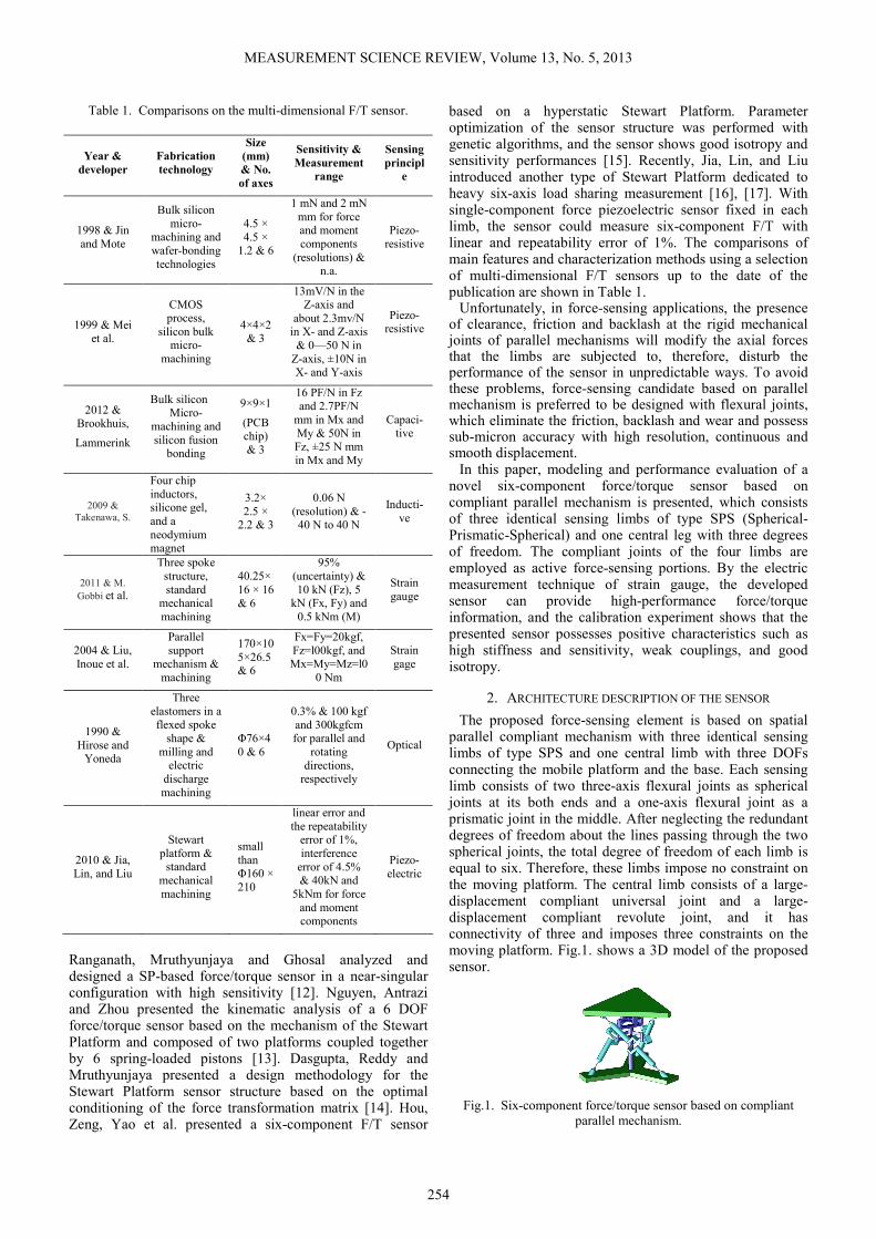
The proposed force-sensing element is based on spatial parallel compliant mechanism with three identical sensing limbs of type SPS and one central limb with three DOFs connecting the mobile platform and the base. Each sensing limb consists of two three-axis flexural joints as spherical joints at its both ends and a one-axis flexural joint as a prismatic joint in the middle. After neglecting the redundant degrees of freedom about the lines passing through the two spherical joints, the total degree of freedom of each limb is equal to six. Therefore, these limbs impose no constraint on the moving platform. The central limb consists of a large-displacement compliant universal joint and a large-displacement compliant revolute joint, and it has connectivity of three and imposes three constraints on the moving platform. Fig.1. shows a 3D model of the proposed sensor.
Fig.1. Six-component force/torque sensor based on compliant
parallel mechanism.

MEASUREMENT SCIENCE REVIEW, Volume 13, No. 5, 2013
255
Fig.2. shows the link-pair relationship diagram for the 3-
DOF mechanism. The blue boxes represent passive joints
while the red boxes represent sensing joints, which are used
as the elastic element of the sensor. The number of degrees
of freedom, Fd, is given by the Chebyshev-Grubler-
Kutzbach criterion:
1
( 1)
6 (9 11 1) 24 3 3
j
d i r
i
F n j f fλ=
= − − + −
= × − − + − =
∑
(1)
Where λ denotes the dimension of the space, n and j
denote the number of links and the number of joints,
respectively, fi and fr represent the degree of freedom
associated with joint i and the number of redundant degrees
of freedom in the mechanism.
Fig.2. Schematic diagram of the compliant parallel mechanism.
The notch hinges and the leaf type flexure are probably the
most popular element in applications of compliant
mechanisms. All compliant joints used in this design are
shown in Fig.3.
(a) (b) (c)
Fig.3. Compliant joints used in the design: (a) compliant spherical
joint; (b) compliant prismatic joint; (c) compliant spherical joint for
central limb.
Toroidal notch hinge, as shown in Fig.3(a)., is commonly
utilized in spatial compliant mechanisms to provide 3-axis
motions [25], [26]. The equation for the stiffness in the
freedom axes can be approximated from [27], [28].
7/2
1/220
y x
y x
M M Et
Rθ θ= ≈
(2)
7/2
3/220
yx
y x
FF Et
Rθ θ= ≈
(3)
3/2
1/22
z
z
F Et
Rδ≈
(4)
Where Fn and δn are the force and translation displacement
in n-axis, respectively; t and R are the inter-hole space and
common radius of notches, respectively; and Mn and θn are
the moment and rotational displacement around n-axis,
respectively; the E is modulus of longitudinal elasticity of
the material.
The majority of the existing compliant translational joints
are based on a parallel four-bar building block [29]. Though
they can deliver a pure translational motion with acceptable
off-axis stiffness, the range of motion is very limited and the
construction is complicated. A novel compliant translational
joint based on a simple cantilever is proposed and shown in
Fig.3(b).
Due to its geometry character (as shown in Fig.4.), the
applied force Fy is transmitted to the beam through a drive
bar with an additional bending moment Mz. The bending
equation for this particular leaf spring is given by
2
2( ) ( )
2 2
y
y y y
d L LEI F F L x F x
dx
δ= − − = −
(5)
Integrating twice with boundary conditions and assuming
small displacements, then,
21( )2 2
y
LEI F x xθ = −
(6)
3 21( )6 4
y y
LEI F x xδ = −
(7)
The slope and deflection at the free end of the beam can be
obtained
21( ) 02 2
y
x L
F Lx x
EIθ
== − =
(8)
3
3 21( )6 4 12
y
y yx L
F L Lx x F
EI EIδ
== − = −
(9)
The compliant spherical joint for central limb used in this
study, which was designed by Trease [25], [26], is shown in
Fig.3(c).
Fig.4. The configuration of the cantilever.
MEASUREMENT SCIENCE REVIEW, Volume 13, No. 5, 2013
256
3. KINEMATICS
The pseudo-rigid-body model provides a simple method of
analyzing compliant systems that undergo large, nonlinear
deflections and is used to model the deflection of flexible
members using rigid-body components that have equivalent
force-deflection characteristics. Therefore, rigid-link
mechanism theory may be used to analyze the compliant
mechanism [31], [32].
A. Inverse and forward kinematics
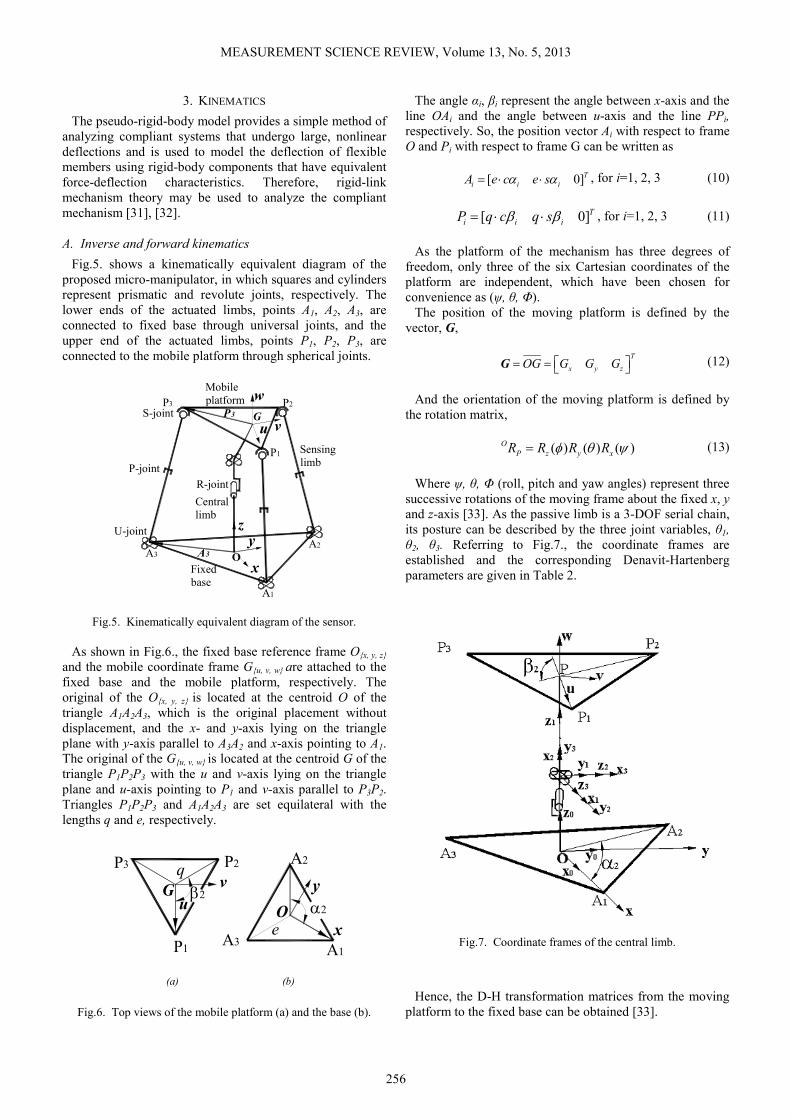
Fig.5. shows a kinematically equivalent diagram of the
proposed micro-manipulator, in which squares and cylinders
represent prismatic and revolute joints, respectively. The
lower ends of the actuated limbs, points A1, A2, A3, are
connected to fixed base through universal joints, and the
upper end of the actuated limbs, points P1, P2, P3, are
connected to the mobile platform through spherical joints.
x
yz
u
w
v
O
P2
P1
A1
A2
P3
A3A3
P3
P-joint
R-joint
U-joint
S-joint
Sensing
limb
Central
limb
Fixed
base
Mobile
platform
G
Fig.5. Kinematically equivalent diagram of the sensor.
As shown in Fig.6., the fixed base reference frame O{x, y, z}
and the mobile coordinate frame G{u, v, w} are attached to the
fixed base and the mobile platform, respectively. The
original of the O{x, y, z} is located at the centroid O of the
triangle A1A2A3, which is the original placement without
displacement, and the x- and y-axis lying on the triangle
plane with y-axis parallel to A3A2 and x-axis pointing to A1.
The original of the G{u, v, w} is located at the centroid G of the
triangle P1P2P3 with the u and v-axis lying on the triangle
plane and u-axis pointing to P1 and v-axis parallel to P3P2.
Triangles P1P2P3 and A1A2A3 are set equilateral with the
lengths q and e, respectively.
y
xA3
A1
A2
e
P3
v
uO
G
P2
P1
q
α2
β2
(a) (b)
Fig.6. Top views of the mobile platform (a) and the base (b).
The angle αi, βi represent the angle between x-axis and the
line OAi and the angle between u-axis and the line PPi,
respectively. So, the position vector Ai with respect to frame
O and Pi with respect to frame G can be written as
[ 0]T
i i iA e c e sα α= ⋅ ⋅ , for i=1, 2, 3
(10)
[ 0]T
i i iP q c q sβ β= ⋅ ⋅ , for i=1, 2, 3
(11)
As the platform of the mechanism has three degrees of
freedom, only three of the six Cartesian coordinates of the
platform are independent, which have been chosen for
convenience as (ψ, θ, Φ).
The position of the moving platform is defined by the
vector, G,
T
x y zOG G G G = = G
(12)
And the orientation of the moving platform is defined by
the rotation matrix,
( ) ( ) ( )O
P z y xR R R Rφ θ ψ=
(13)
Where ψ, θ, Φ (roll, pitch and yaw angles) represent three
successive rotations of the moving frame about the fixed x, y
and z-axis [33]. As the passive limb is a 3-DOF serial chain,
its posture can be described by the three joint variables, θ1,
θ2, θ3. Referring to Fig.7., the coordinate frames are
established and the corresponding Denavit-Hartenberg
parameters are given in Table 2.
Fig.7. Coordinate frames of the central limb.
Hence, the D-H transformation matrices from the moving
platform to the fixed base can be obtained [33].
MEASUREMENT SCIENCE REVIEW, Volume 13, No. 5, 2013
257
Table 2. The D-H parameters of the passive constraining limb.
i ai di αi θi
1 0 l1 0 θ1
2 0 0 -π/2 θ2
3 0 0 -π/2 θ3
G 0 l4 0 0
1 2 3 1 2 3 4 3 11 2
1 3 1 3 1 2 3
1 2 3 1 2 3 4 1 31 2
1 3 1 3 2 1 3
2 3 2 2 3 1 4 2 3
1 2 3
(-- )
(- - )
-
0 0 0 1
0 1
O O
O P
P P
c c c c c s l c sc s
s s s c c c s
s c c s c s l c cs s
c s s c c s s
s c c s s l l s s
R GT TT T T
θ θ θ θ θ θ θ θθ θθ θ θ θ θ θ θ
θ θ θ θ θ θ θ θθ θθ θ θ θ θ θ θ
θ θ θ θ θ θ θ
+ +
= +
+
= =
(14)
Comparing (13) to (14), one can yield
1
2 ( )cos c sθ θ ψ−=
(15)
3
2 2
s c sAtan2( , )
s c
θ ψ θθ
θ θ−
=
(16)
1
2 2
s s s c c s cAtan2( , )
s s
φ θ ψ φ ψ φ θθ
θ θ+
=
(17)
The inverse kinematics problem can be simply stated as:
given the independent parameters, ψ, θ, Φ, to find the
corresponding lengths of the actuated limbs:
[ ] [ ]O P T O P
i i P i i P id G A R P G A R P= − + − +
(18)
For the forward kinematics, the limb lengths l1, l2, and l3
are given and the problem is to find the orientation of the
mobile platform. (18) is written in the following form [33]:
1 1 2 3 2 1 2 3 3 1 3
4 1 3 5 1 2 6 1 2
7 3 3 8 2 9 0
i i i
i i i
i i i
c c c s c c s s
c s s s c s
c s c
µ θ θ θ µ θ θ θ µ θ θ
µ θ θ µ θ θ µ θ θ
µ θ θ µ θ µ
+ +
+ + +
+ + + =
for i=1, 2, 3 (19)
Where ijµ are constant coefficients that are determined by
the manipulator geometry and input leg lengths [33].
B. Jacobian matrix
Since the mechanism possesses only three rotational
degrees of freedom, the input vector can be written as the
extension rate of the sensing limbs1 2 3, ,
T
d d d = d & & && , and the
output vector can be presented as the angular velocity of the
moving platform, , ,T
x y zω ω ω = X& By using the velocity
vector-loop method, we can obtain the Jacobian matrix of
the mechanism A without the passive leg,
A =X d& & (20)
Where
( )( )( )
1 1 1
2 2 2
3 3 3
TT
TT
TT
A
×
= × ×
s P s
s P s
s P s
(21)
And si is the unit vector pointing along the ith limb.
The Jacobian matrix of the passive constraining leg of the
mechanism B can be expressed as
1 2 3
1 1 2 2 3 3
4 1 3 4 1 2 34 1 2 3
2 1 3 1 3
4 1 3 4 2 3 14 2 1 3
1 2 3 1 3
4 2 3 4 3 2
1 1 2
1 1 2
2
( () )
( () )
0
0
0
1 0
e e eB
e r e r e r
l c c l c c cl c s s
c s s s s
l s c l c c sl s s s
c c s c s
l c s l c s
s c s
c c s
c
θ θ θ θ θθ θ θθ θ θ θ θ
θ θ θ θ θθ θ θθ θ θ θ θ
θ θ θ θθ θ θθ θ θ
θ
= × × ×
− − +
− −− − =
−
−
(22)
Hence,
2 21 1 1 1 2 3
2 2
c cc s
s s
θ θθ θ ω θ ω ω
θ θ= + +&
(23)
2 1 1 1 2s cθ θ ω θ ω= −&
(24)
1 13 1 2
2 2
c s
s s
θ θθ ω ω
θ θ= +&
(25)
J, a 3x3 Jacobian matrix, relating the independent velocity
variables of mobile platform, X& , to the vector of sensing
limb rates, d& .
3 3
st
JA AJ J
I ×
= = = d X X X& & & &
(26)
MEASUREMENT SCIENCE REVIEW, Volume 13, No. 5, 2013
258
Where, Jt, a 6×3 Jacobian matrix, relating the velocity state
of the moving platform, T
G x y zG G G = v & & & , to the
vector of sensing limb extension rates. And Js, a 3×3
Jacobian matrix, relating the three independent velocities X&
to the three dependent velocities Gv , which could be
obtained through (22) to (25).
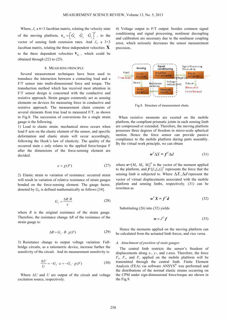
4. MEASURING PRINCIPLE
Several measurement techniques have been used to
transduce the interaction between a contacting load and a
F/T sensor into multi-dimensional force and torque. The
transduction method which has received most attention in
F/T sensor design is concerned with the conductive and
resistive approach. Strain gauges commonly act as sensing
elements on devices for measuring force in conductive and
resistive approach. The measurement chain consists of
several elements from true load to measured F/T, as shown
in Fig.8. The succession of conversions for a single strain
gauge is the following.
1) Load to elastic strain: mechanical stress occurs when
load F acts on the elastic element of the sensor, and specific
deformation and elastic strain will occur accordingly,
following the Hook’s law of elasticity. The quality of the
occurred stain ε only relates to the applied force/torque F
after the dimensions of the force-sensing element are
decided.
( )Fε χ= (27)
2) Elastic strain to variation of resistance: occurred strain
will result in variation of relative resistance of strain gauges
bonded on the force-sensing element. The gauge factor,
denoted by Gf, is defined mathematically as follows [34].
f
R RG
ε∆
= (28)
where R is the original resistance of the strain gauge.
Therefore, the resistance change ∆R of the resistance of the
strain gauge is:
( )fR G R Fχ∆ = ⋅ ⋅ (29)
3) Resistance change to output voltage variation: Full-
bridge circuits, as a ratiometric device, increase further the
sensitivity of the circuit. And its measurement sensitivity is:
( )f f
UG G F
Uε χ
∆= − ⋅ = − ⋅
(30)
Where ∆U and U are output of the circuit and voltage
excitation source, respectively.
4) Voltage output to F/T output: besides common signal
conditioning and signal processing, nonlinear decoupling
and calibration are necessary due to the nonlinear coupling
error, which seriously decreases the sensor measurement
precision..
Fig.8. Structure of measurement chain.
When resistive moments are exerted on the mobile
platform, the compliant prismatic joints in each sensing limb
are compressed or extended. Therefore, the moving platform
possesses three degrees of freedom in micro-scale spherical
motion. Hence the force sensor can provide passive
compliance to the mobile platform during parts assembly.
By the virtual work principle, we can obtain
T TX d∆ ∆w = f
(31)
where w=[Mx, My, Mz]
T is the vector of the moment applied
to the platform, and f=[f1,f2,f3]T represents the force that the
sensing limb is subjected to. Where ,X d∆ ∆ represent the
vector of virtual displacements associated with the mobile
platform and sensing limbs, respectively. (31) can be
rewritten as
T T &&w X = f d
(32)
Substituting (26) into (32) yields
TJ=w f
(33)
Hence the moments applied on the moving platform can
be calculated from the actuated limb forces, and vice versa.
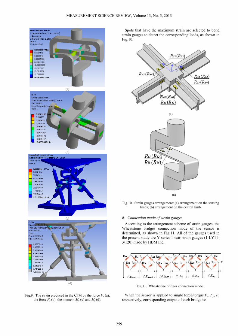
A. Attachment of position of stain gauges
The central limb restricts the sensor’s freedom of
displacements along x-, y-, and z-axis. Therefore, the force
Fx, Fy, and Fz applied on the mobile platform will be
transmitted through the central limb. Finite Element
Analysis (FEA) via software ANSYS® was performed and
the distributions of the normal elastic strains occurring on
the CPM under sign-dimensional force/torque are shown in
the Fig.9.
MEASUREMENT SCIENCE REVIEW, Volume 13, No. 5, 2013
259
(a)
(b)
(c)
(d)
Fig.9. The strain produced in the CPM by the force Fx (a),
the force Fz (b), the moment Mx (c) and Mz (d).
Spots that have the maximum strain are selected to bond
strain gauges to detect the corresponding loads, as shown in
Fig.10.
(a)
(b)
Fig.10. Strain gauges arrangement: (a) arrangement on the sensing
limbs; (b) arrangement on the central limb.
B. Connection mode of strain gauges
According to the arrangement scheme of strain gauges, the
Wheatstone bridges connection mode of the sensor is
determined, as shown in Fig.11. All of the gauges used in
the present study are Y series linear strain gauges (1-LY11-
3/120) made by HBM Inc.
Fig.11. Wheatstone bridges connection mode.
When the sensor is applied to single force/torque Fx, Fy, Fz
respectively, corresponding output of each bridge is:
MEASUREMENT SCIENCE REVIEW, Volume 13, No. 5, 2013
260
4341 42 44
41 42 43 44
41 42
41 42
41 42
4
2 24
( )2
Fz
RR R RUU
R R R R
R RU
R R
UK
ε ε
ε ε
∆∆ ∆ ∆∆ = − + −
∆ ∆= −
= +
(34)
51 52 53 54
51 52 53 54
51 52
51 52
51 52
4
2 24
( )2
Fx
R R R RUU
R R R R
R RU
R R
UK
ε ε
ε ε
∆ ∆ ∆ ∆∆ = − + −
∆ ∆= −
= +
(35)
61 62 63 64
61 62 63 64
61 62
61 62
61 62
4
2 24
( )2
Fy
R R R RUU
R R R R
R RU
R R
UK
ε ε
ε ε
∆ ∆ ∆ ∆∆ = − + −
∆ ∆= −
= +
(36)
Where K is the sensitivity coefficient of the strain gauges,
εi is the elastic strain at the spot where the Ri is bonded on
the diaphragms, U is the excitation voltage, and ∆Ri/Ri
means change rate of the resistance of the strain gauge Ri
due to strain variation.
The corresponding output of each sensing limb can be
calculated as
1311 12 14
11 12 13 14
11 12
11 12
11 12
limb14
2 24
( )2
RR R RUU
R R R R
R RU
R R
UK
ε ε
ε ε
∆∆ ∆ ∆∆ = − + −
∆ ∆= −
= +
(37)
2321 22 24
21 22 23 24
21 22
21 22
21 22
limb24
2 24
( )2
RR R RUU
R R R R
R RU
R R
UK
ε ε
ε ε
∆∆ ∆ ∆∆ = − + −
∆ ∆= −
= +
(38)
31 32 33 34
31 32 33 34
31 32
31 32
31 32
limb34
2 24
( )2
R R R RUU
R R R R
R RU
R R
UK
ε ε
ε ε
∆ ∆ ∆ ∆∆ = − + −
∆ ∆= −
= +
(39)
5. COMPLIANCE/STIFFNESS ANALYSIS
The compliance of the CPM can be established via a
proper investigation by taking into account the flexibilities
of every compliant joint [27], [28], [29], [30]. In what
follows, the compliance of the developed CPM based on the
stiffness matrix method is presented.
With the definition of local z-axis in Fig.3., the
infinitesimal translational and rotational displacements X of
mobile platform are formulated when the load F is exerted
on a certain point, given the linear relation between the
applied load and deformation.
[ , , , , , ]
[ , , , , , ]
T
T
X x y z x y z
CF C Fx Fy Fz Mx My Mz
δ δ δ θ θ θ=
= =
(40)
where C is the compliance matrix of the CPM.
Each limb of a parallel mechanism can be considered as a
serial chain that comprises m joints, which are assumed to
be flexure members with the local compliance matrix cij -
established in the local frame. Given the deformations only
relate to the compliant joints, we can obtain the lumped
deformation at the tip of the ith limb
1 1
m m
i ijR ij ij
j i
X x J x= =
= =∑ ∑
(41)
where xj and xjR are the elastic deformations of the flexure
member of the chain with respect to the local and the
reference frame, respectively. And Jij can be derived as
follows:
ij ij ijij
ij
R -R S( )J =
0 R
r
(42)
which requires knowledge of the position rij of the origin of
reference frame with respect to local frame as well as the
orientation Rij of reference frame with respect to local frame.
And S(*) is the skew-symmetric operator.
Similarly, the wrench Fi applied on the tip of the ith limb
described in the reference frame can be distributed to
wrenches fij on the jth flexure member of the ith limb:
ij Fij if J F=
(43)
Where JFij = JijT. From (26) and (29)
1 1 1
m m mT
i i i ij ij ij ij ij ij ij ij i
j j j
X C F J x J c f J c J F= = =
= = = =∑ ∑ ∑
(44)
Therefore, the compliance of the ith limb is given by
1
mT
i ij ij ij
j
C J c J=
=∑
(45)
From the kinematic analysis, the mobile platform and tips
of limbs have the same angular displacements but different
linear displacements. Particularly, the displacement vector
of the CPM in X and the displacement vector of the tip of
the ith limb Xi can be transformed reciprocally,

MEASUREMENT SCIENCE REVIEW, Volume 13, No. 5, 2013
261
i iX J X=
(46)
where Ji is the transformation matrix from the reference of
ith limb, whose reference point is set at the tips of limbs, to
the reference of the CPM. Similarly, the wrench F applied
on the platform described in the reference frame of CPM
can be obtained via distributed wrench Fi described in the
reference frame of the limbs
1
n
Fi i
i
F KX J F=
= =∑
(47)
where JFi is the transformation matrix of the applied wrench
from the local frame to the reference frame:
T i
Fi ii i
R 0J = J =
S( )R R r
(48)
Let K and ki be the stiffness matrix of the CPM and the
stiffness of the ith limb, respectively. Form (42) and (43),
one can obtain
1
1 1 1
n n nT
Fi i Fi i i i i i
i i i
F KX J F J K X J K J X−
= = =
= = = =∑ ∑ ∑
(49)
Then, the stiffness of the CPM becomes
1
1
nT
i i i
i
K J K J −
=
=∑
(50)
6. FINITE ELEMENT ANALYSIS
Finite Element Analysis (FEA) via software ANSYS® was
performed to certify that the sensor possesses appropriate
sensitivity and compliance. The normal strains in the
locations of strain gauges are listed in Table 3. when the
sensor undergoes single component load.
The measurement sensitivity defined as the ratios of the
output voltages to the input voltages can be obtained by
using the strain results listed in Table 3. [4]. Sufficient
measuring isotropy among components ensures that the
electrical circuit of a multi-component sensor possesses
amplification symmetry, high degree of integration and
simple decoupling methods. The Anisotropy index of the
sensor is calculated by using the obtained measurement
sensitivities. These are listed in Table 4.
When resistive or gravitational forces/torques are exerted
on the mobile platform, the compliant spherical joint in the
central leg and the compliant prismatic joints in each
sensing limb are compressed or extended. As a
consequence, the CPM is also able to provide passive
compliance to the mobile platform during parts handling and
assembly. The displacements of the sensor are indicated in
Fig.12. when it is subjected to the single rated component
force/torque. By calculating, the maximum
displacements/rotations it can provide are 0.071 mm along
x-axis, 0.008 mm along z-axis, and 0.085° about x-axis, and
0.018° about z-axis.
Table 3. Normal strains in the locations of strain gauges.
Fx=1N Fy=1N Fz=1N Mx=10N·
mm
My=10N·
mm
Mz=10
N·mm
ε11 -2.57
e-5
2.259
e-5
-4.80
e-5
2.856
e-4
-2.821
e-4
-1.967
e-4
ε12 2.497
e-5
-2.22
e-5
4.801
e-5
-2. 781
e-4
2.827
e-4
1.9736
e-4
ε13 -2.61
e-5
2.301
e-5
-4.80
e-5
2.861
e-4
-2.812
e-4
-2.105
e-4
ε14 2.526
e-5
-2.29
e-5
4.798
e-5
-2.859
e-4
2.819
e-4
2.0982
e-4
ε21 -1.09
e-5
-1.10
e-5
-4.80
e-5
-2.732
e-4
2.601
e-7
-2.132
e-4
ε22 1.102
e-5
1.101
e-5
4.879
e-5
2.728
e-4
-2.594
e-7
1.9861
e-4
ε23 -1.12
e-5
-1.11
e-5
-4.80
e-5
-2.709
e-4
2.610
e-7
-2.110
e-4
ε24 1.241
e-5
1.239
e-5
4.799
e-5
2.173
e-4
-2.598
e-7
2.1092
e-4
ε31 2.261
e-5
-2.56
e-5
-4.80
e-5
2.571
e-7
2.863
e-4
-1.985
e-4
ε32 -2.21
e-5
2.486
e-5
4.802
e-5
-2.497
e-7
-2. 871
e-4
1.9842
e-4
ε33 2.312
e-5
-2.61
e-5
-4.80
e-5
2.586
e-7
2.874
e-4
-2.098
e-4
ε34 -2.29
e-5
2.524
e-5
4.797
e-5
-2.579
e-7
-2.869
e-4
2.1025
e-4
ε41 -5.43
e-5
4.481
e-5
3.157
e-4
-5.892
e-8
2.502
e-7
3.586
e-6
ε42 -4.74
e-5
4.931
e-5
-2.95
e-4
5.886
e-8
-2.509
e-7
-3.58
e-6
ε43 -5.63
e-5
4.627
e-5
3.207
e-4
7.028
e-8
-2.839
e-7
-3.22
e-6
ε44 -5.70
e-5
4.692
e-5
-3.14
e-4
-7.019
e-8
2.849
e-7
3.211
e-6
ε51 -3.25
e-4
1.590
e-5
1.134
e-4
2.497
e-7
1.598
e-6
-1.56
e-5
ε52 2.999
e-4
1.621
e-5
1.136
e-4
-2.499
e-7
-1.611
e-6
1.556
e-5
ε53 -2.97
e-4
-2.19
e-5
1.141
e-4
-2.847
e-7
1.798
e-6
-1.07
e-5
ε54 2.982
e-4
-2.70
e-5
1.142
e-4
2.851
e-7
-1.792
e-6
1.110
e-5
ε61 1.611
e-5
-3.23
e-4
1.129
e-4
1.644
e-6
-5.901
e-8
-1.07
e-5
ε62 1.601
e-5
3.109
e-4
1.139
e-4
-1.651
e-6
5.890
e-8
1.112
e-5
ε63 -2.17
e-5
-3.09
e-4
1.140
e-4
1.838
e-6
7.031
e-8
-1.57
e-5
ε64 -2.06
e-5
3.072
e-4
1.139
e-4
-1.829
e-6
-7.021
e-8
1.561
e-5
Table 4. Measurement sensitivity and anisotropy index of the
sensor (Gauge Factor K=2.1). Measurement
sensitivities (Si) Fx Fy Fz f1 f2 f3
∆U/U (mV/V) 1.281 1.318 1.267 1.192 1.184 1.207
Isotropy index
2
6
{ } { }
6
i i
i
Max S Min S
S
−
∑
0.107846
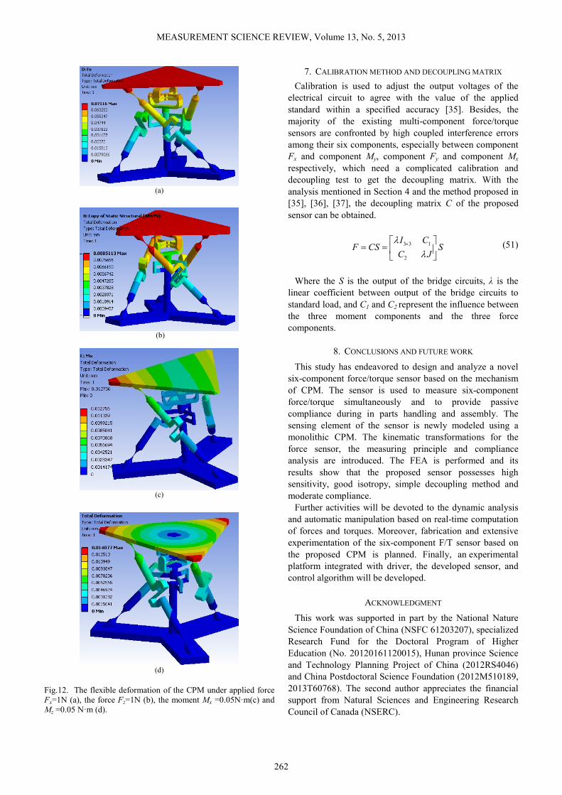
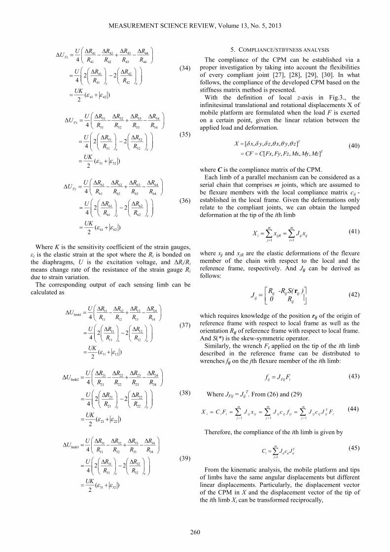
MEASUREMENT SCIENCE REVIEW, Volume 13, No. 5, 2013
262
(a)
(b)
(c)
(d)
Fig.12. The flexible deformation of the CPM under applied force
Fx=1N (a), the force Fz=1N (b), the moment Mx =0.05N·m(c) and
Mz =0.05 N·m (d).
7. CALIBRATION METHOD AND DECOUPLING MATRIX
Calibration is used to adjust the output voltages of the
electrical circuit to agree with the value of the applied
standard within a specified accuracy [35]. Besides, the
majority of the existing multi-component force/torque
sensors are confronted by high coupled interference errors
among their six components, especially between component
Fx and component My, component Fy and component Mx
respectively, which need a complicated calibration and
decoupling test to get the decoupling matrix. With the
analysis mentioned in Section 4 and the method proposed in
[35], [36], [37], the decoupling matrix C of the proposed
sensor can be obtained.
3 3 1
2
I CF CS S
C J
λλ
× = =
(51)
Where the S is the output of the bridge circuits, λ is the
linear coefficient between output of the bridge circuits to
standard load, and C1 and C2 represent the influence between
the three moment components and the three force
components.
8. CONCLUSIONS AND FUTURE WORK
This study has endeavored to design and analyze a novel
six-component force/torque sensor based on the mechanism
of CPM. The sensor is used to measure six-component
force/torque simultaneously and to provide passive
compliance during in parts handling and assembly. The
sensing element of the sensor is newly modeled using a
monolithic CPM. The kinematic transformations for the
force sensor, the measuring principle and compliance
analysis are introduced. The FEA is performed and its
results show that the proposed sensor possesses high
sensitivity, good isotropy, simple decoupling method and
moderate compliance.
Further activities will be devoted to the dynamic analysis
and automatic manipulation based on real-time computation
of forces and torques. Moreover, fabrication and extensive
experimentation of the six-component F/T sensor based on
the proposed CPM is planned. Finally, an experimental
platform integrated with driver, the developed sensor, and
control algorithm will be developed.
ACKNOWLEDGMENT
This work was supported in part by the National Nature
Science Foundation of China (NSFC 61203207), specialized
Research Fund for the Doctoral Program of Higher
Education (No. 20120161120015), Hunan province Science
and Technology Planning Project of China (2012RS4046)
and China Postdoctoral Science Foundation (2012M510189,
2013T60768). The second author appreciates the financial
support from Natural Sciences and Engineering Research
Council of Canada (NSERC).

MEASUREMENT SCIENCE REVIEW, Volume 13, No. 5, 2013
263
REFERENCES
[1] Nakamura, Y., Yoshikawa, T., Futamata, I. (1998).
Design and signal processing of six-axis force sensors.
In Robotics Research : The Fourth International
Symposium. MIT Press, 75-81.
[2] Kim, J.H., Kang, D.I., Shin, H.H., Park, Y.K. (2003).
Design and analysis of a column type multi-
component force/moment sensor. Measurement, 33,
213-219.
[3] Kim, G.S. (2001). The design of a six-component
force/moment sensor and evaluation of its uncertainty.
Measurement Science and Technology, 12 (9), 1445-
1455.
[4] Hashimoto, K. et al. (2013). Overload protection
mechanism for 6-axis force/torque sensor. In Romansy
19 – Robot Design, Dynamics and Control. Springer,
Vol. 544, 383-390.
[5] Liu, S.A., Tzo, H.L. (2002). A novel six-component
force sensor of good measurement isotropy and
sensitivities. Sensors and Actuators A: Physical, 100
(2-3), 223-230.
[6] Liang, Q., Zhang, D., Wang, Y., Coppola, G., Ge, Y.
(2013). PM based multi-component F/T sensors—state
of the art and trends. Robotics and Computer-
Integrated Manufacturing, 29 (4), 1-7.
[7] ATI Industrial Automation. Multi-axis force / torque
sensors.
http://www.ati-ia.com/products/ft/sensors.aspx.
[8] Baki, P., Szekely, G., Kosa, G. (2012). Miniature tri-
axial force sensor for feedback in minimally invasive
surgery. In Biomedical Robotics and Biomechatronics
(BioRob) : 4th IEEE RAS & EMBS International
Conference, 24-27 June 2012. IEEE, 805-810.
[9] Mastinu, G., Gobbi, M., Previati, G. (2011). A new
six-axis load cell. Part I: Design. Experimental
Mechanics, 51 (3), 373-388.
[10] Gailler, A., Reboulet, C. (1983). An isostatic six
component force and torque sensor. In 13th
International Symposium on Industrial Robots and
Robots 7, 17-21 April 1983. Robotics International of
SME.
[11] Dwarakanath, T.A., Bhaumick, T.K., Venkatesh, D.
(1999). Implementation of Stewart platform based
force-torque sensor. In Multisensor Fusion and
Integration for Intelligent Systems (MFI ’99) :
IEEE/SICE/RSJ International Conference, 15-18
August, 1999, 32-37.
[12] Ranganath, R., Nair, P.S., Mruthyunjaya, T.S., Ghosal,
A. (2004). A force-torque sensor based on a Stewart
platform in a near-singular configuration. Mechanism
and Machine Theory, 39 (9), 971-998.
[13] Nguyen, C., Antrazi, S., Zhou, Z. (1991). Analysis and
implementation of a 6 DOF Stewart platform-based
force sensor for passive compliant robotic assembly. In
IEEE Proceedings of Southeastcon ‘91, 7-10 April
1991. IEEE, 880-884.
[14] Dasgupta, B., Reddy, S., Mruthyunjaya, T.S. (1994).
Synthesis of a force–torque sensor based on the
Stewart platform mechanism. In Proceedings of the
National Convention of Industrial Problems in
Machines and Mechanisms, Bangalore, India, 14-23.
[15] Hou, Y., Zeng, D., Yao, J., Kang, K., Lu, L., Zhao, Y.
(2009). Optimal design of a hyperstatic Stewart
platform-based force/torque sensor with genetic
algorithms. Mechatronics, 19 (2), 199-204.
[16] Jia, Z.Y., Lin, S., Liu, W. (2010). Measurement
method of six-axis load sharing based on the Stewart
platform. Measurement, 43 (3), 329-335.
[17] Liu, W., Li, Y.J., Jia, Z.Y., Zhang, J., Qian, M. (2011).
Research on parallel load sharing principle of
piezoelectric six-dimensional heavy force/torque
sensor. Mechanical Systems and Signal Processing, 25
(1), 331-343.
[18] Jin, W.L., Mote, C.D., Jr. (1998). A six-component
silicon micro force sensor. Sensors and Actuators A:
Physical, 65 (2-3), 109-115.
[19] Mei, T., Ge, Y., Chen, Y., Ni, L., Liao, W.H., Xu, Y.,
Li, W.J. (1999). Design and fabrication of an
integrated three-dimensional tactile sensor for space
robotic applications. In Micro Electro Mechanical
Systems (MEMS ’99) : 12th IEEE International
Conference, 17-21 January 1999. IEEE, 112-117.
[20] Brookhuis, R.A., Lammerink, T.S.J., Wiegerink, R.J.,
de Boer, M.J., Elwenspoek, M.C. (2012). 3D force
sensor for biomechanical applications. Sensors and
Actuators A: Physical, 182, 28-33.
[21] Takenawa, S. (2009). A soft three-axis tactile sensor
based on electromagnetic induction. In Mechatronics
2009. ICM 2009 : IEEE International Conference, 14-
17 April 2009. IEEE, 1-6.
[22] Liu, T., Inoue, Y., Shibata, K., Yamasaki, Y.,
Nakahama, M. (2004). A six-dimension parallel force
sensor for human dynamics analysis. In Robotics,
Automation and Mechatronics, 1-3 December 2004.
IEEE, 208-212.
[23] Hirose, S., Yoneda, K. (1990). Development of optical
six-axial force sensor and its signal calibration
considering nonlinear interference. In Robotics and
Automation, 13-18 May 1990. IEEE, 46-53.
[24] Gobbi, M., Previati, G., Guarneri, P., Mastinu, G.
(2011). A new six-axis load cell. Part II: Error
analysis, construction and experimental assessment of
performances. Experimental Mechanics, 51 (3), 389-
399.
[25] Trease, B.P., Moon, Y.M., Kota, S. (2005). Design of
large-displacement compliant joints. ASME Journal of
Mechanical Design, 127, 788-798.
[26] Zhu, Z.H., Meguid, S.A. (2008). Vibration analysis of
a new curved beam element. Journal of Sound and
Vibration, 309 (1), 86-95.
[27] Wu, T., Chen, J., Chang, S. (2008) A six-DOF
prismatic-spherical-spherical parallel compliant
nanopositioner. IEEE Transactions on Ultrasonics
Ferroelectrics and Frequency Control, 55 (12), 2544-
2551.
MEASUREMENT SCIENCE REVIEW, Volume 13, No. 5, 2013
264
[28] Man Bok Hong, Yung-Ho Jo. (2012). Design and
evaluation of 2-DOF compliant forceps with force-
sensing capability for minimally invasive robot
surgery. IEEE Transactions on Robotics, 28 (4), 932-
941.
[29] Dong, W., Sun, L., Du, Z. (2008). Stiffness research
on a high-precision, large-workspace parallel
mechanism with compliant joints. Precision
Engineering, 32 (3), 222-231.
[30] Paros, J.M., Weisbord, L. (1965). How to design
flexure hinges. Machine Design, 37, 151-156.
[31] Smith, S. (2000). Flexures: Elements of Elastic
Mechanisms. New York: Gordon and Breach Science
Publishers.
[32] Boyes, W. (2009). Instrumentation Reference Book,
3rd Edition. Burlington, MA: Elsevier.
[33] Sameer A. Joshi. (2002). A comparative study of two
classes of 3-DOF parallel manipulators. Ph.D.
dissertation, Department of Mechanical Engineering,
University of Maryland, College Park, MD.
[34] Ouyang, P.R. (2005). Hybrid intelligent machine
systems: Design, modeling and control. Ph.D.
dissertation, University of Saskatchewan, Canada.
[35] Liang, Q., Zhang, D., Song, Q., Ge, Y. (2010).
Micromanipulator with integrated force sensor based
on compliant parallel mechanism. In Robotics and
Biomimetics (ROBIO 2010), 14-18 December 2010.
IEEE, 709-714.
[36] Puangmali, P. et al. (2012). Miniature 3-axis distal
force sensor for minimally invasive surgical
palpation. IEEE/ASME Transactions on Mechatronics,
17 (4), 646-656.
[37] Bicchi, A. (1992). A criterion for optimal design of
multi-axis force sensors. Robotics and Autonomous
Systems, 10 (4), 269-286.
Received January 14, 2013.
Accepted October 17, 2013.