day lighting systems 4-1 (1)
TRANSCRIPT

8/2/2019 Day Lighting Systems 4-1 (1)
http://slidepdf.com/reader/full/day-lighting-systems-4-1-1 1/27
This chapter describes the characteristics of advanced daylighting systems, to aid building
professionals in choosing a system. Following this introduction, which summarises the key
elements of the decision-making process for daylighting systems, Section 4.2 consists of a
detailed matrix of daylighting systems classified into two general groups: those with and
without shading. The technical descriptions in Sections 4.3 through 4.14 give details about
the design and application of each system, the physical principles on which it is based, as
well as information about controls, maintenance, costs and energy savings, examples of use,
and simulation or measurement results of the performance associated with each system.
The systems in this chapter represent the large range of advanced daylighting systems
now available to the building profession. Some of these systems are still in the development
or prototype stage and some systems are architectural concepts rather than products (see
Chapter 2).
All of these systems have different characteristics related to the major performance
parameters discussed in Chapter 3. Because these parameters may have different importance
in real-life design cases, it is impossible to develop a unified rating scale or to define a
clear-cut selection method for choosing the best daylighting system in a given situation.
Nonetheless, there are some general strategies for making decisions about using a
daylighting system in a design.
First, a designer should focus on these questions; Chapter 2 discusses in detail the
conditions that will govern the answers:
• Is it useful to apply a daylighting system in my case?
• What kind of problems can I resolve with a daylighting system?
Daylighting Systems 4.
daylighting systems 4
Introduction 4.1.

8/2/2019 Day Lighting Systems 4-1 (1)
http://slidepdf.com/reader/full/day-lighting-systems-4-1-1 2/27
4-2 daylight in buildings
• What benefits could I achieve with a daylighting system?
If the use of a daylighting system appears to be a promising option based on this initial
screening, the next question is:
• Which system should I choose?
This chapter presents the most comprehensive and up-to-date information available,
including measured performance data and expert analysis, to assist designers in answering
that question.
The key parameters to consider in choosing a system are:
• Site daylighting conditions—latitude, cloudiness, obstructions
• Daylighting objectives
• Daylighting strategies implied in the architectural design
• Window scheme and function
• Energy and peak power reduction objectives
• Operational constraints—fixed/operable, maintenance considerations
• Integration constraints—architectural/construction integration
• Economic constraints
It is also important to focus on the major objectives for applying daylighting systems:
• redirecting daylight to under-lit zones
• improving daylighting for task illumination
• improving visual comfort, glare control
• achieving solar shading, thermal control.
It is very important that a reader who wishes to compare the merits of different systems
understand the context of the results given in this chapter. Some measurement results come
from scale-model experiments under simulated light conditions while others come from
full-scale test rooms under real sky conditions at different locations around the world (see
testing facility descriptions given in Appendix 8.4). Because experimental test rooms and
conditions differ so significantly from site to site, we cannot compare the numerical
results from different experimental sites. The general conclusions drawn for each system
are valid, but specific details, such as the absolute magnitude of illumination levels,
cannot be compared among systems tested at dif ferent sites.
The matrix that follows covers two groups of daylighting systems—those with and
without shading.
System Matrix4.2.

8/2/2019 Day Lighting Systems 4-1 (1)
http://slidepdf.com/reader/full/day-lighting-systems-4-1-1 3/27
daylighting systems 4
Daylighting Systems with Shading
Two types of daylighting systems with shading are covered: systems that rely primarily on
diffuse skylight and reject direct sunlight, and systems that use primarily direct sunlight,
sending it onto the ceiling or to locations above eye height.
Shading systems are designed for solar shading as well as daylighting; they may addressother daylighting issues as well, such as protection from glare and redirection of direct or
diffuse daylight. The use of conventional solar shading systems, such as pull-down shades,
often significantly reduces the admission of daylight to a room. To increase daylight
while providing shading, advanced systems have been developed that both protect the area
near the window from direct sunlight and send direct and/or diffuse daylight into the
interior of the room.
Daylighting Systems Without Shading
Daylighting systems without shading are designed primarily to redirect daylight to areas
away from a window or skylight opening. They may or may not block direct sunlight. Thesesystems can be broken down into four categories:
Diffuse Light-Guiding Systems redirect daylight from specific areas of the sky
vault to the interior of the room. Under overcast sky condit ions, the area around
the sky zenith is much brighter than the area close to the horizon. For sites with
tall external obstructions (typical in dense urban environments), the upper
portion of the sky may be the only source of daylight. Light-guiding systems can
improve daylight utilisation in these situations.
Direct Light-Guiding Systems send direct sunlight to the interior of the room
without the secondary effects of glare and overheating.
Light-Scattering or Diffusing Systems are used in skylit or toplit apertures to
produce even daylight distribution. If these systems are used in vertical window
apertures, serious glare will result.
Light Transport Systems collect and transport sunlight over long distances to
the core of a building via fiber-optics or l ight pipes.
Some Notes on the Information in the Matrix
Some systems included in the matrix can fulfil multiple functions and are therefore shown
in more than one category. Light shelves, for instance, redirect both diffuse skylight and
beam sunlight.
Selected column headings from the matrix that are not self-explanatory are described in
detail below:
8/2/2019 Day Lighting Systems 4-1 (1)
http://slidepdf.com/reader/full/day-lighting-systems-4-1-1 4/27
4-4 daylight in buildings
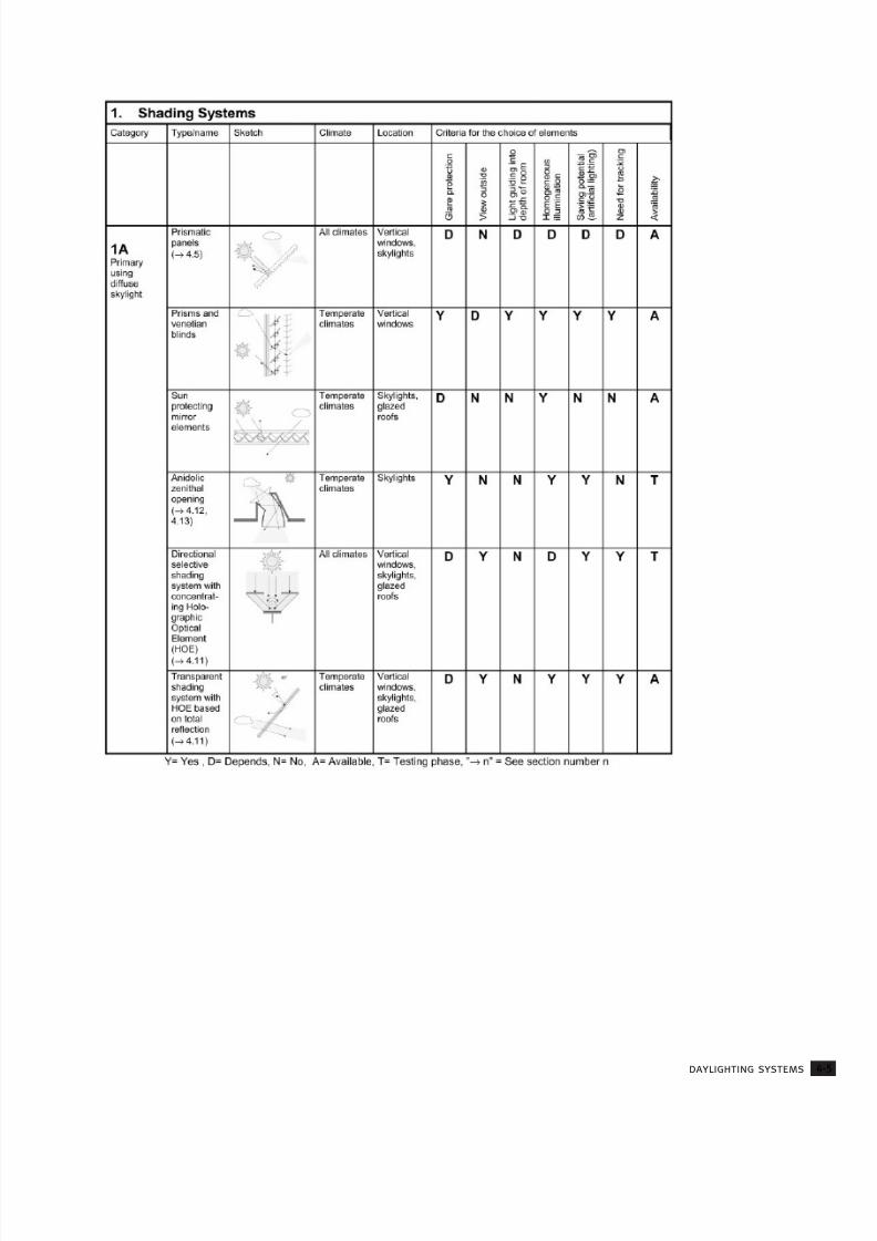
Under the heading “Glare protection,” the following questions were considered: Does the
system prevent glare when viewed directly from the interior, glare from direct sun, and
glare from veiling reflections?
In evaluating “View outside,” the matrix considers the following questions: Does the
system permit a transparent, undistorted view when used in its primary design position?For example, the systems known as anidolic zenithal openings do not permit a clear
unobstructed view to the exterior (they are typically used above a transparent window
which does permit an unobstructed view).
For the column headed “Light-guiding into the depth of the room,” the matrix answers the
question: Does the system achieve light redirection to depths that are greater than
conventional perimeter window systems?
In the column “Homogeneous illumination,” the matrix addresses the question: Does
the system achieve a uniform distribution of daylight throughout a space (walls andceiling)? In assessing “Savings potential (artificial lighting),” the matrix answers the
question: Does the system effectively displace the use of artificial lighting compared to
conventional systems?
In the column headed “Need for tracking,” the matrix answers the question: Are passive
adjustments or mechanical systems needed to track the diurnal or seasonal movement of
the sun throughout the day or year to maintain efficient performance?
“Availability” indicates whether the technology is commercially available (A) or is stil l in
the testing stage (T). Contact information for manufacturers of commercially available
systems is given in Appendix 8.6. Some systems that are labeled as available must be
designed and constructed as an integral part of the building envelope, e.g., light shelves.
For most of the systems included, detailed information is given in the technical descriptions
that follow the matrix. An important exception is light transport systems (group 2D), which
were beyond the scope of this work.
8/2/2019 Day Lighting Systems 4-1 (1)
http://slidepdf.com/reader/full/day-lighting-systems-4-1-1 5/27
daylighting systems 4

8/2/2019 Day Lighting Systems 4-1 (1)
http://slidepdf.com/reader/full/day-lighting-systems-4-1-1 6/27
4-6 daylight in buildings

8/2/2019 Day Lighting Systems 4-1 (1)
http://slidepdf.com/reader/full/day-lighting-systems-4-1-1 7/27
daylighting systems 4

8/2/2019 Day Lighting Systems 4-1 (1)
http://slidepdf.com/reader/full/day-lighting-systems-4-1-1 8/27
4-8 daylight in buildings

8/2/2019 Day Lighting Systems 4-1 (1)
http://slidepdf.com/reader/full/day-lighting-systems-4-1-1 9/27
daylighting systems 4

8/2/2019 Day Lighting Systems 4-1 (1)
http://slidepdf.com/reader/full/day-lighting-systems-4-1-1 10/27
4-10 daylight in buildings
A light shelf is a classic daylighting system, known to the Egyptian
Pharaohs, that is designed to shade and reflect light on its top
surface and to shield direct glare from the sky.
4.3.1. Technical Description
Components
A light shelf is generally a horizontal or nearly horizontal baffle posit ioned inside and/or
outside of the window facade. The light shelf can be an integral part of the facade or
mounted on the building.
Production
Light shelves are not standard, off-the-shelf products.
They must be made to fit the architectural situation in
which they are used.
Location in Window System
A light shelf is usually positioned above eye level. It
divides a window into a view area below and a clerestory
area above. Light shelves sometimes employ advanced
optical systems to redirect light to deep areas of the
building interior. The light shelf is typically positioned to
avoid glare and maintain view outside; its location will
be dictated by the room configuration, ceiling height, and eye level of a person standing
in the space. Generally, the lower the light shelf height, the greater the glare and the amount
of light reflected to the ceiling.
Technical Barriers
An internal light shelf, which redirects and reflects light, will reduce the amount of light
received in the interior relative to a conventional window. Both full-scale and scale model
measurements have shown that windows with internal light shelves produce an overall
reduced daylight factor on the work plane throughout the interior space compared to a
non-shaded window of equal size [Aizlewood 1993, Christoffersen 1995, Littlefair 1996,
Michel 1998]. In some cases, use of an external light shelf makes it possible to increase
the total amount of daylight compared to that provided by traditional windows. An
external light shelf increases exposure to the high luminance area near the sky zenith.
Depending on the light shelf’s geometry, available daylight will be more uniformly
distributed by an external light shelf compared to a non-shaded window of equal size.
Figure 4-3.1:
Semi-transparent
double light shelves
made out of reflective
glass [Littlefair 1996]
Light Shelves4.3.

8/2/2019 Day Lighting Systems 4-1 (1)
http://slidepdf.com/reader/full/day-lighting-systems-4-1-1 11/27
daylighting systems 4
4.3.2. Application
Light shelves affect the architectural and structural design of a building and must be
considered at the beginning of the design phase because they require a relatively high
ceiling in order to function effectively. Light shelves should be designed specifically for
each window orientation, room configuration, and latitude. They can be applied in
climates with significant direct sunlight and are applicable in deep spaces on a south
orientation in the northern hemisphere (north orientation in the southern hemisphere). Light
shelves do not perform as well on east and west orientations and in climates dominated
by overcast sky conditions.
4.3.3. Physical Principles and Characteristics
The orientation, position in the facade (internal, external, or combined), and depth of a
light shelf will always be a compromise between daylight and shading requirements. An
internal light shelf, which redirects and reflects light, will reduce the amount of light received
in the interior. For south-facing rooms (in the northern hemisphere), it is recommended
that the depth of an internal light shelf be roughly equal to the height of the clerestory
window head above the shelf. Moving the light shelf to the exterior creates a parallel
movement of shaded area towards the window facade, which reduces daylight levels near
the window and improves daylight uniformity. The recommended depth of an external light
shelf is roughly equal to its own height above the work plane [Littlefair 1995]. Glazing height
and light shelf depth should be selected based on the specifics of latitude and climate.
At low latitudes, the depth of internal light shelves can be extended to block direct
sunlight coming through the clerestory window at all times (see Figure 4-3.2). At higher
latitudes and with east- or west-facing rooms, a light shelf may let some direct sunlight (low
solar elevation) penetrate the interior, through the space between the light shelf and the
ceiling, resulting in the need for additional shading devices. Increasing the depth of the
shelf will reduce the problem but will also obstruct desired daylight penetration and outside
Figure 4-3.2:
Top section of an
interior and exterior
light shelf with
specular surface, show-
ing the path of sunlight
rays in the winter and
in the
summer. Bottom
section shows how
an upward- or
downward-tilted
reflective light shelf
influences shading
and daylight
reflection. Note
that, in winter, the
light shelf alone does
not adequately
control glare

8/2/2019 Day Lighting Systems 4-1 (1)
http://slidepdf.com/reader/full/day-lighting-systems-4-1-1 12/27
4-12 daylight in buildings
view. Shading the window perimeter by tilting the shelf downward will reduce the amount
of light reflected to the ceiling. Upward tilting will improve penetration of reflected
daylight and reduce shading effects. A horizontal light shelf usually provides the best
compromise between shading requirements and daylight distribution.
The ceiling is an important secondary part of the light shelf system because light isreflected by the light shelf towards the ceiling and then reflected from the ceiling into the
room. The characteristics of the ceiling that affect this process are surface finish, smoothness,
and slope. Although a ceiling with a specular surface will reflect more light into the room,
care should be taken to avoid glare from the ceiling reflections near the light shelf. To avoid
glare, the ceiling finish is usually white diffusing or low-gloss paint.
The penetration of light from a light shelf system depends on the ceiling slope. A gable
style ceiling that slopes upwards from the window towards the centre of the building will
dramatically increase the depth to which light from the light shelf penetrates into the
building. For a flat ceil ing, light from the light shelf is mostly reflected into the space nearthe window, so penetration of light into the room is more modest.
Conventional Light Shelf
A light shelf is usually a fixed, solid system, but some fixed external light shelves can
incorporate slatted baffle systems with reduced upward reflection. The finish of a light shelf
influences the “efficiency” and direction of light redirected from its top to the ceiling. A
matte finish produces diffuse reflection with no directional control, in contrast to a
specular reflection where the angle of incidence is (almost) equal to the angle of reflection.
For a perfectly diffusive surface (Lambertian), only half of the reflected light will be
distributed into the room, but, for an interior light shelf, some of the “lost” light is reflected
towards the interior from the clerestory glass surface. A highly reflective surface (e.g., a
mirror, aluminium, or a polished material) reflects more light to the ceiling than a diffuse
surface but may reflect onto the ceiling an image of any dirt pattern on it [Lam 1986]. A
semi-specular finish for the top of the light shelf may be better. Another possibility is a
reflecting prismatic film to throw l ight further into the room [Littlefair 1996].
Optically Treated Light Shelf
Optically treated light shelves make two significant improvements over conventional light
shelf designs for sunny climates, see Figure 4-3.3: 1) The light shelf geometry is curved and
segmented to passively reflect sunlight for specific solar altitudes, and 2) commercially
available, highly reflective, semi-specular optical films can increase efficiency [Beltrán et al.
1997]. Design objectives are to block direct sun at all times, to increase daylight illuminance
levels up to 10 m from the window wall, to minimise solar heat gains through an optimally
sized window aperture, and to improve daylight uniformity and luminance gradient
throughout the room under variable direct sun conditions. For consistent performance
throughout the year, the optically treated light shelf will project from the exterior wall by
0.1–0.3 m to intercept high summer sun angles. No active adjustment or control is required.

8/2/2019 Day Lighting Systems 4-1 (1)
http://slidepdf.com/reader/full/day-lighting-systems-4-1-1 13/27
daylighting systems 4
The optically treated light shelf design consists of a main lower reflector and a secondary
upper reflector. The lower segmented reflector consists of inclined surfaces that
are finished with a daylight film. The film has linear grooves that reflect sunlight within a
12–15° outgoing angle at normal incidence to the grooves. The segments are inclined to
reflect sun to the ceiling plane up to 10 m from the window wall for noon solstice and
equinox sun angles (south-facing facades in the northern hemisphere). The upper reflector
is placed above the main reflector at the ceiling plane near the window to intercept
incoming low winter sun angles and to reflect these rays to the lower main reflector.
This reflector is surfaced with a highly reflective specular film and may be a small-area
source of glare.
This system has been developed conceptually using scale models. A full-scale modified
skylight prototype has been built and installed in a small office building [Lee et al. 1996].
For vertical window applications, efficient performance of the system requires a room height
greater than 2.5 m from floor to ceiling. It is possible to design and adapt an optically treated
light shelf to existing buildings, but special care should be taken to integrate it with existing
architectural features.
Sun-Tracking Light Shelf
A variable area light reflecting assembly (VALRA) is a tracking light shelf system (see Figure
4-3.4) that reflects light into a building [Howard et al. 1986]. The system uses a reflective
plastic film surface over a tracking roller assembly within a fixed light shelf. This system
extends the projection capabilities of a fixed light shelf so that it functions for all sun angles.
It has not been installed in a building to date. A simpler version of a light shelf that can
be adjusted according to sun position or the sky luminance is the movable (pivotable),
external light shelf (see monitored results from Denmark below).
Figure 4-3.3:
Section of light shelf:
(left) single-level
light shelf, (right)
bi-level light shelf
Figure 4-3.4:
Winter and summer
operation of
the VALRA (Variable
Area Light
Reflecting Assembly)
[Littlefair
1996, Howard
et al. 1986]

8/2/2019 Day Lighting Systems 4-1 (1)
http://slidepdf.com/reader/full/day-lighting-systems-4-1-1 14/27
4.3.4. Control
In general, movable light shelves are more expensive (especially if motorized) than fixed
light shelves, but movable systems are more flexible in control and application. Downward
tilted light shelves shade window perimeters and reduce the amount of light reflected to
the ceiling. Upward-tilted light shelves improve penetration of reflected daylight but
reduce the shading effect of the window perimeter. Exterior-mounted light shelves reduce
cooling loads by providing more shading of direct sun to lower view apertures relative to
what is possible with unobstructed windows with or without interior shades. With interior-
mounted light shelves, there will be an increase in transmitted direct solar radiation
through the non-shaded clerestory window above the light shelf, compared to the light
transmitted by a window that has an interior shading device that covers the full height of
the window. The type of glazing in the clerestory window and lower view window
aperture will also affect solar heat gains.
4.3.5. MaintenanceLight shelves require regular cleaning. An internal shelf collects dust, and an external shelf
can become dirty, collect snow, and provide nesting places for birds or insects. A specular
surface requires maintenance to maintain its reflective properties. Optically treated light
shelves are completely sealed from the interior and exterior environment and protected
from dirt and occupant interference. They require no routine maintenance other than
cleaning of the exterior and interior glass.
4.3.6. Cost and Energy Savings
Reduced light at a window wall can lead to increased use of electric lighting, but increasingthe uniformity of light distribution in the same situation may cause the room to be
perceived as relatively well lit, which may reduce the probability that occupants will switch
on electric lights. The total amount of daylight can be enhanced by using an external light
shelf, depending on the shelf’s geometry and surface treatment. However, most traditional
light shelves do not, in general, produce high levels of illuminance deep inside a space,
so energy savings are modest.
The optically treated light shelf can introduce adequate ambient illuminance for office tasks
in a 5 m to 10 m zone of a deep perimeter space under most sunny conditions with a
relatively small inlet area. It has been found that a room with the optically treated light shelf
can use less total annual electricity for lighting than one with a conventional light shelf.

8/2/2019 Day Lighting Systems 4-1 (1)
http://slidepdf.com/reader/full/day-lighting-systems-4-1-1 15/27
4-22 daylight in buildings
Louvers and blinds are classic daylighting systems that can be applied
for solar shading, to protect against glare and to redirect daylight.
4.4.1. Technical Description
Components
Louvers and blinds are composed of multiple horizontal, vertical, or sloping slats. There
are various kinds of louver and blind systems, some of which make use of highly
sophisticated shapes and surface finishes. Many of these specific types of systems are
described below following a general description of conventional louvers and blinds.
Production
Exterior louvers are usually made of galvanised steel, anodised or painted aluminium, or
plastic (PVC) for high durability and low maintenance. Interior venetian blinds are usually
made from small- or medium-sized PVC or painted aluminium. The slats can be either flat
or curved. Slats are usually evenly spaced at a distance that is smaller than the slat width
so that the slats will overlap when fully closed. Slat size varies with the location of the
blinds: exterior, interior, or between the panes in a double-paned window. Exterior slats
are usually between 50 and 100 mm wide; interior slats are usually 10 to 50 mm wide.
Location in Window System
Louvers or blinds can be located on the exterior or interior of any window or skylight, or
between two panes of glass. Louvers are generally situated on the exterior of the facade;
blinds are fitted inside or between glazing.
Technical Barriers
Depending on slat angle, louvers and blinds partly or completely obstruct directional view
to the outside. Vertical blinds allow a vertical view of the sky dome, and horizontal blinds
reduce the vertical height of the exterior view. An occupant’s perception of view can
sometimes be obstructed by the small-scale structure of slats, which generates visual
confusion as the eye sorts out the outside view from the blind itself. Many louvers and blinds
are therefore designed to be fully or partially retracted.
Under sunny conditions, blinds can produce extremely bright lines along the slats, causing
glare problems. With blinds at a horizontal angle, both direct sunlight and diffuse skylight
can increase window glare due to increased luminance contrast between the slats and
adjacent surfaces. Tilting the blinds upward increases glare as well as visibility of the sky;
tilting the blinds downward provides shading and reduces glare problems. Glossy,
Louvers and Blind Systems4.4.

8/2/2019 Day Lighting Systems 4-1 (1)
http://slidepdf.com/reader/full/day-lighting-systems-4-1-1 16/27
daylighting systems 4
reflective blinds may generate additional glare problems because sun and skylight may be
reflected off the slat surface directly into the field of view. Some of these problems can
be reduced by use of a diffuse slat surface.
4.4.2. ApplicationLouvers and blinds can be used in all orientations and at all latitudes and can be added
to a window system whenever necessary. Exterior blinds affect the architectural and
structural design of a building; interior blinds have less impact. In practise, horizontal louvers
and blinds are generally used on all building orientations, and vertical blinds are
predominantly used on east- and west-facing windows. Advanced designs have different
requirements from conventional blinds.
4.4.3. Physical Principles and Characteristics
Louvers and blinds may obstruct, absorb, reflect and/or transmit solar radiation (diffuseand direct) to a building’s interior. Their effect depends on the position of the sun and their
location (exterior or interior), slat angle, and slat surface reflectance characteristics. Thus,
the optical and thermal properties of a window with louvers or blinds are highly variable.
Horizontal blinds in a horizontal position can receive light from the sun, sky, and ground.
Upward-tilted slats transmit light primarily from the sun and sky, and downward-tilted slats
transmit light primarily from the ground surface. Both louvers and blinds can increase
penetration of daylight from direct sunlight. When skies are overcast, louvers and blinds
promote an even distribution of daylight.
Fixed and Operable Louvers and Blinds
Fixed systems are usually designed for solar shading, and operable systems can be used to
control thermal gains, protect against glare, and redirect daylight. On sunny days, downward-
tilted slats will produce efficient shading of sunlight, but, under cloudy conditions, a fixed
system may cause an unfavourable shading effect that significantly reduces indoor daylight.
Movable systems need to be fully or partially retracted to operate optimally according to
outdoor conditions. Depending on slat angle, slat surface treatment, and the spacing
between slats, both sunlight and skylight may be reflected to the interior.
Translucent Blinds
Translucent blinds transmit a fraction of light when closed. Translucent vertical blinds are
typically 100 mm wide and require little or no cleaning. Translucent blinds can be made
of fabric, plastic, or perforated plastic material (typically offering various levels of light
transmittance). If backlit, the blinds can act as a bright, large-area source of glare.
Light-Directing Louvers
There are many different types of light-directing or reflecting louvers, which generally
consist of an upper surface of highly specular material that sometimes has perforations and

8/2/2019 Day Lighting Systems 4-1 (1)
http://slidepdf.com/reader/full/day-lighting-systems-4-1-1 17/27
4-24 daylight in buildings
concave curvature. Light-directing louvers are usually fitted between glazing and are
typically 10–12 mm in width. These louvers have been designed to reflect the maximum
possible amount of daylight to the ceiling while having a very low brightness at angles
below the horizontal (Figures 4-4.1 and 4-4.2).
The “Fish” systemconsists of fixed
horizontal louvers
with a triangular
section that has
been precisely
aligned by special
connections to
the louver itself [Pohl and Scheiring 1998]. The system, designed only for vertical windows,
is designed to limit glare and redirect diffuse light; additional shading is required (e.g., a
roller blind) if heat gains and admission of sunlight are to be limited. The louvers aredesigned so that light from the upper quarter of the sky is transmitted to the upper
quarter of the room (ceiling). Theoretically, the system without the glazing transmits 60%
of diffuse light for an aluminium surface with 85% reflectance.
The “Okasolar” system, which is also a fixed system, consists of numerous equally spaced,
three-sided, reflective louvers placed inside a double glazed unit. The system reflects light
up towards the ceiling in the winter and has a shading effect in the summer. These blinds
are designed to suit the latitude where they will be used.
4.4.4. Control
Louvers and blinds can be operated either manually or automatically. Automatically
controlled louvers and blinds can increase energy efficiency, if controlled to reduce solar
gain and admit visible daylight during daily and seasonal variations in solar position.
However, automatic systems can produce discomfort in occupants who dislike the feeling
of not having personal control over the system. Manually operated systems are generally
less energy-efficient because occupants may or may not operate them “optimally” (e.g.,
operation may be motivated by glare or view, or systems may be left in position when the
occupant is absent from the room). Research has found that occupant-preferred positions
Figure 4-4.2:
The Okasolar
system consists
of fixed,
equally spaced,
reflective
louvers
Figure 4-4.1:
“Fish” system
consisting
of fixed horizontal
louvers
A B

8/2/2019 Day Lighting Systems 4-1 (1)
http://slidepdf.com/reader/full/day-lighting-systems-4-1-1 18/27
daylighting systems 4
for louvers and blinds are relatively independent of daily, seasonal, and sometimes climatic
conditions. Some studies have found a link between climate and the preferred positions
for louvers and blinds [Rubin et al. 1978, Rea 1984, Inoue et al. 1988].
4.4.5. MaintenanceMaintenance of louvers and blinds can be difficult, especially when they have reflective
slats. Interior slats collect dust; exterior slats can accumulate dirt and snow. Between-pane
systems have an advantage of requiring little cleaning and are not as susceptible to
damage (e.g., bending) as interior and exterior systems.
4.4.6. Cost and Energy Savings
Under sunny conditions, some systems can increase daylight penetration, reduce cooling
loads, and make the variation more uniform between the brighter area near the window
and darker interior zone. Cost and energy savings result from the more efficient use of light without added solar heat gains and cooling loads. For cloudy conditions, louver and blind
systems can be energy-efficient if operated properly because most systems will provide less
interior light than would be admitted by clear, unobstructed glazing. With reflective louver
systems (e.g., those placed in the upper portion of a window to avoid reflected glare),
illuminance levels can be increased under cloudy and sunny conditions when the sun is
near-normal to the window.
4.4.7. Some Examples of Use
• Gartner Office Building, Gundelfingen, Germany: external mirrored blinds• Riehle Office Building, Reutlingen, Germany: reflective louvers/blinds
• NMB Bank, Amsterdam, The Netherlands: reflective louvers
• Swanlea Secondary School, Whitechapel, London, UK: mirrored louvers
• Hooker Chemical Headquarters (offices), Buffalo, New York, USA: movable louvers
• Environmental Office of the Future, Watford, UK: motorised glazed louvers
(Figure 4-4.3 and IEA SHC Task 21 Daylight in Buildings: 15 Case Studies from
Around the World )
• Goetz Building, Wuerzburg, Germany: automated louver blinds
Figure 4-4.3:
Motorised glazed
louvers in the
Environmental Office
of the Future in
Watford, UK

8/2/2019 Day Lighting Systems 4-1 (1)
http://slidepdf.com/reader/full/day-lighting-systems-4-1-1 19/27
4-26 daylight in buildings
4.4.8. Simulations and Measured Results
One type of fixed louvers and five types of venetian blinds were tested.
A. Standard light grey venetian blinds UK
B. Static and automated venetian blinds USA
C. Translucent venetian blinds UK
D. Fixed louvers–Fish system Austria
E. Inverted semi-silvered venetian blinds UK
F. Inverted semi-silvered translucent venetian blinds Denmark
A. Standard, Light Grey Venetian Blinds (United Kingdom)
The Building Research Establishment, United Kingdom (UK), tested conventional 38-mm
venetian blinds with a light grey finish. The blind system was monitored at three slat angle
positions (fully closed, horizontal, and 45° downward tilted) in a south-facing mock-up
office. The reference room was identical to the test room, but had unshaded, clear glazing.

8/2/2019 Day Lighting Systems 4-1 (1)
http://slidepdf.com/reader/full/day-lighting-systems-4-1-1 20/27
4-38 daylight in buildings
Prismatic panels are thin, planar, sawtooth devices made of clear
acrylic that are used in temperate climates to redirect or refract
daylight. When used as a shading system, they refract direct sunlight
but transmit diffuse skylight. They can be applied in many different
ways, in fixed or sun-tracking arrangements, to facades and skylights.
4.5.1. Technical Description
Components
A linear prismatic panel consists of an array of acrylic prisms with one surface of each prism
forming a plane surface known as the prism backing. There are two refracting angles. Very
often these prismatic systems are inserted in a double-glazed unit to eliminate maintenance.
Prismatic Panels4.5.

8/2/2019 Day Lighting Systems 4-1 (1)
http://slidepdf.com/reader/full/day-lighting-systems-4-1-1 21/27
daylighting systems 4
Production
Currently, two different manufacturing
processes are used to make prismatic panels:
Injection moulding. Prismatic panels are
produced from acrylic polymer in fourdifferent configurations (different refracting
angles). Some panels are partially coated
with an aluminium film with high specular
reflectance on one surface of each prism.
Specialised etching. This etching process
produces prisms that are spaced less than a
millimeter apart. The resulting acrylic film is
lightweight yet still has good optical
properties. This film can be applied on theinside of a double-glazed unit.
Location in Window System
Prismatic panels are used in fixed and
movable configurations. Depending on the
daylighting strategy being used, they can
be positioned in the window pane (fixed
configuration) on the exterior and/or interior side. The panels offer a transparent but
distorted view to the outside. An extra view window will usually be needed unless the panel
can open to allow a view.
Prismatic panels have two very different functions: a) solar shading, and b) redirection of
daylight. Their location in relation to the facade or the roof is very dependent on the specific
application.
Technical Barriers
If prismatic panels are used as sun-shading devices in a fixed configuration, additional
components are needed to prevent colour dispersion. These could include, for example,
an etched sheet of glass (slightly diffusing) behind the system.
If used for redirecting sunlight, currently available prismatic panel designs may redirect some
sunlight downward, causing glare. Computer analysis shows that for a vertical, fixed
prismatic panel, some downward sunlight is inevitable at some times of the year. With
correct profile and seasonal tilting, these downward beams can be avoided, however.
Historically, the effect of prismatic panels on daylight has been well known. There are
patents on this technology dating from the beginning of the 20th century. However,
Figure 4-5.2:
Cross-section of a
linear prismatic panel
and visualisation of
the light redirection
achieved by the panel
Figure 4-5.1:
Four types
of commercially
available
prismatic panels

8/2/2019 Day Lighting Systems 4-1 (1)
http://slidepdf.com/reader/full/day-lighting-systems-4-1-1 22/27
4-40 daylight in buildings
production was a significant barrier in the past. With the advent of acrylic polymer, it
became possible for the first time to produce very precise panels. In addition, covering
single surfaces of a prism with reflective coatings has expanded the possibilities of
prismatic systems. Still, cost is an important barrier to the panels’ wider use.
The panels’ high coefficient of expansion usually requires that they be designed to allowfor thermal expansion. Since acrylic burns, fire regulations must be checked when
prismatic panels are used.
4.5.2. Application
As a light-directing system, prismatic panels can be used to guide diffuse daylight or
sunlight.
Diffuse Daylight
Prismatic panels are normally used in the vertical plane of the facade to redirect light from the outside sky to the upper half
of the inside room, usually the ceiling. Simultaneously,
the panels reduce the brightness of the window. With this
profile, the panels operate best as an anti-glare system with
a simultaneous light-directing function. For sunny facades,
however, additional sun shading is necessary in front of
the panels.
Sunlight
Prismatic panels can also be used to direct sunlight into a room.
To prevent glare and also colour dispersion, the correct profile
and a seasonal tilting of the panels are essential. See Section 4.5.8
for test room studies at the University of Sydney, Australia.
Fixed Sun-Shading System
This application is usually found in glazed roofs. The prismatic
structure is designed according to the movement of the sun, and
the panels are integrated into a double-glazed unit. See Section
4.5.8 for measurements made at Bartenbach LichtLabor, Austria.
Moveable Sun-Shading System
For this application, prismatic panels are used in louver form.
They are placed in front of or behind double glazing, in a
vertical or horizontal arrangement (a double glazed unit is no
longer necessary). This application will control glare from the
sun but not the sky; in other words, it acts only as a sun-
shading device.

8/2/2019 Day Lighting Systems 4-1 (1)
http://slidepdf.com/reader/full/day-lighting-systems-4-1-1 23/27
daylighting systems 4
4.5.3. Physical Principles and Characteristics
The main function of light-directing prismatic glazing is to achieve deep penetration of
natural light. The prismatic panel uses both reflection and refraction to enable the
controlled use of daylight in buildings. The system can be designed to reflect light coming
from a certain range of angles while transmitt ing light coming from other angles. Refraction
and total internal reflection (based on the critical angle of the material) can be used to
change the direction of transmitted light rays. The fractions of reflected and refracted light
depend on the angle of incidence, the indices of refraction, and the state of polarisation
of the incident light.
For deep penetration of sunlight, a prismatic panel must accommodate a wide range of solar
altitudes. The refracted light should emerge at an angle less than 15° above the horizontal
to obtain maximum penetration without creating descending rays of sunlight that create
glare. The panel’s performance is therefore determined by an appropriate configuration
of the refracting angles. A specific configuration for the prismatic profile is usually required
for different geometric and geographic situations, to achieve high illuminance levels at theback of a room. In addition, a good surface texture with a high reflectivity is required for
the ceiling, especially in the area near the window and for approximately one-third of the
ceiling depth.
4.5.4. Control
When prismatic panels are applied as a movable sun-shading system, one-axis automatic
tracking of the panels according to the movement of the sun is generally required. For many
light-redirection applications, only seasonal adjustments are needed.
4.5.5. Maintenance
Prismatic panels inside a double-glazed unit do not require any maintenance other than
the normal washing of the exterior and interior glazing surfaces. If the panels are exposed,
they must be very carefully cleaned so as not to damage the optical surfaces.
4.5.6. Cost and Energy Savings
Costs for a prismatic panel alone are in the range of 200 euros (for high-volume production)
Figure 4-5.3:
Behaviour of
direct and diffuse
components of
daylight in a fixed
prismatic sun-shading
device (left) and
in a movable
prismatic sun-shading
device (right). The
phenomenon of
total internal
reflection
is used to reflect
the sun’s rays

8/2/2019 Day Lighting Systems 4-1 (1)
http://slidepdf.com/reader/full/day-lighting-systems-4-1-1 24/27
daylighting systems 4
The laser-cut panel is a daylight-redirecting system produced by
making laser cuts in a thin panel made of clear acrylic material.
4.6.1. Technical Description
Components
A laser-cut panel is a thin panel that has
been divided by laser cutting into an array
of rectangular elements. The surface of
each laser cut becomes a small internal
mirror that deflects light passing through
the panel. The principal characteristics of
a laser-cut panel are: (a) a very high
proportion of light deflected through
a large angle (>120°), (b) maintenance of
Laser-Cut Panel 4.6.
Figure 4-6.1:
View through a
laser-cut panel

8/2/2019 Day Lighting Systems 4-1 (1)
http://slidepdf.com/reader/full/day-lighting-systems-4-1-1 25/27
4-50 daylight in buildings
view through the panel (see Figure 4-6.1), and (c) a flexible manufacturing method
suitable for small or large quantities.
Light is deflected in each element of the panel by refraction, then by total internal
reflection, and again by refraction (see Figure 4-6.2). Because all deflections are in the same
direction, the deflection is highly efficient. The panels are usually fixed inside glazing units,but they may also be used as external glazing if the cut surface is protected by lamination
between glass sheets. Normally the panels are cut at an angle perpendicular to the
surface, but it is possible to make the cuts at a different angle for added control over the
direction of the deflected light [Edmonds 1993, Reppel and Edmonds 1998].
Production
Panels are produced by laser cutting a sheet
of clear acrylic (PMMA). They are designed
to include a solid periphery and support
sections. The laser cutter is programmed with the design.
Laser cuts are usually made right through the panels because this method requires less
control of cutting speed and laser power than other approaches. For this reason, it is
necessary to design the panel so that solid regions 10-20 mm wide are left to support the
cut sections. For example, a panel 1000 mm x 600 mm that has laser cuts right through a
6 mm thick acrylic panel requires a 20-30-mm-wide solid periphery and two vertical solid
support sections that are 10-20 mm wide. It is possible to cut only partway through the
panel, e.g., 75% depth. However, a solid periphery is still necessary for structural strength.
Location in Window System
Laser-cut panels may be used in fixed and movable
arrangements within a window system. There is
view through the panels. However, even though
laser-cut panels maintain high transparency with
limited distortion of the view out, they should
mainly be used for daylight apertures and not for
view windows, or at least not when occupants are
close to view windows. Because the panels redirect downward incoming light in an upward
direction, it is desirable that they be installed above eye level in windows to avoid glare.
The panels may also be used in louver arrangements or, if produced in narrow widths, as
venetian style arrangements. As movable louvers, the system rejects sunlight when the
panels are in the open louver position (see Figure 4-6.3, above left) and redirects light when
the panels are in the closed louver position (see Figure 4-6.3, above right). Whether in
louver or venetian form, laser-cut panel panels may be adjusted to the open, summer
position to reject light or to the closed, winter position to admit light.
Figure 4-6.2:
Showing the
fraction “f” of light
deflected in a
prism and an array
of prisms. The fraction
f is given as a
function of
incidence angle in
figure 4.6.5
figure 4-6.3:
In louver or venetian
form, laser-cut panels
may be adjusted to the
open, summer position
to reject light or to
the closed, winter
position to admit light

8/2/2019 Day Lighting Systems 4-1 (1)
http://slidepdf.com/reader/full/day-lighting-systems-4-1-1 26/27
daylighting systems 4
Technical Barriers
The main technical barrier to laser-cut panels is their cost, approximately 100 euros per
square metre. At present, the panels are designed and cut to suit the size and shape of
specific windows. They can also be produced in a laminated sheet that can be cut to size,
but this process has not yet been established commercially.
4.6.2. Application
Laser-cut light-deflecting panels can be applied as:
• a fixed sun-shading system for windows, as shown in Figure 4-6.4,
• a light-redirecting system (fixed or movable), as shown in Figure 4-6.8, or
• a sun-shading/light-directing system for windows (in louvered or venetian form)
as shown in principle in Figure 4-6.3.
4.6.3. Physical Principles and Characteristics
Fixed Light-Directing System
A laser-cut panel with a cut spacing to cut depth ratio (D/W) of 0.7 that is fixed vertically
in a window will deflect nearly all light incident from above 45° and transmit most light
incident from below 20° (see Figure 4-6.5). Thus, a high fraction of light is deflected by
the panel onto the ceiling which then acts as a secondary source of diffuse reflected light
in a similar way to a light shelf.
Light-Directing System in Windows
A vertical laser-cut panel strongly deflects light incident from higher elevations, >30°, while
transmitting light at near normal incidence with little disturbance, thus maintaining view.
Figure 4-6.5 shows the fraction of light deflected versus elevation angle of incident light
on a vertical laser-cut panel. The panel has very low glare because the deflected light is
directed strongly upwards while the undeflected light continues in the same downward
direction as the incident light. The scattered light is low because no rounded surfaces are
Figure 4-6.4:
Laser-cut panels that
are 20 mm wide panels
can be installed
venetian style
between two glass
panes to form a
double-glazed
window. This angle-
selective form of
window rejects a high
proportion of
incident sunlight
while maintaining
good viewing
characteristics. (See
Figure 4-6.7 for
irradiance versus
time of day for an
east-facing window at
the latitude of Paris,
48.8°N.)

8/2/2019 Day Lighting Systems 4-1 (1)
http://slidepdf.com/reader/full/day-lighting-systems-4-1-1 27/27
produced in the manufacturing process. Nevertheless, it is desirable to use laser-cut
panels in the upper half of windows.
Sun-Shading System in Windows
If an array of narrow panels is mounted horizontally in a window, i.e., with the face of
the panels horizontal, then sunlight from higher elevations is deflected back to the outside.
Thus, this system is very effective for excluding sunlight while being entirely open for
viewing (See Figures 4-6.6 and 4-6.7).
Figure 4-6.5:
The fraction of light
deflected versus
elevation of incident
light for a vertical
laser-cut panel with
three different cut
spacing (D) to cut
depth (W) ratios
Figure 4-6.6:
Horizontal laser-cut
panels form an
angle-selective
window that
deflects light
to the outside
Figure 4-6.7:
The irradiance
through an
east-facing
angle- selective
window at the
latitude of
Paris (48.8°N)