data & specifications - maersk fluid · pdf filethe particle size and count for rt-flex...
TRANSCRIPT
DATA &
SPECIFICATIONS
Next opportunity
Preventive action To ensure trouble-free operation of Wärtsilä 2-stroke engines, it is important to follow the recommendations about lubricating oils stated in this bulletin.
Validity This Technical Bulletin remains valid from the date of issue until further notice.
Note This Data & Specifications bulletin Issue 5 supersedes Data & Specifications bulletin RT-138, Issue 4, dated 22.02.2014. Reasons:
Appendix 1 to RT-138 is updated.
The particle size and count for RT-flex and W-X engines has been updated.
The Figure 1: Piston Under Side (PUS) drain oil analysis interpretation has been updated.
The Figure 2: Relationship between fuel sulphur content and cylinder oil BN has been updated.
Wärtsilä Switzerland Ltd. Tel (24h): +41 52 262 80 10
PO Box 414
CH-8401 Winterthur [email protected]
Issue 5, 25 January 2016
Lubricating oils
Information to all Owners and Operators of Wärtsilä 2-stroke engines.
RT-138 Wärtsilä 2-stroke
Technical Services

DATA & SPECIFICATIONS RT-138, Issue 5, Page 2 / 18
Contents
Page
1 Introduction 2
2 System oil 2
3 Cylinder lubricating oil 10
4 Turbocharger oil 17
5 Turning gear oil 17
6 Lubricant for flywheel and pinion gear teeth 17
7 Environmentally acceptable lubricants 17
8 Appendices 17
9 Contacts 18
1 Introduction
NOTE:
This Data & Specifications bulletin Issue 5 supersedes Data & Specifications bulletin
RT-138, Issue 4, dated 22 December 2014. Reasons:
Appendix 1 to RT-138 is updated.
The particle size and count for RT-flex and W-X engines have been updated.
Figure 1 and Figure 2 have been updated.
2 System oil
The system oil provides lubrication for the bearings, the running parts of the engine and
the crosshead assembly. In addition, system oil is used as hydraulic fluid in the servo
oil system of the engine and also cools the pistons.
System oil requirements:
An additive-type crankcase oil of the SAE 30 viscosity grade must be used as
system oil.
It must have a minimum BN of 5.0 mgKOH/g and detergent properties.
It must meet load carrying performance in the FZG1 gear machine test method
A/8, 3/90 according to ISO 14635-1, Failure Load Stage (FLS) 11 as a minimum.
Good thermal stability, anti-corrosion and anti-foam properties and good
demulsifying performance are further requirements.
NOTE:
Validated lubricating oils for Wärtsilä two-stroke engines are given in:
Appendix 1 “Validated cylinder and system oils”.
For other or new lubricants contact Wärtsilä. The contact details are given in
Chapter 9 “Contacts”.
1 The FZG gear machines located at the FZG Institute, Munich/Germany, shall be the reference test apparatus and will be used in the event of any uncertainty about test repeatability and reproducibility

DATA & SPECIFICATIONS RT-138, Issue 5, Page 3 / 18
2.1 Oil care
2.1.1 System oil
To keep the lubricating oil in good condition for a long period, effective oil treatment is
necessary. This is achieved by using a self-cleaning, centrifugal separator working as
purifier in by-pass, by circulating the oil from the oil tank through the separator. The
purifier throughput shall be set according to the recommendation of the separator
manufacturer. However it is recommended to maintain the oil temperature at 95 °C for
this treatment unless it is advised otherwise by the separator supplier.
Solid contaminants (dirt) and water must be removed from the oil as completely as
possible. There is always the risk that water can enter the system and cause corrosive
attack on engine parts, particularly with sea water. Water contamination can also lead
to bacterial contamination of the oil resulting in loss of lubrication capability and heavy
corrosion of the system. Good maintenance is the most effective precaution to keep
water out of the oil. The water content of the lubricating oil must not exceed 0.2% by
mass over an extended period of time. If higher water contamination is observed,
special measures such as intensified treatment in the separator or in a renovating tank
must be considered.
2.1.2 Servo oil system of RT-flex, W-X82 and W-X92 engines
In order to prolong the lifetime of the sliding parts, fine filtered oil is used in this system.
Fine filtered oil is branched off from the system oil and flows through an additional
automatic filter, which flushes back to the system oil, which flushes back to the system
oil. The filter mesh size is according to the particular engine specifications.
The function of the flushing process and the low differential pressure shall be
monitored during operation of the automatic filter; see documentation of the automatic
filter manufacturer.
The bypass filter element can be used temporarily for inspecting and cleaning the
regular elements, or if these elements have to be removed for any reason.
2.2 Attention limits for selected system oil parameters
The condition of the lubricating system oil charge can be assessed by analysing
selected parameters. With regular checks deterioration can be detected at an early
stage and remedial procedures must be taken.
The following guide limits must not be exceeded for a long period in service; these are
the oil alert limits:
Table 1: Alert limits of system oil parameters for RT-flex and W-X engines
Parameter Unit Limit Test method
Viscosity at 40 °C mm2/s [cSt] max. 140 ASTM D 445
Flash point (PMCC) °C min. 200 ASTM D 92
Total insolubles % m/m max. 0.70 ASTM D 893b
Base Number (BN) mgKOH/g max. 12 ASTM D 2896
Water content % m/m max. 0.20 ASTM D 95 or ASTM D 1744
FZG gear machine test Failure load stage min. 9 ISO 14635-1 A8, 3/90
DATA & SPECIFICATIONS RT-138, Issue 5, Page 4 / 18
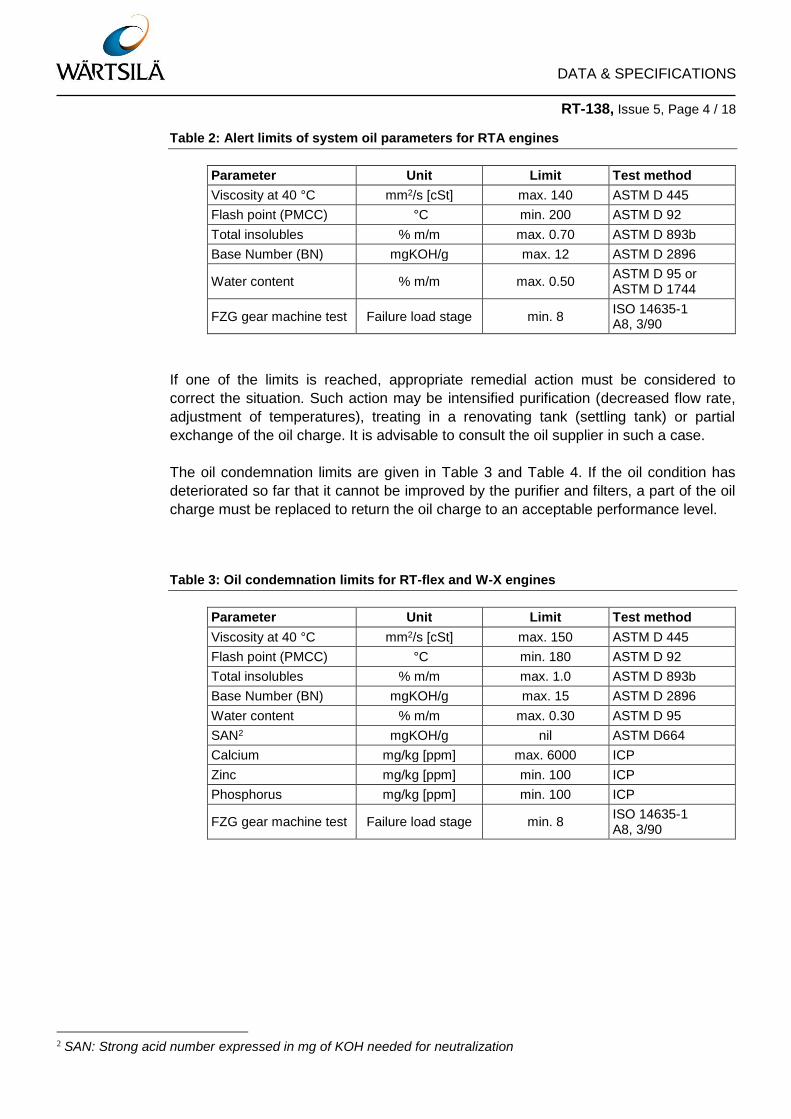
Table 2: Alert limits of system oil parameters for RTA engines
Parameter Unit Limit Test method
Viscosity at 40 °C mm2/s [cSt] max. 140 ASTM D 445
Flash point (PMCC) °C min. 200 ASTM D 92
Total insolubles % m/m max. 0.70 ASTM D 893b
Base Number (BN) mgKOH/g max. 12 ASTM D 2896
Water content % m/m max. 0.50 ASTM D 95 or ASTM D 1744
FZG gear machine test Failure load stage min. 8 ISO 14635-1 A8, 3/90
If one of the limits is reached, appropriate remedial action must be considered to
correct the situation. Such action may be intensified purification (decreased flow rate,
adjustment of temperatures), treating in a renovating tank (settling tank) or partial
exchange of the oil charge. It is advisable to consult the oil supplier in such a case.
The oil condemnation limits are given in Table 3 and Table 4. If the oil condition has
deteriorated so far that it cannot be improved by the purifier and filters, a part of the oil
charge must be replaced to return the oil charge to an acceptable performance level.
Table 3: Oil condemnation limits for RT-flex and W-X engines
Parameter Unit Limit Test method
Viscosity at 40 °C mm2/s [cSt] max. 150 ASTM D 445
Flash point (PMCC) °C min. 180 ASTM D 92
Total insolubles % m/m max. 1.0 ASTM D 893b
Base Number (BN) mgKOH/g max. 15 ASTM D 2896
Water content % m/m max. 0.30 ASTM D 95
SAN2 mgKOH/g nil ASTM D664
Calcium mg/kg [ppm] max. 6000 ICP
Zinc mg/kg [ppm] min. 100 ICP
Phosphorus mg/kg [ppm] min. 100 ICP
FZG gear machine test Failure load stage min. 8 ISO 14635-1 A8, 3/90
2 SAN: Strong acid number expressed in mg of KOH needed for neutralization

DATA & SPECIFICATIONS RT-138, Issue 5, Page 5 / 18
Table 4: Oil condemnation limits for RTA and older 2-stroke engines
Parameter Unit Limit Test method
Viscosity at 40 °C mm2/s [cSt] max. 160 ASTM D 445
Flash point (PMCC) °C min. 190 ASTM D 92
Total insolubles % m/m max. 2.0 ASTM D 893b
Base Number (BN) mgKOH/g max. 30 ASTM D 2896
Water content % m/m max. 0.50 ASTM D 95
SAN mgKOH/g nil ASTM D664
Calcium mg/kg [ppm] max. 6000 ICP
Zinc mg/kg [ppm] min. 100 ICP
Phosphorus mg/kg [ppm] min. 100 ICP
FZG gear machine test Failure load stage min. 7 ISO 14635-1 A8, 3/90
These limits are set out as guidance. The quality condition of the oil in circulation,
however, cannot be fully assessed by a single parameter. Other oil parameters must
be used in context to be able to find the cause of the problem and the appropriate
remedy for correction.
If the Base Number (BN) of the system oil rises sharply, do a check of the condition of
the piston rod gland box and the piston rod.
A certain consumption and replenishment of system oil is required to keep the system
oil in good condition.
If there is a significant decrease of the flash point below the recommended values
given above, you must replenish the oil charge.
The replenishment prevents an increase in system oil BN. A small increase in BN is
often an indication that the system oil consumption is low.
The open cup type of flash point determination (e.g. COC) should be used to decide if
a partial or complete change of oil charge is necessary.
The closed cup flash point determination (e.g. PMCC) can be used to monitor the
system oil condition, but not for oil change.
The FZ gear machine performance test (method A/8, 3/90, ISO 14635-1 of the oil
charge) is very important if a new gear wheel, camshaft or fuel pump follower is
polished or replaced. This gives protection against scuffing during the running-in of
these components. If the system oil was used for more than a year, measure the FZG
performance of the oil. This will show if the performance of the oil is satisfactory for
new or polished gear wheels, camshaft or fuel pump follower.
Regular on board checks of BN and water content must be done in order to obtain an
early indication of oil degradation.

DATA & SPECIFICATIONS RT-138, Issue 5, Page 6 / 18
2.3 Particle size and count for RT-flex and W-X engines
Particle size analysis can give useful data about the wear in an engine. Abrasive
particles in the oil can cause wear, thus the requirements must be closely followed. The
requirements for particle size refer only to the oil in RT-flex and W-X hydraulic oil
systems. These systems operate the exhaust valves, fuel systems and cylinder
lubrication systems.
The NAS 1638 and SAE AS 4059 particle count requirements were previously
specified as per Table 5, Table 6 and Table 7, NAS 1638 method has been
superseded by the ISO 4406 method (see Table 8). However, SAE AS 4059 should still
be consulted for particles larger than 21 µm. NAS data is only provided for reference
purposes.
Table 5: Recommended limits in NAS classes for RT-flex, W-X82 and W-X92 engines
(Engines with Servo Oil filter)
Particle size (µm or microns)
5–15 15–25 25–50 50–100 100–150
Cleanliness system oil 12 11 10 8 5
Lubricating oil separator
Cleanliness servo oil 12 11 8 5 0
Servo oil filter
Table 6: Recommended limits in NAS classes for W-X35, W-X40, W-X62 and W-X72
engines (Engines without Servo Oil filter)
Particle size (µm or microns)
5–15 15–25 25–50 50–100 100–150
Lubricating oil 12 11 9 7 5
Lubricating oil separator
DATA & SPECIFICATIONS RT-138, Issue 5, Page 7 / 18
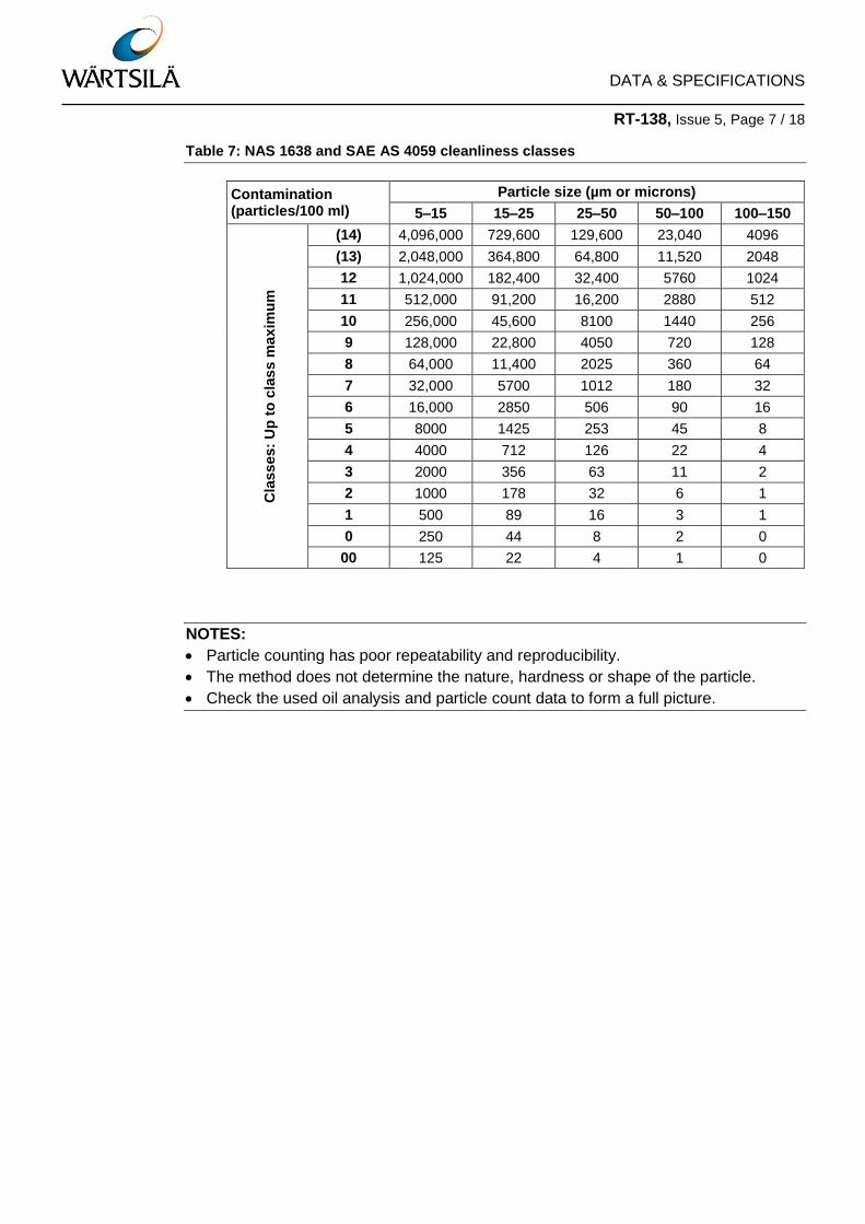
Table 7: NAS 1638 and SAE AS 4059 cleanliness classes
Contamination (particles/100 ml)
Particle size (µm or microns)
5–15 15–25 25–50 50–100 100–150
Cla
ss
es:
Up
to
cla
ss m
ax
imu
m
(14) 4,096,000 729,600 129,600 23,040 4096
(13) 2,048,000 364,800 64,800 11,520 2048
12 1,024,000 182,400 32,400 5760 1024
11 512,000 91,200 16,200 2880 512
10 256,000 45,600 8100 1440 256
9 128,000 22,800 4050 720 128
8 64,000 11,400 2025 360 64
7 32,000 5700 1012 180 32
6 16,000 2850 506 90 16
5 8000 1425 253 45 8
4 4000 712 126 22 4
3 2000 356 63 11 2
2 1000 178 32 6 1
1 500 89 16 3 1
0 250 44 8 2 0
00 125 22 4 1 0
NOTES:
Particle counting has poor repeatability and reproducibility.
The method does not determine the nature, hardness or shape of the particle.
Check the used oil analysis and particle count data to form a full picture.

DATA & SPECIFICATIONS RT-138, Issue 5, Page 8 / 18
Table 8: ISO 4406 particle count and size classes
Number of particles per 100 ml
More than Up to and including Class
250,000,000 — <28
130,000,000 250,000,000 28
64,000,000 130,000,000 27
32,000,000 64,000,000 26
16,000,000 32,000,000 25
8,000,000 16,000,000 24
4,000,000 8,000,000 23
2,000,000 4,000,000 22
1,000,000 2,000,000 21
500,000 1,000,000 20
250,000 500,000 19
130,000 250,000 18
64,000 130,000 17
32,000 64,000 16
16,000 32,000 15
8000 16,000 14
4000 8000 13
2000 4000 12
1000 2000 11
500 1000 10
250 500 9
130 250 8
64 130 7
32 64 6
16 32 5
8 16 4
4 8 3
2 4 2
1 2 1
0 1 0
The ISO 4406 particle count system operates with 3 size classes based on a 100 ml oil
sample, which are:
R4 = Number of particles equal to or larger than 4 µm
R6 = Number of particles equal to or larger than 6 µm
R14 = Number of particles equal to or larger than 14 µm
> 6 µm max.
> 14 µm max.

DATA & SPECIFICATIONS RT-138, Issue 5, Page 9 / 18
2.3.1 Recommended limits for ISO 4406 particle count
The requirement for 100 ml of oil sample is therefore:
ISO 4406 --/20/17 maximum
in the servo oil system after the automatic fine filter of RT-flex, W-X82 and W-X92
engines
in the lube oil system of W-X35, W-X40, WX62 and W-X72 engines after the main
lube oil filter on plant side
Which means:
ATTENTION:
ISO 4406 is valid only for particles up to 21 µm. For particles with sizes above 21 µm,
SAE particle count requirements must be followed.
2.3.2 Particle counts in the servo oil of RT-flex and W-X engines
If the particle count is higher than specified, do a check of the coarse and fine filters.
This will make sure that all filter elements, gaskets and seals are serviceable. If the
high particle count continues and the filters are in serviceable condition, there is
probably an area of the engine that is worn too much. This will cause too many
particles. Too many particles can go into the system oil if the piston rod gland boxes do
not seal correctly. This causes used cylinder oil to go into the system oil. The purifier
also removes particles. You must make sure that the purifier operates at the correct
temperature in accordance with the manufacturer's instructions. Also, make sure that
the flow rate is adjusted to get the best performance.
A maximum of 130,000 particles equal or larger than > 14 µm
A maximum of 1,000,000 particles equal or larger than > 6 µm
No requirement to count particles equal or larger than > 4 µm

DATA & SPECIFICATIONS RT-138, Issue 5, Page 10 / 18
2.4 System oil samples
At regular intervals (e.g. approximately every 300 operation hours), it is recommended
that a sample of the system oil shall be taken and sent to a laboratory for analysis. The
analysis must include ISO 4406 particle counting for samples taken after the filter,
before the oil goes into the engine main oil gallery or the servo system.
With the oil pump running and the engine oil at operating temperature, drain a small
quantity of oil from a cock in the lubricating system to flush out any dirt accumulated in
this cock and rinse the clean sample container with some oil.
Subsequently take an oil sample in the sample bottle marked with the following
information for the laboratory:
Ship’s name or name of plant
Engine type
Engine serial number
Date of sampling
Operating hours of oil and of engine
Sampling point location
Oil brand and type
3 Cylinder lubricating oil
A high-alkaline cylinder lubricating oil of the SAE 50 viscosity grade with a minimum
kinematic viscosity of 18.5 cSt at 100°C is recommended. However, cylinder oils of the
viscosity grades SAE 40 and SAE 60 can be used under certain circumstances. The
alkalinity of the oil is indicated by its Base Number (BN) measured in mgKOH/g
according to method ASTM D 2896. The base number of cylinder lubricants is not an
index for detergency, but a direct measure of alkalinity.
To choose the appropriate alkalinity of the cylinder lubrication oil, monitor regularly the
piston underside drain oil. In particular, the residual BN of the drain oil should be
measured as an indicator of correct cylinder lubrication. The residual BN of the drain oil
is such a meaningful parameter, because it is influenced by the sulphur content of the
fuel, cylinder lubrication feed rate, engine tuning and operating conditions. Within the
safe operating range (shown in Figure 1) the lubrication oil feed rate and alkalinity can
be optimized. During operation, the feed rate must not exceed the upper limit of 1.2
g/kWh. Fuels with a sulphur content in the range of 0.1% m/m to 0.5 % m/m using
cylinder oils with BN15 and BN25 are excluded. For fuels with a sulphur content in the
given range, see Figure 2. If a feed rate of 1.2 g/kWh is not sufficient to keep within the
safe operating range, the BN of the cylinder oil must be increased. For more details
about the procedure, see Technical Bulletin RT-161, “Cylinder Lubrication”.
For the cylinder lubricating oil selection and feed rate optimization process, Figure 2
provides starting points of cylinder lubrication oils at a given sulphur content fuel.
DATA & SPECIFICATIONS RT-138, Issue 5, Page 11 / 18
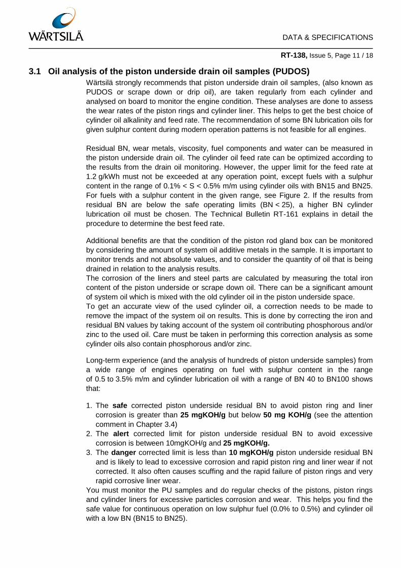
3.1 Oil analysis of the piston underside drain oil samples (PUDOS)
Wärtsilä strongly recommends that piston underside drain oil samples, (also known as
PUDOS or scrape down or drip oil), are taken regularly from each cylinder and
analysed on board to monitor the engine condition. These analyses are done to assess
the wear rates of the piston rings and cylinder liner. This helps to get the best choice of
cylinder oil alkalinity and feed rate. The recommendation of some BN lubrication oils for
given sulphur content during modern operation patterns is not feasible for all engines.
Residual BN, wear metals, viscosity, fuel components and water can be measured in
the piston underside drain oil. The cylinder oil feed rate can be optimized according to
the results from the drain oil monitoring. However, the upper limit for the feed rate at
1.2 g/kWh must not be exceeded at any operation point, except fuels with a sulphur
content in the range of 0.1% < S < 0.5% m/m using cylinder oils with BN15 and BN25.
For fuels with a sulphur content in the given range, see Figure 2. If the results from
residual BN are below the safe operating limits (BN < 25), a higher BN cylinder
lubrication oil must be chosen. The Technical Bulletin RT-161 explains in detail the
procedure to determine the best feed rate.
Additional benefits are that the condition of the piston rod gland box can be monitored
by considering the amount of system oil additive metals in the sample. It is important to
monitor trends and not absolute values, and to consider the quantity of oil that is being
drained in relation to the analysis results.
The corrosion of the liners and steel parts are calculated by measuring the total iron
content of the piston underside or scrape down oil. There can be a significant amount
of system oil which is mixed with the old cylinder oil in the piston underside space.
To get an accurate view of the used cylinder oil, a correction needs to be made to
remove the impact of the system oil on results. This is done by correcting the iron and
residual BN values by taking account of the system oil contributing phosphorous and/or
zinc to the used oil. Care must be taken in performing this correction analysis as some
cylinder oils also contain phosphorous and/or zinc.
Long-term experience (and the analysis of hundreds of piston underside samples) from
a wide range of engines operating on fuel with sulphur content in the range
of 0.5 to 3.5% m/m and cylinder lubrication oil with a range of BN 40 to BN100 shows
that:
1. The safe corrected piston underside residual BN to avoid piston ring and liner
corrosion is greater than 25 mgKOH/g but below 50 mg KOH/g (see the attention
comment in Chapter 3.4)
2. The alert corrected limit for piston underside residual BN to avoid excessive
corrosion is between 10mgKOH/g and 25 mgKOH/g.
3. The danger corrected limit is less than 10 mgKOH/g piston underside residual BN
and is likely to lead to excessive corrosion and rapid piston ring and liner wear if not
corrected. It also often causes scuffing and the rapid failure of piston rings and very
rapid corrosive liner wear.
You must monitor the PU samples and do regular checks of the pistons, piston rings
and cylinder liners for excessive particles corrosion and wear. This helps you find the
safe value for continuous operation on low sulphur fuel (0.0% to 0.5%) and cylinder oil
with a low BN (BN15 to BN25).

DATA & SPECIFICATIONS RT-138, Issue 5, Page 12 / 18
Fuel sulphur in the range 0.5 < Sulphur % < 3.5 m/m and cylinder oil with 40 < BN < 100
Figure 1: Piston Underside (PUS) drain oil analysis interpretation
NOTE:
There are smooth transitions between the various areas as shown in Figure 1.
Figure 1 shows where engines fitted with chrome ceramic piston rings and fully honed
liners must be operated in regard to piston underside total oil iron content and residual
BN. The cylinder oil BN and/or lubricant feed rate must be changed to ensure that there
is no excessive corrosive or magnetic iron in the piston underside oil.
The chromium content of the PUS oil is also an important indicator of corrosion or wear
in the engine, when chrome ceramic piston rings are fitted. Chromium values of less
than 25 mg/kg show that there is little corrosion and wear in the engine. Values above
approximately 25 mg/kg indicate that corrosion and/or wear are occurring, which may
reduce piston ring and liner life. The chrome content of the piston underside oil must
not exceed 25 mg/kg for long periods of time.
ATTENTION:
Engines fitted with cast iron or non-chrome ceramic rings usually have significantly
higher total iron levels than those stated above under normal operating conditions.
DATA & SPECIFICATIONS RT-138, Issue 5, Page 13 / 18
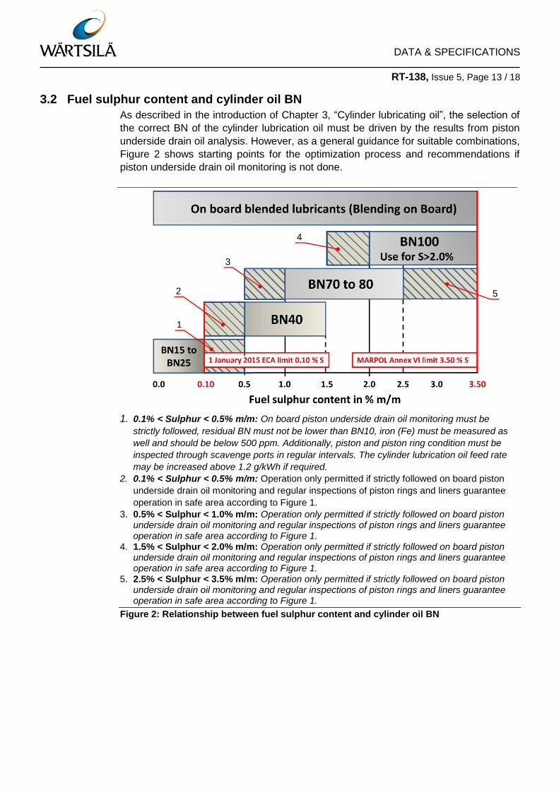
3.2 Fuel sulphur content and cylinder oil BN
As described in the introduction of Chapter 3, “Cylinder lubricating oil”, the selection of
the correct BN of the cylinder lubrication oil must be driven by the results from piston
underside drain oil analysis. However, as a general guidance for suitable combinations,
Figure 2 shows starting points for the optimization process and recommendations if
piston underside drain oil monitoring is not done.
3.3
1. 0.1% < Sulphur < 0.5% m/m: On board piston underside drain oil monitoring must be
strictly followed, residual BN must not be lower than BN10, iron (Fe) must be measured as
well and should be below 500 ppm. Additionally, piston and piston ring condition must be
inspected through scavenge ports in regular intervals. The cylinder lubrication oil feed rate
may be increased above 1.2 g/kWh if required.
2. 0.1% < Sulphur < 0.5% m/m: Operation only permitted if strictly followed on board piston
underside drain oil monitoring and regular inspections of piston rings and liners guarantee
operation in safe area according to Figure 1.
3. 0.5% < Sulphur < 1.0% m/m: Operation only permitted if strictly followed on board piston underside drain oil monitoring and regular inspections of piston rings and liners guarantee operation in safe area according to Figure 1.
4. 1.5% < Sulphur < 2.0% m/m: Operation only permitted if strictly followed on board piston underside drain oil monitoring and regular inspections of piston rings and liners guarantee operation in safe area according to Figure 1.
5. 2.5% < Sulphur < 3.5% m/m: Operation only permitted if strictly followed on board piston underside drain oil monitoring and regular inspections of piston rings and liners guarantee operation in safe area according to Figure 1.
Figure 2: Relationship between fuel sulphur content and cylinder oil BN
4
5
1
2
3

DATA & SPECIFICATIONS RT-138, Issue 5, Page 14 / 18
NOTES:
Since 1 January 2015, only fuel with a maximum of 0.1% m/m sulphur must be used
in ECAs (SOx scrubbers can be used to reduce the effective exhaust sulphur
content).
Use BN100 cylinder oil if fuel sulphur content is above 2.5% m/m and no piston
underside drain oil monitoring is done.
Monitor the residual BN of the PU drain oil to select the applicable BN of the
lubrication oil and to get the best feed rate. At the same time, do regular inspections
of the piston rings and cylinder liners to prevent corrosion and particles on the top
land. The set feed rate should never exceed the upper limit of 1.2 g/kWh except
fuels with a sulphur content in the range of 0.1% m/m to 0.5% m/m using cylinder
oils with BN15 and BN25. For fuels with a sulphur content in this range, see
Figure 2. If the feed rate is at the value given, and the results from piston underside
drain oil monitoring indicates a rest BN < 25, the BN of the cylinder oil must be
increased. For more information, see Technical Bulletin RT-161.
Cylinder oils of excessively high BN for the fuel sulphur cause excessive accumulation
of particles on the piston crown. Monitor carefully the particles on the piston crown
through the scavenge ports. These particles can break down the lubricant film and
cause the piston, piston rings and cylinder liner wear.
NOTE:
The BN 40 products can be used safely with heavy fuel oil with a sulphur content in the
range 0.5% to 1.5% m/m. The feed rate must be changed in relation to the remaining
BN measured in the piston underside drain oil or scrape down samples.
Intermediate BN cylinder oils (BN 50 to BN 60) are still available. Only use these
cylinder oils if the performance is monitored regularly from the PU drain oil analysis.
Also, do regular inspections of piston rings and cylinder liners through the scavenge air
ports. The inspections must be done during the adjustment of lubricating oil feed rate to
operate the engine in the safe area shown in Figure 1. Incorrectly adjusted piston
underside BN can lead to excessive corrosive wear and scuffing. For the limits and
recommendations, refer to the previous Chapter 3.1. If the residual PU drain oil is
below the limit for safe operation (even at a feed rate of 1.2 g/kWh), a higher feed rate
setting is not necessary. However, a cylinder oil with a higher BN must be chosen.
DATA & SPECIFICATIONS RT-138, Issue 5, Page 15 / 18
ATTENTION:
Use only the cylinder and system oils given in Appendix 1. The oil supplier assumes all
responsibility for the performance of the lubricating oils in service of all Wärtsilä 2-
stroke engines to the exclusion of any liability of any Wärtsilä company belonging to the
Wärtsilä group. The oil supplier along with other possible manufacturers and
distributors of the products in question shall indemnify, compensate and hold harmless
Wärtsilä and companies belonging to the Wärtsilä group from and against any claims,
damages and losses caused by the lubricating oils in question.
To avoid problems with fuel sulphur content, it is good practice to keep enough of the
previous bunker. This can be used until an analysis of the sulphur content of the new
bunker has been received. The Bunker Delivery Note (BDN) and bunker analysis can
show inaccuracy in measuring the sulphur content and possible different HFO
composition. The sulphur content used to set the correct feed rate must be the higher
value of the BDN or the bunker analysis to ensure safe operation.
3.4 General recommendations
Service experience has shown that when operating below 60% CMCR, the engine
corrosion behaviour can vary significantly. Therefore Wärtsilä recommends the
following:
Wartsila recommends a cylinder lubricating oil of BN 100 if the engine is to
operate at continuous low load (i.e. for more than 24 hours at below 60% CMCR)
and with HFO that has a sulphur content above 2.5% m/m. The feed rate cannot
be adjusted sufficiently to compensate for the lower alkalinity unless the PU
drain oil results inspections of piston rings and cylinder liners are different. The
maximum allowed feed rate for stable operation on other than 100 BN, 15 BN and
25 BN lubricants is 1.2 g/kWh. If the results from the piston underside drain oil
monitoring would require higher feed rates for 25 < BN < 100 cylinder oil, a
change to 100 BN cylinder oil must be done. For BN ≤ 25 see Figure 2 see
Technical Bulletin RT-161 for details. BN 100 lubricants are available from most of
the lubrication oil suppliers (see Data & Specification bulletin RT-138, Appendix 1). A
high BN lubricant adapted to the piston running and corrosion condition of the engine
can also be achieved by using the Blending on Board package. This product allows the
flexible on board production of a “fit for purpose” cylinder lubricant down to 30 BN to
overcome corrosion or to operate with low sulphur residual fuels.
It is important to monitor the corrected residual BN on a regular basis and to ensure
that the value is met as shown in Figure 1.
An on-board monitoring programme should at least permit the assessment of the
residual BN from piston underside drain oil. The measurement of total iron and
chromium in the piston underside oil is also recommended. A sudden increase of the
values of iron or chromium would indicate the occurrence of significant cold corrosion
and appropriate countermeasures should be applied (see also Technical Bulletin
RT-161, entitled “Cylinder lubrication” for more information).
DATA & SPECIFICATIONS RT-138, Issue 5, Page 16 / 18
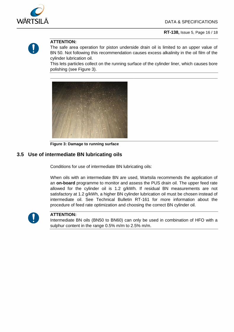
ATTENTION:
The safe area operation for piston underside drain oil is limited to an upper value of
BN 50. Not following this recommendation causes excess alkalinity in the oil film of the
cylinder lubrication oil.
This lets particles collect on the running surface of the cylinder liner, which causes bore
polishing (see Figure 3).
Figure 3: Damage to running surface
3.5 Use of intermediate BN lubricating oils
Conditions for use of intermediate BN lubricating oils:
When oils with an intermediate BN are used, Wartsila recommends the application of
an on-board programme to monitor and assess the PUS drain oil. The upper feed rate
allowed for the cylinder oil is 1.2 g/kWh. If residual BN measurements are not
satisfactory at 1.2 g/kWh, a higher BN cylinder lubrication oil must be chosen instead of
intermediate oil. See Technical Bulletin RT-161 for more information about the
procedure of feed rate optimization and choosing the correct BN cylinder oil.
ATTENTION:
Intermediate BN oils (BN50 to BN60) can only be used in combination of HFO with a
sulphur content in the range 0.5% m/m to 2.5% m/m.

DATA & SPECIFICATIONS RT-138, Issue 5, Page 17 / 18
4 Turbocharger oil
To select and maintain the turbocharger lubricating oil, the recommendations given in
the turbocharger supplier’s instruction manual must be obeyed.
The turbocharger oil is normally system oil, or turbine oil depending on the
turbocharger supplier’s recommendations.
5 Turning gear oil
For the choice and maintenance of the lubricant, the recommendations given in the
turning gear supplier’s instruction manual must be obeyed.
6 Lubricant for flywheel and pinion gear teeth
The selection and application of the lubricant must be in compliance with the
specification published in the Maintenance Manual Group 3, Chapter 3206–1 “Turning
gear” and the recommendations by the engine manufacturer. In addition, the lubricant
suppliers are given in:
Appendix 2 “Lubricants for flywheel and pinion gear teeth”.
7 Environmentally acceptable lubricants
Environmentally Acceptable Lubricants (EAL) are currently required for ships operating
in USA waters, and this area may be extended in future. These lubricants which are
required for all ‘oil to sea interfaces’ which include stern tubes, thrusters, rudders,
stabilisers, variable pitch propellers, underwater ropes and machinery and underwater
transmissions are made with base oils and additives which are significantly different to
those used for system and cylinder oil. Consequently EAL’s should not be mixed into
system or cylinder oils where they are to be used in engine applications. Even small
contaminations of EAL (depending on base oil quality) into system and cylinder oil can
lead to elastomer compatibility, water emulsification and high temperature deposit
formation issues.
8 Appendices
1. Validated Cylinder and System Oils.
2. Lubricants for Flywheel and Pinion Gear Teeth.
DATA & SPECIFICATIONS RT-138, Issue 5, Page 18 / 18
9 Contacts
9.1 How to contact Wärtsilä
For questions about the content of this Data & Specifications bulletin, or if you need
Wärtsilä assistance, services, spare parts and/or tools, please contact your nearest
Wärtsilä representative.
If you do not have the contact details at hand, please follow the link “Contact us” – “24h
Services” on the Wärtsilä webpage:
www.wartsila.com
9.2 Contact details in case of emergency
9.2.1 Operational support
For questions concerning operational issues, please send your enquiry to:
or phone 24hrs support: +41 52 262 80 10.
9.2.2 Field service
If you need Wärtsilä Field Service, please send your enquiry to:
or phone 24hrs support: +41 79 255 68 80.
9.2.3 Spare parts
If you need Wärtsilä spare parts and/or tools, please contact your nearest Wärtsilä
representative or your key account manager.
© 2016 Wärtsilä Switzerland Ltd. – All rights reserved No part of this publication may be reproduced or copied in any form or by any means (electronic, mechanical, graphic, photocopying, recording, taping or other information retrieval systems) without the prior written permission of the copyright holder. Wärtsilä Switzerland Ltd. makes no representation, warranty (express or implied) in this publication and assumes no responsibility for the correctness, errors or omissions for information contained herein. Information in this publication is subject to change without notice. Unless otherwise expressly set forth, no recommendation contained in this document or any of its appendices is to be construed as provided due to a defect of the product, but merely as an improvement of the product and/or the maintenance procedures relating thereto. Any actions by the owner/operator as a result of the recommendations are not covered under any warranty provided by Wärtsilä and such actions will thus be at the owners/operators own cost and expense. NO LIABILITY WHETHER DIRECT, INDIRECT, SPECIAL, INCIDENTAL OR CONSEQUENTIAL, IS ASSUMED WITH RESPECT TO THE INFORMATION CONTAINED HEREIN. THIS PUBLICATION IS CONFIDENTIAL AND INTENDED FOR INFORMATION
PURPOSES ONLY.