data center achieving enterprise san performance with … · data center achieving enterprise san...
TRANSCRIPT

www.brocade.com
Data Center achieving enterprise San Performance with the Brocade DCX Backbone
WHITE PAPER
A best-in-class architecture enables optimum performance, flexibility, and reliability for enterprise data center networks.
2
the Brocade® DCX® Backbone is the industry’s highest-performing enterprise-class platform for Storage area networks (Sans). With its intelligent sixth-generation aSICs and new hardware and software capabilities, the Brocade DCX provides a reliable foundation for fully connected, multiprotocol San fabrics, FICOn solutions, and MetaSans capable of supporting thousands of servers and storage devices.
the Brocade DCX Backbone also provides industry-leading power and cooling efficiency, helping to reduce the Total Cost of Ownership (TCO), as well as helping to reduce overall Opex.
this paper details the architecture advantages of the Brocade DCX Backbone and describes how It organizations can leverage the performance capabilities, modular flexibility, and “five-nines” (99.999 percent) reliability of this SAN platform to achieve specific business requirements.
OverviewIn January 2008, Brocade introduced the Brocade DCX Backbone (see Figure 1), the first platform in the industry to provide 8 Gigabits per second (Gbps) Fibre Channel (FC) capabilities. With the release of Fabric OS® (FOS) 6.0 at the same time, the Brocade DCX Backbone added 8 Gbps Fibre Channel and FICON performance for data-intensive storage applications.
In January 2009, the Brocade DCX-4S (see Figure 2) was added to the backbone family, and the Brocade DCX has become a key component in thousands of data centers around the world. New Fibre Channel over Ethernet (FCoE) and SAN extension blades were introduced in September 2009. In June 2010, Brocade launched the industry’s first and only 8 Gbps 64-port blade.
Although this paper focuses on the Brocade DCX, some information is provided for the Brocade DCX-4X Backbone, notably in the section on Inter-Chassis Link (ICL) configuration. For more details on these two backbone platforms, see the Brocade DCX Backbone Family Data Sheet on www.brocade.com.

3
Compared to competitive offerings, the Brocade DCX Backbone is the industry’s fastest and most advanced SAN backbone, providing numerous advantages:
Scales non-disruptively from 16 to as many as 512 concurrently active 4 or 8 Gbps full-• duplex ports in a single domain (open systems)
Scales non-disruptively from 16 to as many as 256 concurrently active 4 or 8 Gbps full-• duplex ports in a single domain (FICON)
Enables simultaneous uncongested switching on all ports as long as simple best practices • are followed
Can provide 4.6 Terabits per second (Tbps) (Brocade DCX) or 2.3 Tbps (Brocade DCX-4S) • utilizing 8 Gbps blades, Inter-Chassis Links (ICLs), and Local Switching.
In addition to providing the highest levels of performance, the Brocade DCX Backbone features a modular, high-availability architecture that supports mission-critical environments. Moreover, the platform’s industry-leading power and cooling efficiency helps reduce ownership costs while maximizing rack density.
The Brocade DCX Backbone uses just 6 watts AC per port and 0.7 watts per Gbps at its maximum 8 Gbps 512-port configuration. The Brocade DCX-4S uses just 6.7 watts AC per port and 0.8 watts per Gbps at its maximum 8 Gbps 256-port configuration. Both are twice as efficient as its their predecessors and up to six times more efficient than competitive products. This efficiency not only reduces data center power bills—it reduces cooling requirements and minimizes or eliminates the need for data center infrastructure upgrades, such as new Power Distribution Units (PDUs), power circuits, and larger Heating, Ventilation, and Air Conditioning (HVAC) units. In addition, the highly integrated architecture uses fewer active electric components boarding the chassis, which improves key reliability metrics such as Mean Time Between Failure (MTBF).
The Brocade DCX Backbone leverages a highly flexible multiprotocol architecture, supporting Fibre Channel, Fibre Connectivity (FICON), Fibre Channel over Ethernet, Fibre Channel over IP (FCIP), IP over Fibre Channel (IPFC), and Data Center Bridging (DCB) IT organizations can also easily mix FC port blades with advanced functionality blades for FCoE server I/O convergence, SAN encryption, and SAN extension to build an infrastructure that optimizes functionality, price, and performance. And ease of setup enables data center administrators to quickly maximize its performance and availability.
This paper describes the internal architecture of Brocade DCX Backbones and how best to leverage their industry-leading performance and blade flexibility to meet business requirements.
How is Fibre Channel Bandwidth Measured?Fibre Channel is a lossless, low- latency, full-duplex network protocol, meaning that data can be transmitted and received simultaneously. The name of a specific Fibre Channel standard, for example “8 Gbps FC,” refers to how fast an application payload can move in one direction. This is called “data rate.” Vendors sometimes state data rates followed by the words “full duplex”, for example “8 Gbps full duplex”, although it is not necessary when referring to Fibre Channel speeds. The term “aggregate data rate” is the sum of the application payloads moving in each direction (full duplex) and is equal to twice the data rate.
Figure 1. Brocade DCX (left) and Brocade DCX-4S (right).

4
BrOCade dCX aSiC FeatureSThe Brocade DCX Backbone Control Routers (CR8s) feature Brocade “Condor 2” ASICs, each capable of switching at 640 Gbps. Each Brocade Condor 2 ASIC has 40 x 8 Gbps ports, which can be combined into trunk groups of multiple sizes. The Brocade DCX architecture leverages the same Fibre Channel protocols as the front-end ports, enabling back-end ports to avoid latency due to protocol conversion overhead.
When a frame enters the ASIC, the destination address is read from the header, which enables routing decisions to be made before the entire frame has been received. This is known within the industry as Cut-Through Routing, which means that a frame can begin transmission out of the correct destination port on the ASIC even before the frame has finished entering the ingress port. Local latency on the same ASIC is 0.7 µs and blade-to-blade latency is 2.1 µs. As a result, the Brocade DCX has the lowest switching latency and highest throughput of any Fibre Channel backbone platform in the industry.
Each Condor 2 (8 Gbps) ASICs on a port blade can act as an independent switching engine to provide Local Switching between port groups in addition to switching across the backplane. Local Switching traffic does not cross the backplane, nor consume any slot bandwidth. This enables every port on high-density blades to communicate at full 8 Gbps. That is just 700 ns—at least 25 times faster than the next-fastest SAN enterprise platform on the market. On the 16-, 32-, and 64-port blades, Local Switching is performed within 16-port groups. On 48-port blades, Local Switching is performed within 24-port groups. Only Brocade offers an
enterprise architecture that can make these types of switching decisions at the port level, enabling Local Switching and the ability to deliver up to 4.6 Tbps (Brocade DCX) and 2.0 Tbps (Brocade DCX-4S) of aggregate bandwidth per backbone.
To support long-distance configurations, 8 Gbps blades have Condor 2 ASICs that provide 2,048 buffer-to-buffer credits per 16-port group on 16-, 32-, and 64-port blades, and per 24-port group on 48-port blades.
Condor 2 ASICs also enable Brocade Inter-Switch Link (ISL) Trunking with up to 64 Gbps full-duplex, frame-level trunks (up to 8 x 8 Gbps links in a trunk) and Dynamic Path Selection (DPS) for exchange-level routing between individual ISLs or ISL Trunking groups. Exchange-based DPS automatically optimizes fabric-wide performance by automatically routing data to the most efficient available path in the fabric. DPS augments ISL Trunking to provide more effective load balancing in certain configurations, such as routing data between multiple trunk groups. Up to 8 trunks can be balanced to achieve a total throughput of 512 Gbps. Furthermore, Brocade has significantly improved frame-level Trunking through a “masterless link” in a trunk group. If an ISL trunk link ever fails, the ISL trunk seamlessly reforms with the remaining links, enabling higher overall data availability.
Preventing frame loss during an event such as the addition or removal of an ISL while the fabric is active is a critical customer requirement. Lossless Dynamic Load Sharing and DPS enable optimal utilization of ISLs by performing traffic rebalancing operations during fabric events such as E_Port up/down, F_Port down, and so on. Typically, when a port goes down or comes back up, frames may be dropped or arrive out of order or traffic imbalance may occur. Brocade’s Lossless DLS/DPS architecture rebalances traffic at the frame and exchange level delivering in-order traffic without dropping frames, thus preventing application timeouts or SCSI retries.
Unlike competitive offerings, frames that are switched within port groups are always capable of full port speed.

5
BrOCade dCX PLatFOrM arCHiteCtureIn the Brocade DCX, each port blade has Condor 2 ASICs that expose some ports for user connectivity and some ports to the control processors’ core switching ASICs via the backplane. The backbone uses a multi-stage ASIC layout analogous to a “fat-tree” core/edge topology. The fat-tree layout is symmetrical, that is, all ports have equal access to all other ports. The platform can switch frames locally if the destination port is on the same ASIC as the source. This is an important feature for high-density environments, because it allows blades that are oversubscribed when switching between blade ASICs to achieve full, uncongested performance when switching on the same ASIC. No other backbone offers Local Switching—with competing offerings, traffic must traverse the crossbar ASIC and backplane even when traveling to a neighboring port—a function that significantly degrades performance.
The flexible Brocade DCX architecture uses a wide variety of blades for increasing port density, multiprotocol capabilities, and fabric-based applications. Data center administrators can easily mix the blades in the Brocade DCX to address specific business requirements and optimize cost/performance ratios. The following blades are currently available (as of mid-2010).
Blade Name description introduced with
CP8 - Control Processor Provides service activities and manageability of the backbone
FOS 6.0
CR8 - Core Switching 1,024 Gbps per CR8 ICL ports on every CR8 blade turned on via an optional license
FOS 6.0
FC8-16 16 ports, 8 Gbps FC blade FOS 6.0
FC8-32 32 ports, 8 Gbps FC blade FOS 6.1
FC8-48 48 ports, 8 Gbps FC blade FOS 6.1
FC8-64 64 ports, 8 Gbps FC blade FOS 6.4
FCOE10-24 24 ports, 10 Gbps FCoE/DCB blade FOS 6.3
FS8-18 Encryption Blade
16 ports, 8 Gbps, line-speed encryption of data-at-rest
FOS 6.1.1_enc
FX8-24 Extension Blade
24 ports, 12 x 8 Gbps FC ports, 10 x 1 Gigabit Ethernet (GbE) ports, and two optional 10 GbE ports for long-distance extension of FCIP blade
FOS 6.3
FC10-6 6 ports, 10 Gbps FC blade FOS 5.3
FA4-18 Fabric Application Blade
18 ports, 4 Gbps FC application blade FOS 5.3
6
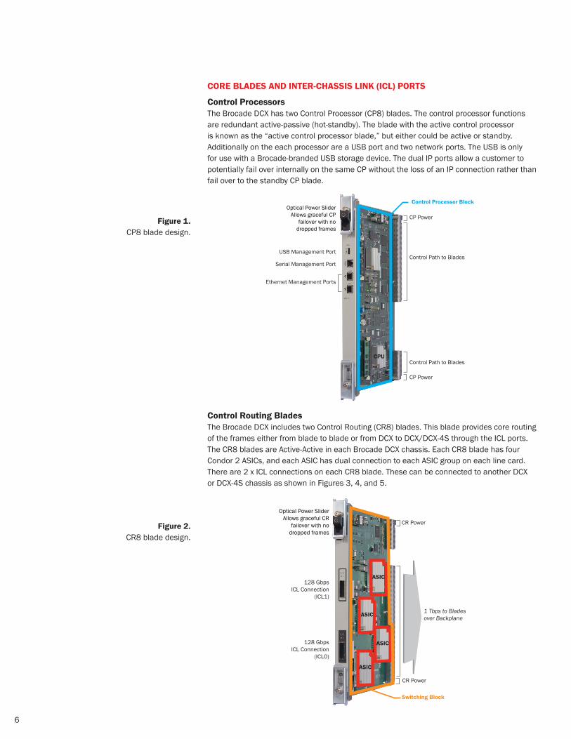
COre BLadeS aNd iNter-CHaSSiS LiNk (iCL) POrtS
Control Processors The Brocade DCX has two Control Processor (CP8) blades. The control processor functions are redundant active-passive (hot-standby). The blade with the active control processor is known as the “active control processor blade,” but either could be active or standby. Additionally on the each processor are a USB port and two network ports. The USB is only for use with a Brocade-branded USB storage device. The dual IP ports allow a customer to potentially fail over internally on the same CP without the loss of an IP connection rather than fail over to the standby CP blade.
Control routing BladesThe Brocade DCX includes two Control Routing (CR8) blades. This blade provides core routing of the frames either from blade to blade or from DCX to DCX/DCX-4S through the ICL ports. The CR8 blades are Active-Active in each Brocade DCX chassis. Each CR8 blade has four Condor 2 ASICs, and each ASIC has dual connection to each ASIC group on each line card. There are 2 x ICL connections on each CR8 blade. These can be connected to another DCX or DCX-4S chassis as shown in Figures 3, 4, and 5.
Figure 1. CP8 blade design.
Optical Power SliderAllows graceful CP
failover with nodropped frames
Control Path to Blades
CP Power
Control Processor Block
USB Management Port
Serial Management Port
Ethernet Management Ports
CP Power
Control Path to Blades CPU
Optical Power SliderAllows graceful CR
failover with nodropped frames
CR Power
1 Tbps to Bladesover Backplane
CR Power
ASIC
ASIC
ASIC
ASIC
128 GbpsICL Connection
(ICL1)
128 GbpsICL Connection
(ICL0)
Switching Block
Figure 2. CR8 blade design.
7
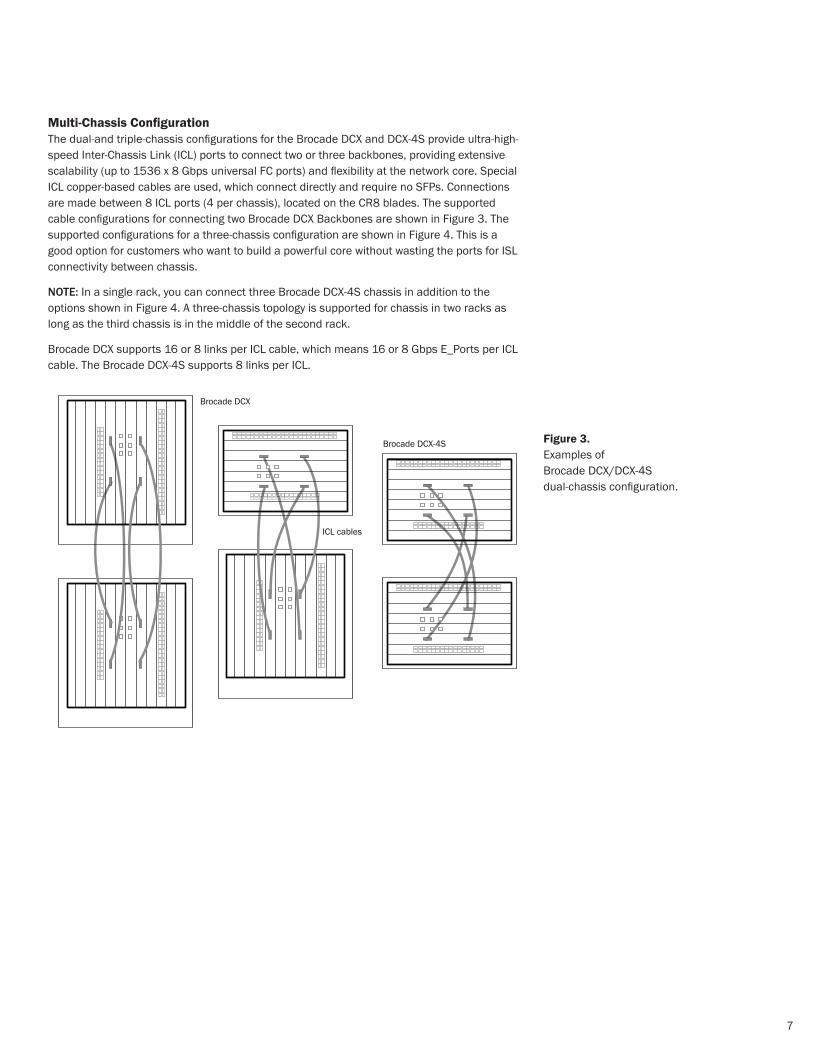
Multi-Chassis ConfigurationThe dual-and triple-chassis configurations for the Brocade DCX and DCX-4S provide ultra-high-speed Inter-Chassis Link (ICL) ports to connect two or three backbones, providing extensive scalability (up to 1536 x 8 Gbps universal FC ports) and flexibility at the network core. Special ICL copper-based cables are used, which connect directly and require no SFPs. Connections are made between 8 ICL ports (4 per chassis), located on the CR8 blades. The supported cable configurations for connecting two Brocade DCX Backbones are shown in Figure 3. The supported configurations for a three-chassis configuration are shown in Figure 4. This is a good option for customers who want to build a powerful core without wasting the ports for ISL connectivity between chassis.
nOte: In a single rack, you can connect three Brocade DCX-4S chassis in addition to the options shown in Figure 4. A three-chassis topology is supported for chassis in two racks as long as the third chassis is in the middle of the second rack.
Brocade DCX supports 16 or 8 links per ICL cable, which means 16 or 8 Gbps E_Ports per ICL cable. The Brocade DCX-4S supports 8 links per ICL.
Brocade DCX
Brocade DCX-4S
ICL cables
Figure 3. Examples of Brocade DCX/DCX-4S dual-chassis configuration.

8
Brocade DCX
Brocade DCX-4S
Figure 4. Examples of
Brocade DCX/DCX-4S three-chassis configuration.
Figure 5. Photograph of a Brocade DCX
three-chassis configuration across two racks.

9
8 GBPS FiBre CHaNNeL BLadeSBrocade offers 16-, 32-, 48-, and 64-port 8 Gbps blades to connect to servers, storage, or switches. All of the port blades can leverage Local Switching to ensure full 8 Gbps performance on all ports. Each CR8 blade contains four ASICs that switch data over the backplane between port blade ASICs. A total 256 Gbps of aggregate bandwidth per blade is available for switching through the backplane. Mixing switching over the backplane with Local Switching delivers performance of up to 512 Gbps per blade using 64-port blades.
For distance over dark fiber using Brocade-branded Small Form Factor Pluggables (SFPs), the Condor 2 ASIC has approximately twice the buffer credits as the Condor ASIC—enabling 1, 2, 4, or 8 Gbps ISLs and more long-wave connections over greater distances.
When connecting a large number of devices that need sustained 8 Gbps transmission line rates, IT organizations can leverage Local Switching to avoid congestion. Local Switching on FC port blades reduces port-to-port latency—frames cross the backplane in 2.1 µs, locally switched frames cross the blade in only 700 ns—the latency from crossing the backplane is still more than 50 times faster than disk access times and is much faster than any competing product.
All 8 Gbps ports on the FC8-16 blade operate at full line rate through the backplane or with Local Switching.
Figure 6 shows a photo and functional diagram of the 8 Gbps 16-port blade.
Switching Speed DefinedWhen describing SAN switching speed, vendors typically use the following measurements:
Milliseconds (ms): • One thousandth of a second
Microseconds (µs): • One millionth of a second
Nanoseconds (ns): • One billionth of a second
Figure 6. FC8-16 blade design.
ASIC256 Gbps toCore Switching
No Oversubscription at 8 Gbps
16 × 8 Gbps ports
Power and Control Path

10
All 8 Gbps ports on the FC8-32 blade operate at full line rate through the backplane or with Local Switching.
Figure 7 shows a photograph and functional diagram of the FC8-32 blade.
The FC8-48 blade has a higher backplane oversubscription ratio at 8 Gbps but larger port groups to take advantage of Local Switching. While the backplane connectivity of this blade is identical to the FC8-32 blade, the FC8-48 blade exposes 24 user-facing ports per ASIC rather than 16. Oversubscription occurs only when the first 32 ports are fully utilized.
Figure 8 shows a photograph and functional diagram of the FC8-48 blade.
Figure 7. FC8-32 blade design.
128 Gbps Pipe
128 Gbps Pipe
No Oversubscriptionat 8 Gbps
16 × 8 Gbps Port Switching Group
No Oversubscriptionat 8 Gbps
16 × 8 Gbps Port Switching Group
256 Gbps toControl Processor/Core Switching
Power and Control Path
ASIC
ASIC
ASIC
256:256 (1:1)Subscription Ratio
128 Gbps Pipe
128 Gbps PipeASIC
ASIC
24 × 8 Gbps Port Switching Group
Relative 1.5:1Oversubscriptionat 8 Gbps
24 × 8 Gbps Port Switching Group
Relative 1.5:1Oversubscriptionat 8 Gbps
Power and Control Path
256 Gbps toControl Processor/Core Switching
384:256 (1.5:1)
384 Gbps Availablefor Local Switching
Figure 8. FC8-48 blade design.

11
The FC8-64 blade has a 2:1 oversubscription ratio at 8 Gbps switching through the backplane and no oversubscription with Local Switching. At 4 Gbps speeds, all 64 ports can switch over the backplane with no oversubscription. The FC8-64 blade exposes 16 user-facing ports per ASIC, and up to eight 8-port trunk groups can be created with the 64-port blade.
Figure 9 shows a photograph and functional diagram of the FC8-64 blade.
SPeCiaLty BLadeS
dCB/FCoe BladeThe Brocade FCOE10-24 blade is designed as an end-of-row chassis solution for server I/O consolidation (see Figure 15). It’s a resilient, hot-pluggable blade that features 24 x 10 Gbps Data Center Bridging (DCB) ports with a Layer 2 cut-through and non-blocking architecture, which provides wire-speed performance for traditional Ethernet, DCB, and FCoE traffic.
The FCOE10-24 features a high-performance FCoE hardware engine (Encap/Decap) and can use 8 Gbps Fibre Channel ports on 16-, 32-, and 48-port blades to integrate seamlessly into existing Fibre Channel SANs and management infrastructures. The blade supports industry-standard Link Aggregation Control Protocol (LACP) and Brocade enhanced, frame-based port Trunking that delivers 40 Gbps of aggregate bandwidth.
ASIC
ASIC
Relative 2:1Oversubscriptionat 8 Gbps
16 × 8 Gbps Port Groups
Power and Control Path
256 Gbps toBackplane
512 Gbps Availablefor Local Switching
Fibre ChannelSwitching
ASIC
ASIC
Figure 9. FC8-64 blade design.
12
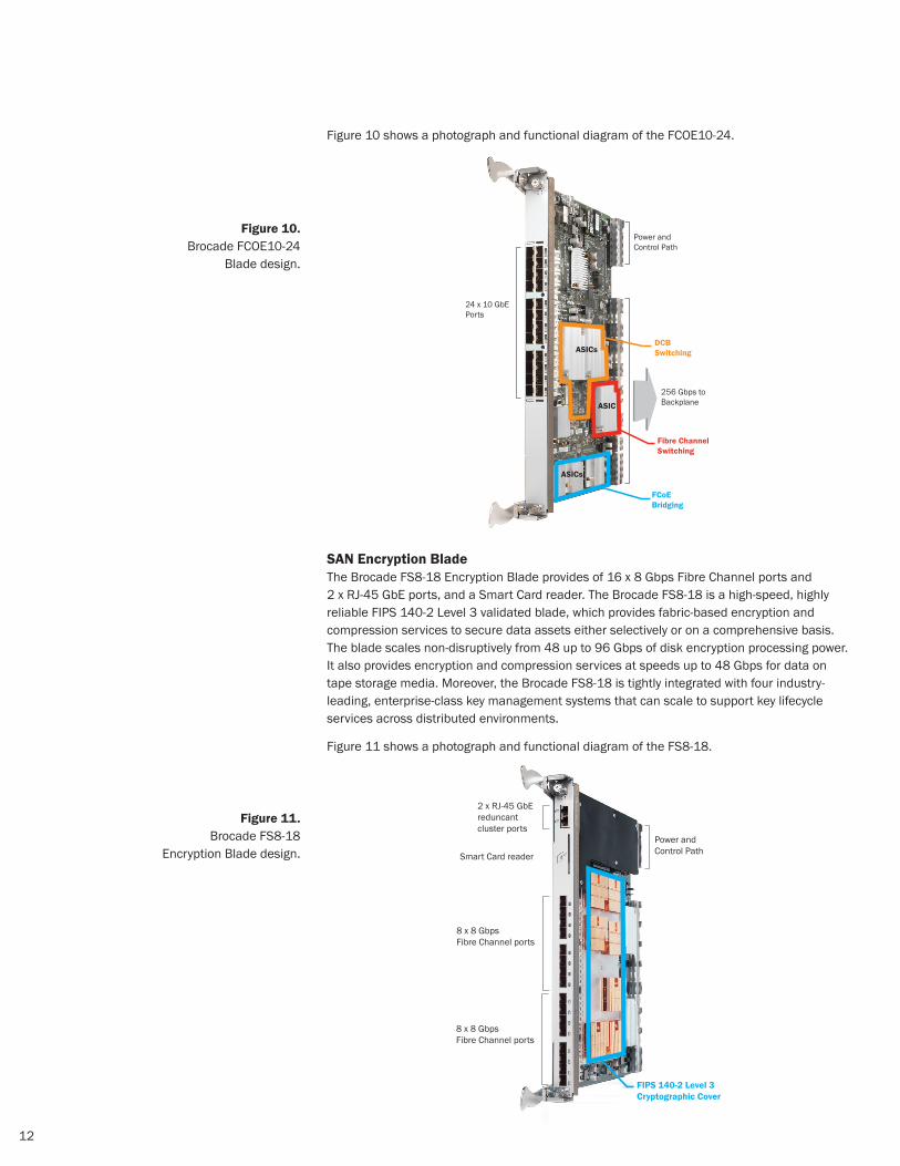
Figure 10 shows a photograph and functional diagram of the FCOE10-24.
SaN encryption BladeThe Brocade FS8-18 Encryption Blade provides of 16 x 8 Gbps Fibre Channel ports and 2 x RJ-45 GbE ports, and a Smart Card reader. The Brocade FS8-18 is a high-speed, highly reliable FIPS 140-2 Level 3 validated blade, which provides fabric-based encryption and compression services to secure data assets either selectively or on a comprehensive basis. The blade scales non-disruptively from 48 up to 96 Gbps of disk encryption processing power. It also provides encryption and compression services at speeds up to 48 Gbps for data on tape storage media. Moreover, the Brocade FS8-18 is tightly integrated with four industry-leading, enterprise-class key management systems that can scale to support key lifecycle services across distributed environments.
Figure 11 shows a photograph and functional diagram of the FS8-18.
Figure 10. Brocade FCOE10-24
Blade design.
ASIC
ASICs
Power and Control Path
256 Gbps toBackplane
24 x 10 GbEPorts
Fibre ChannelSwitching
ASICs
FCoEBridging
DCBSwitching
8 x 8 Gbps Fibre Channel ports
8 x 8 GbpsFibre Channel ports
Power and Control PathSmart Card reader
2 x RJ-45 GbEreduncantcluster ports
FIPS 140-2 Level 3Cryptographic Cover
Figure 11. Brocade FS8-18
Encryption Blade design.
13
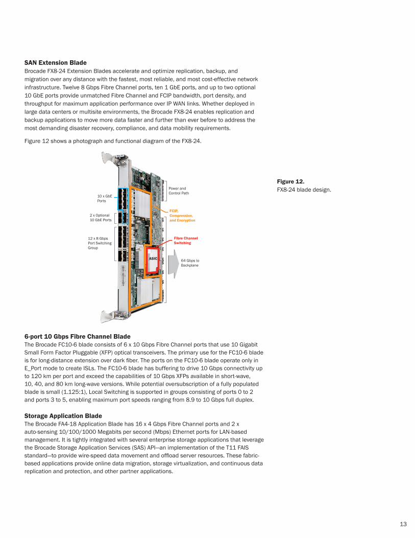
SaN extension BladeBrocade FX8-24 Extension Blades accelerate and optimize replication, backup, and migration over any distance with the fastest, most reliable, and most cost-effective network infrastructure. Twelve 8 Gbps Fibre Channel ports, ten 1 GbE ports, and up to two optional 10 GbE ports provide unmatched Fibre Channel and FCIP bandwidth, port density, and throughput for maximum application performance over IP WAN links. Whether deployed in large data centers or multisite environments, the Brocade FX8-24 enables replication and backup applications to move more data faster and further than ever before to address the most demanding disaster recovery, compliance, and data mobility requirements.
Figure 12 shows a photograph and functional diagram of the FX8-24.
6-port 10 Gbps Fibre Channel Blade The Brocade FC10-6 blade consists of 6 x 10 Gbps Fibre Channel ports that use 10 Gigabit Small Form Factor Pluggable (XFP) optical transceivers. The primary use for the FC10-6 blade is for long-distance extension over dark fiber. The ports on the FC10-6 blade operate only in E_Port mode to create ISLs. The FC10-6 blade has buffering to drive 10 Gbps connectivity up to 120 km per port and exceed the capabilities of 10 Gbps XFPs available in short-wave, 10, 40, and 80 km long-wave versions. While potential oversubscription of a fully populated blade is small (1.125:1), Local Switching is supported in groups consisting of ports 0 to 2 and ports 3 to 5, enabling maximum port speeds ranging from 8.9 to 10 Gbps full duplex.
Storage application Blade The Brocade FA4-18 Application Blade has 16 x 4 Gbps Fibre Channel ports and 2 x auto-sensing 10/100/1000 Megabits per second (Mbps) Ethernet ports for LAN-based management. It is tightly integrated with several enterprise storage applications that leverage the Brocade Storage Application Services (SAS) API—an implementation of the T11 FAIS standard—to provide wire-speed data movement and offload server resources. These fabric-based applications provide online data migration, storage virtualization, and continuous data replication and protection, and other partner applications.
ASIC
Power and Control Path
64 Gbps toBackplane
10 x GbEPorts
Fibre ChannelSwitching
FCIP,Compression,and Encryption
12 x 8 GbpsPort Switching Group
2 x Optional10 GbE Ports
Figure 12. FX8-24 blade design.

14
tHe BeNeFitS OF COre/edGe NetwOrk deSiGNThe core/edge network topology has emerged as the design of choice for large-scale, highly available, high-performance SANs constructed with multiple switches of any size.
The Brocade DCX Backbone uses an internal architecture analogous to a core/edge “fat-tree” topology, which is widely recognized as being the highest-performance arrangement of switches. Note that the Brocade DCX Backbone is not literally a fat-tree network of discrete switches, but thinking of it in this way provides a useful visualization.
While IT organizations could build a network of 40-port switches with similar performance characteristics to the Brocade DCX Backbone, it would require more than a dozen 40-port switches connected in a “fat-tree” fashion. This network would require complex cabling, management of 12+ discrete switching elements, support for higher power and cooling,
and more SFPs to support ISLs. In contrast, the Brocade DCX delivers the same high level of performance without the associated disadvantages of a large multi-switch network, bringing fat-tree performance to IT organizations that could previously not justify the investment or overhead costs.
It is important to understand, however, that the internal ASIC connections in a Brocade DCX Backbone are not E_Ports connecting a network of switches. They are considered C_Ports. Since they are not E_Ports, typical E_Port overhead is
not present on the C_Port. The Fabric OS and ASIC architecture enables the entire backbone to be a single domain and a single hop in a Fibre Channel network. Unlike a situation in which a switch is removed from a fabric, a fabric reconfiguration is not sent across the network when a port blade is removed, further simplifying operations.
In comparison to a multi-switch, fat-tree network, the Brocade DCX Backbone:
Is easier to deploy and manage•
Simplifies the cable plant by eliminating ISLs and additional SFP media•
Is far more scalable than a large network of independent domains•
Is lower in both initial CapEx and ongoing OpEx•
Has fewer active components and more component redundancy for higher reliability•
Provides multiprotocol support and routing within a single chassis •
The Brocade DCX Backbone architecture enables the entire backbone to be a single domain and a single hop in a Fibre Channel network.
15
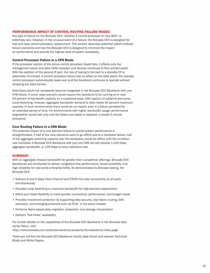
PerFOrMaNCe iMPaCt OF CONtrOL rOutiNG FaiLure MOdeSAny type of failure on the Brocade DCX—whether a control processor or core ASIC—is extremely rare. However, in the unusual event of a failure, the Brocade DCX is designed for fast and easy control processor replacement. This section describes potential (albeit unlikely) failure scenarios and how the Brocade DCX is designed to minimize the impact on performance and provide the highest level of system availability.
Control Processor Failure in a CP8 BladeIf the processor section of the active control processor blade fails, it affects only the management plane and data traffic between end devices continues to flow uninterrupted. With the addition of the second IP port, the risk of having to fail over to a standby CP is potentially minimized. A control processor failure has no effect on the data plane: the standby control processor automatically takes over and the backbone continues to operate without dropping any data frames.
Data flows would not necessarily become congested in the Brocade DCX Backbone with one CP8 failure. A worst- case scenario would require the backbone to be running at or near 50 percent of bandwidth capacity on a sustained basis. With typical I/O patterns and some Local Switching, however, aggregate bandwidth demand is often below 50 percent maximum capacity. In such environments there would be no impact, even if a failure persisted for an extended period of time. For environments with higher bandwidth usage, performance degradation would last only until the failed core blade is replaced, a simple 5-minute procedure.
Core routing Failure in a Cr8 Blade The potential impact of a core element failure to overall system performance is straightforward. If half of the core elements were to go offline due to a hardware failure, half of the aggregate switching capacity over the backplane would be offline until the condition was corrected. A Brocade DCX Backbone with just one CR8 can still provide 1,024 Gbps aggregate bandwidth, or 128 Gbps to every backbone slot.
SuMMaryWith an aggregate chassis bandwidth far greater than competitive offerings, Brocade DCX Backbones are architected to deliver congestion-free performance, broad scalability, and high reliability for real-world enterprise SANs. As demonstrated by Brocade testing, the Brocade DCX:
Delivers 8 and 4 Gbps Fibre Channel and FICON line-rate connectivity on all ports • simultaneously
Provides Local Switching to maximize bandwidth for high-demand applications•
Offers port blade flexibility to meet specific connectivity, performance, and budget needs•
Provides investment protection by supporting data security, inter-fabric routing, SAN • extension, and emerging protocols such as FCoE in the same chassis
Performs fabric-based data migration, protection, and storage virtualization•
Delivers “five-nines” availability•
For further details on the capabilities of the Brocade DCX Backbone in the Brocade data center fabric, visit: http://www.brocade.com/products-solutions/products/dcx-backbone/index.page
There you will find the Brocade DCX Backbone Family Data Sheet and relevant Technical Briefs and White Papers.
www.brocade.com
© 2010 Brocade Communications Systems, Inc. All Rights Reserved. 06/10 GA-WP-1224-01
Brocade, the B-wing symbol, BigIron, DCX, Fabric OS, FastIron, IronView, NetIron, SAN Health, ServerIron, and TurboIron are registered trademarks, and Brocade Assurance, DCFM, Extraordinary Networks, and Brocade NET Health are trademarks of Brocade Communications Systems, Inc., in the United States and/or in other countries. Other brands, products, or service names mentioned are or may be trademarks or service marks of their respective owners.
Notice: This document is for informational purposes only and does not set forth any warranty, expressed or implied, concerning any equipment, equipment feature, or service offered or to be offered by Brocade. Brocade reserves the right to make changes to this document at any time, without notice, and assumes no responsibility for its use. This informational document describes features that may not be currently available. Contact a Brocade sales office for information on feature and product availability. Export of technical data contained in this document may require an export license from the United States government.
Corporate Headquarters San Jose, CA USAT: [email protected]
european Headquarters Geneva, SwitzerlandT: +41-22-799-56-40 [email protected]
Asia Pacific Headquarters SingaporeT: +65-6538-4700 [email protected]
WHITE PAPER