d i v i s i o n 03: c o n c r e t e -...
TRANSCRIPT

Table of Contents - 1 - 03 0000
D I V I S I O N 03: C O N C R E T E
03 1000 C O N C R E T E F O R M I N G A N D A C C E S S O R I E S
03 1113 STRUCTURAL CAST-IN-PLACE CONCRETE FORMING
03 1511 CONCRETE ANCHORS AND INSERTS
03 2000 C O N C R E T E R E I N F O R C I N G
03 2100 REINFORCEMENT BARS
03 3000 C A S T - I N - P L A C E C O N C R E T E
03 3053 MISCELLANEOUS CAST-IN-PLACE CONCRETE
03 3111 NORMAL WEIGHT STRUCTURAL CONCRETE
03 3923 MEMBRANE CONCRETE CURING
03 6000 G R O U T I N G
03 6213 NON-METALLIC NON-SHRINK GROUT
03 6300 EPOXY GROUTING
END OF TABLE OF CONTENTS

Table of Contents - 2 - 03 0000
B L A N K P A G E
Project Number: 5076927-17020101 24 May 2017 Valley Park 3,4,5 &
Structural Cast-In-Place Concrete Forming - 1 - 03 1113
SECTION 03 1113
STRUCTURAL CAST-IN-PLACE CONCRETE FORMING
PART 1 - GENERAL
1.1 SUMMARY
A. Includes But Not Limited To: 1. Design, construction, and safety of formwork. 2. Furnish and install required formwork ready for placing of concrete. 3. Strip and dispose of formwork.
B. Related Requirements: 1. Section 01 0000: ‘General Requirements’:
a. Section 01 4000: ‘Quality Requirements’ for administrative and procedural requirements for quality assurance and quality control.
b. Section 01 4301: ‘Quality Assurance – Qualifications’ establishes minimum qualification levels required.
2. Section 03 3111: ‘Normal Weight Structural Concrete’. a. Tolerances for placing normal weight structural concrete. b. Pre-installation conference held jointly with other concrete related sections.
1.2 REFERENCES
A. Reference Standards: 1. American Concrete Institute:
a. ACI 318-11, ‘Building Code Requirements for Structural Concrete and Commentary'. 2. International Code Council (IBC):
a. IBC Chapter 17, ‘Structural Tests and Special Inspections’.
1.3 ADMINISTRATIVE REQUIREMENTS
A. Pre-Installation Conference: 1. Participate in pre-installation conference as specified in Section 03 3111. 2. In addition to agenda items specified in Section 01 3100 and 31 3111, review following:
a. Review Section 01 4523 for Testing and Inspection administrative requirements and responsibilities and Field Quality Control tests and inspections required of this section. 1) Review frequency of testing and inspections.
B. Scheduling: 1. Notify Testing Agency and Architect as directed in Section 03 3053 and Section 03 3111.
1.4 SUBMITTALS
A. Informational Submittals: 1. Manufacturer Instructions:
a. Printed application instructions for form release agents.
Project Number: 5076927-17020101 24 May 2017 Valley Park 3,4,5 &
Structural Cast-In-Place Concrete Forming - 2 - 03 1113
PART 2 - PRODUCTS
2.1 COMPONENTS
A. Forms: Wood, metal, or plastic as arranged by Contractor. 1. Forming material shall be compatible with specified form release agents and with finish
requirements for concrete to be left exposed or to receive a smooth rubbed finish.
2.2 ACCESSORIES
A. Form Release Agents: 1. Unexposed Surfaces Only: Contractor's option.
B. Expansion / Contraction Joints: 1. 1/2 inch (13 mm) thick. 2. Manufactured commercial fiber type:
a. Meet requirements of ASTM D1751. b. Type Two Acceptable Products:
1) Conflex by Knight-Celotex, Northfield, IL www.aknightcompany.com.2) Sealtight by W R Meadows Inc, Hampshire, IL www.wrmeadows.com. 3) Equal as approved by Architect before installation. See Section 01 6200.
3. Recycled Vinyl: a. Light gray color. b. Type Two Acceptable Products:
1) Proflex by Oscoda Plastics Inc, Oscoda, MI www.oscodaplastics.com. 2) Equal as approved by Architect before Installation. See Section 01 6200.
PART 3 - EXECUTION
3.1 INSTALLATION
A. Forms: 1. Assemble forms so forms are sufficiently tight to prevent leakage. 2. Properly brace and tie forms. 3. Provide temporary cleanouts at base of tall forms to facilitate cleaning and inspection. 4. Make proper form adjustments before, during, and after concreting. 5. Use new forms, or used forms that have been cleaned of loose concrete and other debris from
previous concreting and repaired to proper condition. Use APA Plyform B-B Class I, or APA HDO Plyform B-B Class I, on exposed to view concrete that do not receive a smooth rubbed finish.
6. Use metal cold joint forms when unable to place concrete for footings, foundations, and slabs in continuous pours.
B. Accessories: 1. General:
a. Provide for installation of inserts, templates, fastening devices, sleeves, and other accessories to be set in concrete before placing.
b. Position anchor bolts for hold-down anchors and columns and securely tie in place before placing concrete.
2. Expansion Joints: a. Install at joints between floor slab and foundation wall where shown on Drawings.
C. Form Removal: 1. Removal of forms can usually be accomplished in twelve (12) to twenty four (24) hours.
Project Number: 5076927-17020101 24 May 2017 Valley Park 3,4,5 &
Structural Cast-In-Place Concrete Forming - 3 - 03 1113
2. If temperature is below 50 deg F (10 deg C) or if concrete (stairs, beams, etc) depends on forms for structural support, leave forms intact for sufficient period for concrete to reach adequate strength.
3. For exposed to view surfaces that receive a smooth rubbed finish, remove forms while concrete is still “green”.
4. Metal bars or prys should not be used. Use wood wedges, tapping gradually when necessary.
END OF SECTION

Project Number: 5076927-17020101 24 May 2017 Valley Park 3,4,5 &
Structural Cast-In-Place Concrete Forming - 4 - 03 1113
B L A N K P A G E
Project Number: 5076927-17020101 24 May 2017 Valley Park 3,4,5 &
Concrete Anchors And Inserts - 1 - 03 1511
SECTION 03 1511
CONCRETE ANCHORS AND INSERTS
PART 1 - GENERAL
1.1 SUMMARY
A. Products Furnished But Not Installed Under This Section: 1. Cast-in anchors for concrete. 2. Headed concrete anchor studs for concrete. 3. Deformed bar anchors for concrete. 4. Adhesive anchors and inserts for concrete. 5. Drilled-in mechanical anchors for concrete. 6. Screw anchors for concrete. 7. Concrete anchors and inserts not specified elsewhere.
B. Related Requirements: 1. Section 01 0000: ‘General Requirements’:
a. Section 01 1200: 'Multiple Contract Summary' for Owner Furnished Testing and Inspecting Services.
a. Section 01 3100: ‘Project Management and Coordination’ for pre-installation conference. b. Section 01 4000: ‘Quality Requirements’ for administrative and procedural requirements for
quality assurance and quality control. c. Section 01 4301: ‘Quality Assurance – Qualifications’ establishes minimum qualification
levels required. d. Section 01 4523: ‘Testing and Inspecting Services’ for testing and inspection, and testing
laboratory services for materials, products, and construction methods. e. Section 01 7800: ‘Closeout Submittals’.
2. Section 03 3111: 'Normal-Weight Structural Concrete' for installation of cast-in-place anchors and inserts.
1.2 REFERENCES
A. Association Publications: 1. Council of American Structural Engineers. CASE Form 101: Statement of Special Inspections.
Washington, DC: CASE, 2001. (c/o American Council of Engineering Companies, 1015 15th St.,
NW, Washington, DC 20005; 202-347-7474; www.acec.org).
B. Definitions (Following are specifically referenced for testing): 1. Accreditation: Process in which certification of competency, authority, or credibility is presented.
Verify that laboratories have an appropriate quality management system and can properly perform certain test methods (e.g., ANSI, ASTM, and ISO test methods) and calibration parameters according to their scopes of accreditation.
2. Approved: To authorize, endorse, validate, confirm, or agree to. 3. Field Quality Control: Testing, Inspections, Special Testing and Special Inspections to assure
compliance to Contract Documents. 4. Inspection/Special Inspection: Inspection of materials, installation, fabrication, erection or
placement of components and connections requiring special expertise to ensure compliance with approved construction documents and referenced standards: a. Inspection: Not required by code provisions but may be required by Contract Documents. b. Special Inspection: Required by code provisions and by Contract Documents. c. Inspection-Continuous: Full-time observation of the Work requiring inspection by approved
inspector who is present in area where the Work is being performed.

Project Number: 5076927-17020101 24 May 2017 Valley Park 3,4,5 &
Concrete Anchors And Inserts - 2 - 03 1511
d. Inspection-Periodic: Part-time or intermittent observation of the Work requiring inspection by approved inspector who is present in area where the Work has been or is being performed and at completion of the Work.
5. Installer/Applicator/Erector: Contractor or another entity engaged by Contractor as an employee, Subcontractor, or Sub-subcontractor, to perform particular construction operation, including installation, erection, application, and similar operations.
6. Observation: Visual observation of building / site elements or structural system by registered design professional for general conformance to approved construction documents at significant construction stages and at completion. Observation does not include or waive responsibility for performing inspections or special inspections.
7. Owner’s Representative: Owner’s Designated Representative (Project Manager or Facilities Manager) who will have express authority to bind Owner with respect to all matters requiring Owner’s approval or authorization.
8. Preconstruction Testing: Tests and inspections that are performed specifically for Project before products and materials are incorporated into the Work to verify performance or compliance with specified criteria.
9. Product Testing: Tests and inspections that are performed by testing agency qualified to conduct product testing and acceptable to authorities having jurisdiction, to establish product performance and compliance with industry standards.
10. Quality Assurance: Testing, Inspections, Special Testing and Special Inspections provided for by Owner.
11. Quality Control: Testing, Inspections, Special Testing and Special Inspections provided for by Contractor.
12. Service Provider: Agency or firm qualified to perform required tests and inspections. 13. Source Quality Control Testing: Tests and inspections that are performed at source, i.e., plant,
mill, factory, or shop. 14. Special Inspection: See Inspection. 15. Special Inspector: Certified individual or firm that implements special inspection program for
project. 16. Special Test: See Test. 17. Test/Special Test: Field or laboratory tests to determine characteristics and quality of building
materials and workmanship. a. Test: Not required by code provisions but may be required by Contract Documents. b. Special Test: Required by code provisions and by Contract Documents.
18. Testing Agency: Entity engaged to perform specific tests, inspections, or both. 19. Testing Agency Laboratory: Agency or firm qualified to perform field and laboratory tests to
determine characteristics and quality of materials and workmanship. 20. Verification: Act of reviewing, inspecting, testing, etc. to establish and document that product,
service, or system meets regulatory, standard, or specification requirements.
C. Reference Standards: 1. ASTM International:
a. ASTM A108-07, ‘Standard Specification for Steel Bar, Carbon and Alloy, Cold Finished’. b. ASTM A307-10, 'Standard Specification for Carbon Steel Bolts and Studs, 60 000 psi
Tensile Strength’. c. ASTM A325-10, ‘Standard Specification for Structural Bolts, Steel, Heat Treated, 120/105 ksi
Minimum Tensile Strength’. d. ASTM A490-12, ‘Standard Specification for Structural Bolts, Alloy Steel, Heat Treated, 150
ksi Minimum Tensile Strength’. e. ASTM A490M-12, ‘Standard Specification for High-Strength Steel Bolts, Classes 10.9 and
10.9.3, for Structural Steel Joints [Metric]’. f. ASTM A496/A496M-07, ‘Standard Specification for Steel Wire, Deformed, for Concrete
Reinforcement’. g. ASTM A563-07a, 'Standard Specification for Carbon and Alloy Steel Nuts’. h. ASTM A615/A615M-12, ‘Standard Specification for Deformed and Plain Carbon-Steel Bars
for Concrete Reinforcement’. i. ASTM A706/A706M-09b, ‘Standard Specification for Low-Alloy Steel Deformed and Plain
Bars for Concrete Reinforcement’.

Project Number: 5076927-17020101 24 May 2017 Valley Park 3,4,5 &
Concrete Anchors And Inserts - 3 - 03 1511
j. ASTM C1077-11c, ‘Standard Practice for Laboratories Testing Concrete and Concrete Aggregates for Use in Construction and Criteria for Laboratory Evaluation’.
k. ASTM D3666-11, ‘Standard Specification for Minimum Requirements for Agencies Testing and Inspecting Road and Paving Materials’.
l. ASTM D3740-12a, ‘Standard Practice for Minimum Requirements for Agencies Engaged in Testing and/or Inspection of Soil and Rock as Used in Engineering Design and Construction’.
m. ASTM E329-11a: ‘Standard Specification for Agencies Engaged in Construction Inspection and/or Testing’.
n. ASTM E543-09, ‘Standard Specification for Agencies Performing Nondestructive Testing’. o. ASTM E1212-09, ‘Standard Practice for Quality Management Systems for Nondestructive
Testing Agencies’. p. ASTM F1554-07ae1, ‘Standard Specification for Anchor Bolts, Steel, 36, 55, and 105-ksi
Yield Strength’. 2. International Code Council (IBC):
a. IBC Chapter 17, ‘Structural Tests and Special Inspections’. b. ICC/ES AC193, ‘Acceptance Criteria For Mechanical Anchors in Concrete Elements’
(approved June 2012). c. ICC/ES AC308 ‘Acceptance Criteria For Post-Installed Adhesive Anchors In Concrete
Elements’ (approved Feburary 2012, compliance date July 2013). d. ICC / ESR-1056, ‘Titen HD Screw Anchors’ (March 1, 2012). e. ICC / ESR-3187, ‘Hilti HIT HY 200 Max Adhesive Anchoring Systems’ (January 1, 2012).
1.3 ADMINISTRATIVE REQUIREMENTS
A. Scheduling: 1. Inspection shall be performed according to Manufacturer’s submitted ICC ES Evaluation Report. 2. Notify Testing Agency and Architect one week before installing anchors so testing may be
scheduled.
1.4 SUBMITTALS
A. Action Submittals: 1. Product Data:
a. Manufacturer's product literature for each item.
B. Informational Submittals: 1. Test And Evaluation Reports:
a. ICC ES Evaluation Report indicating conformance with current applicable ICC ES Acceptance Criteria.
2. Manufacturer’s Instructions: a. Manufacturer's published installation recommendations for each item.
1.5 SUBMITTALS
A. Closeout Submittals: 1. Include following in Operations And Maintenance Manual specified in Section 01 7800:
a. Record Documentation: 1) Testing and Inspection Reports:
a) Testing Agency testing and inspecting reports of Drilled-In Mechanical Anchors / Adhesive Anchors / Screw Anchors and / or Headed Concrete Anchor Studs / Deformed Bar Anchors.
Project Number: 5076927-17020101 24 May 2017 Valley Park 3,4,5 &
Concrete Anchors And Inserts - 4 - 03 1511
1.6 QUALITY ASSURANCE
A. Qualifications: 1. Manufacturer:
a. Having sufficient capacity to produce and deliver required materials without causing delay in work.
2. Installer: a. Acceptable to Manufacturer, experienced in performing work of this section and has
specialized in installation of work similar to that required for this project.
B. Testing and Inspection. 1. Owner will provide Testing and Inspection for Drilled-In Mechanical Anchors / Adhesive Anchors /
Screw Anchors and / or Headed Concrete Anchor Studs / Deformed Bar Anchors. a. See Section 01 1200: ‘Multiple Contract Summary’.
1.7 DELIVERY, STORAGE, AND HANDLING
A. Delivery And Acceptance Requirements: 1. Materials shall be delivered in original, unopened packages with labels intact.
B. Storage And Handling Requirements: 1. Store materials protected from exposure to harmful weather conditions and as directed by
Manufacturer.
PART 2 - PRODUCTS
2.1 MATERIALS
A. Manufactured Units: 1. General:
a. Use hot-dipped galvanized or stainless steel with matching nuts and washers in exterior and moist interior applications unless indicated otherwise on Drawings.
b. Nut: Conform to requirements of ASTM A563, Grade A, Hex. 2. Threaded rod for adhesive anchors and cast-in anchors:
a. Conform to requirements of ASTM A307, Grade A or ASTM F1554. 3. Anchor Bolts:
a. J-Bolts: 1) Non-headed type threaded 2 inches (50 mm) minimum conforming to requirements of
ASTM F1554, Grade A. 2) Anchor hook to project 2 inches (50 mm) minimum including bolt diameter.
b. Headed Bolts: 1) Headed type threaded 2 inches (50 mm) minimum conforming to requirements of ASTM
F1554, Grade A. 4. Rebar:
a. Composed of deformed carbon steel meeting requirements of ASTM A706/A706M, Grade 60.
5. Adhesive Anchors: a. Cartridge Injection Adhesive Anchors. b. Products shall have current ICC ES Evaluation report conforming to current ICC ES
Acceptance Criteria AC308 for concrete. c. Rod diameter and embedment length as indicated on Drawings. d. Type Two Acceptable Products:
1) HIT-HY200 Epoxy Adhesive by Hilti Fastening Systems, Tulsa, OK www.us.hilti.com. 2) PE1000+ by Powers Fasteners Inc., Brewster NY www.powers.com.
Project Number: 5076927-17020101 24 May 2017 Valley Park 3,4,5 &
Concrete Anchors And Inserts - 5 - 03 1511
3) SET-XP Epoxy by Simpson Strong-Tie Co., Pleasanton, CA www.simpsonanchors.com.
4) Equal as approved by Architect before installation. See Section 01 6200. 6. Drilled-In Mechanical Anchors (Expansion Bolts):
a. Products shall have current ICC ES Evaluation report conforming to current ICC ES Acceptance Criteria AC193 for concrete.
b. Type Two Acceptable Products: 1) KWIK Bolt TZ Expansion Anchor by Hilti Fastening Systems, Tulsa, OK
www.us.hilti.com. 2) KWIK-HUS EZ-I Internally Threaded Screw Anchor by Hilti Fastening Systems, Tulsa,
OK www.us.hilti.com. 3) HSL-3 Heavy Duty Expansion Anchor by Hilti Fastening Systems, Tulsa, OK
www.us.hilti.com. 4) HDA Undercut Anchor by Hilti Fastening Systems, Tulsa, OK www.us.hilti.com. 5) Power-Stud +SD1 by Powers Fasteners Inc., Brewster NY www.powers.com. 6) Strong-Bolt by Simpson Strong-Tie Co., Pleasanton, CA www.simpsonanchors.com. 7) Equal as approved by Architect before installation. See Section 01 6200.
7. Screw Anchors: a. Provide anchors with length identification markings conforming to ICC ES AC 193 for
concrete. b. Type Two Acceptable Products:
1) Wedge-Bolt+ by Powers Fasteners Inc., Brewster NY www.powers.com. 2) Titen HD Screws by Simpson Strong Tie Co, Dublin, CA www.strongtie.com. 3) Equals as approved by Architect through shop drawing submittal before installation.
See Section 01 6200.
PART 3 - EXECUTION
3.1 EXAMINATION
A. Verification Of Conditions: 1. Embedded Items:
a. Identify position of reinforcing steel and other embedded items before drilling holes for anchors: 1) Exercise care in coring or drilling to avoid damaging existing reinforcing or embedded
items. 2) Take precautions as necessary to avoid damaging pre-stressing tendons, electrical and
telecommunications conduit, and gas lines. b. Notify Engineer if reinforcing steel or other embedded items are encountered during drilling.
2. Base Material Strength: a. Unless otherwise specified, do not drill holes in concrete until concrete has achieved full
design strength.
3.2 PREPARATION
A. Surface Preparation: 1. Clean surfaces prior to installation. 2. Prepare surface in accordance with Manufacturer’s written recommendations.
3.3 INSTALLATION
A. Drilled-In Anchors: 1. General:
Project Number: 5076927-17020101 24 May 2017 Valley Park 3,4,5 &
Concrete Anchors And Inserts - 6 - 03 1511
a. Drill holes with rotary impact hammer drills using carbide-tipped bits or core drills using diamond core bits.
b. Unless otherwise shown on Drawings, drill holes perpendicular to concrete surface. c. Where anchors are to be installed in cored holes, use core bits with matched tolerances
specified by Manufacturer. Cores holes may only be used if acceptable to Manufacturer. d. Perform anchor installation in accordance with Manufacturer’s published instructions.
2. Adhesive Anchors: a. Clean holes in accordance with Manufacturer’s published instructions before installation of
adhesive: 1) Follow Manufacturer’s recommendations to ensure proper mixing of adhesive
components. b. Adhesive:
1) Inject adhesive into holes proceeding from bottom of hole and progressing toward surface so as to avoid introduction of air pockets into adhesive.
2) Inject sufficient adhesive into hole to ensure that annular gap is filled to surface. 3) Remove excess adhesive from surface.
c. Shim anchors with suitable device to center anchor in hole. Do not disturb or load anchors before Manufacturer’s specified cure time has elapsed.
d. Temperature: 1) Observe Manufacturer’s recommendations with respect to installation temperatures for
adhesive anchors. 2) Base material temperatures must be maintained above minimum temperatures allowed
by Manufacturer for full required epoxy cure time. 3. Drilled-in Mechanical Anchors (Expansion Bolts):
a. Protect threads from damage during anchor installation. b. Set anchors to Manufacturer’s recommended torque, using a torque wrench. Following
attainment of 10 percent of specified torque, 100 percent of specified torque shall be reached within 7 or fewer complete turns of nut. If specified torque is not achieved within required number of turns, remove and replace anchor, unless otherwise directed by Architect.
4. Screw Anchors: a. Protect threads from damage during anchor installation. b. Set anchors to Manufacturer’s recommended torque, using a torque wrench.
3.4 FIELD QUALITY CONTROL
A. Field Tests and Inspections: 1. Drill-In Mechanical Anchors / Adhesive Anchors / Screw Anchors:
a. Certified Inspector from Testing Agency shall verify procedures used for installation of all concrete anchors and monitor their installation for compliance with Manufacturer’s requirements.
b. Inspections: 1) Inspections shall include required verification and inspection of anchors as referenced
in IBC Table 1704.4 and in accordance with ACI 318 and applicable ASTM material standards. Periodic and continuous inspections include: a) Inspection of bolts to be installed in concrete prior to and during placement of
concrete (continuous). b) Inspection of anchors installed in hardened concrete (periodic).
c. Testing: 1) Ten percent (10%) of each type and size of drilled-in anchor shall be proof loaded by
Testing Agency’s testing laboratory or as directed by Architect. Adhesive anchors will not be torque tested unless otherwise directed by Architect. If more than 10 percent of tested anchors fail to achieve specified torque or proof load within limits defined on Drawings, all anchors of same diameter and type as failed anchors shall be tested at Contractors expense, unless otherwise instructed by Architect. a) Torque will be applied with calibrated torque wrench.
Project Number: 5076927-17020101 24 May 2017 Valley Park 3,4,5 &
Concrete Anchors And Inserts - 7 - 03 1511
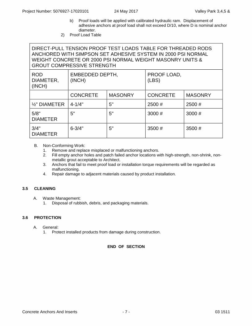
b) Proof loads will be applied with calibrated hydraulic ram. Displacement of adhesive anchors at proof load shall not exceed D/10, where D is nominal anchor diameter.
2) Proof Load Table
B. Non-Conforming Work: 1. Remove and replace misplaced or malfunctioning anchors. 2. Fill empty anchor holes and patch failed anchor locations with high-strength, non-shrink, non-
metallic grout acceptable to Architect. 3. Anchors that fail to meet proof load or installation torque requirements will be regarded as
malfunctioning. 4. Repair damage to adjacent materials caused by product installation.
3.5 CLEANING
A. Waste Management: 1. Disposal of rubbish, debris, and packaging materials.
3.6 PROTECTION
A. General: 1. Protect installed products from damage during construction.
END OF SECTION
DIRECT-PULL TENSION PROOF TEST LOADS TABLE FOR THREADED RODS ANCHORED WITH SIMPSON SET ADHESIVE SYSTEM IN 2000 PSI NORMAL WEIGHT CONCRETE OR 2000 PSI NORMAL WEIGHT MASONRY UNITS & GROUT COMPRESSIVE STRENGTH
ROD DIAMETER, (INCH)
EMBEDDED DEPTH, (INCH)
PROOF LOAD, (LBS)
CONCRETE MASONRY CONCRETE MASONRY
½" DIAMETER 4-1/4" 5" 2500 # 2500 #
5/8" DIAMETER
5" 5" 3000 # 3000 #
3/4" DIAMETER
6-3/4" 5" 3500 # 3500 #
Project Number: 5076927-17020101 24 May 2017 Valley Park 3,4,5 &
Concrete Anchors And Inserts - 8 - 03 1511
B L A N K P A G E
Project Number: 5076927-17020101 24 May 2017 Valley Park 3,4,5 &
Reinforcement Bars - 1 - 03 2100
SECTION 03 2100
REINFORCEMENT BARS
PART 1 - GENERAL
1.1 SUMMARY
A. Includes But Not Limited To: 1. Furnish and install concrete reinforcement bars as described in Contract Documents.
B. Related Requirements: 1. Section 01 0000: ‘General Requirements’:
a. Section 01 1200: 'Multiple Contract Summary' for Owner Furnished Testing and Inspecting Services.
b. Section 01 3100: ‘Project Management and Coordination’ for pre-installation conference. c. Section 01 4000: ‘Quality Requirements’ for administrative and procedural requirements for
quality assurance and quality control. d. Section 01 4301: ‘Quality Assurance – Qualifications’ establishes minimum qualification
levels required. e. Section 01 4523: ‘Testing and Inspecting Services’ for testing and inspection, and testing
laboratory services for materials, products, and construction methods. f. Section 01 7800: ‘Closeout Submittals’.
2. Section 03 1113: Structural Cast-In-Place Concrete Forming'. 3. Section 03 3111: ‘Normal Weight Structural Concrete’.
a. Reinforcement installed in concrete. b. Pre-installation conference held jointly with other concrete related sections.
1.2 REFERENCES
A. Association Publications: 1. Council of American Structural Engineers. CASE Form 101: Statement of Special Inspections.
Washington, DC: CASE, 2001. (c/o American Council of Engineering Companies, 1015 15th St.,
NW, Washington, DC 20005; 202-347-7474; www.acec.org).
B. Definitions (Following are specifically referenced for testing): 1. Accreditation: Process in which certification of competency, authority, or credibility is presented.
Verify that laboratories have an appropriate quality management system and can properly perform certain test methods (e.g., ANSI, ASTM, and ISO test methods) and calibration parameters according to their scopes of accreditation.
2. Field Quality Control: Testing, Inspections, Special Testing and Special Inspections to assure compliance to Contract Documents.
3. Inspection/Special Inspection: Inspection of materials, installation, fabrication, erection or placement of components and connections requiring special expertise to ensure compliance with approved construction documents and referenced standards: a. Inspection: Not required by code provisions but may be required by Contract Documents. b. Special Inspection: Required by code provisions and by Contract Documents. c. Inspection-Continuous: Full-time observation of the Work requiring inspection by approved
inspector who is present in area where the Work is being performed. d. Inspection-Periodic: Part-time or intermittent observation of the Work requiring inspection by
approved inspector who is present in area where the Work has been or is being performed and at completion of the Work.
4. Observation: Visual observation of building / site elements or structural system by registered design professional for general conformance to approved construction documents at significant construction stages and at completion. Observation does not include or waive responsibility for performing inspections or special inspections.
Project Number: 5076927-17020101 24 May 2017 Valley Park 3,4,5 &
Reinforcement Bars - 2 - 03 2100
5. Preconstruction Testing: Tests and inspections that are performed specifically for Project before products and materials are incorporated into the Work to verify performance or compliance with specified criteria.
6. Product Testing: Tests and inspections that are performed by testing agency qualified to conduct product testing and acceptable to authorities having jurisdiction, to establish product performance and compliance with industry standards.
7. Quality Assurance: Testing, Inspections, Special Testing and Special Inspections provided for by Owner.
8. Quality Control: Testing, Inspections, Special Testing and Special Inspections provided for by Contractor.
9. Service Provider: Agency or firm qualified to perform required tests and inspections. 10. Source Quality Control Testing: Tests and inspections that are performed at source, i.e., plant,
mill, factory, or shop. 11. Special Inspection: See Inspection. 12. Special Inspector: Certified individual or firm that implements special inspection program for
project. 13. Special Test: See Test. 14. Test/Special Test: Field or laboratory tests to determine characteristics and quality of building
materials and workmanship. a. Test: Not required by code provisions but may be required by Contract Documents. b. Special Test: Required by code provisions and by Contract Documents.
15. Testing Agency: Entity engaged to perform specific tests, inspections, or both. 16. Testing Agency Laboratory: Agency or firm qualified to perform field and laboratory tests to
determine characteristics and quality of materials and workmanship. 17. Verification: Act of reviewing, inspecting, testing, etc. to establish and document that product,
service, or system meets regulatory, standard, or specification requirements.
C. Reference Standards: 1. American Concrete Institute:
a. ACI 117-10: ‘Specifications for Tolerances for Concrete Construction and Materials and Commentary’.
b. ACI 117M-10: ‘Specifications for Tolerances for Concrete Construction and Materials and Commentary (Metric)’.
c. ACI 318-11, ‘Building Code Requirements for Structural Concrete and Commentary'. 2. ASTM International (Following are specifically referenced for reinforcement bars testing):
a. ASTM A615/A615M-12, ‘Standard Specification for Deformed and Plain Carbon-Steel Bars for Concrete Reinforcement'.
3. ASTM International (Following are specifically referenced for Testing Agencies): a. ASTM E329-11c: ‘Standard Specification for Agencies Engaged in Construction Inspection
and/or Testing'. b. ASTM E543-09, ‘Standard Specification for Agencies Performing Nondestructive Testing'. c. ASTM E1212-09, ‘Standard Practice for Quality Management Systems for Nondestructive
Testing Agencies'.
1.3 ADMINISTRATIVE REQUIREMENTS
A. Pre-Installation Conferences: 1. Participate in pre-installation conference as specified in Section 03 3111. 2. In addition to agenda items specified in Section 01 3100, and Section 03 3111, review following:
a. Installation scheduling and reinforcing placement. b. Review Section 01 4523 for Testing and Inspection administrative requirements and
responsibilities and Field Quality Control tests and inspections required of this section. 1) Review frequency of testing and inspections.
B. Scheduling: 1. Notify Testing Agency and Architect as directed in Section 03 3053 and Section 03 3111.
Project Number: 5076927-17020101 24 May 2017 Valley Park 3,4,5 &
Reinforcement Bars - 3 - 03 2100
1.4 SUBMITTALS
A. Action Submittals: 1. Shop Drawings:
a. Reinforcing placement drawings.
B. Informational Submittals: 1. Certificates:
a. Mill certificates for mill tests for reinforcing in accordance with ASTM A615/A615M.
C. Closeout Submittals: 1. Include following in Operations And Maintenance Manual specified in Section 01 7800:
a. Record Documentation: 1) Testing and Inspection Reports:
a) Testing Agency Inspection Reports of reinforcement bars.
1.5 QUALITY ASSURANCE
A. Regulatory Agency Sustainability Approvals: 1. Comply with provisions of following codes and standards except where more stringent
requirements are shown or specified: a. ACI 318, ‘Building Code Requirements for Structural Concrete and Commentary'. b. Concrete Reinforcing Steel Institute (CRSI) 'Manual of Standard Practice'.
B. Qualifications: 1. Throughout progress of the work of this section, provide at least one (1) person who shall be
thoroughly familiar with Construction Documents and other applicable specified requirements, completely trained and experienced in necessary skills, and who shall be present at site and shall direct all work performed under this Section: a. In actual installation of the work of this Section, use adequate numbers of skilled workmen to
ensure installation in strict accordance with approved design. b. In acceptance or rejection of work performed under this Section, no allowance will be made
for lack of skill on part of workmen.
C. Testing and Inspection: 1. Owner will provide Testing and Inspection for inspection of reinforcement bars:
a. See Section 01 1200: ‘Multiple Contract Summary’.
1.6 DELIVERY, STORAGE, AND HANDLING
A. Delivery And Acceptance Requirements: 1. Deliver bars separated by size and tagged with manufacturer's heat or test identification number. 2. Reinforcement bars shall be free of heavy rust scales and flakes, or other coating at time of
delivery and placing.
B. Storage And Handling Requirements: 1. Properly protect rebar on site after delivery.
PART 2 - PRODUCTS
2.1 MATERIAL
USA PROJECTS: Include following paragraph.
Project Number: 5076927-17020101 24 May 2017 Valley Park 3,4,5 &
Reinforcement Bars - 4 - 03 2100
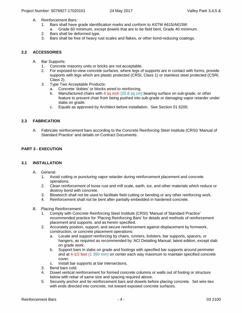
A. Reinforcement Bars: 1. Bars shall have grade identification marks and conform to ASTM A615/A615M:
a. Grade 60 minimum, except dowels that are to be field bent, Grade 40 minimum. 2. Bars shall be deformed type. 3. Bars shall be free of heavy rust scales and flakes, or other bond-reducing coatings.
2.2 ACCESSORIES
A. Bar Supports: 1. Concrete masonry units or bricks are not acceptable. 2. For exposed-to-view concrete surfaces, where legs of supports are in contact with forms, provide
supports with legs which are plastic protected (CRSI, Class 1) or stainless steel protected (CSRI, Class 2).
3. Type Two Acceptable Products: a. Concrete 'dobies' or blocks wired to reinforcing. b. Manufactured chairs with 4 sq inch (25.8 sq cm) bearing surface on sub-grade, or other
feature to prevent chair from being pushed into sub-grade or damaging vapor retarder under slabs on grade.
c. Equals as approved by Architect before installation. See Section 01 6200.
2.3 FABRICATION
A. Fabricate reinforcement bars according to the Concrete Reinforcing Steel Institute (CRSI) 'Manual of Standard Practice' and details on Contract Documents.
PART 3 - EXECUTION
3.1 INSTALLATION
A. General: 1. Avoid cutting or puncturing vapor retarder during reinforcement placement and concrete
operations. 2. Clean reinforcement of loose rust and mill scale, earth, ice, and other materials which reduce or
destroy bond with concrete. 3. Blowtorch shall not be used to facilitate field cutting or bending or any other reinforcing work. 4. Reinforcement shall not be bent after partially embedded in hardened concrete.
B. Placing Reinforcement: 1. Comply with Concrete Reinforcing Steel Institute (CRSI) 'Manual of Standard Practice'
recommended practice for 'Placing Reinforcing Bars' for details and methods of reinforcement placement and supports. and as herein specified.
2. Accurately position, support, and secure reinforcement against displacement by formwork, construction, or concrete placement operations: a. Locate and support reinforcing by chairs, runners, bolsters, bar supports, spacers, or
hangers, as required as recommended by 'ACI Detailing Manual, latest edition, except slab on grade work.
b. Support bars in slabs on grade and footings with specified bar supports around perimeter and at 4-1/2 feet (1 350 mm) on center each way maximum to maintain specified concrete cover.
c. Install bar supports at bar intersections. 3. Bend bars cold. 4. Dowel vertical reinforcement for formed concrete columns or walls out of footing or structure
below with rebar of same size and spacing required above. 5. Securely anchor and tie reinforcement bars and dowels before placing concrete. Set wire ties
with ends directed into concrete, not toward exposed concrete surfaces.
Project Number: 5076927-17020101 24 May 2017 Valley Park 3,4,5 &
Reinforcement Bars - 5 - 03 2100
C. Splices: 1. Non-Concrete Structural System:
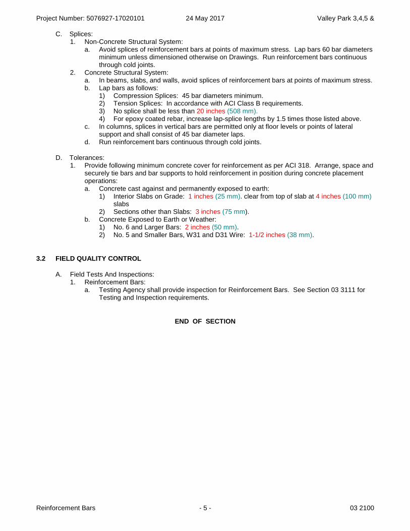
a. Avoid splices of reinforcement bars at points of maximum stress. Lap bars 60 bar diameters minimum unless dimensioned otherwise on Drawings. Run reinforcement bars continuous through cold joints.
2. Concrete Structural System: a. In beams, slabs, and walls, avoid splices of reinforcement bars at points of maximum stress. b. Lap bars as follows:
1) Compression Splices: 45 bar diameters minimum. 2) Tension Splices: In accordance with ACI Class B requirements. 3) No splice shall be less than 20 inches (508 mm).4) For epoxy coated rebar, increase lap-splice lengths by 1.5 times those listed above.
c. In columns, splices in vertical bars are permitted only at floor levels or points of lateral support and shall consist of 45 bar diameter laps.
d. Run reinforcement bars continuous through cold joints.
D. Tolerances: 1. Provide following minimum concrete cover for reinforcement as per ACI 318. Arrange, space and
securely tie bars and bar supports to hold reinforcement in position during concrete placement operations: a. Concrete cast against and permanently exposed to earth:
1) Interior Slabs on Grade: 1 inches (25 mm). clear from top of slab at 4 inches (100 mm)slabs
2) Sections other than Slabs: 3 inches (75 mm). b. Concrete Exposed to Earth or Weather:
1) No. 6 and Larger Bars: 2 inches (50 mm). 2) No. 5 and Smaller Bars, W31 and D31 Wire: 1-1/2 inches (38 mm).
3.2 FIELD QUALITY CONTROL
A. Field Tests And Inspections: 1. Reinforcement Bars:
a. Testing Agency shall provide inspection for Reinforcement Bars. See Section 03 3111 for Testing and Inspection requirements.
END OF SECTION
Project Number: 5076927-17020101 24 May 2017 Valley Park 3,4,5 &
Reinforcement Bars - 6 - 03 2100
B L A N K P A G E

Project Number: 5076927-17020101 24 May 2017 Valley Park 3,4,5 &
Miscellaneous Exterior Cast-In-Place Concrete - 1 - 03 3053
SECTION 03 3053
MISCELLANEOUS EXTERIOR CAST-IN-PLACE CONCRETE
PART 1 - GENERAL
1.1 SUMMARY
A. Includes But Not Limited To: 1. Compact aggregate base for miscellaneous cast-in-place concrete as described in Contract
Documents. 2. Furnish and install miscellaneous cast-in-place concrete and equipment pads as described in
Contract Documents. 3. Furnish and install sealants and curing compounds as described in Contract Documents.
B. Related Requirements: 1. Section 01 0000: ‘General Requirements’:
a. Section 01 1200: 'Multiple Contract Summary' for Owner Furnished Testing and Inspecting Services.
b. Section 01 3100: ‘Project Management and Coordination’ for pre-installation conference. c. Section 01 4000: ‘Quality Requirements’ for administrative and procedural requirements for
quality assurance and quality control. d. Section 01 4301: ‘Quality Assurance – Qualifications’ establishes minimum qualification
levels required. e. Section 01 4523: ‘Testing and Inspecting Services’ for testing and inspection, and testing
laboratory services for materials, products, and construction methods. f. Section 01 7800: ‘Closeout Submittals’.
2. Section 03 1113: ‘Structural Cast-In-Place Concrete Forming’. 3. Section 03 3111: ‘Normal Weight Structural Concrete’ for:
a. Concrete mix information and use admixtures. b. Field Quality Control Testing and Inspection requirements for concrete. c. Pre-installation conference held jointly with other concrete related sections.
4. Section 03 3923: 'Membrane Concrete Curing' for application. 5. Section 07 9213: 'Elastomeric Joint Sealant' for quality of sealants. 6. Section 31 0501: ‘Common Earthwork Requirements’ for:
a. General procedures and requirements for earthwork. b. Pre-installation conference held jointly with other common earthwork related sections.
7. Section 31 1123: 'Aggregate Base' for installation of aggregate base. 8. Section 31 2323: 'Fill' for compaction procedures and tolerances.
1.2 REFERENCES
A. Association Publications: 1. American Concrete Institute, Farmington Hills, MI www.concrete.org. Abstracts of ACI
Periodicals and Publications. a. ACI 224R-01, ‘Control of Cracking in Concrete Structures’ (Reapproved 2008). b. ACI 224.1R-07, ‘Causes, Evaluation, and Repair of Cracks in Concrete Structures’ (March 1,
2007). c. ACI 224.2R-92: ‘Cracking of Concrete Members in Direct Tension’ (Reapproved 2004). d. ACI 224.3R-95, ‘Joints in Concrete Construction’ (Reapproved 2008). e. ACI 302.1R-04: ‘Guide for Concrete Floor and Slab Construction' (March 23, 2004). f. ACI 305R-10, ‘Guide to Hot Weather Concreting’. g. ACI 306R-10, ‘Guide to Cold Weather Concreting’.
2. Council of American Structural Engineers. CASE Form 101: Statement of Special Inspections. Washington, DC: CASE, 2001. (c/o American Council of Engineering Companies, 1015 15
th St.,
NW, Washington, DC 20005; 202-347-7474; www.acec.org).
Project Number: 5076927-17020101 24 May 2017 Valley Park 3,4,5 &
Miscellaneous Exterior Cast-In-Place Concrete - 2 - 03 3053
B. Definitions: 1. Field Quality Control: Testing, Inspections, Special Testing and Special Inspections to assure
compliance to Contract Documents.
C. Reference Standards: 1. American Concrete Institute:
a. ACI 117-10: ‘Specifications for Tolerances for Concrete Construction and Materials and Commentary’.
b. ACI 117M-10: ‘Specifications for Tolerances for Concrete Construction and Materials and Commentary (Metric)’.
c. ACI 301-10, ‘Specification for Structural Concrete'. d. ACI 305.1-06, ‘Specification for Hot Weather Concreting’. e. ACI 306.1-90(R2002), ‘Standard Specification for Cold Weather Concreting’. f. ACI 318-11, ‘Building Code Requirements for Structural Concrete and Commentary'.
2. ASTM International: a. ASTM D1751-04(2008), 'Standard Specification for Preformed Expansion Joint Filler for
Concrete Paving and Structural Construction (Non-extruding and Resilient Bituminous Types)'.
b. ASTM E329-11c: ‘Standard Specification for Agencies Engaged in Construction Inspection and/or Testing'.
3. International Code Council (IBC): a. IBC Chapter 17, ‘Structural Tests and Special Inspections’.
1.3 ADMINISTRATIVE REQUIREMENTS
A. Pre-Installation Conferences: 1. Participate in pre-installation conference as specified in Section 03 3111:
a. Schedule concrete site element pre-installation conference after installation of sleeves, placing of aggregate base, and installation of forms, but before placing of concrete.
b. In addition to agenda items specified in Section 01 3100 and Section 03 3111, review following: 1) Review installation scheduling, coordination, and placement of concrete. 2) Review approved mix design and use of admixtures. 3) Review 'Verification Of Conditions' requirements. 4) Review placement, finishing, and curing of concrete including cold and hot weather
requirements. 5) Review smooth rubbed concrete finish procedures and requirements (applied
immediately after removing concrete formwork while concrete is “green”). 6) Review joint layout plan for control and expansion joints for sidewalks, curbs, and
gutters. 7) Review Section 01 4523 for Testing and Inspection administrative requirements and
responsibilities and Field Quality Control tests and inspections required of this section. c. Review frequency of testing and inspections.
2. Participate in pre-installation conference as specified in Section 31 0501. a. In addition to agenda items specified in Section 01 3100, and 31 0501, review following:
1) Review proposed miscellaneous exterior concrete schedule.
B. Scheduling: 1. Notify Testing Agency and Architect twenty four (24) hours minimum before placing concrete for
exterior site work concrete (sidewalks, curbs, gutters, etc.).
1.4 SUBMITTALS
A. Action Submittals: 1. Joint layout plan for control and expansion joints for sidewalks, curbs, and gutters for written
approval before starting work on this Section.
Project Number: 5076927-17020101 24 May 2017 Valley Park 3,4,5 &
Miscellaneous Exterior Cast-In-Place Concrete - 3 - 03 3053
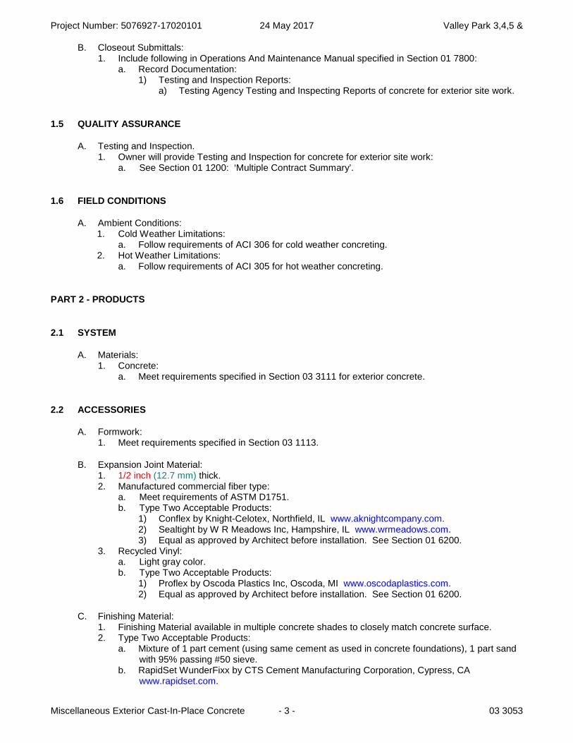
B. Closeout Submittals: 1. Include following in Operations And Maintenance Manual specified in Section 01 7800:
a. Record Documentation: 1) Testing and Inspection Reports:
a) Testing Agency Testing and Inspecting Reports of concrete for exterior site work.
1.5 QUALITY ASSURANCE
A. Testing and Inspection. 1. Owner will provide Testing and Inspection for concrete for exterior site work:
a. See Section 01 1200: ‘Multiple Contract Summary’.
1.6 FIELD CONDITIONS
A. Ambient Conditions: 1. Cold Weather Limitations:
a. Follow requirements of ACI 306 for cold weather concreting. 2. Hot Weather Limitations:
a. Follow requirements of ACI 305 for hot weather concreting.
PART 2 - PRODUCTS
2.1 SYSTEM
A. Materials: 1. Concrete:
a. Meet requirements specified in Section 03 3111 for exterior concrete.
2.2 ACCESSORIES
A. Formwork: 1. Meet requirements specified in Section 03 1113.
B. Expansion Joint Material: 1. 1/2 inch (12.7 mm) thick. 2. Manufactured commercial fiber type:
a. Meet requirements of ASTM D1751. b. Type Two Acceptable Products:
1) Conflex by Knight-Celotex, Northfield, IL www.aknightcompany.com.2) Sealtight by W R Meadows Inc, Hampshire, IL www.wrmeadows.com. 3) Equal as approved by Architect before installation. See Section 01 6200.
3. Recycled Vinyl: a. Light gray color. b. Type Two Acceptable Products:
1) Proflex by Oscoda Plastics Inc, Oscoda, MI www.oscodaplastics.com. 2) Equal as approved by Architect before installation. See Section 01 6200.
C. Finishing Material: 1. Finishing Material available in multiple concrete shades to closely match concrete surface. 2. Type Two Acceptable Products:
a. Mixture of 1 part cement (using same cement as used in concrete foundations), 1 part sand with 95% passing #50 sieve.
b. RapidSet WunderFixx by CTS Cement Manufacturing Corporation, Cypress, CA www.rapidset.com.
Project Number: 5076927-17020101 24 May 2017 Valley Park 3,4,5 &
Miscellaneous Exterior Cast-In-Place Concrete - 4 - 03 3053
c. Equal as approved by Architect before installation. See Section 01 6200.
PART 3 - EXECUTION
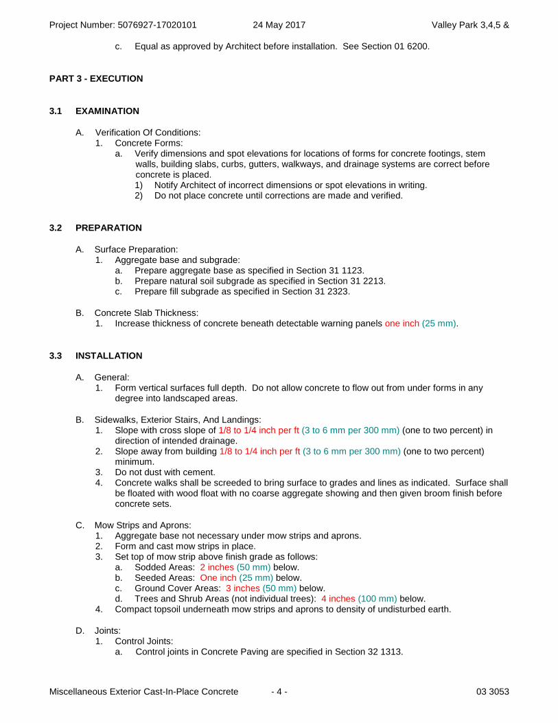
3.1 EXAMINATION
A. Verification Of Conditions: 1. Concrete Forms:
a. Verify dimensions and spot elevations for locations of forms for concrete footings, stem walls, building slabs, curbs, gutters, walkways, and drainage systems are correct before concrete is placed. 1) Notify Architect of incorrect dimensions or spot elevations in writing. 2) Do not place concrete until corrections are made and verified.
3.2 PREPARATION
A. Surface Preparation: 1. Aggregate base and subgrade:
a. Prepare aggregate base as specified in Section 31 1123. b. Prepare natural soil subgrade as specified in Section 31 2213. c. Prepare fill subgrade as specified in Section 31 2323.
B. Concrete Slab Thickness: 1. Increase thickness of concrete beneath detectable warning panels one inch (25 mm).
3.3 INSTALLATION
A. General: 1. Form vertical surfaces full depth. Do not allow concrete to flow out from under forms in any
degree into landscaped areas.
B. Sidewalks, Exterior Stairs, And Landings: 1. Slope with cross slope of 1/8 to 1/4 inch per ft (3 to 6 mm per 300 mm) (one to two percent) in
direction of intended drainage. 2. Slope away from building 1/8 to 1/4 inch per ft (3 to 6 mm per 300 mm) (one to two percent)
minimum. 3. Do not dust with cement. 4. Concrete walks shall be screeded to bring surface to grades and lines as indicated. Surface shall
be floated with wood float with no coarse aggregate showing and then given broom finish before concrete sets.
C. Mow Strips and Aprons: 1. Aggregate base not necessary under mow strips and aprons. 2. Form and cast mow strips in place. 3. Set top of mow strip above finish grade as follows:
a. Sodded Areas: 2 inches (50 mm) below. b. Seeded Areas: One inch (25 mm) below. c. Ground Cover Areas: 3 inches (50 mm) below. d. Trees and Shrub Areas (not individual trees): 4 inches (100 mm) below.
4. Compact topsoil underneath mow strips and aprons to density of undisturbed earth.
D. Joints: 1. Control Joints:
a. Control joints in Concrete Paving are specified in Section 32 1313.

Project Number: 5076927-17020101 24 May 2017 Valley Park 3,4,5 &
Miscellaneous Exterior Cast-In-Place Concrete - 5 - 03 3053
b. Depth of control joints shall be approximately one quarter of concrete slab thickness, but not less than one inch (25 mm).
c. Control joints to be hand tooled in sidewalks, curbs and gutters, mow strips, and aprons. d. Spacing On Center (+/-):
Sidewalks 4 feet to 6 feet 12 meters to 18 meters Curbs and Gutters 10 feet 3.0 meters Mow Strips 3 feet to 5 feet 0.90 meters to 1.50 meters Flat Drainage Structures 10 feet 3 meters Retaining Walls w/guardrails Align with postsRetaining Walls w/chain link fencing Align with posts
2. Expansion Joints: a. Expansion joints in Concrete Paving are specified in Section 32 1313. b. Install so top of expansion joint material is 1/4 inch (6 mm) below finished surface of
concrete. c. No expansion joint required between curbs and sidewalks parallel to curb. d. Provide expansion joints at ends of exterior site concrete elements that are perpendicular to
and terminate at curbs, building foundations or other concrete elements (i.e. sidewalks, mow strips, aprons).
e. Provide expansion joints between sidewalks that are parallel, and adjacent, to the storage building or main building.
f. Provide expansion joints around perimeter of concrete slab on grade at mechanical enclosure, around perimeter of slab on grade at dumpster enclosure and at top and bottom of exterior stairs.
g. Spacing On Center (+/-):
Sidewalks, Curbs and Gutters 40 feet to 100 feet 12 meters to 30 meters Mow Strips and Aprons 20 feet to 40 feet 6 meters to 12 meters Flat Drainage Structures 50 feet 15 meters Retaining Walls w/guardrails 36 feet 11 meters Retaining Walls w/chain link fencing 50 feet 15 meters
h. Seal expansion joints as specified in Section 07 9213 for following areas: 1) Between entryway slabs and building foundations. 2) Between sidewalks and building foundations. 3) Concrete retaining walls. 4) Within curbs and gutters. 5) Within flat drainage structures and at joints between flat drainage structures and other
concrete elements. i. Expansion joints are not required to be sealed for following areas:
1) Within aprons and where apron abuts sidewalks. 2) Within mow strips and where mow strip abuts building foundation and sidewalks. 3) Within sidewalks.
E. Finish: 1. Flatwork:
a. Curb, Gutter Sidewalks, Mow Strips, Flat Drainage Structures, Stairs, And Miscellaneous: 1) After completion of floating and troweling when excess moisture or surface sheen has
disappeared, complete surface finishing, as follows: a) Provide fine hair finish where grades are less than 6 percent 1-1/4 inch (32 mm). b) Provide rough hair finish where grades exceed 6 percent 1-1/4 inch (32 mm). c) Broom finish, by drawing broom across concrete surface, perpendicular to line of
traffic. Repeat operation if required to provide fine line texture acceptable to Architect. At curb and gutter, apply broom finish longitudinal to curb and gutter flowline.
d) On inclined slab surfaces, provide coarse, non-slip finish by scoring surface with stiff-bristled broom, perpendicular to line of traffic. At curb and gutter, apply broom finish longintudinal to curb and gutter flowline.
Project Number: 5076927-17020101 24 May 2017 Valley Park 3,4,5 &
Miscellaneous Exterior Cast-In-Place Concrete - 6 - 03 3053
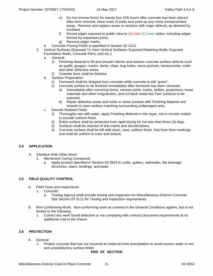
e) Do not remove forms for twenty four (24) hours after concrete has been placed. After form removal, clean ends of joints and point-up any minor honeycombed areas. Remove and replace areas or sections with major defects, as directed by Architect.
f) Round edges exposed to public view to 1/2 inch (13 mm) radius, including edges formed by expansion joints.
g) Remove edger marks. b. Concrete Paving Finish is specified in Section 32 1313.
2. Vertical Surfaces (Exposed To View Vertical Surfaces, Exposed Retaining Walls, Exposed Foundation Walls, Concrete Piers, and etc.): a. General:
1) Finishing Material to fill and smooth interior and exterior concrete surface defects such as spalls, gouges, cracks, dents, chips, bug holes, stone pockets, honeycombs, voids and other defective areas.
2) Chamfer lines shall be finished. b. Surface Preparation:
1) Formwork shall be stripped from concrete while concrete is still “green”. 2) Concrete surface to be finished immediately after formwork has been removed.
a) Immediately after removing forms, remove joints, marks, bellies, projections, loose materials and other irregularities, and cut back metal ties from surfaces to be exposed.
b) Repair defective areas and voids or stone pockets with Finishing Material and smooth to even surface matching surrounding undamaged area.
c. Smooth Rubbed Finish: 1) Thoroughly wet with water, apply Finishing Material in thin layer, rub in circular motion
to smooth uniform finish. 2) Entire surface shall be protected from rapid drying for not less than three (3) days. 3) Surfaces shall be cleaned of drip marks and discolorations. 4) Concrete surface shall be left with clean, neat, uniform finish, free from form markings
and shall be uniform in color and texture.
3.4 APPLICATION
A. Interface With Other Work: 1. Membrane Curing Compound:
a. Apply product specified in Section 03 3923 to curbs, gutters, sidewalks, flat drainage structures, stairs, landings, and pads.
3.5 FIELD QUALITY CONTROL
A. Field Tests and Inspections: 1. Concrete:
a. Testing Agency shall provide testing and inspection for Miscellaneous Exterior Concrete. See Section 03 3111 for Testing and Inspection requirements.
B. Non-Conforming Work: Non-conforming work as covered in the General Conditions applies, but is not limited to the following: 1. Correct any work found defective or not complying with contract document requirements at no
additional cost to the Owner.
3.6 PROTECTION
A. General: 1. Protect concrete that has not received its initial set from precipitation to avoid excess water in mix
and unsatisfactory surface finish. END OF SECTION
Project Number: 5076927-17020101 24 May 2017 Valley Park 3,4,5 &
Normal Weight Structural Concrete - 1 - 03 3111
SECTION 03 3111
NORMAL WEIGHT STRUCTURAL CONCRETE
PART 1 - GENERAL
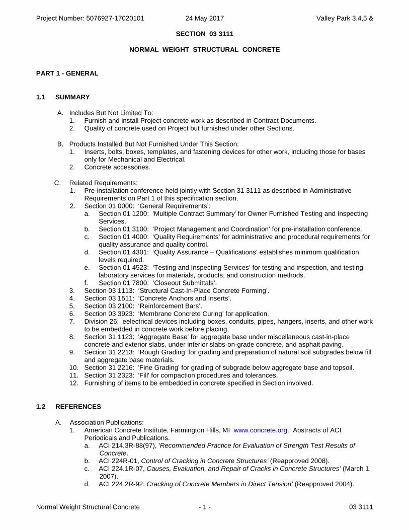
1.1 SUMMARY
A. Includes But Not Limited To: 1. Furnish and install Project concrete work as described in Contract Documents. 2. Quality of concrete used on Project but furnished under other Sections.
B. Products Installed But Not Furnished Under This Section: 1. Inserts, bolts, boxes, templates, and fastening devices for other work, including those for bases
only for Mechanical and Electrical. 2. Concrete accessories.
C. Related Requirements: 1. Pre-installation conference held jointly with Section 31 3111 as described in Administrative
Requirements on Part 1 of this specification section. 2. Section 01 0000: ‘General Requirements’:
a. Section 01 1200: 'Multiple Contract Summary' for Owner Furnished Testing and Inspecting Services.
b. Section 01 3100: ‘Project Management and Coordination’ for pre-installation conference. c. Section 01 4000: ‘Quality Requirements’ for administrative and procedural requirements for
quality assurance and quality control. d. Section 01 4301: ‘Quality Assurance – Qualifications’ establishes minimum qualification
levels required. e. Section 01 4523: ‘Testing and Inspecting Services’ for testing and inspection, and testing
laboratory services for materials, products, and construction methods. f. Section 01 7800: ‘Closeout Submittals’.
3. Section 03 1113: ‘Structural Cast-In-Place Concrete Forming’. 4. Section 03 1511: ‘Concrete Anchors and Inserts’. 5. Section 03 2100: ‘Reinforcement Bars’. 6. Section 03 3923: ‘Membrane Concrete Curing’ for application. 7. Division 26: eelectrical devices including boxes, conduits, pipes, hangers, inserts, and other work
to be embedded in concrete work before placing. 8. Section 31 1123: 'Aggregate Base' for aggregate base under miscellaneous cast-in-place
concrete and exterior slabs, under interior slabs-on-grade concrete, and asphalt paving. 9. Section 31 2213: ‘Rough Grading’ for grading and preparation of natural soil subgrades below fill
and aggregate base materials. 10. Section 31 2216: 'Fine Grading' for grading of subgrade below aggregate base and topsoil. 11. Section 31 2323: 'Fill' for compaction procedures and tolerances. 12. Furnishing of items to be embedded in concrete specified in Section involved.
1.2 REFERENCES
A. Association Publications: 1. American Concrete Institute, Farmington Hills, MI www.concrete.org. Abstracts of ACI
Periodicals and Publications. a. ACI 214.3R-88(97), 'Recommended Practice for Evaluation of Strength Test Results of
Concrete. b. ACI 224R-01, Control of Cracking in Concrete Structures’ (Reapproved 2008). c. ACI 224.1R-07, Causes, Evaluation, and Repair of Cracks in Concrete Structures’ (March 1,
2007). d. ACI 224.2R-92: Cracking of Concrete Members in Direct Tension’ (Reapproved 2004).
Project Number: 5076927-17020101 24 May 2017 Valley Park 3,4,5 &
Normal Weight Structural Concrete - 2 - 03 3111
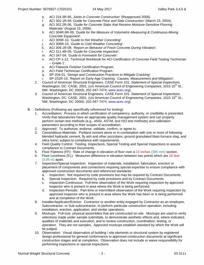
e. ACI 224.3R-95, Joints in Concrete Construction’ (Reapproved 2008). f. ACI 302.1R-04: Guide for Concrete Floor and Slab Construction’ (March 23, 2004). g. ACI 302.2R-06, ‘Guide for Concrete Slabs that Receive Moisture-Sensitive Flooring
Materials’ (August 15, 2006). h. ACI 304R.6R-09, 'Guide for the Measure of Volumetric-Measuring & Continuous-Mixing
Concrete Equipment'. i. ACI 305R-10, ‘Guide to Hot Weather Concreting’. j. ACI 306R-10, ‘Guide to Cold Weather Concreting’. k. ACI 309.1R-08, 'Report on Behavior of Fresh Concrete During Vibration'.l. ACI 311.4R-05, 'Guide for Concrete Inspection'. m. ACI 347-04, 'Guide to Formwork for Concrete'. n. ACI CP-1-12, ‘Technical Workbook for ACI Certification of Concrete Field Testing Technician
– Grade 1’. o. ACI Flatwork Finisher Certification Program. p. ACI Field Technician Certification Program. q. SP-204-01, ‘Design and Construction Practices to Mitigate Cracking'. r. SP-231R-10, ‘Report on Early-Age Cracking: Causes, Measurement and Mitigation'.
2. Council of American Structural Engineers. CASE Form 101: Statement of Special Inspections. Washington, DC: CASE, 2001. (c/o American Council of Engineering Companies, 1015 15
th St.,
NW, Washington, DC 20005; 202-347-7474; www.acec.org). 3. Council of American Structural Engineers. CASE Form 101: Statement of Special Inspections.
Washington, DC: CASE, 2001. (c/o American Council of Engineering Companies, 1015 15th St.,
NW, Washington, DC 20005; 202-347-7474; www.acec.org).
B. Definitions (Following are specifically referenced for testing): 1. Accreditation: Process in which certification of competency, authority, or credibility is presented.
Verify that laboratories have an appropriate quality management system and can properly perform certain test methods (e.g., ANSI, ASTM, and ISO test methods) and calibration parameters according to their scopes of accreditation.
2. Approved: To authorize, endorse, validate, confirm, or agree to. 3. Cementitious Materials: Portland cement alone or in combination with one or more of following:
blended hydraulic cement, fly ash and other pozzolans, ground granulated blast-furnace slag, and silica fume; subject to compliance with requirements.
4. Field Quality Control: Testing, Inspections, Special Testing and Special Inspections to assure compliance to Contract Documents.
5. Floor Flatness (FF): Rate of change in elevation of floor over a 12 inches (305 mm) section. 6. Floor Levelness (FL): Measures difference in elevation between two points which are 10 feet
(3.05 m) apart. 7. Inspection/Special Inspection: Inspection of materials, installation, fabrication, erection or
placement of components and connections requiring special expertise to ensure compliance with approved construction documents and referenced standards: a. Inspection: Not required by code provisions but may be required by Contract Documents. b. Special Inspection: Required by code provisions and by Contract Documents. c. Inspection-Continuous: Full-time observation of the Work requiring inspection by approved
inspector who is present in area where the Work is being performed. d. Inspection-Periodic: Part-time or intermittent observation of the Work requiring inspection by
approved inspector who is present in area where the Work has been or is being performed and at completion of the Work.
8. Installer/Applicator/Erector: Contractor or another entity engaged by Contractor as an employee, Subcontractor, or Sub-subcontractor, to perform particular construction operation, including installation, erection, application, and similar operations.
9. Mockups: Full-size, physical assemblies that are constructed on-site. Mockups are used to verify selections made under sample submittals, to demonstrate aesthetic effects and, where indicated, qualities of materials and execution, and to review construction, coordination, testing, or operation. They are not samples. Approved mockups establish standard by which the Work will be judged.
10. Observation: Visual observation of building / site elements or structural system by registered design professional for general conformance to approved construction documents at significant construction stages and at completion. Observation does not include or waive responsibility for performing inspections or special inspections.
Project Number: 5076927-17020101 24 May 2017 Valley Park 3,4,5 &
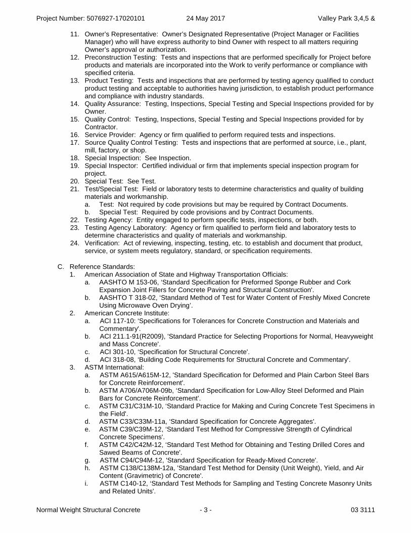
Normal Weight Structural Concrete - 3 - 03 3111
11. Owner’s Representative: Owner’s Designated Representative (Project Manager or Facilities Manager) who will have express authority to bind Owner with respect to all matters requiring Owner’s approval or authorization.
12. Preconstruction Testing: Tests and inspections that are performed specifically for Project before products and materials are incorporated into the Work to verify performance or compliance with specified criteria.
13. Product Testing: Tests and inspections that are performed by testing agency qualified to conduct product testing and acceptable to authorities having jurisdiction, to establish product performance and compliance with industry standards.
14. Quality Assurance: Testing, Inspections, Special Testing and Special Inspections provided for by Owner.
15. Quality Control: Testing, Inspections, Special Testing and Special Inspections provided for by Contractor.
16. Service Provider: Agency or firm qualified to perform required tests and inspections. 17. Source Quality Control Testing: Tests and inspections that are performed at source, i.e., plant,
mill, factory, or shop. 18. Special Inspection: See Inspection. 19. Special Inspector: Certified individual or firm that implements special inspection program for
project. 20. Special Test: See Test. 21. Test/Special Test: Field or laboratory tests to determine characteristics and quality of building
materials and workmanship. a. Test: Not required by code provisions but may be required by Contract Documents. b. Special Test: Required by code provisions and by Contract Documents.
22. Testing Agency: Entity engaged to perform specific tests, inspections, or both. 23. Testing Agency Laboratory: Agency or firm qualified to perform field and laboratory tests to
determine characteristics and quality of materials and workmanship. 24. Verification: Act of reviewing, inspecting, testing, etc. to establish and document that product,
service, or system meets regulatory, standard, or specification requirements.
C. Reference Standards: 1. American Association of State and Highway Transportation Officials:
a. AASHTO M 153-06, ‘Standard Specification for Preformed Sponge Rubber and Cork Expansion Joint Fillers for Concrete Paving and Structural Construction'.
b. AASHTO T 318-02, ‘Standard Method of Test for Water Content of Freshly Mixed Concrete Using Microwave Oven Drying’.
2. American Concrete Institute: a. ACI 117-10: ‘Specifications for Tolerances for Concrete Construction and Materials and
Commentary'. b. ACI 211.1-91(R2009), 'Standard Practice for Selecting Proportions for Normal, Heavyweight
and Mass Concrete'. c. ACI 301-10, ‘Specification for Structural Concrete'. d. ACI 318-08, ‘Building Code Requirements for Structural Concrete and Commentary'.
3. ASTM International: a. ASTM A615/A615M-12, 'Standard Specification for Deformed and Plain Carbon Steel Bars
for Concrete Reinforcement'. b. ASTM A706/A706M-09b, ‘Standard Specification for Low-Alloy Steel Deformed and Plain
Bars for Concrete Reinforcement’. c. ASTM C31/C31M-10, ‘Standard Practice for Making and Curing Concrete Test Specimens in
the Field'. d. ASTM C33/C33M-11a, ‘Standard Specification for Concrete Aggregates'. e. ASTM C39/C39M-12, ‘Standard Test Method for Compressive Strength of Cylindrical
Concrete Specimens'. f. ASTM C42/C42M-12, ‘Standard Test Method for Obtaining and Testing Drilled Cores and
Sawed Beams of Concrete'. g. ASTM C94/C94M-12, 'Standard Specification for Ready-Mixed Concrete'. h. ASTM C138/C138M-12a, 'Standard Test Method for Density (Unit Weight), Yield, and Air
Content (Gravimetric) of Concrete'. i. ASTM C140-12, ‘Standard Test Methods for Sampling and Testing Concrete Masonry Units
and Related Units'.
Project Number: 5076927-17020101 24 May 2017 Valley Park 3,4,5 &
Normal Weight Structural Concrete - 4 - 03 3111
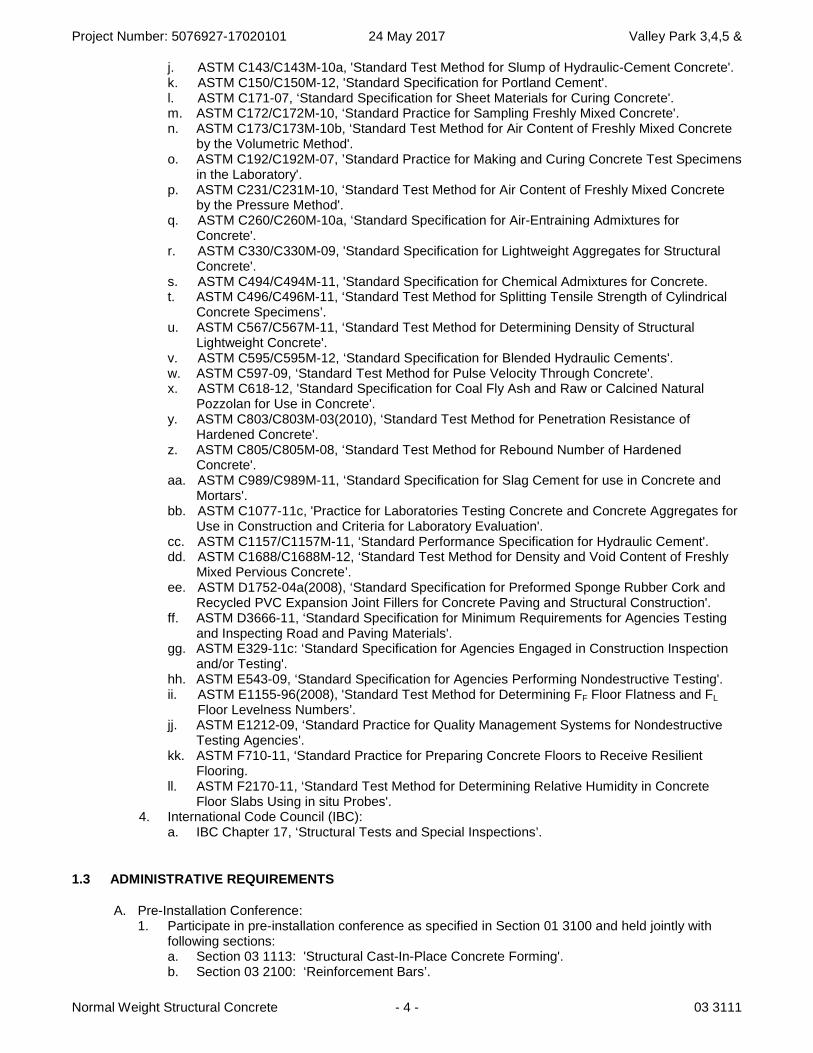
j. ASTM C143/C143M-10a, 'Standard Test Method for Slump of Hydraulic-Cement Concrete'. k. ASTM C150/C150M-12, 'Standard Specification for Portland Cement'. l. ASTM C171-07, ‘Standard Specification for Sheet Materials for Curing Concrete'. m. ASTM C172/C172M-10, ‘Standard Practice for Sampling Freshly Mixed Concrete'. n. ASTM C173/C173M-10b, ‘Standard Test Method for Air Content of Freshly Mixed Concrete
by the Volumetric Method'. o. ASTM C192/C192M-07, ’Standard Practice for Making and Curing Concrete Test Specimens
in the Laboratory'. p. ASTM C231/C231M-10, ‘Standard Test Method for Air Content of Freshly Mixed Concrete
by the Pressure Method'. q. ASTM C260/C260M-10a, ‘Standard Specification for Air-Entraining Admixtures for
Concrete'. r. ASTM C330/C330M-09, 'Standard Specification for Lightweight Aggregates for Structural
Concrete'. s. ASTM C494/C494M-11, 'Standard Specification for Chemical Admixtures for Concrete. t. ASTM C496/C496M-11, ‘Standard Test Method for Splitting Tensile Strength of Cylindrical
Concrete Specimens’. u. ASTM C567/C567M-11, ‘Standard Test Method for Determining Density of Structural
Lightweight Concrete'. v. ASTM C595/C595M-12, ‘Standard Specification for Blended Hydraulic Cements'. w. ASTM C597-09, ‘Standard Test Method for Pulse Velocity Through Concrete'. x. ASTM C618-12, 'Standard Specification for Coal Fly Ash and Raw or Calcined Natural
Pozzolan for Use in Concrete'. y. ASTM C803/C803M-03(2010), ‘Standard Test Method for Penetration Resistance of
Hardened Concrete'. z. ASTM C805/C805M-08, ‘Standard Test Method for Rebound Number of Hardened
Concrete'. aa. ASTM C989/C989M-11, ‘Standard Specification for Slag Cement for use in Concrete and
Mortars'. bb. ASTM C1077-11c, 'Practice for Laboratories Testing Concrete and Concrete Aggregates for
Use in Construction and Criteria for Laboratory Evaluation'. cc. ASTM C1157/C1157M-11, ‘Standard Performance Specification for Hydraulic Cement'. dd. ASTM C1688/C1688M-12, ‘Standard Test Method for Density and Void Content of Freshly
Mixed Pervious Concrete’. ee. ASTM D1752-04a(2008), ‘Standard Specification for Preformed Sponge Rubber Cork and
Recycled PVC Expansion Joint Fillers for Concrete Paving and Structural Construction'. ff. ASTM D3666-11, ‘Standard Specification for Minimum Requirements for Agencies Testing
and Inspecting Road and Paving Materials'. gg. ASTM E329-11c: ‘Standard Specification for Agencies Engaged in Construction Inspection
and/or Testing'. hh. ASTM E543-09, ‘Standard Specification for Agencies Performing Nondestructive Testing'. ii. ASTM E1155-96(2008), 'Standard Test Method for Determining FF Floor Flatness and FL
Floor Levelness Numbers’. jj. ASTM E1212-09, ‘Standard Practice for Quality Management Systems for Nondestructive
Testing Agencies'. kk. ASTM F710-11, ‘Standard Practice for Preparing Concrete Floors to Receive Resilient
Flooring. ll. ASTM F2170-11, ‘Standard Test Method for Determining Relative Humidity in Concrete
Floor Slabs Using in situ Probes'. 4. International Code Council (IBC):
a. IBC Chapter 17, ‘Structural Tests and Special Inspections’.
1.3 ADMINISTRATIVE REQUIREMENTS
A. Pre-Installation Conference: 1. Participate in pre-installation conference as specified in Section 01 3100 and held jointly with
following sections: a. Section 03 1113: 'Structural Cast-In-Place Concrete Forming'. b. Section 03 2100: ‘Reinforcement Bars’.

Project Number: 5076927-17020101 24 May 2017 Valley Park 3,4,5 &
Normal Weight Structural Concrete - 5 - 03 3111
c. Section 03 3053: 'Miscellaneous Exterior Cast-In-Place Concrete'. Section 26 0526: 'Grounding And Bonding For Electrical Systems'.
2. Schedule pre-installation conference prior to placing of footings, installation of foundation forms and reinforcing steel, and installation of anchors, dowels, inserts, and block outs in foundation walls and slabs:
3. In addition to agenda items specified in Section 01 3100, review following: a. Installation scheduling, coordination, placement of concrete, and placement of items
installed in and under floor slab. b. Review requirements for preparation of subgrade. c. Review aggregate base requirements. d. Review formwork requirements. e. Review approved mix design requirements and use of admixtures. f. Review reinforcing steel submittals. g. Review placement, finishing, and curing of concrete including cold and hot weather
requirements. h. Review jointing requirements and joint layout. i. Review concrete slab tolerances and corrective measures if tolerances not met. j. Review safety issues. k. Review Section 01 4523 for Testing and Inspection administrative requirements and
responsibilities and Field Quality Control tests and inspections required of this section. 1) Review frequency of testing and inspections.
B. Scheduling: 1. Notify Testing Agency and Architect twenty four (24) hours minimum before placing concrete.
1.4 SUBMITTALS
A. Action Submittals: 1. Shop Drawings:
a. Show dimensioned locations of anchor bolts for hold-down anchors and columns. b. Show reinforcement and all necessary bending diagrams and reinforcing steel list, and
construction joint locations. c. Provide bar schedules and bending details. d. Reinforced concrete walls shall be shown in scale elevation (scale at least one quarter inch
to one foot). Details shall be in accordance with ACI rules. e. Show all formwork for concrete surfaces which are to remain exposed in the finished work.
B. Informational Submittals: 1. Certificates:
a. Installers: 1) Certification for National Ready Mixed Concrete Association (NRMCA). 2) Certification for ACI-certified Flatwork Finishers and Technicians.
2. Design Data: a. Mix Design:
1) Furnish proposed mix design to Architect for review prior to commencement of Work. a) Include density (unit weight) and void content determined per ASTM
C1688/C1688M for fresh mixed properties and per ASTM C140 for hardened concrete properties.
b) Mix design shall show proposed admixture, amount, usage instructions, and justification for proposed use.
b. Ready-Mix Supplier: 1) Require mix plant to furnish delivery ticket for each batch of concrete. Keep delivery
tickets at job-site for use of Owner or his representatives. Tickets shall show following: a) Name of ready-mix batch plant. b) Serial number of ticket. c) Date and truck number. d) Name of Contractor. e) Name and location of Project.
Project Number: 5076927-17020101 24 May 2017 Valley Park 3,4,5 &
Normal Weight Structural Concrete - 6 - 03 3111
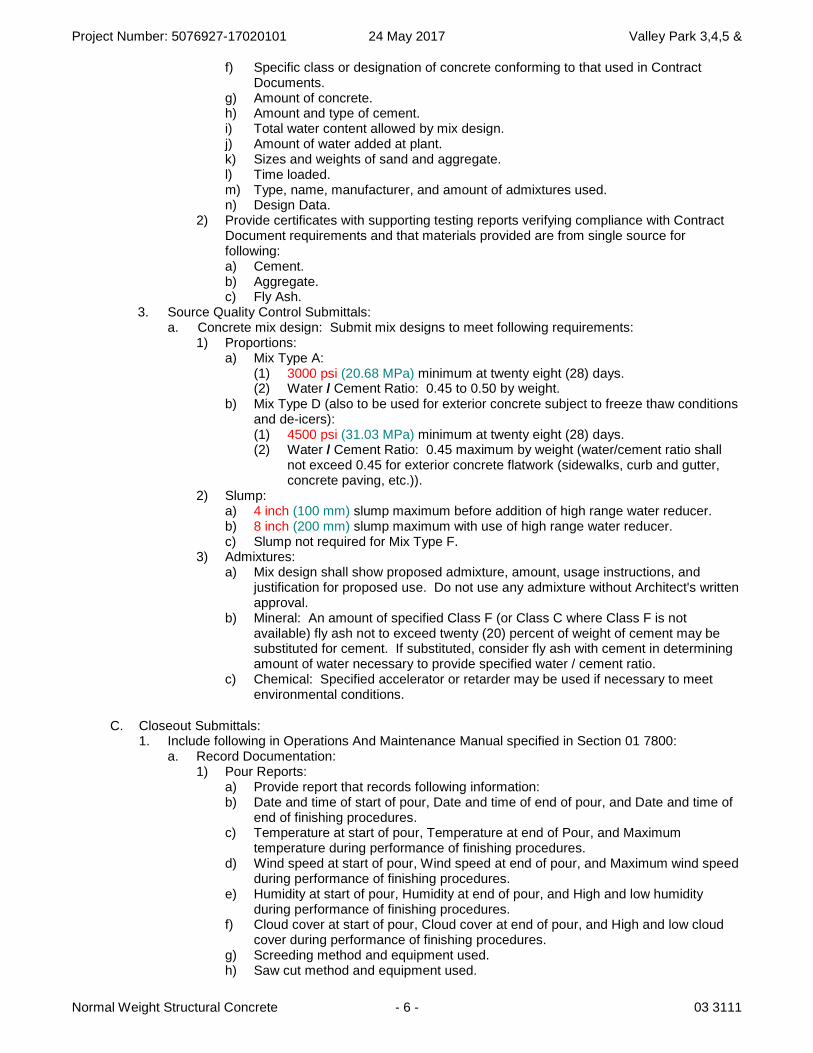
f) Specific class or designation of concrete conforming to that used in Contract Documents.
g) Amount of concrete. h) Amount and type of cement. i) Total water content allowed by mix design. j) Amount of water added at plant. k) Sizes and weights of sand and aggregate. l) Time loaded. m) Type, name, manufacturer, and amount of admixtures used. n) Design Data.
2) Provide certificates with supporting testing reports verifying compliance with Contract Document requirements and that materials provided are from single source for following: a) Cement. b) Aggregate. c) Fly Ash.
3. Source Quality Control Submittals: a. Concrete mix design: Submit mix designs to meet following requirements:
1) Proportions: a) Mix Type A:
(1) 3000 psi (20.68 MPa) minimum at twenty eight (28) days. (2) Water / Cement Ratio: 0.45 to 0.50 by weight.
b) Mix Type D (also to be used for exterior concrete subject to freeze thaw conditions and de-icers): (1) 4500 psi (31.03 MPa) minimum at twenty eight (28) days. (2) Water / Cement Ratio: 0.45 maximum by weight (water/cement ratio shall
not exceed 0.45 for exterior concrete flatwork (sidewalks, curb and gutter, concrete paving, etc.)).
2) Slump: a) 4 inch (100 mm) slump maximum before addition of high range water reducer. b) 8 inch (200 mm) slump maximum with use of high range water reducer. c) Slump not required for Mix Type F.
3) Admixtures: a) Mix design shall show proposed admixture, amount, usage instructions, and
justification for proposed use. Do not use any admixture without Architect's written approval.
b) Mineral: An amount of specified Class F (or Class C where Class F is not available) fly ash not to exceed twenty (20) percent of weight of cement may be substituted for cement. If substituted, consider fly ash with cement in determining amount of water necessary to provide specified water / cement ratio.
c) Chemical: Specified accelerator or retarder may be used if necessary to meet environmental conditions.
C. Closeout Submittals: 1. Include following in Operations And Maintenance Manual specified in Section 01 7800:
a. Record Documentation: 1) Pour Reports:
a) Provide report that records following information: b) Date and time of start of pour, Date and time of end of pour, and Date and time of
end of finishing procedures. c) Temperature at start of pour, Temperature at end of Pour, and Maximum
temperature during performance of finishing procedures. d) Wind speed at start of pour, Wind speed at end of pour, and Maximum wind speed
during performance of finishing procedures. e) Humidity at start of pour, Humidity at end of pour, and High and low humidity
during performance of finishing procedures. f) Cloud cover at start of pour, Cloud cover at end of pour, and High and low cloud
cover during performance of finishing procedures. g) Screeding method and equipment used. h) Saw cut method and equipment used.

Project Number: 5076927-17020101 24 May 2017 Valley Park 3,4,5 &
Normal Weight Structural Concrete - 7 - 03 3111
2) Testing and Inspection Reports: a) Testing Agency Testing and Inspecting Reports of concrete.
1.5 QUALITY ASSURANCE
A. Qualifications: Requirements of Section 01 4301 applies, but is not limited to following: 1. Installers and Installation Supervisor:
a. ACI-certified Flatwork Technician and Finisher and a supervisor who is an ACI-certified Concrete Flatwork Technician.
2. Ready-Mix Supplier: a. Comply with ASTM C94/C94M requirements and be certified according to NRMCA's
'Certification of Ready Mixed Concrete Production Facilities'. 3. Testing Agencies:
a. Independent agency qualified according to ASTM C1077 and ASTM E329. 1) Personnel conducting field tests shall be qualified as ACI Concrete Field Testing
Technicians, Grade I according to ACI CP-1 or equivalent certification program. 2) Personnel performing laboratory tests shall be ACI-certified Concrete Strength Testing
Technician and Concrete Laboratory Testing Technician - Grade I. Testing Agency laboratory supervisor shall be ACI-certified Concrete Laboratory Testing Technician - Grade II.
B. Testing and Inspection: 1. Owner will provide Testing and Inspection on concrete:
a. See Section 01 1200: ‘Multiple Contract Summary’.
1.6 DELIVERY, STORAGE, AND HANDLING
A. Delivery And Acceptance Requirements: 1. Expansion Filler Material:
a. Deliver materials to site in manufacturer's original, unopened containers and packaging, with labels clearly identifying product name and manufacturer.
B. Storage And Handling Requirements: 1. Expansion Filler Material:
a. Store materials in a clean, dry area in accordance with manufacturer's instructions. b. Protect materials during handling and application to prevent damage.
PART 2 - PRODUCTS
2.1 SYSTEM
A. Manufacturers: 1. Manufacturer Contact List:
a. BASF Admixtures, Cleveland, OH www.basf-admixtures.com. b. Bonsal American, Charlotte, NC www.bonsal.com. c. Dayton Superior Specialty Chemicals, Kansas City, KS www.daytonsuperiorchemical.com. d. Euclid Chemical Company, Cleveland, OH www.euclidchemical.com. e. Fritz-Pak Concrete Admixtures, Dallas, TX www.fritzpak.com. f. Grace Construction Products, Cambridge, MA www.graceconstruction.com and Grace
Canada Inc, Ajax, ON (905) 683-8561. g. L & M Construction Chemicals, Omaha, NE www.lmcc.com. h. Larsen Weldcrete by Larsen Products Corp, Rockville, MD www.larsenproducts.com. i. Sika Corporation, Lyndhurst, NJ www.sikaconstruction.com and Sika Canada, Pointe
Claire, QC www.sika.ca. j. Sonneborn / BASF Building Systems, Shakopee, MN www.chemrex.com.

Project Number: 5076927-17020101 24 May 2017 Valley Park 3,4,5 &
Normal Weight Structural Concrete - 8 - 03 3111
k. Unitex, Kansas City, MO www.unitex-chemicals.com. l. U S Mix Products Co, Denver, CO www.usspec.com. m. W R Meadows, Hampshire, IL www.wrmeadows.com.
B. Performance: 1. Design Criteria: Conform to requirements of ASTM C94/C94M unless specified otherwise:
a. Floor Slab for interior concrete slabs: 1) Class 1 Floor:
a) Anticipated type of traffic: exposed surface – foot traffic. b) Special considerations: Uniform finish, nonslip aggregated in specific areas,
curing. c) Final finish: Normal steel-troweled finish, nonslip finish where required.
2) Meet requirements of ASTM C1116/C1116M, Type III. 3) Alkali Resistance: Alkali proof.
2. Capacities: a. For testing purposes, following concrete strengths are required:
1) At 7 days: 60 percent minimum of 28 day strengths. 2) At 28 days: 100 percent minimum of 28 day strengths.
C. Materials: 1. Table One:
Portland Cement / Blended Hydraulic Cement Equivalencies
ASTM C150/C150M (Low Alkali) ASTM C595/C595M ASTM C1157/C1157M
Type II IP (MS) MS
2. Hydraulic Cement: Meet requirements of ASTM C150/C150M, Type II. a. Meet requirements of ASTM C595/C595M, Type IP(MS) b. Meet requirements of ASTM C1157/C1157M, Type MS.
3. Aggregates: a. General:
1) Submit a letter on quarry’s letterhead that certifies all aggregate for concrete complies with the requirements of this section. Material certificates which are submitted shall be signed by both the materials producer and the contractor, certifying that materials comply with or exceed requirements specified herein to the Architect, Civil and Structural Engineering Consultant and the Independent Testing Laboratory for review and approval.
2) Aggregates for all concrete shall come from a quarry that is DOT approved and meets or exceeds durability Class I aggregate. The quarry shall submit a letter to Engineer that certifies that all aggregate complies with DOT requirements for durability. Aggregate not meeting DOT durability requirements shall not be used.
b. Coarse: 1) Meet requirements of ASTM C33/C33M or nonconforming aggregate that by test or
actual service produces concrete of required strength and conforms to local governing codes.
2) Aggregate shall be uniformly graded by weight as follows:
a) Table Two: Flat Work, Size No. 67. Sieve Percent Passing Sieve Percent Passing One Inch 100 25 mm 100 3/4 Inch 90 - 100 19 mm 90 - 100 3/8 Inch 20 - 55 9 mm 20 - 55 No. 4 0 - 10 4.75 mm 0 - 10 No. 8 0 - 5 2.36 mm 0 - 5
b) Table Three: All Other, Size No. 57. Sieve Percent Passing Sieve Percent Passing 1-1/2 Inch 100 38 mm 100
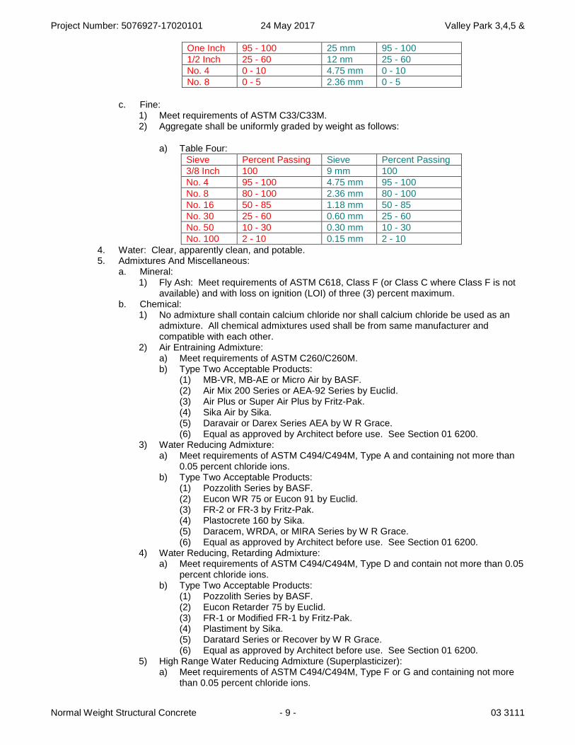
Project Number: 5076927-17020101 24 May 2017 Valley Park 3,4,5 &
Normal Weight Structural Concrete - 9 - 03 3111
One Inch 95 - 100 25 mm 95 - 100 1/2 Inch 25 - 60 12 nm 25 - 60 No. 4 0 - 10 4.75 mm 0 - 10 No. 8 0 - 5 2.36 mm 0 - 5
c. Fine: 1) Meet requirements of ASTM C33/C33M. 2) Aggregate shall be uniformly graded by weight as follows:
a) Table Four: Sieve Percent Passing Sieve Percent Passing 3/8 Inch 100 9 mm 100 No. 4 95 - 100 4.75 mm 95 - 100 No. 8 80 - 100 2.36 mm 80 - 100 No. 16 50 - 85 1.18 mm 50 - 85 No. 30 25 - 60 0.60 mm 25 - 60 No. 50 10 - 30 0.30 mm 10 - 30 No. 100 2 - 10 0.15 mm 2 - 10
4. Water: Clear, apparently clean, and potable. 5. Admixtures And Miscellaneous:
a. Mineral: 1) Fly Ash: Meet requirements of ASTM C618, Class F (or Class C where Class F is not
available) and with loss on ignition (LOI) of three (3) percent maximum. b. Chemical:
1) No admixture shall contain calcium chloride nor shall calcium chloride be used as an admixture. All chemical admixtures used shall be from same manufacturer and compatible with each other.
2) Air Entraining Admixture: a) Meet requirements of ASTM C260/C260M. b) Type Two Acceptable Products:
(1) MB-VR, MB-AE or Micro Air by BASF. (2) Air Mix 200 Series or AEA-92 Series by Euclid. (3) Air Plus or Super Air Plus by Fritz-Pak. (4) Sika Air by Sika. (5) Daravair or Darex Series AEA by W R Grace. (6) Equal as approved by Architect before use. See Section 01 6200.
3) Water Reducing Admixture: a) Meet requirements of ASTM C494/C494M, Type A and containing not more than
0.05 percent chloride ions. b) Type Two Acceptable Products:
(1) Pozzolith Series by BASF. (2) Eucon WR 75 or Eucon 91 by Euclid. (3) FR-2 or FR-3 by Fritz-Pak. (4) Plastocrete 160 by Sika. (5) Daracem, WRDA, or MIRA Series by W R Grace. (6) Equal as approved by Architect before use. See Section 01 6200.
4) Water Reducing, Retarding Admixture: a) Meet requirements of ASTM C494/C494M, Type D and contain not more than 0.05
percent chloride ions. b) Type Two Acceptable Products:
(1) Pozzolith Series by BASF. (2) Eucon Retarder 75 by Euclid. (3) FR-1 or Modified FR-1 by Fritz-Pak. (4) Plastiment by Sika. (5) Daratard Series or Recover by W R Grace. (6) Equal as approved by Architect before use. See Section 01 6200.
5) High Range Water Reducing Admixture (Superplasticizer): a) Meet requirements of ASTM C494/C494M, Type F or G and containing not more
than 0.05 percent chloride ions.
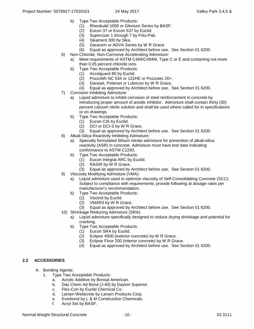
Project Number: 5076927-17020101 24 May 2017 Valley Park 3,4,5 &
Normal Weight Structural Concrete - 10 - 03 3111
b) Type Two Acceptable Products: (1) Rheobuild 1000 or Glenium Series by BASF. (2) Eucon 37 or Eucon 537 by Euclid. (3) Supercizer 1 through 7 by Fritz-Pak. (4) Sikament 300 by Sika. (5) Daracem or ADVA Series by W R Grace. (6) Equal as approved by Architect before use. See Section 01 6200.
6) Non-Chloride, Non-Corrosive Accelerating Admixture: a) Meet requirements of ASTM C494/C494M, Type C or E and containing not more
than 0.05 percent chloride ions. b) Type Two Acceptable Products:
(1) Accelguard 80 by Euclid. (2) Pozzolith NC 534 or 122HE or Pozzutec 20+. (3) Daraset, Polarset or Lubricon by W R Grace. (4) Equal as approved by Architect before use. See Section 01 6200.
7) Corrosion Inhibiting Admixture: a) Liquid admixture to inhibit corrosion of steel reinforcement in concrete by
introducing proper amount of anodic inhibitor. Admixture shall contain thirty (30) percent calcium nitrite solution and shall be used where called for in specifications or on drawings.
b) Type Two Acceptable Products: (1) Eucon CIA by Euclid. (2) DCI or DCI-S by W R Grace. (3) Equal as approved by Architect before use. See Section 01 6200.
8) Alkali-Silica Reactivity Inhibiting Admixture: a) Specially formulated lithium nitrate admixture for prevention of alkali-silica
reactivity (ASR) in concrete. Admixture must have test data indicating conformance to ASTM C1293.
b) Type Two Acceptable Products: (1) Eucon Integral ARC by Euclid. (2) RASIR by W R Grace. (3) Equal as approved by Architect before use. See Section 01 6200.
9) Viscosity Modifying Admixture (VMA): a) Liquid admixture used to optimize viscosity of Self-Consolidating Concrete (SCC).
Subject to compliance with requirements, provide following at dosage rates per manufacturer’s recommendation.
b) Type Two Acceptable Products: (1) Visctrol by Euclid. (2) VMAR3 by W R Grace. (3) Equal as approved by Architect before use. See Section 01 6200.
10) Shrinkage Reducing Admixture (SRA): a) Liquid admixture specifically designed to reduce drying shrinkage and potential for
cracking. b) Type Two Acceptable Products:
(1) Eucon SRA by Euclid. (2) Eclipse 4500 (exterior concrete) by W R Grace. (3) Eclipse Floor 200 (interior concrete) by W R Grace. (4) Equal as approved by Architect before use. See Section 01 6200.
2.2 ACCESSORIES
A. Bonding Agents: 1. Type Two Acceptable Products:
a. Acrylic Additive by Bonsal American. b. Day Chem Ad Bond (J-40) by Dayton Superior. c. Flex-Con by Euclid Chemical Co. d. Larsen Weldcrete by Larsen Products Corp. e. Everbond by L & M Construction Chemicals. f. Acryl Set by BASF.
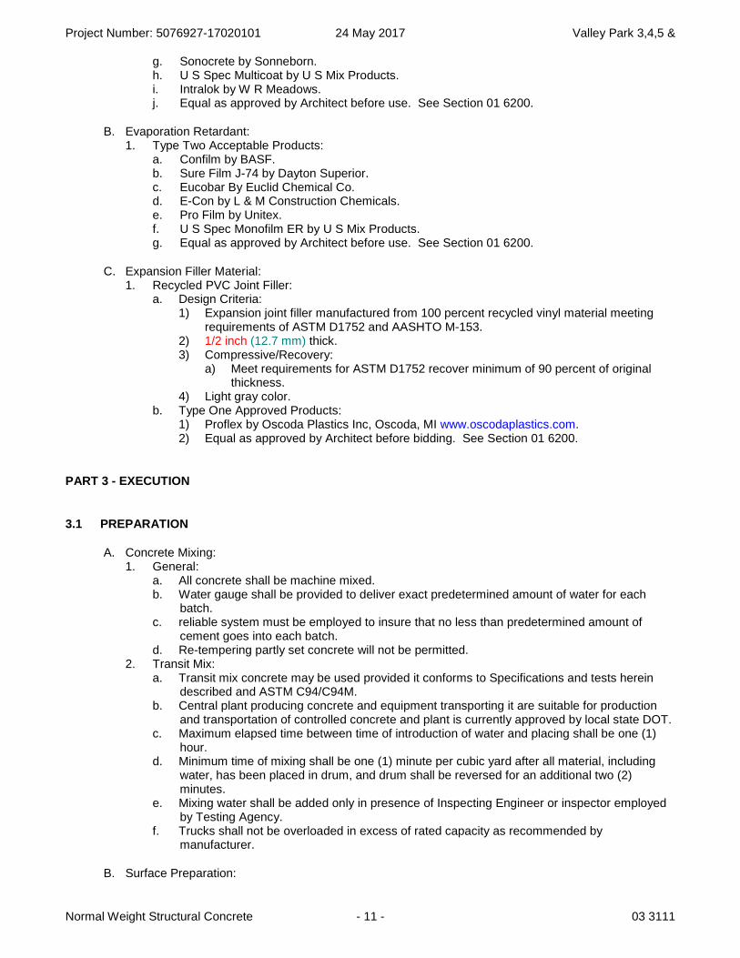
Project Number: 5076927-17020101 24 May 2017 Valley Park 3,4,5 &
Normal Weight Structural Concrete - 11 - 03 3111
g. Sonocrete by Sonneborn. h. U S Spec Multicoat by U S Mix Products. i. Intralok by W R Meadows. j. Equal as approved by Architect before use. See Section 01 6200.
B. Evaporation Retardant: 1. Type Two Acceptable Products:
a. Confilm by BASF. b. Sure Film J-74 by Dayton Superior. c. Eucobar By Euclid Chemical Co. d. E-Con by L & M Construction Chemicals. e. Pro Film by Unitex. f. U S Spec Monofilm ER by U S Mix Products. g. Equal as approved by Architect before use. See Section 01 6200.
C. Expansion Filler Material: 1. Recycled PVC Joint Filler:
a. Design Criteria: 1) Expansion joint filler manufactured from 100 percent recycled vinyl material meeting
requirements of ASTM D1752 and AASHTO M-153. 2) 1/2 inch (12.7 mm) thick. 3) Compressive/Recovery:
a) Meet requirements for ASTM D1752 recover minimum of 90 percent of original thickness.
4) Light gray color. b. Type One Approved Products:
1) Proflex by Oscoda Plastics Inc, Oscoda, MI www.oscodaplastics.com. 2) Equal as approved by Architect before bidding. See Section 01 6200.
PART 3 - EXECUTION
3.1 PREPARATION
A. Concrete Mixing: 1. General:
a. All concrete shall be machine mixed. b. Water gauge shall be provided to deliver exact predetermined amount of water for each
batch. c. reliable system must be employed to insure that no less than predetermined amount of
cement goes into each batch. d. Re-tempering partly set concrete will not be permitted.
2. Transit Mix: a. Transit mix concrete may be used provided it conforms to Specifications and tests herein
described and ASTM C94/C94M. b. Central plant producing concrete and equipment transporting it are suitable for production
and transportation of controlled concrete and plant is currently approved by local state DOT. c. Maximum elapsed time between time of introduction of water and placing shall be one (1)
hour. d. Minimum time of mixing shall be one (1) minute per cubic yard after all material, including
water, has been placed in drum, and drum shall be reversed for an additional two (2) minutes.
e. Mixing water shall be added only in presence of Inspecting Engineer or inspector employed by Testing Agency.
f. Trucks shall not be overloaded in excess of rated capacity as recommended by manufacturer.
B. Surface Preparation:

Project Number: 5076927-17020101 24 May 2017 Valley Park 3,4,5 &
Normal Weight Structural Concrete - 12 - 03 3111
1. Inserts, bolts, boxes, templates, pipes, conduits, and other accessories required by Divisions 22, 23, and 26 shall be installed and inspected before placing concrete.
2. Install inserts, bolts, boxes, templates, pipes, conduits, and other accessories furnished under other Sections to be installed as part of work of this Section. a. Tie anchor bolts for hold-down anchors and columns securely to reinforcing steel.
C. Removal: 1. Remove water and debris from space to be placed.
3.2 INSTALLATION
A. Special Techniques: 1. Cold Weather Concreting Procedures:
a. General Requirements: 1) Materials and equipment required for heating and protection of concrete shall be
approved and available at Project site before beginning cold weather concreting. a) Heating devices used to maintain specified temperatures shall have baffle plate
above, of sufficient size, and sand bed below, in order to distribute heat. b) Heating devices shall be so operated that temperature of air immediately below
slab forms shall not exceed 100 deg F (37.8 deg C). Provide sufficient and suitable thermometers to verify compliance.
2) Forms, reinforcement, metallic embedments, and fillers shall be free from snow, ice, and frost. Surfaces that will be in contact with newly placed concrete, including sub-grade materials, shall be 35 deg F (2 deg C) minimum at time of concrete placement.
3) Thaw sub-grade 6 inches (150 mm) deep minimum before beginning concrete placement. If necessary, re-compact thawed material.
4) Use no frozen materials or materials containing ice. 5) No salt or other chemical may be used for such protection. 6) Only specified non-corrosive non-chloride accelerator shall be used. Calcium chloride,
thiocyanates or admixtures containing more than 0.05 percent chloride ions are not permitted.
b. Requirements When Average twenty four (24) Hour Temperature, midnight to midnight, Is Below 40 deg F (4 deg C): 1) Temperature of concrete as placed and maintained shall be 55 deg F (13 deg C)
minimum and 75 deg F (27 deg C) maximum. 2) Heat concrete for seventy two (72) hours minimum after placing if regular cement is
used; for 48 hours if high early strength cement is used; or longer if determined necessary by Architect. a) During this period, maintain concrete surface temperature between 55 and 75 deg
F (13 and 27 deg C). 3) Vent flue gases from combustion heating units to outside of enclosure to prevent
carbonation of concrete surface. 4) Prevent concrete from drying during heating period. Maintain housing, insulation,
covering, and other protection twenty four (24) hours after heat is discontinued. 5) After heating period, if temperature falls below 32 deg F (0 deg C), protect concrete
from freezing until strength of 2000 psi (13.79 MPa) minimum is achieved. a) Protect flatwork exposed to melting snow or rain during day and freezing during
night from freezing until strength of 3500 psi (24.13 MPa) minimum is achieved. c. Requirements When Average twenty four (24) Hour Temperature, midnight to midnight, Is
Above 40 deg F (4 deg C), but when temperature falls below 32 deg F (0 deg C): 1) Protect concrete from freezing for seventy two (72) hours after placing, or until strength
of 2000 psi (13.79 MPa) is achieved, whichever is longer. 2) Protect flatwork exposed to melting snow or rain during day and freezing during night
from freezing until strength of 3500 psi (24.13 MPa) minimum is achieved. d. Protect soil supporting concrete footings from freezing under any circumstances.
2. Hot Weather Concreting Procedures: a. Maximum concrete temperature allowed is 90 deg F (32 deg C) in hot weather. b. Cool aggregate and subgrades by sprinkling. c. Avoid cement over 140 deg F (60 deg C).
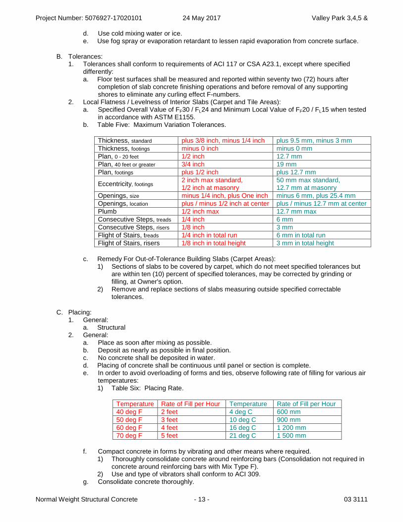
Project Number: 5076927-17020101 24 May 2017 Valley Park 3,4,5 &
Normal Weight Structural Concrete - 13 - 03 3111
d. Use cold mixing water or ice. e. Use fog spray or evaporation retardant to lessen rapid evaporation from concrete surface.
B. Tolerances: 1. Tolerances shall conform to requirements of ACI 117 or CSA A23.1, except where specified
differently: a. Floor test surfaces shall be measured and reported within seventy two (72) hours after
completion of slab concrete finishing operations and before removal of any supporting shores to eliminate any curling effect F-numbers.
2. Local Flatness / Levelness of Interior Slabs (Carpet and Tile Areas): a. Specified Overall Value of FF30 / FL24 and Minimum Local Value of FF20 / FL15 when tested
in accordance with ASTM E1155. b. Table Five: Maximum Variation Tolerances.
Thickness, standard plus 3/8 inch, minus 1/4 inch plus 9.5 mm, minus 3 mm Thickness, footings minus 0 inch minus 0 mm Plan, 0 - 20 feet 1/2 inch 12.7 mm Plan, 40 feet or greater 3/4 inch 19 mm Plan, footings plus 1/2 inch plus 12.7 mm
Eccentricity, footings2 inch max standard, 1/2 inch at masonry
50 mm max standard, 12.7 mm at masonry
Openings, size minus 1/4 inch, plus One inch minus 6 mm, plus 25.4 mm Openings, location plus / minus 1/2 inch at center plus / minus 12.7 mm at center Plumb 1/2 inch max 12.7 mm max Consecutive Steps, treads 1/4 inch 6 mm Consecutive Steps, risers 1/8 inch 3 mm Flight of Stairs, treads 1/4 inch in total run 6 mm in total run Flight of Stairs, risers 1/8 inch in total height 3 mm in total height
c. Remedy For Out-of-Tolerance Building Slabs (Carpet Areas): 1) Sections of slabs to be covered by carpet, which do not meet specified tolerances but
are within ten (10) percent of specified tolerances, may be corrected by grinding or filling, at Owner's option.
2) Remove and replace sections of slabs measuring outside specified correctable tolerances.
C. Placing: 1. General:
a. Structural 2. General:
a. Place as soon after mixing as possible. b. Deposit as nearly as possible in final position. c. No concrete shall be deposited in water. d. Placing of concrete shall be continuous until panel or section is complete. e. In order to avoid overloading of forms and ties, observe following rate of filling for various air
temperatures: 1) Table Six: Placing Rate.
Temperature Rate of Fill per Hour Temperature Rate of Fill per Hour 40 deg F 2 feet 4 deg C 600 mm 50 deg F 3 feet 10 deg C 900 mm 60 deg F 4 feet 16 deg C 1 200 mm 70 deg F 5 feet 21 deg C 1 500 mm
f. Compact concrete in forms by vibrating and other means where required. 1) Thoroughly consolidate concrete around reinforcing bars (Consolidation not required in
concrete around reinforcing bars with Mix Type F). 2) Use and type of vibrators shall conform to ACI 309.
g. Consolidate concrete thoroughly.
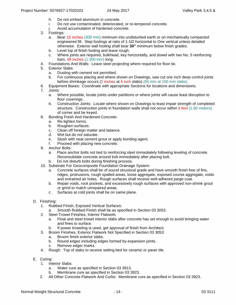
Project Number: 5076927-17020101 24 May 2017 Valley Park 3,4,5 &
Normal Weight Structural Concrete - 14 - 03 3111
h. Do not embed aluminum in concrete. i. Do not use contaminated, deteriorated, or re-tempered concrete. j. Avoid accumulation of hardened concrete.
3. Footings: a. Bear 15 inches (300 mm) minimum into undisturbed earth or on mechanically compacted
engineered fill. Step footings at ratio of 1-1/2 horizontal to One vertical unless detailed otherwise. Exterior wall footing shall bear 30” minimum below finish grades.
b. Level top of finish footing and leave rough. c. Where joints are required, bulkhead, key horizontally, and dowel with two No. 5 reinforcing
bars, 48 inches (1 200 mm) long. 4. Foundations And Walls: Leave steel projecting where required for floor tie. 5. Exterior Slabs:
a. Dusting with cement not permitted. b. For continuous placing and where shown on Drawings, saw cut one inch deep control joints
before shrinkage occurs (2 inches at 6 inch slabs) (50 mm at 150 mm slabs).6. Equipment Bases: Coordinate with appropriate Sections for locations and dimensions. 7. Joints:
a. Where possible, locate joints under partitions or where joints will cause least disruption to floor coverings.
b. Construction Joints: Locate where shown on Drawings to least impair strength of completed structure. Construction joints in foundation walls shall not occur within 6 feet (1.80 meters)of corner and be keyed.
8. Bonding Fresh And Hardened Concrete: a. Re-tighten forms. b. Roughen surfaces. c. Clean off foreign matter and laitance. d. Wet but do not saturate. e. Slush with neat cement grout or apply bonding agent. f. Proceed with placing new concrete.
9. Anchor Bolts: a. Place anchor bolts not tied to reinforcing steel immediately following leveling of concrete.
Reconsolidate concrete around bolt immediately after placing bolt. b. Do not disturb bolts during finishing process.
10. Substrate For Geocomposite Foundation Drainage System: a. Concrete surfaces shall be of sound structural grade and have smooth finish free of fins,
ridges, protrusions, rough spalled areas, loose aggregate, exposed course aggregate, voids and entrained air holes. Rough surfaces shall receive well-adhered parge coat.
b. Repair voids, rock pockets, and excessively rough surfaces with approved non-shrink grout or grind to match unrepaired areas.
c. Surfaces at cold joints shall be on same plane.
D. Finishing: 1. Rubbed Finish, Exposed Vertical Surfaces:
a. Smooth Rubbed Finish shall be as specified in Section 03 3053. 2. Steel Trowel Finishes, Interior Flatwork:
a. Float and steel trowel interior slabs after concrete has set enough to avoid bringing water and fines to surface.
b. If power troweling is used, get approval of finish from Architect. 3. Broom Finishes, Exterior Flatwork Not Specified in Section 03 3053:
a. Broom finish exterior slabs. b. Round edges including edges formed by expansion joints. c. Remove edger marks.
4. Rough: Top of slabs to receive setting bed for ceramic or paver tile.
E. Curing: 1. Interior Slabs:
a. Water cure as specified in Section 03 3913. b. Membrane cure as specified in Section 03 3923.
2. All Other Concrete Flatwork And Curbs: Membrane cure as specified in Section 03 3923.
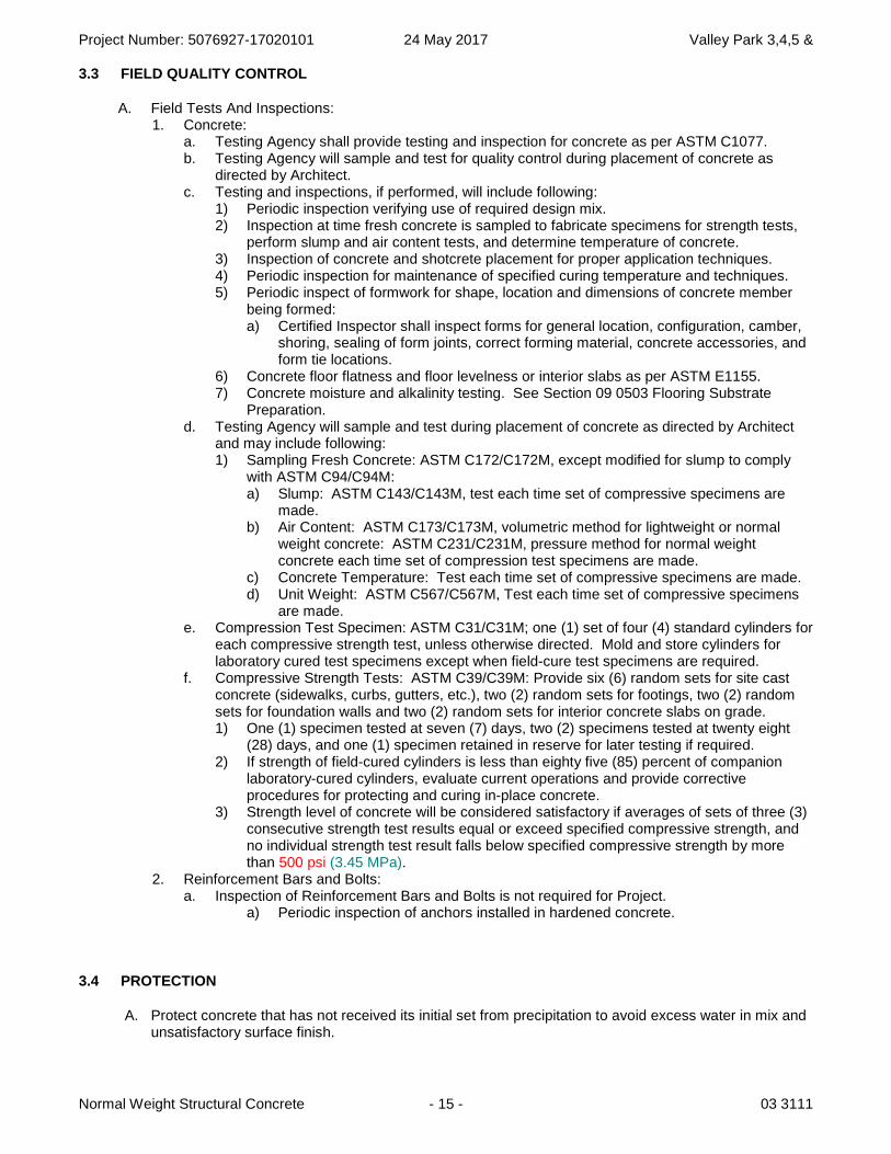
Project Number: 5076927-17020101 24 May 2017 Valley Park 3,4,5 &
Normal Weight Structural Concrete - 15 - 03 3111
3.3 FIELD QUALITY CONTROL
A. Field Tests And Inspections: 1. Concrete:
a. Testing Agency shall provide testing and inspection for concrete as per ASTM C1077. b. Testing Agency will sample and test for quality control during placement of concrete as
directed by Architect. c. Testing and inspections, if performed, will include following:
1) Periodic inspection verifying use of required design mix. 2) Inspection at time fresh concrete is sampled to fabricate specimens for strength tests,
perform slump and air content tests, and determine temperature of concrete. 3) Inspection of concrete and shotcrete placement for proper application techniques. 4) Periodic inspection for maintenance of specified curing temperature and techniques. 5) Periodic inspect of formwork for shape, location and dimensions of concrete member
being formed: a) Certified Inspector shall inspect forms for general location, configuration, camber,
shoring, sealing of form joints, correct forming material, concrete accessories, and form tie locations.
6) Concrete floor flatness and floor levelness or interior slabs as per ASTM E1155. 7) Concrete moisture and alkalinity testing. See Section 09 0503 Flooring Substrate
Preparation. d. Testing Agency will sample and test during placement of concrete as directed by Architect
and may include following: 1) Sampling Fresh Concrete: ASTM C172/C172M, except modified for slump to comply
with ASTM C94/C94M: a) Slump: ASTM C143/C143M, test each time set of compressive specimens are
made. b) Air Content: ASTM C173/C173M, volumetric method for lightweight or normal
weight concrete: ASTM C231/C231M, pressure method for normal weight concrete each time set of compression test specimens are made.
c) Concrete Temperature: Test each time set of compressive specimens are made. d) Unit Weight: ASTM C567/C567M, Test each time set of compressive specimens
are made. e. Compression Test Specimen: ASTM C31/C31M; one (1) set of four (4) standard cylinders for
each compressive strength test, unless otherwise directed. Mold and store cylinders for laboratory cured test specimens except when field-cure test specimens are required.
f. Compressive Strength Tests: ASTM C39/C39M: Provide six (6) random sets for site cast concrete (sidewalks, curbs, gutters, etc.), two (2) random sets for footings, two (2) random sets for foundation walls and two (2) random sets for interior concrete slabs on grade. 1) One (1) specimen tested at seven (7) days, two (2) specimens tested at twenty eight
(28) days, and one (1) specimen retained in reserve for later testing if required. 2) If strength of field-cured cylinders is less than eighty five (85) percent of companion
laboratory-cured cylinders, evaluate current operations and provide corrective procedures for protecting and curing in-place concrete.
3) Strength level of concrete will be considered satisfactory if averages of sets of three (3) consecutive strength test results equal or exceed specified compressive strength, and no individual strength test result falls below specified compressive strength by more than 500 psi (3.45 MPa).
2. Reinforcement Bars and Bolts: a. Inspection of Reinforcement Bars and Bolts is not required for Project.
a) Periodic inspection of anchors installed in hardened concrete.
3.4 PROTECTION
A. Protect concrete that has not received its initial set from precipitation to avoid excess water in mix and unsatisfactory surface finish.
Project Number: 5076927-17020101 24 May 2017 Valley Park 3,4,5 &
Normal Weight Structural Concrete - 16 - 03 3111
B. Do not allow materials resulting from construction activities, which will affect concrete or application of finish floor systems adversely, to come in contact with interior concrete slabs.
C. Protect interior concrete floors from stains, paint, mortar and other construction activities.
END OF SECTION
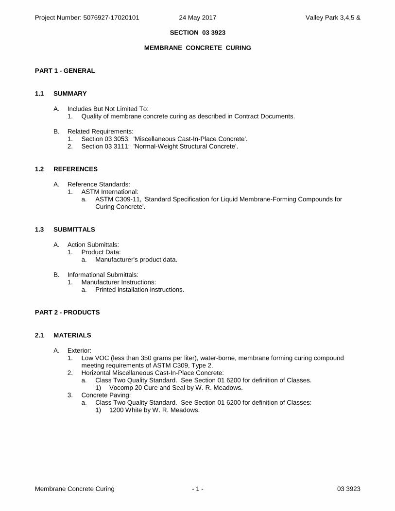
Project Number: 5076927-17020101 24 May 2017 Valley Park 3,4,5 &
Membrane Concrete Curing - 1 - 03 3923
SECTION 03 3923
MEMBRANE CONCRETE CURING
PART 1 - GENERAL
1.1 SUMMARY
A. Includes But Not Limited To: 1. Quality of membrane concrete curing as described in Contract Documents.
B. Related Requirements: 1. Section 03 3053: 'Miscellaneous Cast-In-Place Concrete'. 2. Section 03 3111: 'Normal-Weight Structural Concrete'.
1.2 REFERENCES
A. Reference Standards: 1. ASTM International:
a. ASTM C309-11, 'Standard Specification for Liquid Membrane-Forming Compounds for Curing Concrete'.
1.3 SUBMITTALS
A. Action Submittals: 1. Product Data:
a. Manufacturer's product data.
B. Informational Submittals: 1. Manufacturer Instructions:
a. Printed installation instructions.
PART 2 - PRODUCTS
2.1 MATERIALS
A. Exterior: 1. Low VOC (less than 350 grams per liter), water-borne, membrane forming curing compound
meeting requirements of ASTM C309, Type 2. 2. Horizontal Miscellaneous Cast-In-Place Concrete:
a. Class Two Quality Standard. See Section 01 6200 for definition of Classes. 1) Vocomp 20 Cure and Seal by W. R. Meadows.
3. Concrete Paving: a. Class Two Quality Standard. See Section 01 6200 for definition of Classes:
1) 1200 White by W. R. Meadows.
Project Number: 5076927-17020101 24 May 2017 Valley Park 3,4,5 &
Membrane Concrete Curing - 2 - 03 3923
PART 3 - EXECUTION
3.1 PREPARATION
A. Protection of In-Place Conditions: 1. Protect surfaces that will be receiving products or systems incompatible with curing compounds. 2. Where such surfaces do receive curing compound, remove to extent required by installer of
products and systems to be subsequently installed and at no additional cost to Owner.
3.2 APPLICATION
A. Interface With Other Work: 1. Apply concrete sealer finishing approximately 1/2 hour before application of Membrane Concrete
Curing.
END OF SECTION
Project Number: 5076927-17020101 24 May 2017 Valley Park 3,4,5 &
Non-Metallic Non-Shrink Grouting - 1 - 03 6213
SECTION 03 6213
NON-METALLIC NON-SHRINK GROUTING
PART 1 - GENERAL
1.1 SUMMARY
A. Includes But Not Limited To: 1. Furnish and install structural grout as described in Contract Documents.
a. For securing anchor bolts and hardware in concrete. b. For securing anchor bolts and hardware in masonry.
B. Related Requirements: 1. Section 04 0516: Masonry grout.
1.2 REFERENCES
A. Association Publications: 1. American Concrete Institute:
a. ACI 305R-10, ‘Guide to Hot Weather Concreting’. b. ACI 306R-10, 'Guide to Cold Weather Concreting’. c. ACI 351.1R-12, ‘Grouting Between Foundations and Bases for Support of Equipment and
Machinery’.
B. Reference Standards: 1. ASTM International:
a. ASTM C33/C33M-11a, ‘Standard Specification for Concrete Aggregates’. b. ASTM C78/C78M-10, ‘Standard Test Method for Flexural Strength of Concrete (Using
Simple Beam with Third-Point Loading)’. c. ASTM C109/C109M-11b, ‘Standard Test Method for Compressive Strength of Hydraulic
Cement Mortars (Using 2-in. or [50-mm] Cube Specimens)’. d. ASTM C191-08, ‘Standard Test Methods for Time of Setting of Hydraulic Cement by Vicat
Needle’. e. ASTM C230/C230M-08, ‘Standard Specification for Flow Table for Use in Tests of Hydraulic
Cement’. f. ASTM C266-08e1, ‘Standard Test Method for Time of Setting of Hydraulic-Cement Paste by
Gillmore Needles’. g. ASTM C293/C293M-10, ‘Standard Test Method for Flexural Strength of Concrete (Using
Simple Beam With Center-Point Loading)’. h. ASTM C307-03(2008), ‘Standard Test Method for Tensile Strength of Chemical-Resistant
Mortar, Grouts, and Monolithic Surfacings’. i. ASTM C309-11, ‘Standard Specification for Liquid Membrane-Forming Compounds for
Curing Concrete’. j. ASTM C348-08, ‘Standard Test Method for Flexural Strength of Hydraulic-Cement Mortars’. k. ASTM C469/C469M-10, ‘Standard Test Method for Static Modulus of Elasticity and
Poisson's Ratio of Concrete in Compression’. l. ASTM C496/C496M-04e1, ‘Standard Test Method for Splitting Tensile Strength of Cylindrical
Concrete Specimens’. m. ASTM C531-00(2005), ‘Standard Test Method for Linear Shrinkage and Coefficient of
Thermal Expansion of Chemical-Resistant Mortars, Grouts, Monolithic Surfacings, and Polymer Concretes’.
n. ASTM C579-01(2006), ‘Standard Test Methods for Compressive Strength of Chemical-Resistant Mortars, Grouts, Monolithic Surfacings, and Polymer Concretes’
Project Number: 5076927-17020101 24 May 2017 Valley Park 3,4,5 &
Non-Metallic Non-Shrink Grouting - 2 - 03 6213
o. ASTM C580-02(2008), ‘Standard Test Method for Flexural Strength and Modulus of Elasticity of Chemical-Resistant Mortars, Grouts, Monolithic Surfacings, and Polymer Concretes’.
p. ASTM C666/C666M-03(2008), ‘Standard Test Method for Resistance of Concrete to Rapid Freezing and Thawing’.
q. ASTM C827/C827M-10, ‘Standard Test Method for Change in Height at Early Ages of Cylindrical Specimens of Cementitious Mixtures’.
r. ASTM C882/C882M-12, ‘Standard Test Method for Bond Strength of Epoxy-Resin Systems Used With Concrete By Slant Shear’.
s. ASTM C939-10, ‘Standard Test Method for Flow of Grout for Preplaced-Aggregate Concrete (Flow Cone Method)’.
t. ASTM C940-10a, ‘Standard Test Method for Expansion and Bleeding of Freshly Mixed Grouts for Preplaced-Aggregate Concrete in the Laboratory’.
u. ASTM C942-10, ‘Standard Test Method for Compressive Strength of Grouts for Preplaced-Aggregate Concrete in the Laboratory’.
v. ASTM C1090-10, ‘Standard Test Method for Measuring Changes in Height of Cylindrical Specimens of Hydraulic-Cement Grout’.
w. ASTM C1107/C1107M-11, 'Standard Specification for Packaged Dry, Hydraulic-Cement Grout (Non-shrink).'
x. ASTM C1202-12, ‘Standard Test Method for Electrical Indication of Concrete's Ability to Resist Chloride Ion Penetration’.
y. ASTM E488-10, ‘Standard Test Methods for Strength of Anchors in Concrete Elements’.
2. United States Army Corps of Engineers (USACE): a. CRD C-621-93, ‘Handbook for Concrete and Cement Standard Specification for Packaged,
Dry, Hydraulic-Cement Grout (Nonshrink’.
1.3 SUBMITTALS
A. Action Submittals 1. Product Data:
a. Manufacturer's data sheets on each product to be used, including: 1) Preparation instructions and recommendations. 2) Storage and handling requirements and recommendations. 3) Manufacturer's printed installation instructions for each product.
1.4 DELIVERY, STORAGE AND HANDLING
A. Delivery And Acceptance Requirements: 1. Materials shall be delivered in original, unopened packages with labels intact clearly identifying
product name and manufacturer until time of use.
B. Storage And Handling Requirements: 1. Follow Manufacturer’s recommendations including but not limited to following:
a. Store in clean, dry location. b. Keep containers sealed until ready for use. c. Store materials at room temperature before use.
2. Protect materials during handling and placement to prevent damage or contamination. a. Protect materials from freezing or overheating.
3. Shelf Life: One (1) year minimum in original, unopened containers.
1.5 FIELD CONDITIONS
A. Ambient Conditions: 1. General:
a. Do not place grout over frozen concrete.
Project Number: 5076927-17020101 24 May 2017 Valley Park 3,4,5 &
Non-Metallic Non-Shrink Grouting - 3 - 03 6213
2. Maintain environmental conditions and protect Work during and after installation to comply with referenced standards and Manufacturer’s printed recommendations: a. Do not install products under environmental conditions outside Manufacturer’s
recommendations. 3. Follow ACI requirements for cold and hot weather concreting or Manufacturer’s written
instructions, whichever is more stringent: a. Cold Weather Limitations:
1) Follow requirements of ACI 306R for cold weather concreting. b. Hot Weather Limitations:
1) Follow requirements of ACI 305R for hot weather concreting. c. ACI 305R-10, ‘Guide to Hot Weather Concreting’. d. ACI 306R-10, 'Guide to Cold Weather Concreting’.
PART 2 - PRODUCTS
2.1 MATERIALS
A. Design Criteria: 1. Description:
a. Commercial non-shrink, non-metallic grout. 2. Meet following requirements:
a. ASTM C1107/C1107M, Type B or Type C. b. Corps and Engineers CRD C-621. c. Compressive strength of 6000 psi (41 MPa) minimum.
B. Type Two Acceptable Products: 1. Masterflow 928 by BASF Systems, Shakopee, MN or BASF Canada, Mississauga, ON
www.buildingsystems.basf.com.2. ProSpec F77 by Bonsal American, Inc., Charlotte, NC www.bonsal.com. 3. Advantage 1107 Grout by Dayton Superior Corporation, Oregon, IL
www.daytonsuperiorchemical.com. 4. NS Grout by Euclid Chemical Company, Cleveland, OH www.euclidchemical.com. 5. Five Star Grout by Five Star Products Inc, Fairfield, CT www.fivestarproducts.com. 6. Duragrout by L&M Construction Chemicals Inc., Omaha, NE www.lmcc.com. 7. Planigrout 712 by MAPEI Corporation, Deerfield Beach, FL www.mapei.US or Mapei Inc., Laval,
QC www.mapei.com/CA. 8. SikaGrout 212 by Sika Corporation, Lyndhurst, NJ www.usa.sika.com or Sika Canada, Inc.
Pointe-Claire, QC www.can.sika.com. 9. MP Grout by US Mix Products Company, Denver, CO www.usspec.com. 10. Sealtight CG-86 Grout by W R Meadows, Hampshire, IL www.meadows.com. 11. Equal as approved by Architect before installation. See Section 01 6200.
PART 3 - EXECUTION
3.1 EXAMINATION
A. Verification Of Conditions: 1. Examine substrate and verify substrate is suitable for installation. 2. Notify Architect of unsuitable conditions in writing.
a. Do not install board over unsuitable conditions. b. Commencement of Work by installer is considered acceptance of substrate.
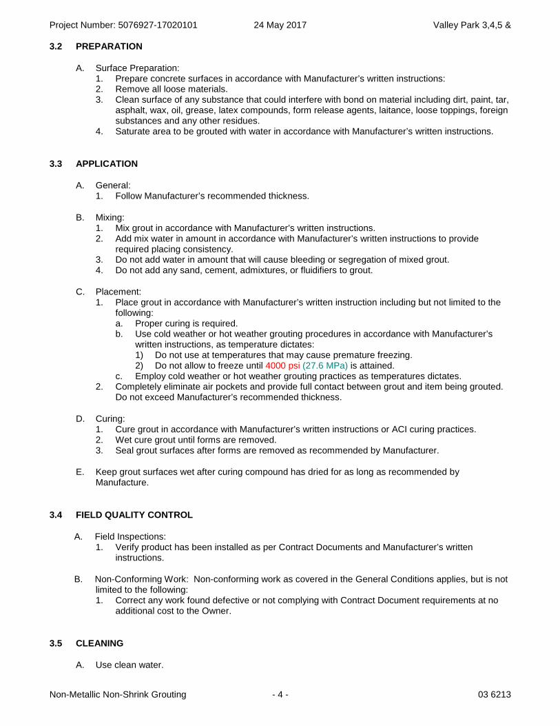
Project Number: 5076927-17020101 24 May 2017 Valley Park 3,4,5 &
Non-Metallic Non-Shrink Grouting - 4 - 03 6213
3.2 PREPARATION
A. Surface Preparation: 1. Prepare concrete surfaces in accordance with Manufacturer’s written instructions: 2. Remove all loose materials. 3. Clean surface of any substance that could interfere with bond on material including dirt, paint, tar,
asphalt, wax, oil, grease, latex compounds, form release agents, laitance, loose toppings, foreign substances and any other residues.
4. Saturate area to be grouted with water in accordance with Manufacturer’s written instructions.
3.3 APPLICATION
A. General: 1. Follow Manufacturer’s recommended thickness.
B. Mixing: 1. Mix grout in accordance with Manufacturer’s written instructions. 2. Add mix water in amount in accordance with Manufacturer’s written instructions to provide
required placing consistency. 3. Do not add water in amount that will cause bleeding or segregation of mixed grout. 4. Do not add any sand, cement, admixtures, or fluidifiers to grout.
C. Placement: 1. Place grout in accordance with Manufacturer’s written instruction including but not limited to the
following: a. Proper curing is required. b. Use cold weather or hot weather grouting procedures in accordance with Manufacturer’s
written instructions, as temperature dictates: 1) Do not use at temperatures that may cause premature freezing. 2) Do not allow to freeze until 4000 psi (27.6 MPa) is attained.
c. Employ cold weather or hot weather grouting practices as temperatures dictates. 2. Completely eliminate air pockets and provide full contact between grout and item being grouted.
Do not exceed Manufacturer’s recommended thickness.
D. Curing: 1. Cure grout in accordance with Manufacturer’s written instructions or ACI curing practices. 2. Wet cure grout until forms are removed. 3. Seal grout surfaces after forms are removed as recommended by Manufacturer.
E. Keep grout surfaces wet after curing compound has dried for as long as recommended by Manufacture.
3.4 FIELD QUALITY CONTROL
A. Field Inspections: 1. Verify product has been installed as per Contract Documents and Manufacturer’s written
instructions.
B. Non-Conforming Work: Non-conforming work as covered in the General Conditions applies, but is not limited to the following: 1. Correct any work found defective or not complying with Contract Document requirements at no
additional cost to the Owner.
3.5 CLEANING
A. Use clean water.

Project Number: 5076927-17020101 24 May 2017 Valley Park 3,4,5 &
Non-Metallic Non-Shrink Grouting - 5 - 03 6213
B. Clean tools and equipment with water before material hardens.
3.6 PROTECTION
A. Follow Manufacturer’s recommendation for protection when applying material.
B. Protect placed grout from freezing until minimum strength of 4000 psi (27.58 MPa) is reached.
C. Protect placed grout from damage during construction.
END OF SECTION
Project Number: 5076927-17020101 24 May 2017 Valley Park 3,4,5 &
Non-Metallic Non-Shrink Grouting - 6 - 03 6213
B L A N K P A G E
Project Number: 5076927-17020101 24 May 2017 Valley Park 3,4,5 &
Epoxy Grouting - 1 - Section 03 6300
SECTION 03 6300
EPOXY GROUTING
PART 1 - GENERAL
1.1 SUMMARY
A. Includes But Not Limited to: 1. Furnish and install epoxy grouting as described in Contract Documents.
1.2 REFERENCES
A. Reference Standards: 1. American Society For Testing And Materials:
a. ASTM D 638-00, 'Standard Test Method for Tensile Properties of Plastics.'
PART 2 - PRODUCTS
2.1 MATERIALS
A. Epoxy Grout: 1. Type One Acceptable Productsto be used in Concrete Applications:
a. “HIT RE 500” by Hilti Corporation b. “SET-XP” by Simpson Strong Tie c. Equal as approved by Architect before bidding. See Section 01 6200.
2. Acceptable Products to be used in Masonry Applications: a. “HIT HY 150 MAX” or “HIT HY 70” by Hilti Corporation (In grouted cells) b. “HIT HY 70” by Hilti Corporation (In un-reinforced masonry cells w/screen tubes) c. “SET-EPOXY-TIE” by Simpson Strong Tie d. “Power-Fast” by Powers Fasteners e. Equal as approved by Architect before bidding. See Section 01 6200.
PART 3 - EXECUTION
3.1 PREPARATION
A. All drilled holes for anchor rods 1” in diameter and smaller shall be 1/8” larger than the anchor rod being installed. All drilled holes for anchor rods greater than 1” in diameter shall be ¼” larger than the bar or anchor rod being installed.
B. After drilling the proper size hole, clean the walls and bottom of the drilled hole of all dust and debris using a nylon brush in conjunction with oil free compressed air. The hole shall be free of dust, dirt, debris and standing water.
C. Follow all manufacturers’ recommendations for epoxy installation.
END OF SECTION
Project Number: 5076927-17020101 24 May 2017 Valley Park 3,4,5 &
Epoxy Grouting - 2 - Section 03 6300
BLANK PAGE