d gb usa f nl 22671
TRANSCRIPT

Modell der Diesellokomotive NOHAB, Di3
22671F D GB USA NL

2

3
Inhaltsverzeichnis: SeiteInformationen zum Vorbild 4Sicherheitshinweise 6Wichtige Hinweise 6Multiprotokollbetrieb 6Hinweise zum Digitalbetrieb 7Schaltbare Funktionen 9Parameter/Register 10Wartung und Instandhaltung 26Ersatzteile 30
Table of Contents: Page Information about the prototype 4Safety Notes 11Important Notes 11Multi-Protocol Operation 11Notes on digital operation 12Controllable Functions 14Parameter/Register 15Service and maintenance 26Spare Parts 30
Sommaire : PageInformations concernant la locomotive réelle 5Remarques importantes sur la sécurité 16Information importante 16Mode multiprotocole 16Remarques relatives au fonctionnement en mode digital 17Fonctions commutables 19Paramètre/Registre 20Entretien et maintien 26Pièces de rechange 30
Inhoudsopgave: PaginaInformatie van het voorbeeld 5Veiligheidsvoorschriften 21Belangrijke aanwijzing 21Multiprotocolbedrijf 21Aanwijzingen voor digitale besturing 22Schakelbare functies 24Parameter/Register 25Onderhoud en handhaving 26Onderdelen 30

4
Informationen zum Vorbild Basis der auch als „Rundnasen, „Kartoffelkäfer“ oder „Bulldogs“ bezeichneten NOHAB-Maschinen waren die berühmten US-amerikanischen F7/FP7-Dieselloks der Electro-Motive Division (EMD von General Motors, GM). Doch das direkte Vorbild der NOHAB´s stammt nicht aus Amerika sondern aus Australien, da hier ein eher europäisches Lichtraumprofil vorherrschte und vom australischen Lizenznehmer auch eine sechsachsige Zweirichtungsvariante produziert wurde. Daraus entstand dann Anfang der 1950er-Jahre bei GM/EMD die europäische Lizenzvariante AA16. Ihr Kastenaufbau ruhte auf zwei dreiachsigen Flexicoil-Drehgestellen mit Antrieb auf allen Radsätzen oder nur auf jeweils den beiden Endradsätzen. Die Leistungsübertragung erfolgte durch den bewährten GM-Antriebsstrang mit Gleichstromkraftübertragung, wobei der an den Dieselmotor angeflanschte Hauptgenerator die Tatzlagerfahrmotoren der Antriebsradsätze speiste. Der langsam laufende, wasser-gekühlte Zweitakt-Dieselmotor des Typs GM 567 war in acht Fahrstufen regelbar. Letztendlich entsprach die eher archaische Dieselelektrik – basierend auf den GM-Großseri-enmodellen der 1930er- und 1940er-Jahre – nicht mehr dem neuesten Stand der Technik, hatte sich aber zwischenzeit-lich bei Tausenden von Loks bewährt.
Information about the prototypeThe famous American F7/FP7 diesel locomotives of the Electro-Motive Division (EMD of General Motors, GM) were the basis for the NOHAB units also known as the „Round Noses“, „Potato Beetles“, or „Bulldogs“. However, the direct prototype of the NOHABs did not come from America rather from Australia, since a rather European clearance gauge prevailed here and a six-axle bi-directional variant was also built by an Australian licensee. At the start of the Fifties, the European licensing variant AA16 was developed from this unit at GM/EMD. Its box body rode on two three-axle Flexicoil trucks with all of the wheel sets powered in both trucks or just the outer wheel sets of the trucks. The power transmission was done with the proven GM drive train with DC power transmission, whereby the main generator flange-mounted to the diesel motor powered the axle-suspended traction motors for the powered wheel sets. The type GM 567 two-stroke diesel motor was a slow-turning unit that was water-cooled and that could be controlled in eight speed steps. Finally, this rather archaic diesel electric – based on the GM regular production models of the Thirties and Forties – was no longer the latest level of technology, but it had proven itself over the years in thousands of locomotives.
5
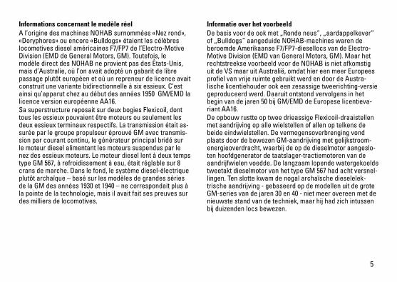
Informations concernant le modèle réel A l’origine des machines NOHAB surnommées «Nez rond», «Doryphores» ou encore «Bulldogs» étaient les célèbres locomotives diesel américaines F7/FP7 de l’Electro-Motive Division (EMD de General Motors, GM). Toutefois, le modèle direct des NOHAB ne provient pas des États-Unis, mais d’Australie, où l’on avait adopté un gabarit de libre passage plutôt européen et où un repreneur de licence avait construit une variante bidirectionnelle à six essieux. C’est ainsi qu’apparut chez au début des années 1950 GM/EMD la licence version européenne AA16. Sa superstructure reposait sur deux bogies Flexicoil, dont tous les essieux pouvaient être moteurs ou seulement les deux essieux terminaux respectifs. La transmission était as-surée par le groupe propulseur éprouvé GM avec transmis-sion par courant continu, le générateur principal bridé sur le moteur diesel alimentant les moteurs suspendus par le nez des essieux moteurs. Le moteur diesel lent à deux temps type GM 567, à refroidissement à eau, était réglable sur 8 crans de marche. Dans le fond, le système diesel-électrique plutôt archaïque – basé sur les modèles de grandes séries de la GM des années 1930 et 1940 – ne correspondait plus à la pointe de la technologie, mais il avait fait ses preuves sur des milliers de locomotives.
Informatie over het voorbeeldDe basis voor de ook met „Ronde neus“, „aardappelkever“ of „Bulldogs“ aangeduide NOHAB-machines waren de beroemde Amerikaanse F7/FP7-diesellocs van de Electro-Motive Division (EMD van General Motors, GM). Maar het rechtstreekse voorbeeld voor de NOHAB is niet afkomstig uit de VS maar uit Australië, omdat hier een meer Europees profiel van vrije ruimte gebruikt werd en door de Austra-lische licentiehouder ook een zesassige tweerichting-versie geproduceerd werd. Daaruit ontstond vervolgens in het begin van de jaren 50 bij GM/EMD de Europese licentieva-riant AA16. De opbouw rustte op twee drieassige Flexicoil-draaistellen met aandrijving op alle wielstellen of allen op telkens de beide eindwielstellen. De vermogensoverbrenging vond plaats door de bewezen GM-aandrijving met gelijkstroom-energieoverdracht, waarbij de op de dieselmotor aangeslo-ten hoofdgenerator de taatslager-tractiemotoren van de aandrijfwielen voedde. De langzaam lopende watergekoelde tweetakt dieselmotor van het type GM 567 had acht versnel-lingen. Ten slotte kwam de nogal archaïsche dieselelek-trische aandrijving - gebaseerd op de modellen uit de grote GM-series van de jaren 30 en 40 - niet meer overeen met de nieuwste stand van de techniek, maar hij had zich intussen bij duizenden locs bewezen.
6
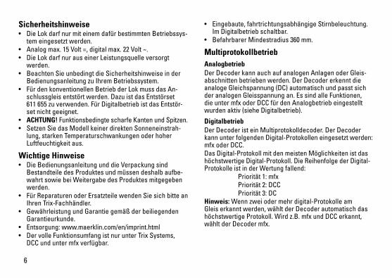
Sicherheitshinweise • DieLokdarfnurmiteinemdafürbestimmtenBetriebssys-
tem eingesetzt werden.• Analogmax.15Volt=,digitalmax.22Volt~.• DieLokdarfnurauseinerLeistungsquelleversorgt
werden.• BeachtenSieunbedingtdieSicherheitshinweiseinder
Bedienungsanleitung zu Ihrem Betriebssystem.• FürdenkonventionellenBetriebderLokmussdasAn-
schlussgleis entstört werden. Dazu ist das Entstörset 611 655 zu verwenden. Für Digitalbetrieb ist das Entstör-set nicht geeignet.
• ACHTUNG! Funktionsbedingte scharfe Kanten und Spitzen.• SetzenSiedasModellkeinerdirektenSonneneinstrah-
lung, starken Temperaturschwankungen oder hoher Luftfeuchtigkeit aus.
Wichtige Hinweise • DieBedienungsanleitungunddieVerpackungsind
Bestandteile des Produktes und müssen deshalb aufbe-wahrt sowie bei Weitergabe des Produktes mitgegeben werden.
• FürReparaturenoderErsatzteilewendenSiesichbitteanIhren Trix-Fachhändler.
• GewährleistungundGarantiegemäßderbeiliegendenGarantieurkunde.
• Entsorgung:www.maerklin.com/en/imprint.html• DervolleFunktionsumfangistnurunterTrixSystems,
DCC und unter mfx verfügbar.
• Eingebaute,fahrtrichtungsabhängigeStirnbeleuchtung. Im Digitalbetrieb schaltbar.
• BefahrbarerMindestradius360mm.
Multiprotokollbetrieb AnalogbetriebDer Decoder kann auch auf analogen Anlagen oder Gleis-abschnitten betrieben werden. Der Decoder erkennt die analoge Gleichspannung (DC) automatisch und passt sich der analogen Gleisspannung an. Es sind alle Funktionen, die unter mfx oder DCC für den Analogbetrieb eingestellt wurden aktiv (siehe Digitalbetrieb).
DigitalbetriebDer Decoder ist ein Multiprotokolldecoder. Der Decoder kannunterfolgendenDigital-Protokolleneingesetztwerden:mfx oder DCC. Das Digital-Protokoll mit den meisten Möglichkeiten ist das höchstwertige Digital-Protokoll. Die Reihenfolge der Digital-ProtokolleistinderWertungfallend: Priorität1:mfx Priorität2:DCC Priorität3:DCHinweis: Wenn zwei oder mehr digital-Protokolle am Gleis erkannt werden, wählt der Decoder automatisch das höchstwertige Protokoll. Wird z.B. mfx und DCC erkannt, wählt der Decoder mfx.

7
Hinweis: Beachten Sie, dass nicht alle Funktionen in allen Digital-Protokollen möglich sind. Unter mfx und DCC können einige Einstellungen von Funktionen, welche im Analog-Betrieb wirksam sein sollen, vorgenommen werden.
Hinweise zum Digitalbetrieb • DiegenaueVorgehensweisezumEinstellenderdiversen
Parameter entnehmen Sie bitte der Bedienungsanleitung Ihrer Mehrzug-Zentrale.
• DieabWerkeingestelltenWertesindfürmfxgewählt,sodass ein bestmöglichstes Fahrverhalten gewährleistet ist. Für andere Betriebssysteme müssen gegebenenfalls Anpassungen getätigt werden.
• DerBetriebmitgegenpoligerGleichspannungimBremsabschnitt ist mit der werkseitigen Einstellung nicht möglich. Ist diese Eigenschaft gewünscht, so muss auf den konventionellen Gleichstrombetrieb verzichtet werden(CV29/Bit2=0).
mfx-Protokoll
Adressierung • KeineAdresseerforderlich,jederDecodererhälteine
einmalige und eindeutige Kennung (UID).• DerDecodermeldetsichaneinerCentralStationoder
Mobile Station mit seiner UID automatisch an.• NameabWerk:Di3 624 NSB
Programmierung• DieEigenschaftenkönnenüberdiegrafischeOberfläche
der Central Station bzw. teilweise auch mit der Mobile Station programmiert werden.
• EskönnenalleConfigurationVariablen(CV)mehrfachgelesen und programmiert werden.
• DieProgrammierungkannentwederaufdemHaupt-oderdem Programmiergleis erfolgen.
• DieDefaulteinstellungen(Werkseinstellungen)könnenwieder hergestellt werden.
• Funktionsmapping:FunktionenkönnenmitHilfederCentral Station 60212 (eingeschränkt) und mit der Central Station 60213/60214/60215 beliebigen Funktionstasten zugeordnet werden (siehe Hilfe in der Central Station).

8
DCC-Protokoll
Adressierung• MöglicheAdressen:Kurze,langeundTraktionsadresse• Adressbereich:
1 – 127 (kurze Adresse, Traktionsadresse) 1 – 10239 (lange Adresse)• JedeAdresseistmanuellprogrammierbar.• KurzeoderlangeAdressewirdüberdieCVsausgewählt.• EineangewandteTraktionsadressedeaktiviertdie
Standard-Adresse.
Programmierung• DieEigenschaftenkönnenüberdieConfigurationsVari-
ablen (CV) mehrfach geändert werden. • DieCV-NummerunddieCV-Wertewerdendirekteinge-
geben.• DieCVskönnenmehrfachgelesenundprogrammiert
werden (Programmierung auf dem Programmiergleis).• DieCVskönnenbeliebigprogrammiertwerden.PoM
(Programmierung auf dem Hauptgleis PoM) ist nur bei den in der CV-Tabelle gekennzeichneten CV möglich. PoM muss von Ihrer Zentrale unterstützt werden (siehe Bedienungsanleitung ihres Gerätes).
• DieDefaulteinstellungen(Werkseinstellungen)könnenwieder hergestellt werden.
• 14bzw.28/126Fahrstufeneinstellbar.• AlleFunktionenkönnenentsprechenddemFunktions-
mapping geschaltet werden.• WeitereInformation,sieheCV-TabelleDCC-Protokoll.
Es wird empfohlen, die Programmierungen grundsätzlich auf dem Programmiergleis vorzunehmen.
Logische Funktionen
Anfahr-/Bremsverzögerung• DieBeschleunigungs-undBremszeitkönnengetrennt
von einander eingestellt werden. • DielogischeFunktionsabschaltungABVkannüberdas
Funktionsmapping auf jede beliebige Funktionstaste gelegt werden.

9
Schaltbare Funktionen
Spitzensignal an Funktion f0 Funktion f0
Geräusch:Betriebsgeräusch — Funktion 2 Funktion f2 Funktion f2
Geräusch:Signalhorn — Funktion 3 Funktion f3 Funktion f3
ABV aus — Funktion 4 Funktion f4 Funktion f4
Geräusch:Bremsenquietschen — Funktion 5 Funktion f5 Funktion f5
Spitzensignal Führerstand 2 aus * — Funktion 6 Funktion f6 Funktion f6
Geräusch:Schaffnerpfiff — Funktion 7 Funktion f7 Funktion f7
Spitzensignal Führerstand 1 aus * — Funktion 8 Funktion f8 Funktion f8
Geräusch:Rangierpfiff — — Funktion f9 Funktion f9
Rangiergang — — Funktion f10 Funktion f10
Führerstandsbeleuchtung Führerstand 1 — — Funktion f11 Funktion f11
Führerstandsbeleuchtung Führerstand 2 — — Funktion f12 Funktion f12
Rangierlicht doppel A — — f0 + f6 + f8 f0 + f6 + f8
STOP mobile station
1 5 f0 f8 f0f8f0 - f3 f4 - f7
* nur in Verbindung mit Spitzensignal
10
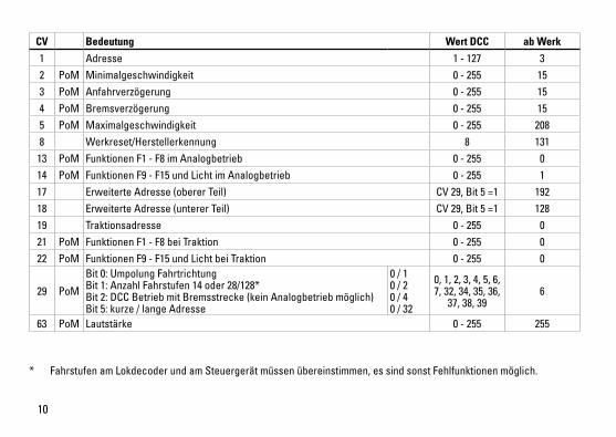
CV Bedeutung Wert DCC ab Werk
1 Adresse 1 - 127 3 2 PoM Minimalgeschwindigkeit 0 - 255 153 PoM Anfahrverzögerung 0 - 255 154 PoM Bremsverzögerung 0 - 255 155 PoM Maximalgeschwindigkeit 0 - 255 2088 Werkreset/Herstellerkennung 8 131
13 PoM Funktionen F1 - F8 im Analogbetrieb 0 - 255 014 PoM Funktionen F9 - F15 und Licht im Analogbetrieb 0 - 255 117 Erweiterte Adresse (oberer Teil) CV29,Bit5=1 19218 Erweiterte Adresse (unterer Teil) CV29,Bit5=1 12819 Traktionsadresse 0 - 255 021 PoM Funktionen F1 - F8 bei Traktion 0 - 255 022 PoM Funktionen F9 - F15 und Licht bei Traktion 0 - 255 0
29 PoM
Bit0:UmpolungFahrtrichtung Bit1:AnzahlFahrstufen14oder28/128* Bit2:DCCBetriebmitBremsstrecke(keinAnalogbetriebmöglich) Bit5:kurze/langeAdresse
0 / 1 0 / 2 0 / 4 0 / 32
0, 1, 2, 3, 4, 5, 6, 7, 32, 34, 35, 36,
37, 38, 396
63 PoM Lautstärke 0 - 255 255
* Fahrstufen am Lokdecoder und am Steuergerät müssen übereinstimmen, es sind sonst Fehlfunktionen möglich.

11
travel. They can be turned on and off in digital operation. • Minimumradiusforoperationis360mm/14-3/16“.
Multi-Protocol Operation Analog OperationThis decoder can also be operated on analog layouts or ar-eas of track that are analog. The decoder recognizes alter-nating current (DC) and automatically adapts to the analog track voltage. All functions that were set under mfx or DCC for analog operation are active (see Digital Operation).
Digital OperationThe decoders are multi-protocol decoders. These decoders canbeusedunderthefollowingdigitalprotocols:mfxorDCC.The digital protocol with the most possibilities is the highest order digital protocol. The sequence of digital protocols in descendingorderis: Priority1:mfx Priority2:DCC Priority3:DCNote: If two or more digital protocols are recognized in the track, the decoder automatically takes on the highest value digital protocol.For example, if mfx & DCC are recognized, the mfx digital protocol is taken on by the decoder.Note: Please note that not all functions are possible in all digital protocols. Several settings for functions, which are supposed to be active in analog operation, can be done under mfx and DCC.
Safety Notes• Thislocomotiveisonlytobeusedwiththeoperating
system it is designed for.• Analogmax.15voltsDC,digitalmax.22voltsAC.• Thislocomotivemustneverbesuppliedwithpowerfrom
more than one power pack.• Pleasemakenoteofthesafetynotesintheinstructions
for your operating system.• Thefeedertrackmustbeequippedtopreventinter-
ference with radio and television reception, when the locomotive is to be run in conventional operation. The 611 655 interference suppression set is to be used for this purpose. The interference suppression set is not suitable for digital operation.
• WARNING! Sharp edges and points required for operation.• Donotexposethemodeltodirectsunlight,extreme
changes in temperature, or high humidity.
Important Notes• Theoperatinginstructionsandthepackagingareacom-
ponent part of the product and must therefore be kept as well as transferred along with the product to others.
• PleaseseeyourauthorizedTrixdealerforrepairsorspare parts.
• Thewarrantycardincludedwiththisproductspecifiesthe warranty conditions.
• Disposing:www.maerklin.com/en/imprint.html• ThefullrangeoffunctionsisonlyavailableunderTrix
Systems and under DCC and mfx.• Built-inheadlightsthatchangeoverwiththedirectionof

12
Notes on digital operation • Theoperatinginstructionsforyourcentralunitwillgive
you exact procedures for setting the different parame-ters.
• Thevaluessetatthefactoryhavebeenselectedformfxin order to guarantee the best possible running characte-ristics. Adjustments may have to be made for other operating systems.
• Thesettingdoneatthefactorydoesnotpermitoperationwith opposite polarity DC power in the braking block. If you want this characteristic, you must do without conventionalDCpoweroperation(CV29/Bit2=0).
mfx Protocol
Addresses • Noaddressisrequired;eachdecoderisgivenaone-
time, unique identifier (UID).• ThedecoderautomaticallyregistersitselfonaCentral
Station or a Mobile Station with its UID.• Namesetatthefactory:Di3 624 NSB
Programming • Thecharacteristicscanbeprogrammedusingthe
graphic screen on the Central Station or also partially with the Mobile Station.
• AlloftheConfigurationVariables(CV)canbereadandprogrammed repeatedly.
• Theprogrammingcanbedoneeitheronthemaintrackorthe programming track.
• Thedefaultsettings(factorysettings)canbeproducedrepeatedly.
• Functionmapping:Functionscanbeassignedtoanyofthe function buttons with the help of the 60212 Central Station (with limitations) and with the 60213/60214/60215 Central Station (See help section in the Central Station).

13
DCC Protocol
Addresses • Possibleaddresses:short,long,andm.u.address• Addressrange:
1 – 127 (short address, m.u. address) 1 – 10239 (long address)
• Everyaddresscanbeprogrammedmanually.• AshortoralongaddressisselectedusingtheCVs.• Amultipleunitaddressthatisbeinguseddeactivatesthe
standard address.
Programming• Thecharacteristicscanbechangedrepeatedlyusingthe
Configuration Variables (CV).• TheCVnumbersandtheCVvaluesareentereddirectly.• TheCVscanbereadandprogrammedrepeatedly.(Pro-
gramming is done on the programming track.)• TheCVscanbeprogrammed,asyoudesire.PoM(Pro-
gramming on the layout track) is only possible with those CVs marked in the CV table. PoM must be supported by your central controller (see the instructions for your controller).
• Thedefaultsettings(factorysettings)canbeproducedrepeatedly.
• 14or28/126speedlevelscanbeset.• Allofthefunctionscanbecontrolledaccordingtothe
function mapping (see CV description).• SeetheCVdescriptionfortheDCCprotocolforadditional
information.We recommend that in general programming should be
done on the programming track.
Logic Functions
Acceleration / Braking Delay• Theaccelerationandbrakingtimescanbesetseparately
from each other. • ThelogicalfunctionshutoffforABV(Acceleration/
Braking Delay) can be assigned to any function button by means of function mapping.

14
Controllable Functions
Headlights on Function f0 Function f0
Soundeffect:Operatingsounds — Function 2 Function f2 Function f2
Soundeffect:Horn — Function 3 Function f3 Function f3
ABV off — Function 4 Function f4 Function f4
Soundeffect:Squealingbrakes — Function 5 Function f5 Function f5
Headlights Engineer‘s Cab 2 off * — Function 6 Function f6 Function f6
Soundeffect:Conductorwhistle — Function 7 Function f7 Function f7
Headlights Engineer‘s Cab 1 off * — Function 8 Function f8 Function f8
Soundeffect:Switchingwhistle — — Function f9 Function f9
Low speed switching range — — Function f10 Function f10
Engineer‘s cab 1 lighting — — Function f11 Function f11
Engineer‘s cab 2 lighting — — Function f12 Function f12
Double A switching light — — f0 + f6 + f8 f0 + f6 + f8
STOP mobile station
1 5 f0 f8 f0f8f0 - f3 f4 - f7
* only in conjunction with Headlights/marker lights

15
* Thespeedlevelsonthelocomotivedecoderandonthecontrollermustagreewitheachother;otherwise, you may have malfunctions.
CV Discription DCC Value Factory-Set
1 Address 1 - 127 3 2 PoM Minimum Speed 0 - 255 153 PoM Acceleration delay 0 - 255 154 PoM Braking delay 0 - 255 155 PoM Maximum speed 0 - 255 2088 Factory Reset / Manufacturer Recognition 8 131
13 PoM Functions F1 - F8 in analog operation 0 - 255 014 PoM Functions F9 - F15 and lights in analog operation 0 - 255 117 Extended address (upper part) CV29,Bit5=1 19218 Extended address (lower part) CV29,Bit5=1 12819 Multiple Unit Address 0 - 255 021 PoM Functions F1 - F8 on Multiple Unit 0 - 255 022 PoM Functions F9 - F15 and lights on Multiple Unit 0 - 255 0
29 PoM
Bit0:ReversingdirectionoftravelBit1:Numberofspeedlevels14or28/128*Bit2:DCCoperationwithabrakingarea(noanalogoperation possible) Bit5:short/longaddress
0 / 1 0 / 2 0 / 4
0 / 32
0, 1, 2, 3, 4, 5, 6, 7, 32, 34, 35, 36,
37, 38, 396
63 PoM Volume 0 - 255 255
16
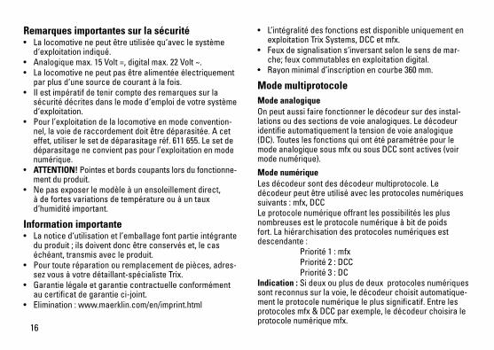
Remarques importantes sur la sécurité • Lalocomotivenepeutêtreutiliséequ‘aveclesystème
d‘exploitation indiqué.• Analogiquemax.15Volt=,digitalmax.22Volt~.• Lalocomotivenepeutpasêtrealimentéeélectriquement
par plus d‘une source de courant à la fois.• Ilestimpératifdetenircomptedesremarquessurla
sécurité décrites dans le mode d‘emploi de votre système d‘exploitation.
• Pour l’exploitation de la locomotive en mode convention-nel, la voie de raccordement doit être déparasitée. A cet effet, utiliser le set de déparasitage réf. 611 655. Le set de déparasitage ne convient pas pour l’exploitation en mode numérique.
• ATTENTION! Pointes et bords coupants lors du fonctionne-ment du produit.
• Nepasexposerlemodèleàunensoleillementdirect,à de fortes variations de température ou à un taux d‘humidité important.
Information importante• Lanoticed‘utilisationetl’emballagefontpartieintégranteduproduit;ilsdoiventdoncêtreconservéset,lecaséchéant, transmis avec le produit.
• Pourtouteréparationouremplacementdepièces,adres-sez vous à votre détaillant-spécialiste Trix.
• Garantielégaleetgarantiecontractuelleconformémentau certificat de garantie ci-joint.
• Elimination:www.maerklin.com/en/imprint.html
• L’intégralitédesfonctionsestdisponibleuniquementenexploitation Trix Systems, DCC et mfx.
• Feuxdesignalisations‘inversantselonlesensdemar-che;feuxcommutablesenexploitationdigital.
• Rayonminimald’inscriptionencourbe360mm.
Mode multiprotocole Mode analogiqueOn peut aussi faire fonctionner le décodeur sur des instal-lations ou des sections de voie analogiques. Le décodeur identifie automatiquement la tension de voie analogique (DC). Toutes les fonctions qui ont été paramétrée pour le mode analogique sous mfx ou sous DCC sont actives (voir mode numérique).
Mode numériqueLes décodeur sont des décodeur multiprotocole. Le décodeur peut être utilisé avec les protocoles numériques suivants:mfx,DCCLe protocole numérique offrant les possibilités les plus nombreuses est le protocole numérique à bit de poids fort. La hiérarchisation des protocoles numériques est descendante: Priorité1:mfx Priorité2:DCC Priorité3:DCIndication : Si deux ou plus de deux protocoles numériques sont reconnus sur la voie, le décodeur choisit automatique-ment le protocole numérique le plus significatif. Entre les protocoles mfx & DCC par exemple, le décodeur choisira le protocole numérique mfx.

17
Indication : remarquez que toutes les fonctions ne peuvent pas être actionnées dans tous les protocoles numériques. Sous mfx et sous DCC, il est possible de procéder à quelques paramétrages de fonctions devant être actives dans le cadre de l’exploitation analogique.
Remarques relatives au fonctionnement en mode digital • Encequiconcernelaprocédurederéglagedesdivers
paramètres, veuillez vous référer au mode d‘emploi de votre centrale de commande multitrain.
• Lesvaleursparamétréesd’usinesontchoisiespourmfx de manière à garantir le meilleur comportement de roulement possible. Pour d’autres systèmes d’exploitation, ces valeurs dev-ront éventuellement être adaptées.
• L’exploitationaveccourantcontinudepolaritéinversedans les sections de freinage n’est pas possible avec le réglage d’usine. Si cette propriété est désirée, il faut alors renoncer à l’exploitation conventionnelle en cou-rantcontinu(CV29/Bit2=0).
Protocole mfx
Adressage • Aucuneadressen’estnécessaire,ledécodeurreçoittou-
tefois une identification unique et non équivoque (UID).• AvecsonUID,ledécodeurindiqueautomatiquement
à une station centrale ou à une station mobile qu’il est connecté.
• Nomencodeeenusine:Di3 624 NSB
Programmation• Lescaractéristiquespeuventêtreprogramméespar
l’intermédiaire de la couche graphique de la station cen-trale, voire en partie aussi au moyen de la station mobile.
• Touteslesconfigurationsvariables(CV)peuventêtreluesetprogramméesdefaçonréitérée.
• Laprogrammationpeutêtreréaliséesoitsurlavoieprincipale, soit sur la voie de programmation.
• Lesparamétragespardéfaut(paramétragesusine)peuvent être rétablis.
• Mappagedesfonctions:lesfonctionspeuventêtreaffectées à de quelconques touches de fonction au moyen de la station centrale (60212) (restreinte) et avec la station centrale 60213/60214/60215 (voir Aide au niveau de la station centrale).

18
Protocole DCC
Adressage• Adressepossibles:Courtes,longuesetadressesdetraction• Catégoried’adresse:
1 à 127 (adresses courtes, adresses de traction) 1 à 10239 (adresses longues)
• Chaqueadresseestprogrammablemanuellement.• L’adressebrèveoulongueestchoisieparl’intermédiaire
des CVs.• Uneadressedetractionutiliséedésactivel’adresse
standard.
Programmation• Lescaractéristiquespeuventêtremodifiéesdefaçon
réitérée par l’intermédiaire des variables de configuration (CVs).
• Touteslesconfigurationsvariables(CV)peuventêtreluesetprogramméesdefaçonréitérée.
• Laprogrammationpeutêtreréaliséesoitsurlavoieprincipale, soit sur la voie de programmation.
• LesCVpeuventêtreprogramméeslibrement.LaPoM(programmation sur la voie principale) est possible uniquement pour les CV signalées dans le tableau des CV. La PoM doit être prise en charge par votre centrale (voir la notice d’utilisation de votre appareil).
• Lesparamétragespardéfaut(paramétragesusine)peuvent être rétablis.
• 14voire28/126cransdemarchesontparamétrables.
• Touteslesfonctionspeuventêtrecommutéesenfonctiondu mappage des fonctions (voir le descriptif des CVs).
• Pourtouteinformationcomplémentaire,voirletableaudes CVs, protocole DCC.
Il est recommandé, de réaliser la programmation, fonda-mentalement, sur la voie de programmation.
Fonctions logiques
Temporisation d’accélération et de freinage (TAF)• Lestempsd’accélérationetdefreinagepeuventêtre
définis indépendamment l’un de l’autre. • LadésactivationdelafonctionlogiqueTAFpeutêtre
affectée à n’importe quelle touche de fonction via le mappage de fonctions.

19
Fonctions commutables
Fanal éclairage activé Fonction f0 Fonction f0
Bruitage:Bruitd’exploitation — Fonction 2 Fonction f2 Fonction f2
Bruitage:trompe,signal — Fonction 3 Fonction f3 Fonction f3
ABV, désactivé — Fonction 4 Fonction f4 Fonction f4
Bruitage:Grincementdefreins — Fonction 5 Fonction f5 Fonction f5
Fanal cabine de conduite 2 éteint * — Fonction 6 Fonction f6 Fonction f6
Bruitage:SiffletContrôleur — Fonction 7 Fonction f7 Fonction f7
Fanal cabine de conduite 1 éteint * — Fonction 8 Fonction f8 Fonction f8
Bruitage:Siffletpourmanœuvre — — Fonction f9 Fonction f9
Vitessedemanœuvre — — Fonction f10 Fonction f10
Eclairage de la cabine de conduite 1 — — Fonction f11 Fonction f11
Eclairage de la cabine de conduite 2 — — Fonction f12 Fonction f12
FeudemanœuvredoubleA — — f0 + f6 + f8 f0 + f6 + f8
STOP mobile station
1 5 f0 f8 f0f8f0 - f3 f4 - f7
* Uniquement en combinaison avec Fanal éclairage

20
CV Affectation DCC Valeur Parm. Usine
1 Adresse 1 - 127 3 2 PoM Vitesse minimale 0 - 255 153 PoM Temporisation d‘accélération 0 - 255 154 PoM Temporisation de freinage 0 - 255 155 PoM Vitesse maximale 0 - 255 2088 Réinitialisation d’usine/identification du fabricant 8 131
13 PoM Fonctions F1 - F8 en mode analogique 0 - 255 014 PoM Fonctions F9 - F15 et éclairage en mode analogique 0 - 255 117 Adresse étendue (partie supérieure) CV29,Bit5=1 19218 Adresse étendue (partie inférieure) CV29,Bit5=1 12819 Adresse traction 0 - 255 021 PoM Fonctions F1 - F8 pour traction 0 - 255 022 PoM Fonctions F9 - F15 et éclairage traction 0 - 255 0
29 PoM
Bit0:InversiondusensdemarcheBit1:Nombredecransdemarche14ou28/128*Bit2:ExploitationDCCavecsectiondefreinage(exploitation analogique impossible) Bit5:Adressecourte/longue
0 / 1 0 / 2 0 / 4
0 / 32
0, 1, 2, 3, 4, 5, 6, 7, 32, 34, 35, 36,
37, 38, 396
63 PoM Volume 0 - 255 255
* Pour éviter tout dysfonctionnement, les crans de marche sur le décodeur de loco doivent impérativement coïncider avec ceux de l’appareil de commande.

21
Veiligheidsvoorschriften• Delocmagalleenmeteendaarvoorbestemdbedrijfssys-
teem gebruikt worden.• Analoogmax.15Volt=,digitaalmax.22Volt~.• Delocmagnietvanuitmeerdanéénstroomvoorziening
gelijktijdig gevoed worden.• Leesookaandachtigdeveiligheidsvoorschrifteninde
gebruiksaanwijzing van uw bedrijfssysteem. • Voorhetconventionelebedrijfmetdelocdientde
aansluitrail te worden ontstoort. Hiervoor dient men de ontstoor-set 611 655 te gebruiken. Voor het digitale bedrijf is deze ontstoor-set niet geschikt.
• OPGEPAST! Functionele scherpe kanten en punten.• Stelhetmodelnietblootaanindirectezonnestraling,
sterke temperatuurwisselingen of hoge luchtvochtigheid.
Belangrijke aanwijzing• Degebruiksaanwijzingendeverpakkingzijneenbe-
standdeel van het product en dienen derhalve bewaard en meegeleverd te worden bij het doorgeven van het product.
• VoorreparatiesenonderdelenkuntzichtotUwTrixhandelaar wenden.
• Vrijwaringengarantieovereenkomstighetbijgevoegdegarantiebewijs.
• Afdanken:www.maerklin.com/en/imprint.html• Devolledigetoegangtotallefunctiesisalleenmogelijk
met Trix Systems, DCC of met mfx bedrijf.• Ingebouwde,rijrichtingsafhankelijkefrontverlichtingisin
het digitaalsysteem schakelbaar.
• Minimaleteberijdenradius:360mm.
MultiprotocolbedrijfAnaloogbedrijfDe decoder kan ook op analoge modelbanen of spoortra-jecten gebruikt worden. De decoder herkent de analoge gelijkspanning (DC) automatisch en past zich aan de analoge railspanning aan. Alle functies die onder mfx of DCC voor het analoge bedrijf zijn ingesteld, worden geactiveerd (zie digitaalbedrijf).
DigitaalbedrijfDe Decoder is een multiprotocoldecoder. De decoder kan onderdevolgendedigitaleprotocolleningezetworden:mfx,DCC. Het digitaalprotocol met de meeste mogelijkheden is het primaire digitaalprotocol. De volgorde van de digitaalproto-collenisafnemendinmogelijkheden: Prioriteit1:mfx Prioriteit2:DCC Prioriteit3:DCOpmerking: Als er twee of meer digitale protocollen op de rails worden herkend, dan neemt de decoder automa-tischhethoogwaardigsteprotocolover;bijv.wordmfx&DCC herkend, dan wordt het mfx signaal door de decoder overgenomen.Opmerking: let er op dat niet alle functies in alle digitaal-protocollen mogelijk zijn. Onder mfx of DCC kunnen enkele instellingen, welke in analoogbedrijf werkzaam moeten zijn, ingesteld worden.
22
Aanwijzingen voor digitale besturing • Hetopdejuistewijzeinstellenvandediverseparame-
ters staat beschreven in de handleiding van uw digitale Centrale.
• Fabrieksmatigzijndewaardenvoormfxzoingesteltdatoptimale rijeigenschappen gegarandeerd zijn. Voor andere bedrijfssystemen moeten eventueel aanpas-singen uitgevoerd worden.
• Hetbedrijfmettegengepooldegelijkspanningindeafrem-sectie is met de fabrieksinstelling niet mogelijk. Indien deze eigenschap wenselijk is, dan moet worden afgezien van hetconventioneelgelijkstroombedrijf(CV29/Bit2=0).
Mfx-protocol
Adressering • Eenadresisnietnodig,elkedecoderheefteenéénmalig
en éénduidig kenmerk (UID).• DedecodermeldtzichvanzelfaanbijhetCentralStation
of Mobile Station met zijn UID.• Naamafdefabriek:Di3 624 NSB
Programmering • Deeigenschappenkunnenm.b.v.hetgrafischescherm
op het Central Station resp. deels ook met het Mobile Station geprogrammeerd worden.
• Alleconfiguratievariabelen(CV)kunnenvakergelezenen geprogrammeerd worden.
• Deprogrammeringkanzowelophethoofdspooralsophet programmeerspoor gebeuren.
• Dedefault-instellingen(fabrieksinstelling)kunnenweerhersteld worden.
• Functiemapping:functieskunnenmetbehulpvanhetCentral Station 60212 (met beperking) en met het Central Station 60213/60214/60215 aan elke gewenste functietoets worden toegewezen (zie het helpbestand in het Central Station).

23
DCC-protocol
Adressering • Mogelijkeadressen:kort,langentractieadres• Adresbereik:
1 – 127 (kort adres, tractieadres) 1 – 10239 (lange adres)
• Elkadresishandmatigprogrammeerbaar.• KortoflangadreswordtviadeCVgekozen.• Eentoegepasttractieadresdeactiveerthetstandaardad-
res.
Programmering• Deeigenschappenvandedecoderkunnenviadeconfi-
guratie variabelen (CV) vaker gewijzigd worden.• DeCV-nummersendeCV-waardenwordendirectinge-
voerd.• DeCV’skunnenvakergelezenengeprogrammeerd
worden (programmering op het programmeerspoor).• DeCVskunnennaarwensgeprogrammeerdworden.
PoM (Programmering op het hoofdspoor) is alleen moge-lijk bij de in de CV-tabel gemerkte CV. PoM moet door uw centrale ondersteund worden (zie de gebruiksaanwijzing van uw centrale).
• Dedefault-instellingen(fabrieksinstelling)kunnenweerhersteld worden.
• 14resp.28/126rijstappeninstelbaar.• Allefunctieskunnenovereenkomstigdefunctiemapping
geschakeld worden (zie CV-beschrijving).• Voorverdereinformatie,ziedeCV-tabelDCC-protocol.Het is aan te bevelen om het programmeren alleen op het
programmeerspoor uit te voeren.
Fysieke functies
Optrek en afremvertraging• Deoptrek-enafremvertragingkunnenonafhankelijkvan
elkaar ingesteld worden. • DelogischeuitschakelfunctieABV(optrek-enafremver-
traging) kan met de functiemapping aan elke gewenste functietoets toegewezen worden.
24
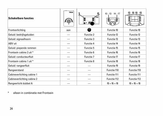
Schakelbare functies
Frontverlichting aan Functie f0 Functie f0
Geluid:bedrijfsgeluiden — Functie 2 Functie f2 Functie f2
Geluid:signaalhoorn — Functie 3 Functie f3 Functie f3
ABV uit — Functie 4 Functie f4 Functie f4
Geluid:piependeremmen — Functie 5 Functie f5 Functie f5
Frontsein cabine 2 uit * — Functie 6 Functie f6 Functie f6
Geluid:conducteurfluit — Functie 7 Functie f7 Functie f7
Frontsein cabine 1 uit * — Functie 8 Functie f8 Functie f8
Geluid:rangeerfluit — — Functie f9 Functie f9
Rangeerstand — — Functie f10 Functie f10
Cabineverlichting cabine 1 — — Functie f11 Functie f11
Cabineverlichting cabine 2 — — Functie f12 Functie f12
Rangeerlicht dubbel A — — f0 + f6 + f8 f0 + f6 + f8
STOP mobile station
1 5 f0 f8 f0f8f0 - f3 f4 - f7
* alleen in combinatie met Frontsein
25
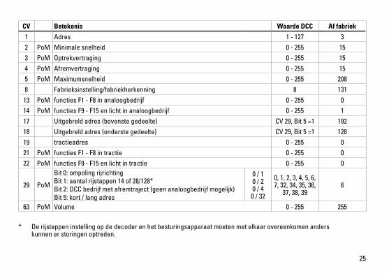
* De rijstappen instelling op de decoder en het besturingsapparaat moeten met elkaar overeenkomen anders kunnen er storingen optreden.
CV Betekenis Waarde DCC Af fabriek
1 Adres 1 - 127 3 2 PoM Minimale snelheid 0 - 255 153 PoM Optrekvertraging 0 - 255 154 PoM Afremvertraging 0 - 255 155 PoM Maximumsnelheid 0 - 255 2088 Fabrieksinstelling/fabriekherkenning 8 131
13 PoM functies F1 - F8 in analoogbedrijf 0 - 255 014 PoM functies F9 - F15 en licht in analoogbedrijf 0 - 255 117 Uitgebreld adres (bovenste gedeelte) CV29,Bit5=1 19218 Uitgebreld adres (onderste gedeelte) CV29,Bit5=1 12819 tractieadres 0 - 255 021 PoM functies F1 - F8 in tractie 0 - 255 022 PoM functies F9 - F15 en licht in tractie 0 - 255 0
29 PoM
Bit0:ompolingrijrichtingBit1:aantalrijstappen14of28/128*Bit2:DCCbedrijfmetafremtraject(geenanaloogbedrijfmogelijk)Bit5:kort/langadres
0 / 1 0 / 2 0 / 4
0 / 32
0, 1, 2, 3, 4, 5, 6, 7, 32, 34, 35, 36,
37, 38, 396
63 PoM Volume 0 - 255 255
26
27
2
1 1

28
29
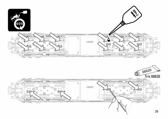
Trix 66626
40h

30
5
19
19
2
22
22
1919
8
8
915 21
2414
16
12
20
2323 17
21
23
13
24
10
10
2
3
3
19
19
12
21
6
1415
18
18
18
18
23
21
6
16
20
11
19
7
2
1
19194
17D
etai
ls d
er D
arst
el-
lung
kön
nen
von
dem
M
odel
l abw
eich
en.

31
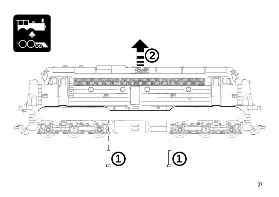
1 Bullauge E242 071 2 Puffer E246 197 3 Griffstangen E242 338 4 Haken, Bremsschlauch E246 199 5 Scheibenwischer E242 098 6 Tritt E242 335 7 Decoder 245 756 8 Lautsprecher E246 205 9 Motor E242 924 10 Schneckenwelle,Kardanwelle E246 215 11 Kurzkupplung E701 630 12 Beleuchtung E242 376 13 Kupplung E246 216 14 Schraube E244 715 15 Schürze E245 511 16 Drehgestell E245 754 17 Radschleifer E244 706 18 Haftreifen 7 154 19 Schraube E246 303 20 Schraube E246 304 21 Schraube E246 305 22 Schraube E246 306 23 Schraube E246 307 24 Schraube E246 308
Hinweis:EinigeTeilewerdennurohneodermitandererFarbgebung angeboten. Teile, die hier nicht aufgeführt sind, können nur im Rahmen einer Reparatur im Märklin-Reparatur-Service repariert werden.

Gebr. Märklin & Cie. GmbH Stuttgarter Straße 55 - 57 73033 Göppingen Germanywww.trix.de
245758/0115/Sm1MtÄnderungen vorbehalten
© Gebr. Märklin & Cie. GmbH
Due to different legal requirements regarding electro-magnetic compatibility, this item may be used in the USA only after separate certification for FCC com-pliance and an adjustment if necessary. Use in the USA without this certification is not permitted and absolves us of any liability. If you should want such certification to be done, please contact us – also due to the additional costs incurred for this.
www.maerklin.com/en/imprint.html