cxdi-50g / 50c - frank's hospital workshop · manual control no. : by8-2257-0e5 name of...
TRANSCRIPT

CCXXDDII--11 SSyysstteemm
CCaannoonn IInncc.. JJaappaann CCooppyyrriigghhtt ((CC)) CCaannoonn IInncc.. MMeeddiiccaall TTeecchhnniiccaall SSeerrvviiccee DDeepptt.. AAllll rriigghhttss RReesseerrvveedd..
CCXXDDII--5500GG // 5500CCSSeerrvviiccee MMaannuuaall
PPrriinntteedd bbyy CCaannoonn IInncc..MMaarr.. 22000077 RReevv..0055aa

Manual Control No. : BY8-2257-0E5 Name of Product : CXDI-50G/50C Distribution Control No. Issued on
Service Manual Introduction
This service manual belongs to a series of after-service guides Canon Inc. publishes as part of its comprehensive product quality guarantee program.
This service manual consists of seven chapters; General Information, Installation Guide, Feature Information, Repair Guide, Parts Catalog, Troubleshooting and Service Manual Report.
If the product undergoes a large modification, a new service manual of revised edition will be sent to you. In other cases, service manual report will be sent to you updates the manual.
Note 1:
This service manual is published by Canon Inc. in accordance with Article 6 (Furnishing the Referent Materials) of the Service Assignment Contract it has concluded with your company.
Note 2:
This service manual property of Canon Inc. and the company may seek to have it returned, depending on circumstances. You are expected to keep it until then.
Note 3:
You inquiries, suggestions etc. about the contents of this service manual should be addressed to:
Medical Products Technical Service Dept. Canon Inc. Headquarters 30-2, Shimomaruko 3-chome, Ohta-ku, Tokyo 146-8501, Japan
Caution Regarding Service This product was precisely assembled under strict manufacturing process control. There are several hazardous locations inside of this product. Careless work while the cover is removed can result in pinching fingers or cause electrical shock. Please perform the work with the following important points in mind:
1. Setup, Repair and Maintenance
In order to ensure safety, the best performance, setup, repair and maintenance work can only be performed by the technicians received the service training specified by Canon Inc. If there are order required certificates or restrictions specified by the law or ordinances, those regulations of the country must be observed.
2. Removing the external cover
When removing the cover during maintenance, repair, etc., perform the work after switching the power off. Never touch the device with wet hands, as there is a risk of electric shock.
3. Fuse
When replacing the fuse, first, resolve the reason of failure and then replace the fuse with the specified type. Never use a fuse other than the specified type.
4. Connecting the grounding wire
The provided ground wire must be connected to the ground terminal indoors. make sure that the device is properly grounded.
5. Alternation prohibition
Never modify the medical device in any way.
6. Waste control
The service provider is responsible for the disposal of used service parts, packing material, etc. resulting from the setup, repair or maintenance of the medical device However, the customer is responsible for the disposal of the medical device. Disposal activities must follow the regulations (=specially controlled industrial waste) of the country where the device is used.

VORSICHT Befolgen Sie die unten angegebenen Sicherheitsanweisungen. Mißachtung kann zu erletzungenoder Unfällen führen. 1.Zerlegung, Zusammenbau, Einstellung und Wartung Zerlegung, Zusammenbau, Einstellung und Wartung dürfen nur von einem Wartungstechniker durchgeführt werden, der an einem von Canon vorgeschriebenen Wartungslehrgang teilgenommen hat.
2.Entfernen von Abdeckungen Schalten Sie unbedingt die Stromversorgung des Instruments aus, bevor Sie die Abdeckungen zwecks Wartung und Reparatur entfernen. Vermeiden Sie auch eine Berührung des Instruments mit nassen Händen. Anderenfalls können Sie einen elektrischen Schlag erleiden, der zum Tod oder schwerer Verletzung führen kann.
3.Sicherung Wenn die Sicherung ausgewechselt werden muß, schalten Sie unbedingt die Stromversorgung des Instruments aus, und beheben Sie die Ursache für das Durchbrennen der Sicherung. Ersetzen Sie die Sicherung nur durch den vorgeschriebenen Typ. Anderenfalls kann es zu einem Brand oder elektrischen Schlag kommen.
4.Erdleiter Erden Sie das Instrument unbedingt an einer Schukosteckdose. Anderenfalls kann es zu einem Brand oder elektrischen Schlag durch Leckstrom kommen.
5.Umbau Jeder Umbau des Produktes ist strengstens untersagt, da dies zu einem Brand oder elektrischen Schlag führen kann.
6.Bewegliche Teile Dieses Instrument enthält bewegliche Teile. Führen Sie während der Bewegung der Teile keine unachtsame Tätigkeit aus. Anderenfalls können Sie verletzt werden.
7.Schnittstellenanschluß Wenn andere Geräte über den Schnittstellenanschluß an das Instrument angeschlossen werden, prüfen Sie nach dem Anschluß, daß der Leckstrom innerhalb des zulässigen Bereichs liegt.
8.Lithiumbatterie Ersetzen Sie die Lithiumbatterie nur durch den vorgeschriebenen Typ. Verbrauchte Batterien dürfen nicht ins Feuer geworfen und weder zerlegt noch geladen werden. Entsorgen Sie verbrauchte Batterien umweltschonend gemäß den Gesetzen oder Vorschriften des Landes, in dem das Instrument benutzt wird.

CCaauuttiioonn rreeggaarrddiinngg tthhee sseettuupp
According to the “IEC60601-1-1:2000”, devices installed in the patient environment are restricted to “electric medical devices conforming to IEC60601-1”.
The Control PC, operation unit, and the magnetic card reader, etc. options that are parts of the CXDI-C3S are classified under the data processing device standard (IEC60950), therefore these items should not be installed in the patient environment. Otherwise the Control PC is only classified in CXDI-C3S.
The patient environment described below is an example cited from the “IEC60601-1-1:2000” – the measurements are only guidelines. However, the “IEC60601-1-1:2000” example must be treated as the standard.
Therefore, the CXDI-C3S must be installed in a location further than the measurements below (outside of the patient environment).
*Areas where the patient moves (not only during imaging but when entering and leaving the room, etc.) are also considered as part of the patient environment, therefore the installation location should be determined upon consultation with the user regarding areas outside of the patient environment.
Example of patient environment
Note: The measurements are only guidelines.
CCXXDDII--5500GG // 5500CC
CCaannoonn IInncc.. JJaappaann CCooppyyrriigghhtt ((CC)) CCaannoonn IInncc.. MMeeddiiccaall TTeecchhnniiccaall SSeerrvviiccee DDeepptt.. AAllll rriigghhttss
RReesseerrvveedd..
11.. GGeenneerraall
PPrriinntteedd bbyy CCaannoonn IInncc.. FFeebb.. 22000066 RReevv..0033

Content
General ................................................................................................................................................1
1 CXDI-1 System Block Diagram ..........................................................................................................2
2 System Diagram...................................................................................................................................3
3 CXDI Image Processing.......................................................................................................................4
4 Specifications .......................................................................................................................................5

1. General
1
General CXDI-50G
Change of the image read-out method from the sensor was made to the former CXDI-50G. In the former CXDI-50G, Aux. Shift Register Driver (PCB-D-EP), Scanner with Main Scanner Driver (PCB-50A) and A/D Conversion (PCB-50AD) are located in the both sides of LANMIT. One panel is considered as two virtual panels, and image data was read out from both sides. However, in new CXDI-50G, Aux. Shift Register Driver (PCB-D-EP), Signal Read-out Circuit (PCB-50A) and the A/D Conversion (PCB-50AD) are located in one side of LANMIT and the image data was read from one side. Since the appearance of new CXDI-50G is the same as that of the former CXDI-50G, they are identified by changing the serial number of the main unit.
CXDI System Software Ver.6.4 and later
Clinic Software Ver.1.04 and later
7M 150001~ Serial number of main units 3M 250001~
CXDI-50C
Fluorescent substance of CXDI-50G has been changed to CsI from GOS in CXDI-50C so that the CXDI-50C can be ranked as the more superior performance model (high sensitivity model) than CXDI-50G. The read-out method of image data is read-out from both sides of LANMIT which is same as CXDI-50G.
Ver.6.4 and later 7M 100001~ CXDI System Software 3M 200001~
1. General
2
Operation Unit
RS232C
VGA
ID Unit (Option)
RS232C
Network Ethernet
(100/10bese-T)
AC120V±10% 60Hz 2A AC230V±10% 50/60Hz 1.5A
X-Ray Generator
Mouse
Power Box SPW
OUT PUT 1 Control/Signal
OUT PUT 2 Control/Signal
AC Power IN AC120V/230V CA1
CA6
CA7
CA8
Imaging Unit (CXDI-50G/50C)
Control/Signal
Control PC (CXDI-C3S) VGA
LAN2
AC Power IN
SCSI
SERIAL(COM3)
MOUSE
KEY BOARD
SERIAL(COM4)
Key Board
Printer
Image file device
Image diagnosis W/S
X-Ray I/F
CA2
LAN1
CA3
CA4
CA5
Remo.
SERIAL(COM1)
SERIAL(COM2)
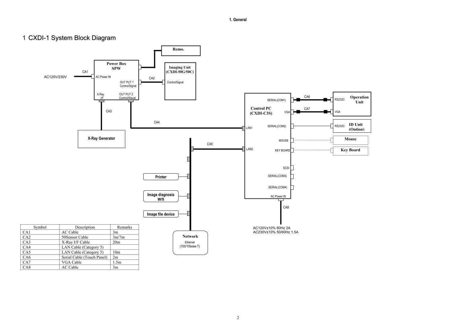
11 CCXXDDII--11 SSyysstteemm BBlloocckk DDiiaaggrraamm
Symbol Description Remarks CA1 AC Cable 3m CA2 50Sensor Cable 3m/7m CA3 X-Ray I/F Cable 20m CA4 LAN Cable (Category 5) CA5 LAN Cable (Category 5) 10m CA6 Serial Cable (Touch Panel) 2m CA7 VGA Cable 1.5m CA8 AC Cable 3m
1. General
3
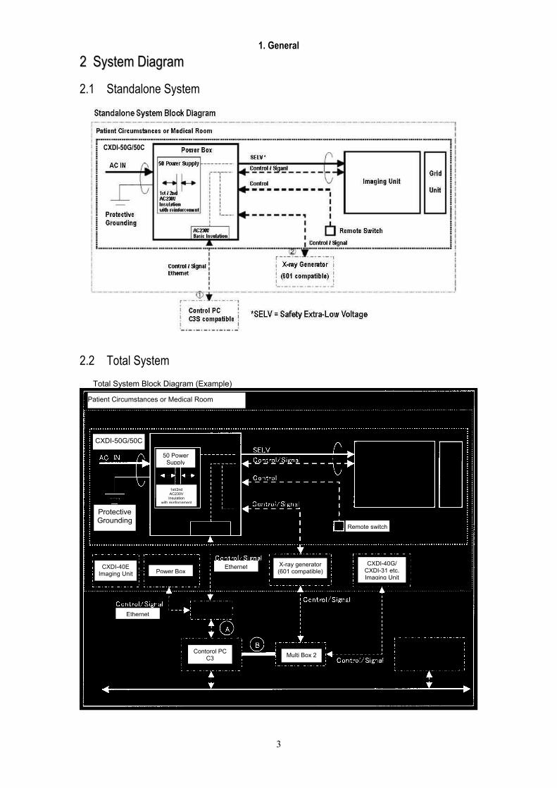
22 SSyysstteemm DDiiaaggrraamm
2.1 Standalone System
2.2 Total System
Total System Block Diagram (Example)
CXDI-50G/50C
Patient Circumstances or Medical Room
CXDI-50G/50C
Protective Grounding
POWER BOX
50 Power Supply
1st/2nd AC230V Insulation
with reinforcement
Imaging Unit Grid
Unit
AC230V Basic Insulation
Power Box CXDI-40E
Imaging Unit
Remote switch
Ethernet X-ray generator (601 compatible)
CXDI-40G/ CXDI-31 etc. Imaging Unit
Ethernet Network switch
Contorol PC C3 Multi Box 2
Image Examination WS Image File Equipment
Printer etc.
Ethernet
1. General
4
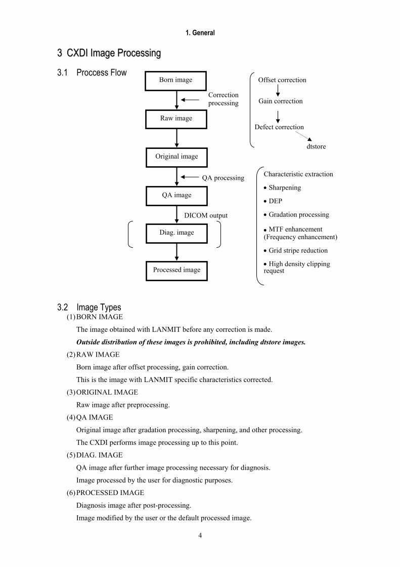
33 CCXXDDII IImmaaggee PPrroocceessssiinngg
3.1 Proccess Flow
3.2 Image Types (1) BORN IMAGE
The image obtained with LANMIT before any correction is made.
Outside distribution of these images is prohibited, including dtstore images.
(2) RAW IMAGE
Born image after offset processing, gain correction.
This is the image with LANMIT specific characteristics corrected.
(3) ORIGINAL IMAGE
Raw image after preprocessing.
(4) QA IMAGE
Original image after gradation processing, sharpening, and other processing.
The CXDI performs image processing up to this point.
(5) DIAG. IMAGE
QA image after further image processing necessary for diagnosis.
Image processed by the user for diagnostic purposes.
(6) PROCESSED IMAGE
Diagnosis image after post-processing.
Image modified by the user or the default processed image.
Born image
Raw image
Original image
QA image
Diag. image
Processed image
Correction processing
QA processing
Offset correction
Gain correction
Defect correction
dtstore
Characteristic extraction • Sharpening • DEP • Gradation processing • MTF enhancement
(Frequency enhancement) • Grid stripe reduction • High density clipping request
DICOM output
1. General
5
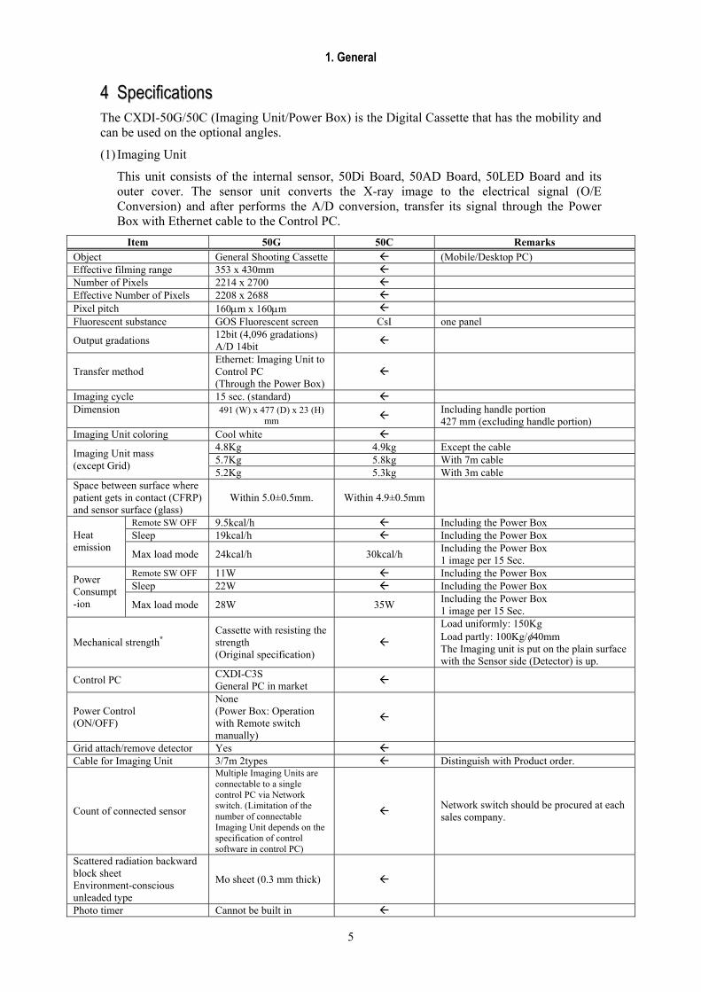
44 SSppeecciiffiiccaattiioonnss The CXDI-50G/50C (Imaging Unit/Power Box) is the Digital Cassette that has the mobility and can be used on the optional angles.
(1) Imaging Unit
This unit consists of the internal sensor, 50Di Board, 50AD Board, 50LED Board and its outer cover. The sensor unit converts the X-ray image to the electrical signal (O/E Conversion) and after performs the A/D conversion, transfer its signal through the Power Box with Ethernet cable to the Control PC.
Item 50G 50C Remarks Object General Shooting Cassette (Mobile/Desktop PC) Effective filming range 353 x 430mm Number of Pixels 2214 x 2700 Effective Number of Pixels 2208 x 2688 Pixel pitch 160µm x 160µm Fluorescent substance GOS Fluorescent screen CsI one panel
Output gradations 12bit (4,096 gradations) A/D 14bit
Transfer method Ethernet: Imaging Unit to Control PC (Through the Power Box)
Imaging cycle 15 sec. (standard) Dimension 491 (W) x 477 (D) x 23 (H)
mm Including handle portion 427 mm (excluding handle portion)
Imaging Unit coloring Cool white 4.8Kg 4.9kg Except the cable 5.7Kg 5.8kg With 7m cable Imaging Unit mass
(except Grid) 5.2Kg 5.3kg With 3m cable
Space between surface where patient gets in contact (CFRP) and sensor surface (glass)
Within 5.0±0.5mm. Within 4.9±0.5mm
Remote SW OFF 9.5kcal/h Including the Power Box Sleep 19kcal/h Including the Power Box Heat
emission Max load mode 24kcal/h 30kcal/h Including the Power Box
1 image per 15 Sec. Remote SW OFF 11W Including the Power Box Sleep 22W Including the Power Box Power
Consumpt-ion Max load mode 28W 35W Including the Power Box
1 image per 15 Sec.
Mechanical strength* Cassette with resisting the strength (Original specification)
Load uniformly: 150Kg Load partly: 100Kg/φ40mm The Imaging unit is put on the plain surface with the Sensor side (Detector) is up.
Control PC CXDI-C3S General PC in market
Power Control (ON/OFF)
None (Power Box: Operation with Remote switch manually)
Grid attach/remove detector Yes Cable for Imaging Unit 3/7m 2types Distinguish with Product order.
Count of connected sensor
Multiple Imaging Units are connectable to a single control PC via Network switch. (Limitation of the number of connectable Imaging Unit depends on the specification of control software in control PC)
Network switch should be procured at each sales company.
Scattered radiation backward block sheet Environment-conscious unleaded type
Mo sheet (0.3 mm thick)
Photo timer Cannot be built in

1. General
6
Item 50G 50C Remarks
Imaging restriction (Imaging Prohibition)
When the internal temperature of Imaging Unit is above 49 degree Celsius, its state is changed to sleep mode. And the Imaging prohibition will be continued when the internal temperature is below 48 degree Celsius.
INDICATION BUSY SENSOR POWER Color Orange Green Blue
Imaging unit is off Off Off Off
Imaging unit is on -- Off On
Preparing imaging -- Blinking *1 On
Imaging preparation complete
-- Off On
Error status -- Blinking *2 On Communi- cating Blinking *3 -- On
Initialization (when startup)
-- Blinking *4 On
Network not set (when startup)
-- Blinking *5 On
User interface
Single type LED Off: Imaging unit power is off On in orange: Imaging unit power is on (unable to perform imaging) Blinking in green: Preparing imaging/error status On in green: Imaging preparation is complete
*1: Turns on and off for 0.5 seconds each *2: Turns on and off twice for 0.5 seconds, then
turns off for 0.5 seconds *3: Turns on and off randomly *4: Fades in for 1 second and fades out for 1
second *5: Fades in for 2 seconds, and then turns off

1. General
7
(2)Power Box
This unit consists of 40XRAY Board, 50Power Supply and its outer cover.
The function; the signal transition between Imaging unit and Control PC, the interface to the X-ray generator equipment and power supply to the Imaging unit has been implemented.
Item Content Remarks Communication interface standard IEEEE* 802.3u (100BASE-TX) Connector type: RJ45
Communication method Asynchronous serial communication method
Data length: 10bit Data rate: 15.625 kHz
Power supply AC 100-120V±10% 50/60Hz 1.5A AC 200-240V±10% 50/60Hz 0.8A
Reference CXDI-50G Power supply Rated Voltage: AC 100-120V (AC 85-132V) AC 200-240V (AC170-264V)
Mass 4.2 Kg
Dimension 358(W) x 200(D) x 65(H)* mm Except bottom rubber parts (With bottom rubber parts: 75mm)
(3) Environment rated parameters
Item Content Remarks Operating temperature +5 to +35°C Operating humidity 30 to 75% RH
Must be without dewing
Keeping or Transporting
Temperature: -30 to +50°C Humidity: 10 to 60% RH Atmospheric pressure: 700 to 1060 hPa
* IEEE: Institute of Electrical and Electronic Engineers


CCXXDDII--5500GG // 5500CC
CCaannoonn IInncc.. JJaappaann CCooppyyrriigghhtt ((CC)) CCaannoonn IInncc.. MMeeddiiccaall TTeecchhnniiccaall SSeerrvviiccee DDeepptt.. AAllll rriigghhttss
RReesseerrvveedd..
22.. IInnssttaallllaattiioonn MMaannuuaall
PPrriinntteedd bbyy CCaannoonn IInncc..FFeebb.. 22000077 RReevv..0044

Content
1 Caution during the installation .............................................................................................. 1
2 Product Configuration ........................................................................................................... 2
3 Packing Diagram ................................................................................................................... 5
4 Installation Procedures .......................................................................................................... 7
4.1 Lists of Tool Needed for Installation ............................................................................. 7
4.2 System Installation Procedures ...................................................................................... 8
5 Installation ........................................................................................................................... 10
5.1 Connection to each unit................................................................................................ 10
5.2 Starting up and shutting down the System................................................................... 16
5.3 X-ray Controller Interface............................................................................................ 17
5.4 Network Settings 1....................................................................................................... 23 5.5 Setting the Fixed ROI Areas......................................................................................................26
5.6 Adjusting the photo timer ..........................................................................................................29
5.7 Settings......................................................................................................................... 31 5.8 Adjusting the Alignment............................................................................................................87
5.9 Image Quality............................................................................................................... 93
5.10 Post-installation checks................................................................................................ 95
6 Dimension............................................................................................................................ 97
2. Installation Manual
- 1 -
11 CCaauuttiioonn dduurriinngg tthhee iinnssttaallllaattiioonn Please pay attention to the followings when installing the system.
(1) If the equipment is hoisted, lowered or transport, it must be supported at both sides by a minimum of two people so there is no danger of it falling.
(2) If a forklift, etc. is used to transport the equipment, make sure there is nothing that could impede the forklift on its route to the final destination.
(3) When installing the equipment, be sure the site meets the following criteria:
1) There must be no dripping water in the area.
2) The environment must be free of harmful elements such as humid or acidic air, air with a saline or sulfur content, where there is poor ventilation or where air pressure or temperature is unusual.
3) The equipment must not be placed at an angle or subjected to vibration or shock (this includes during transportation).
4) The equipment must not be kept where chemical products are stored or where gasses are generated.
5) The site’s power supply must be of the correct voltage and frequency for the equipment.
6) The site must be connected to a fully earthed cable with sufficient ground resistance to meet standard values.
(4) After installation, be sure to dispose of waste product packaging with care and with full respect for the environment.
2. Installation Manual
- 2 -
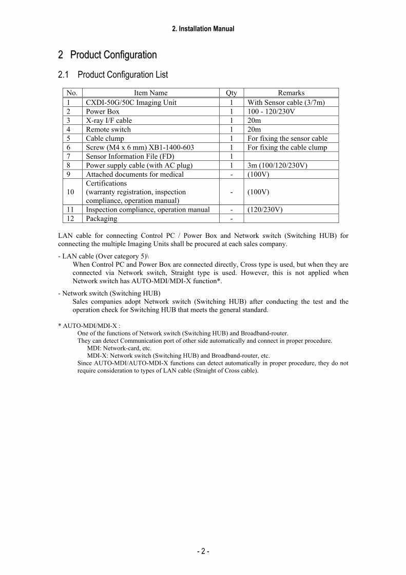
22 PPrroodduucctt CCoonnffiigguurraattiioonn
2.1 Product Configuration List
No. Item Name Qty Remarks 1 CXDI-50G/50C Imaging Unit 1 With Sensor cable (3/7m) 2 Power Box 1 100 - 120/230V 3 X-ray I/F cable 1 20m 4 Remote switch 1 20m 5 Cable clump 1 For fixing the sensor cable 6 Screw (M4 x 6 mm) XB1-1400-603 1 For fixing the cable clump 7 Sensor Information File (FD) 1 8 Power supply cable (with AC plug) 1 3m (100/120/230V) 9 Attached documents for medical - (100V)
10 Certifications (warranty registration, inspection compliance, operation manual)
- (100V)
11 Inspection compliance, operation manual - (120/230V) 12 Packaging -
LAN cable for connecting Control PC / Power Box and Network switch (Switching HUB) for connecting the multiple Imaging Units shall be procured at each sales company.
- LAN cable (Over category 5)\ When Control PC and Power Box are connected directly, Cross type is used, but when they are connected via Network switch, Straight type is used. However, this is not applied when Network switch has AUTO-MDI/MDI-X function*.
- Network switch (Switching HUB) Sales companies adopt Network switch (Switching HUB) after conducting the test and the operation check for Switching HUB that meets the general standard.
* AUTO-MDI/MDI-X :
One of the functions of Network switch (Switching HUB) and Broadband-router. They can detect Communication port of other side automatically and connect in proper procedure.
MDI: Network-card, etc. MDI-X: Network switch (Switching HUB) and Broadband-router, etc.
Since AUTO-MDI/AUTO-MDI-X functions can detect automatically in proper procedure, they do not require consideration to types of LAN cable (Straight of Cross cable).

2. Installation Manual
- 3 -
2.2 Configuration
No. 1 No. 2 Name CXDI-50G/50CImaging Unit Name Power Box Qty 1 Qty 1
Remarks 3/7m Remarks I/F and Power supply (3/7m)
No. 3 No. 4 Name X-ray I/F cable Name Remote switch Qty 1 Qty 1
Remarks Connection with X-ray generator Remarks Power Box power source
ON/OFF
No. 5 No. 6
Name Cable clump Name Screw (M4 x 6mm) Qty 1 Qty 1
Remarks For fixing the sensor cable Remarks For fixing the cable clump
2. Installation Manual
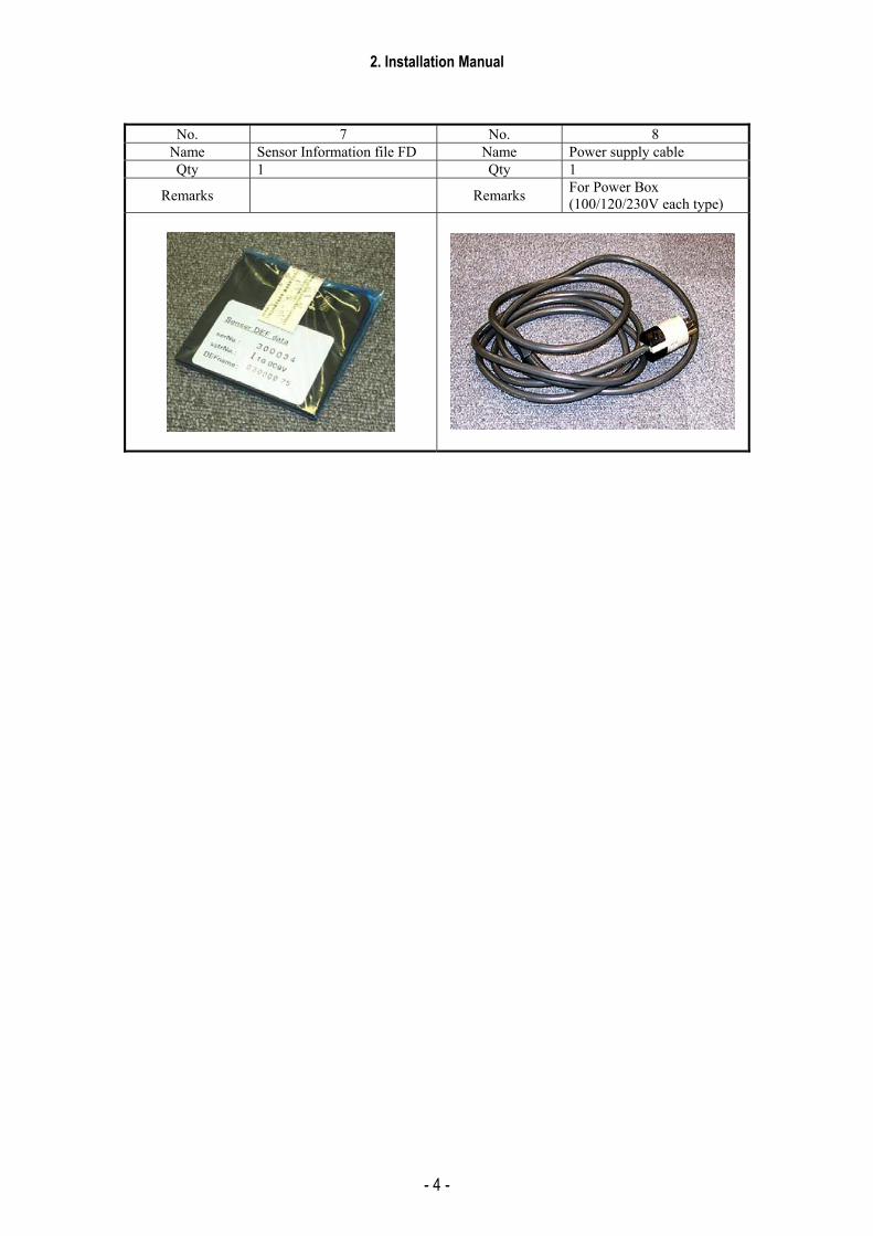
- 4 -
No. 7 No. 8 Name Sensor Information file FD Name Power supply cable Qty 1 Qty 1
Remarks Remarks For Power Box (100/120/230V each type)
2. Installation Manual
- 5 -
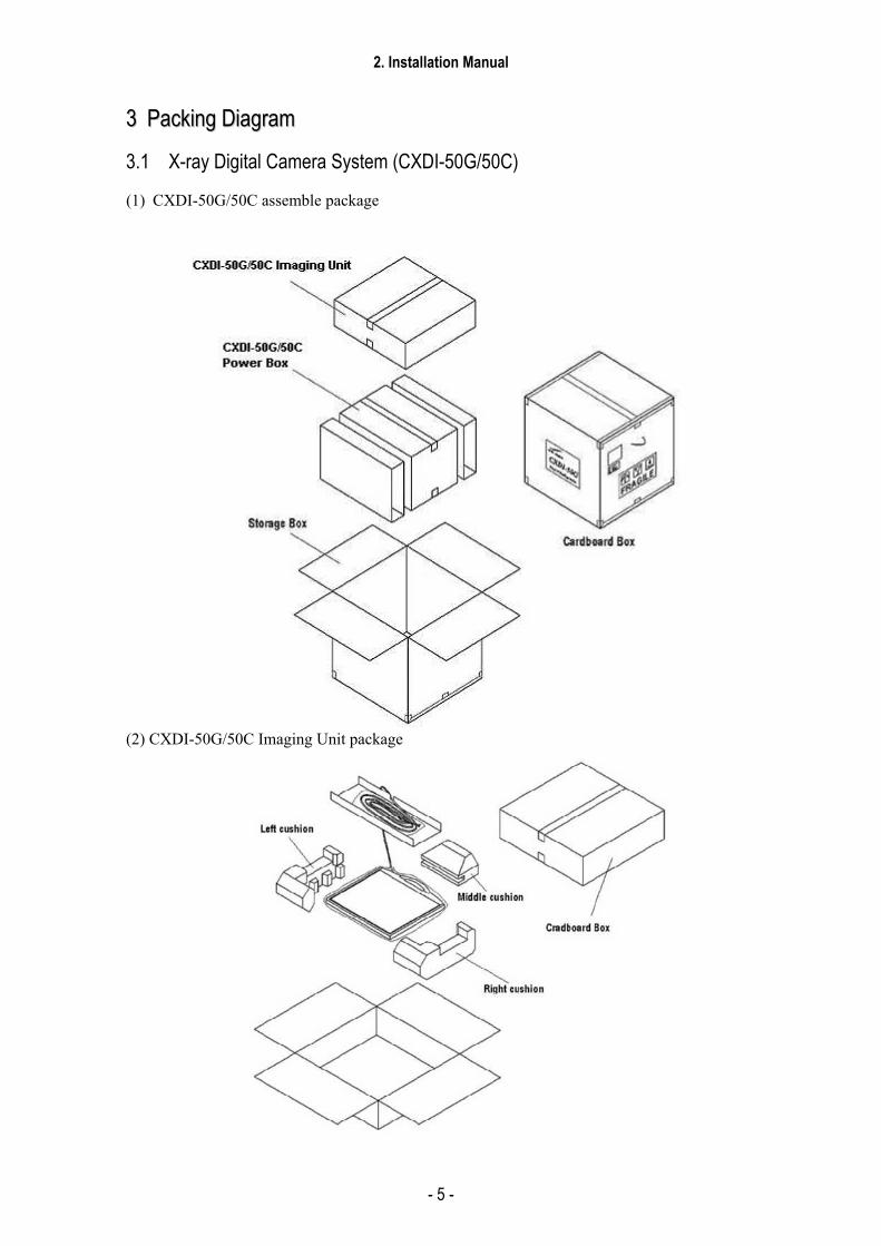
33 PPaacckkiinngg DDiiaaggrraamm
3.1 X-ray Digital Camera System (CXDI-50G/50C)
(1) CXDI-50G/50C assemble package
(2) CXDI-50G/50C Imaging Unit package

2. Installation Manual
- 6 -
(3) Power Box assemble package
(4) Grid (optional)
2. Installation Manual
- 7 -
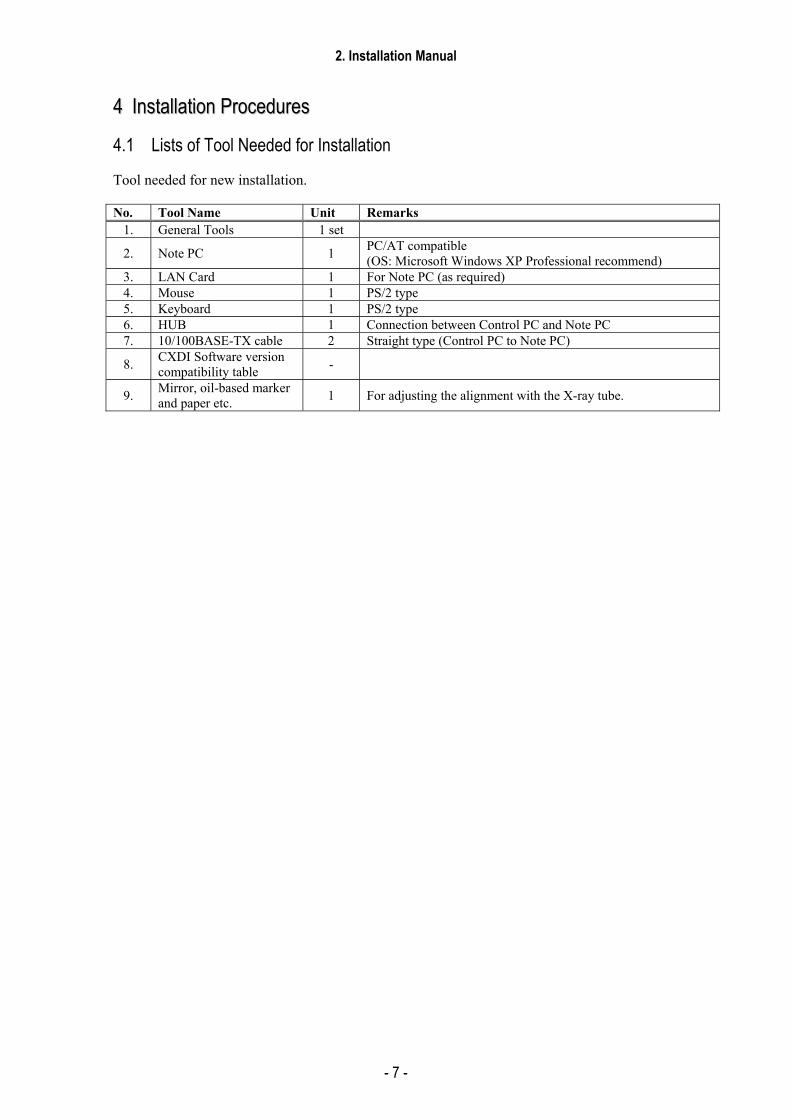
44 IInnssttaallllaattiioonn PPrroocceedduurreess
4.1 Lists of Tool Needed for Installation
Tool needed for new installation.
No. Tool Name Unit Remarks 1. General Tools 1 set
2. Note PC 1 PC/AT compatible (OS: Microsoft Windows XP Professional recommend)
3. LAN Card 1 For Note PC (as required) 4. Mouse 1 PS/2 type 5. Keyboard 1 PS/2 type 6. HUB 1 Connection between Control PC and Note PC 7. 10/100BASE-TX cable 2 Straight type (Control PC to Note PC)
8. CXDI Software version compatibility table -
9. Mirror, oil-based marker and paper etc. 1 For adjusting the alignment with the X-ray tube.

2. Installation Manual
- 8 -
4.2 System Installation Procedures
No. Step Conditions and Checkpoints Reference Section 1 Unpacking and checking the
product’s constituent parts -There must be no missing parts, damage, dents, etc. -There must no color changes in the shock sensor.
2 Connect the Imaging Unit and the Power Box
-Handle the instrument carefully, as it may be damaged if something is hit against it, dropped or receives the strong jolt. -The cable must be routed in such a way that no unreasonable loads are brought to bear upon them.
3 Connect the Power Box and the Control PC
-The cable must be routed in such a way that no unreasonable loads are brought to bear upon them.
4 Connect the Power Box and the X-ray generators
-The manufacturer of the X-ray generators must be asked to handle the connections with the generators.
5 Check date and time - Date and time must be changed according to the area where the instrument is installed.
“(1) Checking and Setting the Date and Time” in section 5.6.
6 Check the software program’s version
-The compatibility of the sensor unit and the Control PC must be checked on the compatibility list, and the software program must be installed or upgrade as required.
“(2) Checking the Firmware Version” in section 5.6.
7 Identifying the Imaging Unit (input the sensor serial numbers)
“(6) Identifying the Sensor Units” in section 5.6.
8 Enter control PC serial number.
“(7) Entering Control PC Serial Number” in section 5.6.
(9) Adjusting the timing with X-ray generator
-No required usually.
10 Calibration -No error must be displayed. Operation Manual 11 Setting the Fixed ROI Areas If necessary, set the ROI area. 12 Set exposure parameter table -Set it in consultation with the technician. “(8) Table Setup
Setting” in section 5.6. 13 Set annotation -Set it in consultation with the technician. “(9) Performing the
Annotation Setting” in section 5.6.
14 Connect the network and set the output destination
“(10) Network Connections” in section 5.6.
15 Startup settings “(5) Set Up Startup Menu” in section 5.6.
16 Exposure testing -The data must be sent to the printer and storage and the image quality must be checked.
Section 5.7 Image Quality.
17 Check the linearity of the transferred image density.
“(11) Linearity Check Image Density” in section 5.6.
18 Operation unit Gamma correction
“(12) Operation Unit Gamma Correction” in section 5.6.
19 Body parts settings -The engineer in charge must be consulted prior to perform these settings.
Operation Manual
20 Check and set the system settings.
-The engineer in charge must be consulted prior to perform these settings.
Each section in section 5.6 Settings.
21 Total adjustments and delete the unnecessary data.
-Conform according to the check sheet. -Delete the unnecessary data.
Section 5.8 Post-installation check.
22 Cleaning

2. Installation Manual
- 9 -
23 Explain the operation to the user
Operation Manual
24 Final parameter adjustment -The engineer in charge must be consulted prior narrowing down the adjustments to the final values.
Operation Manual
25 Inserting the backup floppy disk.
-It must be confirmed at re-start that backup files have been made. -No necessary for the system installed in vehicles.
“(15) Backing up Setting Data to FD” in section 5.6.
26 Back up valuable data “(14) Backing Up when Installing” in section 5.6.
2. Installation Manual
- 10 -
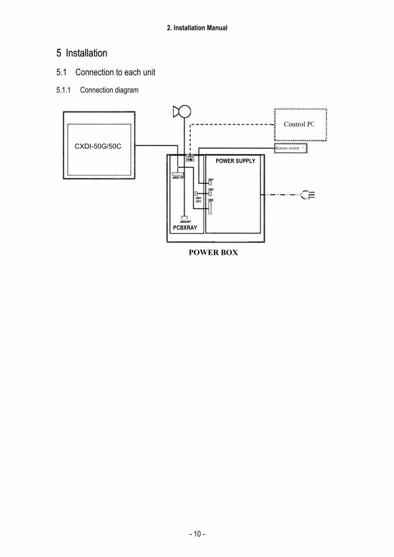
55 IInnssttaallllaattiioonn
5.1 Connection to each unit
5.1.1 Connection diagram
CXDI-50G
POWER BOX
PCBXRAY
POWER SUPPLY
Control PC
Remote switch CXDI-50G/50C
2. Installation Manual
- 11 -
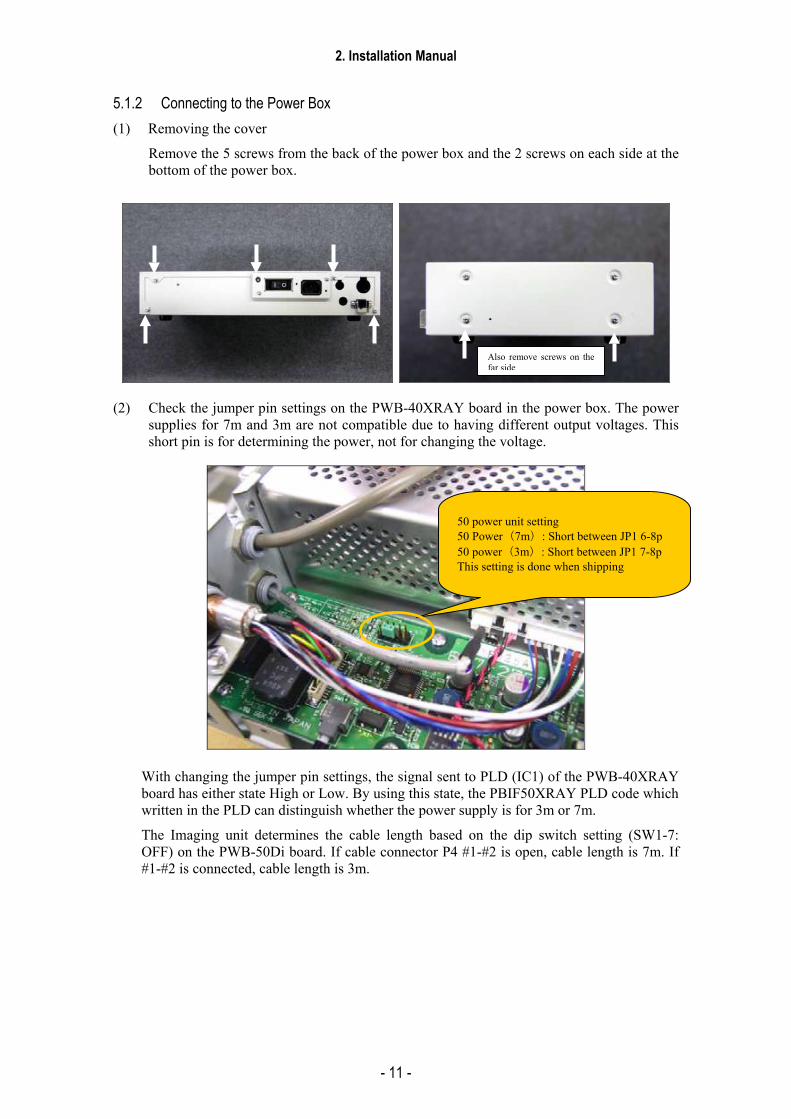
5.1.2 Connecting to the Power Box (1) Removing the cover
Remove the 5 screws from the back of the power box and the 2 screws on each side at the bottom of the power box.
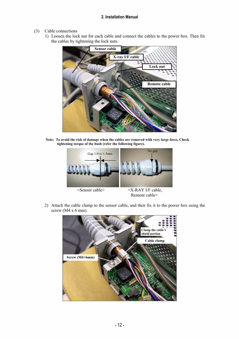
(2) Check the jumper pin settings on the PWB-40XRAY board in the power box. The power
supplies for 7m and 3m are not compatible due to having different output voltages. This short pin is for determining the power, not for changing the voltage.
With changing the jumper pin settings, the signal sent to PLD (IC1) of the PWB-40XRAY board has either state High or Low. By using this state, the PBIF50XRAY PLD code which written in the PLD can distinguish whether the power supply is for 3m or 7m.
The Imaging unit determines the cable length based on the dip switch setting (SW1-7: OFF) on the PWB-50Di board. If cable connector P4 #1-#2 is open, cable length is 7m. If #1-#2 is connected, cable length is 3m.
Also remove screws on thefar side
50 power unit setting 50 Power(7m): Short between JP1 6-8p50 power(3m): Short between JP1 7-8pThis setting is done when shipping
2. Installation Manual
- 12 -
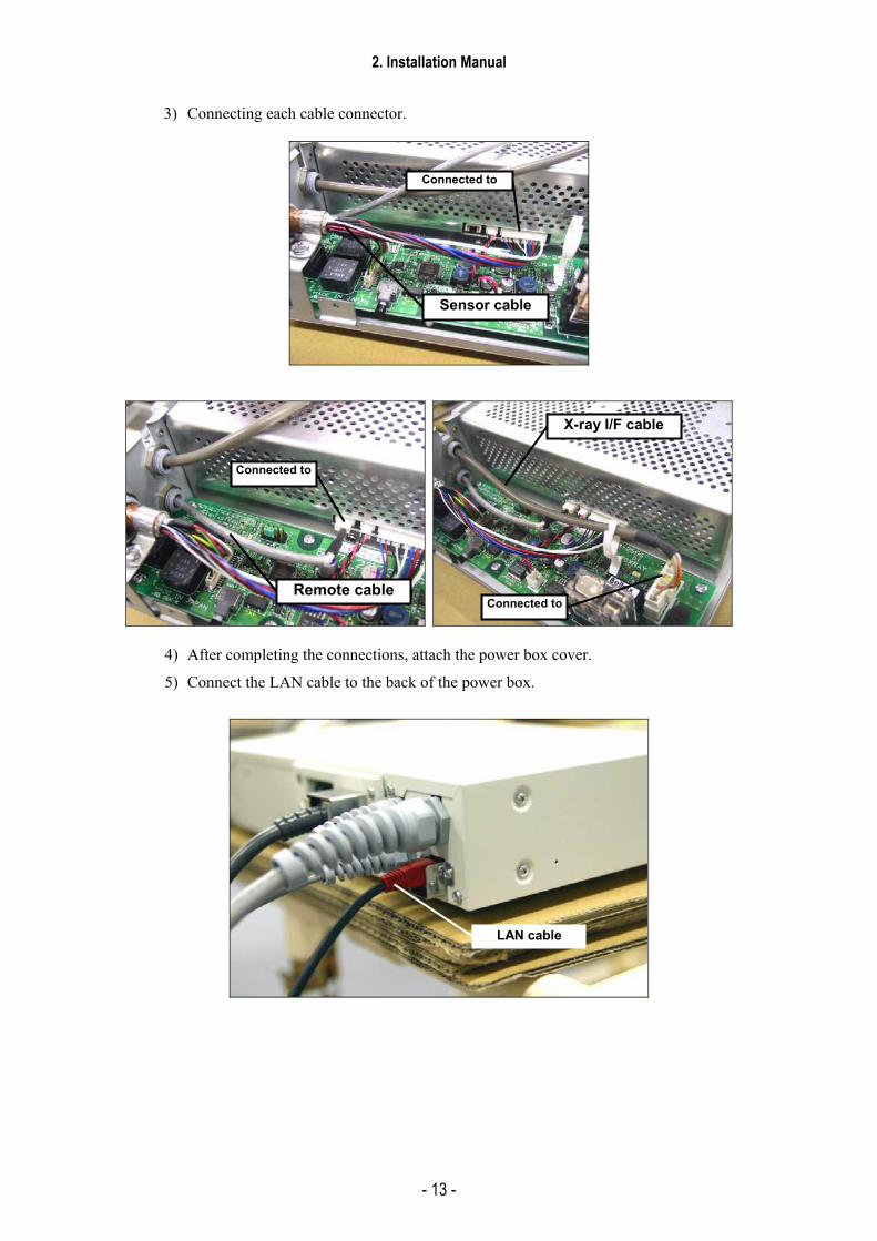
(3) Cable connections 1) Loosen the lock nut for each cable and connect the cables to the power box. Then fix
the cables by tightening the lock nuts.
Note: To avoid the risk of damage when the cables are removed with very large force, Check tightening torque of the bush (refer the following figure).
<Sensor cable> <X-RAY I/F cable,
Remote cable>
2) Attach the cable clamp to the sensor cable, and then fix it to the power box using the screw (M4 x 6 mm).
Lock nut
X-ray I/F cable
Sensor cable
Remote cable
Cable clamp
Screw (M4×6mm)
Clamp the cable’s shield portion
Gap 1.0 to 1.5mmNo gap
2. Installation Manual
- 13 -
3) Connecting each cable connector.
4) After completing the connections, attach the power box cover.
5) Connect the LAN cable to the back of the power box.
Sensor cable
Connected to
Remote cable
Connected to
X-ray I/F cable
Connected to
LAN cable

2. Installation Manual
- 14 -
6) Connect the power cable to the back of the power box.
CXDI-50G/50C sensor cable
Remote cable
X-ray I/F cable
Power cable
Power switch
LAN cable
Power cable
2. Installation Manual
- 15 -
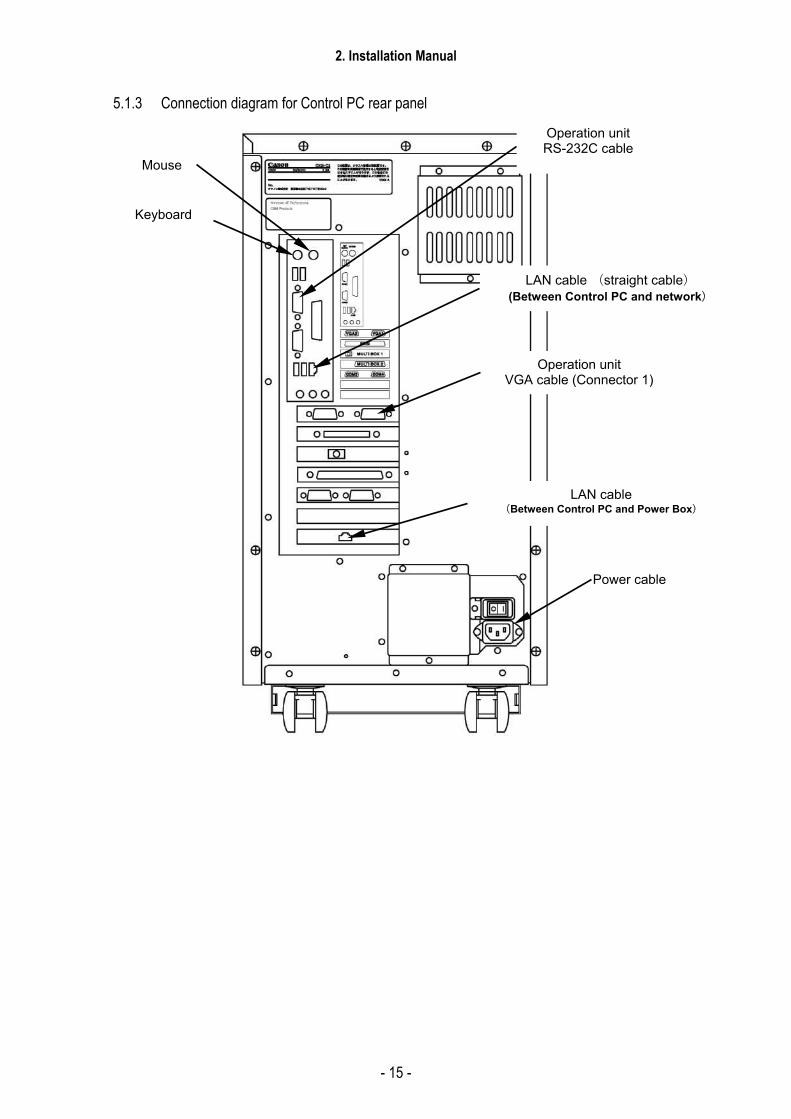
5.1.3 Connection diagram for Control PC rear panel
LAN cable (Between Control PC and Power Box)
Mouse
Keyboard
Operation unit RS-232C cable
Operation unit VGA cable (Connector 1)
LAN cable (straight cable) (Between Control PC and network)
Power cable
2. Installation Manual
- 16 -
5.2 Starting up and shutting down the System Perform the following sequences when starting up and shutting down the system.
5.2.1 Sequence for Starting up the System Perform the following sequence when turning the system power on.
If you do not perform the correct sequence, the imaging unit cannot be recognized, resulting in an error. (This is because the system communicates with the imaging unit when turning the system on.)
The power box cannot be turned on in conjunction with turning on the control PC.
Since the power box is equipped with a remote switch that turns on/off the secondary output, you can install the switch on your side to turn it on/off.
1) Turn on the main power of the power box.
2) Turn on the remote switch of the power box.
3) Turn on the control PC.
Note:
Ccrstart.bat should be registered in Windows Startup.
5.2.2 Sequence for Turning the Power off (Shutdown) 1) From OPU, select SYSTEM → [SHUTDOWN] or [SHUTDOWN after transfer]
The control PC automatically turns off.
2) Turn off the remote switch of the power box.
3) Turn off the main power of the power box.
Note:
Turn off the main power of the power box and OPU power when not using the system for a long period.
2. Installation Manual
- 17 -
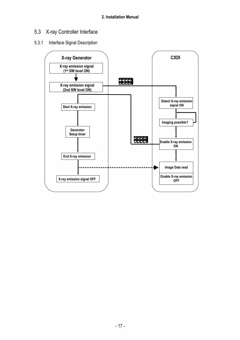
5.3 X-ray Controller Interface
5.3.1 Interface Signal Description
Start X-ray emission
End X-ray emission
X-ray emission signal OFF
Detect X-ray emissionsignal ON
Imaging possible?
Enable X-ray emission ON
X-ray Generator CXDI
Image Data read
RX_REQ
Generator Setup timer
X-ray emission signal (1st SW level ON)
X-ray emission signal (2nd SW level ON)
RX_COM
Enable X-ray emission OFF
2. Installation Manual
- 18 -
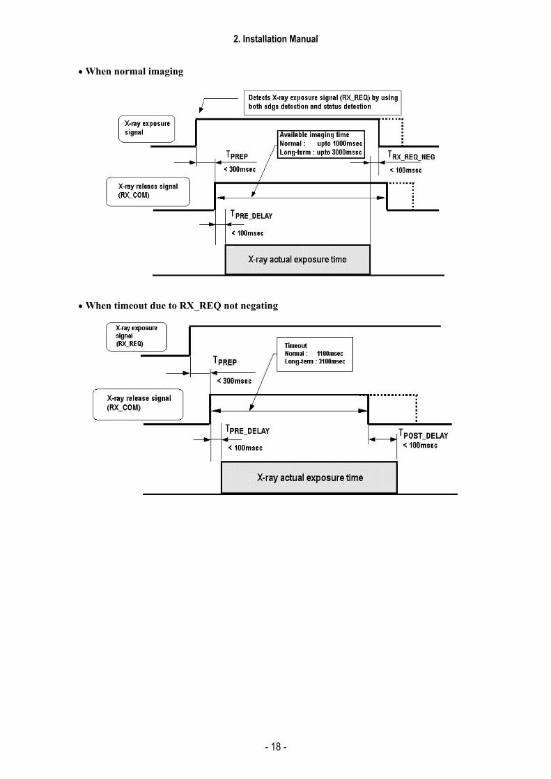
• When normal imaging
• When timeout due to RX_REQ not negating

2. Installation Manual
- 19 -
5.3.2 Signal names and functions in the connection with the X-ray generator <X-ray Sync Signal>
Signal name Functions
RX_REQ
X-ray exposure signal Indicates that an X-ray exposure is ordered at the X-ray generator side. This signal needs to be retained at least for TPREP period. X-ray release signal (RX_COM) is not output if the TPREP is less than the necessary period. It takes about 1 second in the worst case scenario before the operation can be resumed when RX_REQ is negated in this period. Time required to assert RX_COM after receiving the RX_REQ from the X-ray generator TPREP....................................................................... min.300 ms Since a captured image is read from the sensor when RX_REQ is negated (or RX_COM is time out) as a trigger, reading action is delayed if RX_COM does not negate and time out is used as the trigger, resulting in delay of image display timing. We recommend using a configuration in which RX_REQ is negated. Time required from X-ray exposure completion to negating RX_REQ TRX_REQ_NEG ............................................................min.0 max.100ms * Image display timing is delayed if this is not fulfilled.
RX_COM
X-ray release signal Checks whether or not imaging is ready at the CXDI side after receiving X-ray exposure signal (RX_REQ) from the X-ray generator. This signal is output to the X-ray generator side when imaging is ready. Time required from asserting RX_COM to exposing X-ray TPRE_DELAY ..............................................................min.0 max.100ms * Available imaging time is reduced if this is not fulfilled. Time required to stop X-ray exposure after RX_COM halts TPOST_DELAY ............................................................min.0 max.100ms * Shading could occur on images if this is not fulfilled.
2. Installation Manual
- 20 -
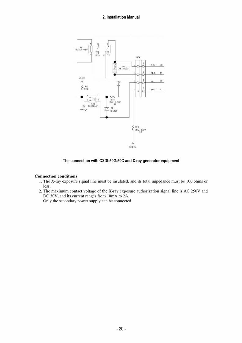
The connection with CXDI-50G/50C and X-ray generator equipment Connection conditions
1. The X-ray exposure signal line must be insulated, and its total impedance must be 100 ohms or less.
2. The maximum contact voltage of the X-ray exposure authorization signal line is AC 250V and DC 30V, and its current ranges from 10mA to 2A. Only the secondary power supply can be connected.

2. Installation Manual
- 21 -
5.3.3 Rating and Characteristics for Relay and Photo coupler (on PWB-40XRAY Board) (1) RL1 (Power Relay/Plug-in terminal type)
1) Rating (Operational coil)
Rated curre
nt
Coil resistance
Coil Inductance (mH)
Pick-up voltage
Dropout voltage
Maximum voltage
Power consumptionRated
voltage (V)
(mA) (Ω) Armature OFF
Armature ON (V) (V) (V) (mW)
DC5V 72 69.4 69.5 86.0 below 80%
below 10%
135% (at 50) Approx 360
2) Rating (Switch/Contact)
types Single stable arrangement 2 Form C Contact material Au-clad AgNi type
Relating capacity AC250 5A DC30V 5A
Max. switching power 1250VA 150W Max. switching voltage 250V AC Max. switching current 5A Min. switching capacity 100µA 1V DC
3) Characteristics
Item Content Operate time Max. 20ms Reset time Max. 10ms
Mechanical 18,000 times/hour Maximum open/close frequency Rated load 1,800 times/hour
Between coil contacts 2,000 Vrms Withstand voltage Between same poles 1,000 Vrms Mechanical 5x10⁷ times
life Electrical 105 at 5A 250V AC 5x10⁵ at 5A 30V DC
Ambient temperature -40°C to +70°C (no freezing nor condensation) Maximum operating frequency 50 times/Sec.
2. Installation Manual
- 22 -
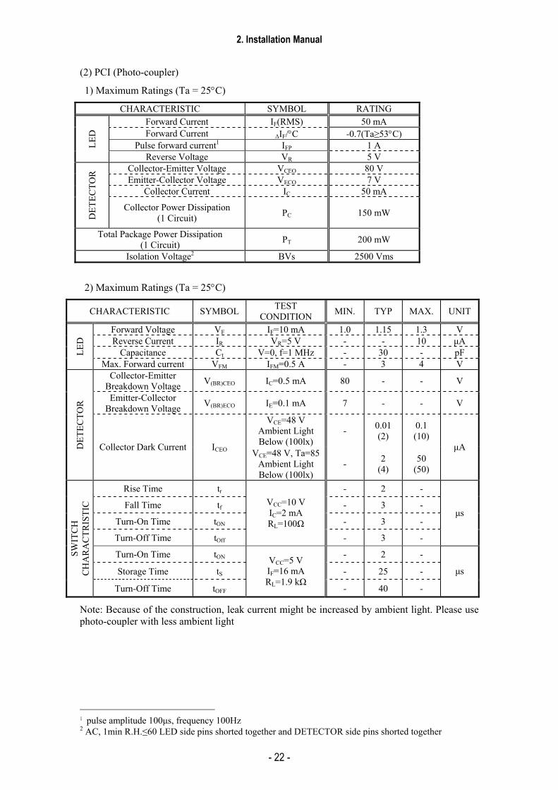
(2) PCI (Photo-coupler)
1) Maximum Ratings (Ta = 25°C)
CHARACTERISTIC SYMBOL RATING Forward Current IF(RMS) 50 mA Forward Current ∆IF/°C -0.7(Ta≥53°C)
Pulse forward current1 IFP 1 A LED
Reverse Voltage VR 5 V Collector-Emitter Voltage VCEO 80 V Emitter-Collector Voltage VECO 7 V
Collector Current IC 50 mA
DET
ECTO
R
Collector Power Dissipation (1 Circuit) PC 150 mW
Total Package Power Dissipation (1 Circuit) PT 200 mW
Isolation Voltage2 BVs 2500 Vms
2) Maximum Ratings (Ta = 25°C)
CHARACTERISTIC SYMBOL TEST CONDITION MIN. TYP MAX. UNIT
Forward Voltage VF IF=10 mA 1.0 1.15 1.3 V Reverse Current IR VR=5 V - - 10 µA
Capacitance Ct V=0, f=1 MHz - 30 - pF LED
Max. Forward current VFM IFM=0.5 A - 3 4 V Collector-Emitter
Breakdown Voltage V(BR)CEO IC=0.5 mA 80 - - V
Emitter-Collector Breakdown Voltage V(BR)ECO IE=0.1 mA 7 - - V
VCE=48 V Ambient Light Below (100lx)
- 0.01 (2)
0.1 (10)
DET
ECTO
R
Collector Dark Current ICEO VCE=48 V, Ta=85 Ambient Light Below (100lx)
- 2 (4)
50 (50)
µA
Rise Time tr - 2 -
Fall Time tf - 3 -
Turn-On Time tON - 3 -
Turn-Off Time tOff
VCC=10 V IC=2 mA RL=100Ω
- 3 -
µs
Turn-On Time tON - 2 -
Storage Time tS - 25 -
SWIT
CH
C
HA
RA
CTR
ISTI
C
Turn-Off Time tOFF
VCC=5 V IF=16 mA RL=1.9 kΩ
- 40 -
µs
Note: Because of the construction, leak current might be increased by ambient light. Please use photo-coupler with less ambient light
1 pulse amplitude 100µs, frequency 100Hz 2 AC, 1min R.H.≤60 LED side pins shorted together and DETECTOR side pins shorted together
2. Installation Manual
- 23 -
5.4 Network Settings 1 1. Objective
The CXDI-50G/50C imaging part communicates with the control PC by using Ethernet [IEEE802.3u (100Base-TX)] to transfer X-ray images.
The control PC performs DICOM transfer in order to use Ethernet to transfer the obtained images to the printer and storage device.
This section describes how to set up the TCP/IP that is necessary for the network connection.
Set up the following three items:
1) TCP/IP setting for the control PC network card
2) Network setting for Screwcap.ini
3) Network setting stored in the CXDI-50G/50C sensor
2. Preparation
• Keyboard • Mouse
Connect the keyboard and mouse to the back of the control PC.
Check if the system is connected, and then turn the system on.
3. Setup method
3.1 TCP/IP setting for the control PC network card
Perform the set up by referring to “C3S Service Manual” -> the chapter “System Manual” -> “Network Setup”.
Default values
IP Address:192.168.100.10
SubnetMask:255.255.255.0
2. Installation Manual
- 24 -
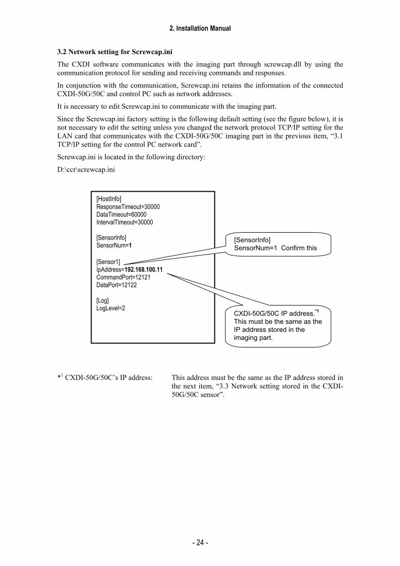
3.2 Network setting for Screwcap.ini
The CXDI software communicates with the imaging part through screwcap.dll by using the communication protocol for sending and receiving commands and responses.
In conjunction with the communication, Screwcap.ini retains the information of the connected CXDI-50G/50C and control PC such as network addresses.
It is necessary to edit Screwcap.ini to communicate with the imaging part.
Since the Screwcap.ini factory setting is the following default setting (see the figure below), it is not necessary to edit the setting unless you changed the network protocol TCP/IP setting for the LAN card that communicates with the CXDI-50G/50C imaging part in the previous item, “3.1 TCP/IP setting for the control PC network card”.
Screwcap.ini is located in the following directory:
D:\ccr\screwcap.ini
*1 CXDI-50G/50C’s IP address: This address must be the same as the IP address stored in
the next item, “3.3 Network setting stored in the CXDI-50G/50C sensor”.
[HostInfo] ResponseTimeout=30000 DataTimeout=60000 IntervalTimeout=30000 [SensorInfo] SensorNum=1 [Sensor1] IpAddress=192.168.100.11 CommandPort=12121 DataPort=12122 [Log] LogLevel=2
[SensorInfo] SensorNum=1 Confirm this
CXDI-50G/50C IP address.*1 This must be the same as the IP address stored in the imaging part.

2. Installation Manual
- 25 -
3.3 Network setting stored in the CXDI-50G/50C sensor
The factory default setting is shown in the table below.
This setting is not necessary unless you have changed the setting.
Item to be set Factory default value Sensor IP address 192.168.100.11 Subnet mask 255.255.255.0 Host IP address 192.168.100.10 Port number for command 12121 Port number for data 12122 If you change the setting, refer to “Tool Software Operation Manual for Ethernet” → “Imaging Part IP Address Setting”.

2. Installation Manual
- 26 -
5.5 Setting the Fixed ROI Areas 1) Purpose
Set the fixed ROI area on the sensor to expose by the fixed ROI area because user can not get the proper image by the Auto ROI area.
2) Setting method
2-1) Investigate the actual size and position of the ROI that is required.
2-2) Designate the SIZE, POSITION, and NUMBER (max 5)* on the sensor. * However, in the case of using the new function “Display of AEC (Automated Exposure Control)
Field in Preview Screen” added from CXDI System Software Ver.6.2, NUMBER that can be specified is max 3.
Ws=350mm
Hs=430m
m
(0,0)
W
H
Sensor
X
Y
2-3) Convert the size and position of the ROIs in 2) to pixel values. The pixel size of the sensor is 160µm. For multiple values, use X’, Y’, W’, H’, X”, Y”, W”, and H” for calculations.
X/160 µm Let this value equal A Y/160 µm Let this value equal B W/160 µm Let this value equal C H/160 µm Let this value equal D
2-4) Open the “DENSITY ADJUSTMENT CONTROL” screen when the normal imaging screen is active.
SYSTEM SETUP MENU SYSTEM SETTINGS DENSITY ADJUSTMENT CONTROL
2. Installation Manual
- 27 -
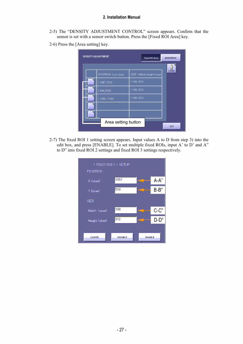
2-5) The “DENSITY ADJUSTMENT CONTROL” screen appears. Confirm that the sensor is set with a sensor switch button. Press the [Fixed ROI Area] key.
2-6) Press the [Area setting] key.
2-7) The fixed ROI 1 setting screen appears. Input values A to D from step 3) into the edit box, and press [ENABLE]. To set multiple fixed ROIs, input A’ to D’ and A” to D” into fixed ROI 2 settings and fixed ROI 3 settings respectively.
Area setting button
2. Installation Manual
- 28 -
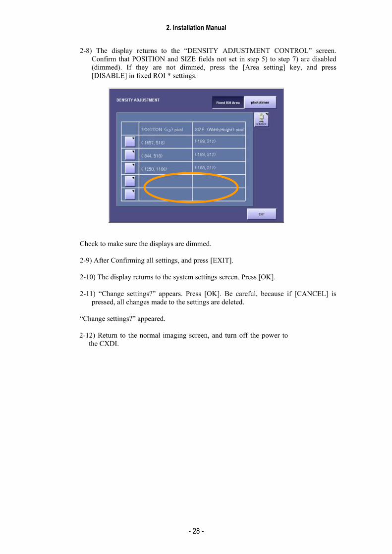
2-8) The display returns to the “DENSITY ADJUSTMENT CONTROL” screen. Confirm that POSITION and SIZE fields not set in step 5) to step 7) are disabled (dimmed). If they are not dimmed, press the [Area setting] key, and press [DISABLE] in fixed ROI * settings.
Check to make sure the displays are dimmed.
2-9) After Confirming all settings, and press [EXIT].
2-10) The display returns to the system settings screen. Press [OK].
2-11) “Change settings?” appears. Press [OK]. Be careful, because if [CANCEL] is pressed, all changes made to the settings are deleted.
“Change settings?” appeared.
2-12) Return to the normal imaging screen, and turn off the power to
the CXDI.

2. Installation Manual
- 29 -
5.6 Adjusting the photo timer
<Outline> The photo timer installed in the imaging unit is adjusted so that the exposure time of the X-rays generated by the X-ray generators is to OFF using the optimal value. * This work necessitates performing some adjustments inside the X-ray generators. In order to
ensure that the work will proceed smoothly, discuss the schedule and other details with the representative of the manufacturer of the X-ray generators.
<Preparations> (1) Start up the CXDI system. (Normal radiography mode) (2) Perform calibration. (3) Change parameters of VPT button as follows.
* This operation must be done by the “VPT” button which uses “fixed ROI”. The adjustment cannot be performed properly by the body parts buttons which use auto ROI.
1) From SYSTEM > EDIT EXPOSURE MODE, select VPT button. 2) Press the NEXT PAGE button to enter the parameter editing screen and then set the following
parameters. (A) GENERATOR PARAMETER SCREEN
Set only the center of the fixed ROI area to ON. (During the adjustment, the acrylic sheet may be used to cover the fixed ROI area selected here.)
(B) IP PARAMETER SCREEN
CURVE SHAPE: CHEST BRIGHTNESS: 6 CONTRAST: 10
[GENERATOR PARAMETER SCREEN] [IP PARAMETER SCREEN]
3) Press the OK button to save the parameters you changed.
Turn on this area only
CHEST
BRIGHTNESS: 6
CONTRAST: 10
2. Installation Manual
- 30 -
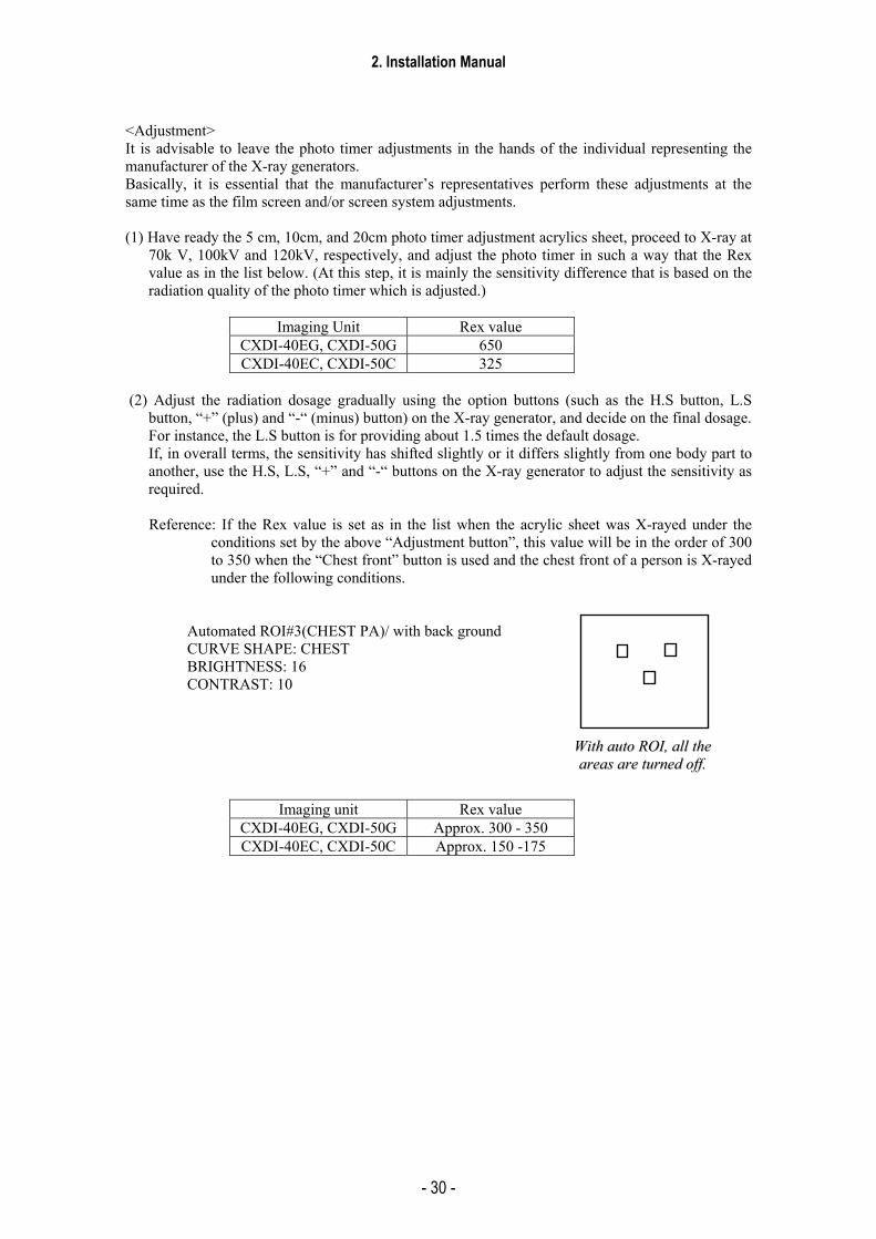
<Adjustment> It is advisable to leave the photo timer adjustments in the hands of the individual representing the manufacturer of the X-ray generators. Basically, it is essential that the manufacturer’s representatives perform these adjustments at the same time as the film screen and/or screen system adjustments. (1) Have ready the 5 cm, 10cm, and 20cm photo timer adjustment acrylics sheet, proceed to X-ray at
70k V, 100kV and 120kV, respectively, and adjust the photo timer in such a way that the Rex value as in the list below. (At this step, it is mainly the sensitivity difference that is based on the radiation quality of the photo timer which is adjusted.)
Imaging Unit Rex value
CXDI-40EG, CXDI-50G 650 CXDI-40EC, CXDI-50C 325
(2) Adjust the radiation dosage gradually using the option buttons (such as the H.S button, L.S
button, “+” (plus) and “-“ (minus) button) on the X-ray generator, and decide on the final dosage. For instance, the L.S button is for providing about 1.5 times the default dosage. If, in overall terms, the sensitivity has shifted slightly or it differs slightly from one body part to another, use the H.S, L.S, “+” and “-“ buttons on the X-ray generator to adjust the sensitivity as required.
Reference: If the Rex value is set as in the list when the acrylic sheet was X-rayed under the
conditions set by the above “Adjustment button”, this value will be in the order of 300 to 350 when the “Chest front” button is used and the chest front of a person is X-rayed under the following conditions.
Automated ROI#3(CHEST PA)/ with back ground CURVE SHAPE: CHEST BRIGHTNESS: 16 CONTRAST: 10
Imaging unit Rex value CXDI-40EG, CXDI-50G Approx. 300 - 350 CXDI-40EC, CXDI-50C Approx. 150 -175
WWiitthh aauuttoo RROOII,, aallll tthhee aarreeaass aarree ttuurrnneedd ooffff..

2. Installation Manual
- 31 -
5.7 Settings (1) Checking and Setting the Date and Time
Description about CCR application in ‘Setting’ may change to some degree depending on the versions of application. For CCR application, see “New Function Descriptions” issued for every version if necessary.
1) Purpose
The date and time is set to Japan standard time at factory shipment.
Reset the date and time to your local value as necessary.
2) Procedure
2-1) When CXDI application start, open the ADMINISTRATOR SETUP MENU.
SYSTEM → SETUP MENU → ADMINISTRATOR SETUP
2-2) When the “ADMINISTRATOR SETUP MENU” appears, and presses the [DATE] button.
2-3) The dialog (Date / Time Properties) appears, and set the value properly each of the fields which the tab sheet (Date&Time and Time Zone sheet) has. And then press [OK].
2. Installation Manual
- 32 -
(2) Checking the Firmware Version
1) Purpose
1-1) Failing to use the proper versions of the firmware and PLD code with the CXDI application can result in an error, and system operation cannot be guaranteed. Therefore, the versions of the firmware must be checked to ensure that they are correct. (The combination of this firmware refers to CXDI Software Combination List.)
2) Notes
2-1) This check should always be performed at installation, and if necessary, the firmware versions should be upgraded.
2-2) This check cannot be performed with only the control PC. Connect the imaging units and other equipment, and start up in the normal imaging status.
3) Procedure
3-1) Checking the firmware alone
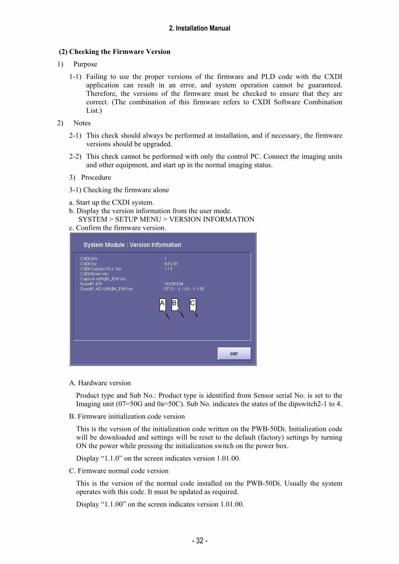
a. Start up the CXDI system. b. Display the version information from the user mode. SYSTEM > SETUP MENU > VERSION INFORMATION c. Confirm the firmware version.
A. Hardware version
Product type and Sub No.: Product type is identified from Sensor serial No. is set to the Imaging unit (07=50G and 0a=50C). Sub No. indicates the states of the dipswitch2-1 to 4.
B. Firmware initialization code version
This is the version of the initialization code written on the PWB-50Di. Initialization code will be downloaded and settings will be reset to the default (factory) settings by turning ON the power while pressing the initialization switch on the power box.
Display “1.1.0” on the screen indicates version 1.01.00.
C. Firmware normal code version
This is the version of the normal code installed on the PWB-50Di. Usually the system operates with this code. It must be updated as required.
Display “1.1.00” on the screen indicates version 1.01.00.
A B C

2. Installation Manual
- 33 -
3-2) Checking the firmware and PLD code
(1) Connect the keyboard and mouse.
(2) Start up the CXDI system.
(3) Close the CXDI host software if it starts up.
(4) Connect Telnet by referring to “Telnet Connection” in the Tool Software Operation Manual for Ethernet.
(5) Check the versions of the firmware and PLD code on the screen displayed after the login.
(6) After you finish checking, close HyperTerminal.
login: canon
Password: ********
CXDI-50G firmware Ver.1.01.00
build as Jul 2 2003 16:13:45
normal boot
HUB50 Ver.5010 product code:0701
pcb-50di>
Firmware version
Hardware version
PLD code version

2. Installation Manual
- 34 -
(3) Installing Firmware and PLD Code
1) Purpose
Write exposure code and PLD code into the Flash ROM of the PWB-50Di in the imaging unit.
2) Notes
Be sure to check that the CXDI is connected to the system.
3) Procedure
3-1) Installing the firmware
Write the firmware by referring to “Firm Write Tool Software (Firmwrite.exe)” in the Tool Software Operation Manual for Ethernet.
Where to write: IC1 (Flash ROM) on PWB-50Di
3-2) Installing PLD code
Write PLD code by referring to “PLD Write Tool Software (pldwrite.exe)” in the Tool Software Operation Manual for Ethernet.
Where to write: IC11 (PLD) on PWB-50Di.

2. Installation Manual
- 35 -
(4) Checking the Sensor Serial No.
1) Purpose
If the sensor serial number and the sensor serial number stored in the flash ROM of the PWB-50Di differ from the image data file name stored in the hard drive of the Control PC due to replacing the PWB-50Di or imaging unit, the connected sensor can not be detected after the CXDI application is launched. In that case an error message appears.
2) Notes
2-1) Check the sensor serial No. whenever:
a. PWB-50Di is replaced.
b. Sensor in the imaging unit is replaced.
2-2) This checking procedure must be performed with the Control PC, Imaging Unit and all the other equipments connected and started up.
3) Procedure
3-1) Check the sensor serial No. by referring to “Sensor serial number setting” in the Tool Software Operation Manual for Ethernet, and write the number as required.

2. Installation Manual
- 36 -
(5) Set Up Startup Menu
1) Purposes
1-1) Register the CXDI application software to the “Startup Group”.
The CXDI application software is scheduled to start automatically at the CXDI system starting
1-2) Change the window view size
Hide the other application screen view except the CXDI application software.
1-3) Delete the CXDI application software from the “Startup Group”.
The CXDX application software is not started at the CXDI system starting.
2) Notes
2-1) The CXDI application software is not registered in the “Startup Group” at the factory setting.
Therefore register the CXDI application software to the “Startup Group” after the system installation.
2-2) The window view size of the program registered in “Startup Group” has one own size with the each short-cut icon. Be sure to set the window view size of CXDI application software at the same time with the register to the “Startup Group”.
3) Register the CXDI application software to the “Startup Group” procedure.
3-1) Connect keyboard and mouse to the control PC.
3-2) Turns the all CXDI system power on after the all installation finished. And after that Windows XP starts.
3-3) Open the “Taskbar and Start Menu” from the Start Menu.
Start⇒Settings⇒Taskbar and Start Menu
3-4) “Taskbar and Start Menu Properties” appears. Click “Start Menu” tab, and then click
Taskbar and Start Menu Properties⇒Start Menu⇒Classic Start⇒Menu Customize
3-5) Click Add, and Create Shortcut appears. Click Browse.
3-6) Browse appears. Find a file named “ccrstart.bat” in drive [D:\ccr] and click OK.
3-7) D:\ccr\ccrstart.bat appears in the Command line. Click Next.
3-8) Select Program Folder appears. Select Startup folder and click [Next].
3-9) Select a name for the shortcut appears. Type ccrstart.bat. Click [Finish].
3-10) Close the Taskbar [Start], and login again to Windows XP.
Start⇒Shut Down⇒Log off cxdi.
3-11) After login the computer, make sure that the CXDI application starts up.
2. Installation Manual
- 37 -
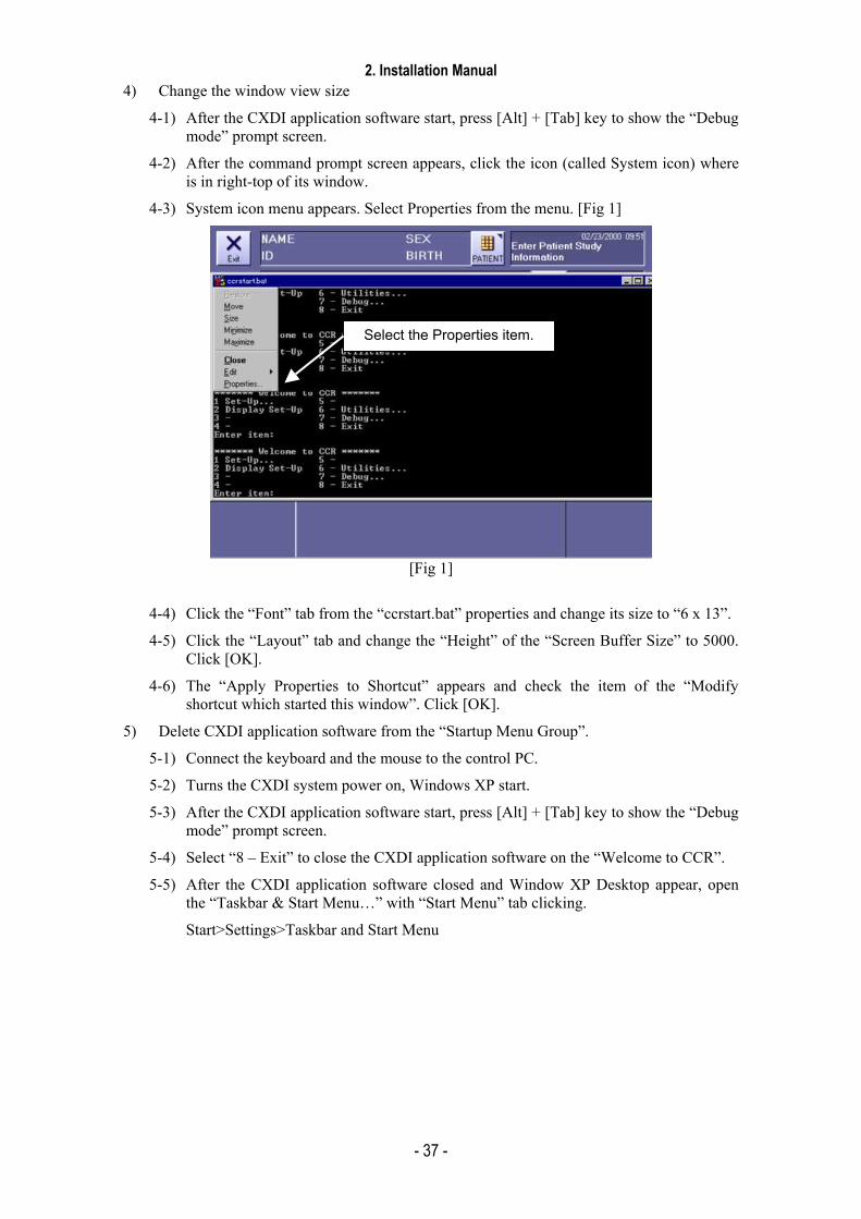
4) Change the window view size
4-1) After the CXDI application software start, press [Alt] + [Tab] key to show the “Debug mode” prompt screen.
4-2) After the command prompt screen appears, click the icon (called System icon) where is in right-top of its window.
4-3) System icon menu appears. Select Properties from the menu. [Fig 1]
[Fig 1]
4-4) Click the “Font” tab from the “ccrstart.bat” properties and change its size to “6 x 13”.
4-5) Click the “Layout” tab and change the “Height” of the “Screen Buffer Size” to 5000. Click [OK].
4-6) The “Apply Properties to Shortcut” appears and check the item of the “Modify shortcut which started this window”. Click [OK].
5) Delete CXDI application software from the “Startup Menu Group”.
5-1) Connect the keyboard and the mouse to the control PC.
5-2) Turns the CXDI system power on, Windows XP start.
5-3) After the CXDI application software start, press [Alt] + [Tab] key to show the “Debug mode” prompt screen.
5-4) Select “8 – Exit” to close the CXDI application software on the “Welcome to CCR”.
5-5) After the CXDI application software closed and Window XP Desktop appear, open the “Taskbar & Start Menu…” with “Start Menu” tab clicking.
Start>Settings>Taskbar and Start Menu
Select the Properties item.
2. Installation Manual
- 38 -
5-6) “Taskbar and Start Menu Properties” appears. Click “Start Menu” tab, and then click Taskbar and Start Menu Properties⇒Start Menu⇒Classic Start⇒Menu Customize
5-7) The “Remove Shortcuts/Folders” dialog box appears after click the “Remove” button. And double-click the “Startup folder”
5-8) Remove the “ccrstart.bat” item from it.
5-9) After “Remove” button clicked, the confirmation of deleting file appears. If you are going to remove it, click “Yes” button.
5-10) After confirm that the “ccrstart.bat” item is removed from “Startup Group”, close all the application on the desktop and re-login to Windows XP.
5-11) Make sure that the CXDI application software will not start automatically after login to Windows XP. And then shutdown Windows XP, turn the CXDI system power off.
* When the CXDI application is deleted from the Start menu due to repair or other reasons, be sure to always perform the procedures outlined in “Adding CXDI application software onto the Start menu” and “Changing the window size” when the repair is complete.
2. Installation Manual
- 39 -
(6) Identifying the Sensor Units
1) Purpose
In order for the control PC to identify the sensor units connected, the sensor serial number of each sensor unit is input to the Control PC.
2) Notes
2-1) These operations must always be implemented at the installation stage and when any of the Imaging Units (sensor) or Control PC (hard disk) has been replaced or when the combination of equipment has been changed.
2-2) The sensor serial numbers must always be input. If the serial numbers of the sensor unit and Control PC do not match, “Sensor Unit: Detect Error (-5100)” will be displayed on starting up the system. These numbers are the same as what is input to the PWB-50Di. (Refer to “ Checking the sensor serial numbers”.)
3) Preparations (What to have ready)
Tool keyboard, tool mouse
4) Procedure
4-1) Start up the CXDI unit.
4-2) Once the normal sensor screen has appeared on the operation unit, use the keyboard to enter the debugging mode (Use [ALT] + [TAB].).
4-3) “Welcome to CCR” appears. Select “1 Set-Up...”
4-4) “Setting Mode (0:Normal, 1:Expert)[0=0x0]:” appears. Select “0:Normal.”
4-5) “CCR SETUP MENU” appears. Select “7 Scan Sensor Setup.”
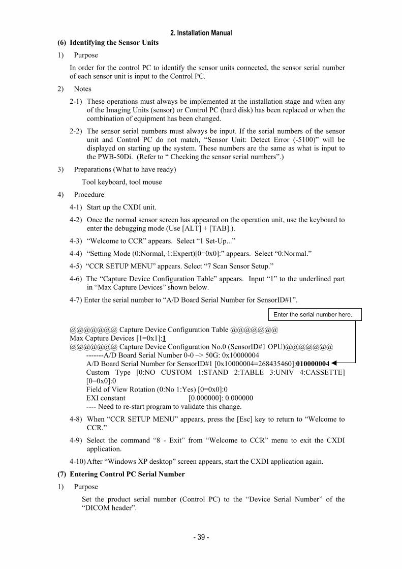
4-6) The “Capture Device Configuration Table” appears. Input “1” to the underlined part in “Max Capture Devices” shown below.
4-7) Enter the serial number to “A/D Board Serial Number for SensorID#1”.
@@@@@@@ Capture Device Configuration Table @@@@@@@ Max Capture Devices [1=0x1]:1 @@@@@@@ Capture Device Configuration No.0 (SensorID#1 OPU)@@@@@@@
-------A/D Board Serial Number 0-0 –> 50G: 0x10000004 A/D Board Serial Number for SensorID#1 [0x10000004=268435460]:010000004 Custom Type [0:NO CUSTOM 1:STAND 2:TABLE 3:UNIV 4:CASSETTE] [0=0x0]:0 Field of View Rotation (0:No 1:Yes) [0=0x0]:0 EXI constant [0.000000]: 0.000000 ---- Need to re-start program to validate this change.
4-8) When “CCR SETUP MENU” appears, press the [Esc] key to return to “Welcome to CCR.”
4-9) Select the command “8 - Exit” from “Welcome to CCR” menu to exit the CXDI application.
4-10) After “Windows XP desktop” screen appears, start the CXDI application again.
(7) Entering Control PC Serial Number
1) Purpose
Set the product serial number (Control PC) to the “Device Serial Number” of the “DICOM header”.
Enter the serial number here.
2. Installation Manual
- 40 -
2) Procedure
2-1) Start up the CXDI system.
2-2) After the exposure screen appears on the operation unit, use the keyboard to enter Debug mode. (Use [Alt] + [Tab].)
2-3) “Welcome to CCR” screen appears. Select the command “1. Set-Up…”
2-4) The “Setting Mode (0: Normal, 1: Expert) [0=0×0]:” is prompted. Select “0: Normal”
2-5) “CCR SETUP MENU” appears. Select the command ”1. System Setup”.
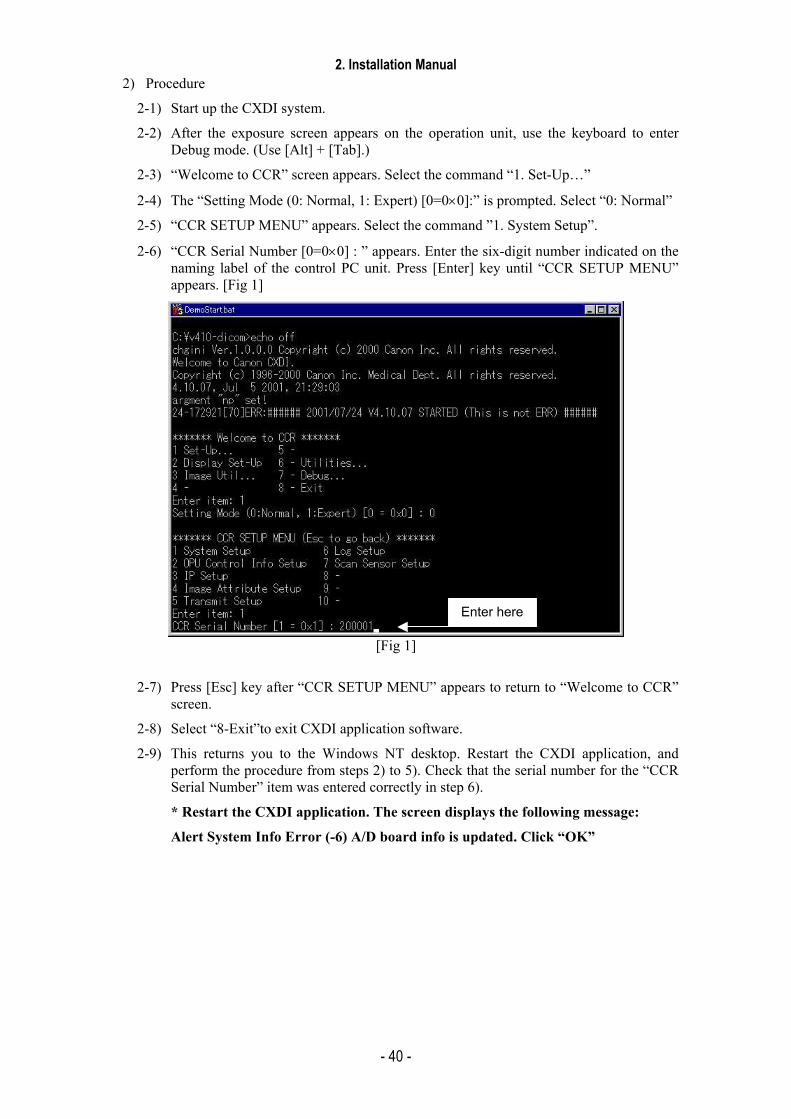
2-6) “CCR Serial Number [0=0×0] : ” appears. Enter the six-digit number indicated on the naming label of the control PC unit. Press [Enter] key until “CCR SETUP MENU” appears. [Fig 1]
[Fig 1]
2-7) Press [Esc] key after “CCR SETUP MENU” appears to return to “Welcome to CCR” screen.
2-8) Select “8-Exit”to exit CXDI application software.
2-9) This returns you to the Windows NT desktop. Restart the CXDI application, and perform the procedure from steps 2) to 5). Check that the serial number for the “CCR Serial Number” item was entered correctly in step 6).
* Restart the CXDI application. The screen displays the following message:
Alert System Info Error (-6) A/D board info is updated. Click “OK”
Enter here
2. Installation Manual
- 41 -
(8) Table Setup Settings
1) Purpose
Adjust the CXDI operation unit's TABLE SETUP to match the exposure conditions (X-ray tube voltage, X-ray tube current, msec or mAs value) of the X-ray generator.
2) Procedure
2-1) Start the CXDI system.
2-2) Open the TABLE SETUP Change window from the Normal Exposure window.
System ⇒ SETUP MENU ⇒ SYS. SETUP ⇒ TABLE SETUP
2-3) Select the tabs to be changed and change the X-ray tube voltage, X-ray tube current, and msec value data to match the exposure conditions of the X-ray generator.
* See the operation manual for the details of settings.
2-4) After finishing the changes, return to the Normal Exposure window and check that the TABLE SETUP has been changed.

2. Installation Manual
- 42 -
(9) Performing the Annotation Settings
1) Purpose
The settings for imprinting the annotation onto the film and the settings of the characters used for the annotation are performed.
2) Procedure
2-1) Once the normal radiographic screen has started, open the annotation setting screen.
SYSTEM → SETUP MENU → SYS. SETUP → ANNOTATION
2-2) The annotation setting screen now appears. Proceed with the settings that will make it possible to put the data desired by the user.
* See the operation manual for the details of settings.

2. Installation Manual
- 43 -
(10) Network Connections
Network settings
1) Purpose These settings are for connecting the CXDI to the network.
1-1) Set the CXDI’s IP address, subnet mask and default gateway in Windows XP.
1-2) Set the printer and storage output destinations and parameters on the user screen.
2) Checkpoints
2-1) This item involves checking the details of the checks performed on network setting parameters among the pre-installation inspection details and setting these parameters.
* Refer to “Appendix: Investigation Report” for the pre-installation investigation details.
2-2) Perform the settings of this item carefully since any errors made in these settings will make it impossible for connection to be made to the network or the images to be transmitted properly, etc.
3) Windows XP settings
3-1) Connect the keyboard and mouse to the control PC.
3-2) After turning on the Operation unit’s power and then the Control PC’s power, start Windows XP.
3-3) The Windows XP desktop screen appears. Right-click the [My Network] icon, and select My Network Places from the menu.
3-4) When [Network Connection] appears, double click on Local Area Connection (Intel(R) PRO/100VE Network Connection).
3-5) When Local Area Connection Properties appears, click on the General tab, select [Internet Protocol (TCP/IP)], and click Properties.
3-6) Based on the pre-install of inspection details set the IP address, subnet mask and default gateway.
[Fig 1]
2. Installation Manual
- 44 -
3-7) Upon completion of the setting, restart the Windows XP.
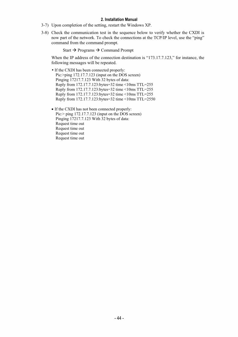
3-8) Check the communication test in the sequence below to verify whether the CXDI is now part of the network. To check the connections at the TCP/IP level, use the “ping” command from the command prompt.
Start Programs Command Prompt
When the IP address of the connection destination is “173.17.7.123,” for instance, the following messages will be repeated.
If the CXDI has been connected properly: Pic:>ping 172.17.7.123 (input on the DOS screen) Pinging 17217.7.123 With 32 bytes of data: Reply from 172.17.7.123:bytes=32 time <10ms TTL=255 Reply from 172.17.7.123:bytes=32 time <10ms TTL=255 Reply from 172.17.7.123:bytes=32 time <10ms TTL=255 Reply from 172.17.7.123:bytes=32 time <10ms TTL=2550
• If the CXDI has not been connected properly:
Pic:> ping 172.17.7.123 (input on the DOS screen) Pinging 17217.7.123 With 32 bytes of data: Request time out Request time out Request time out Request time out
2. Installation Manual
- 45 -
4) Set the printer and storage device which serves as the external output destinations. In this case, one printer and one storage device are set.
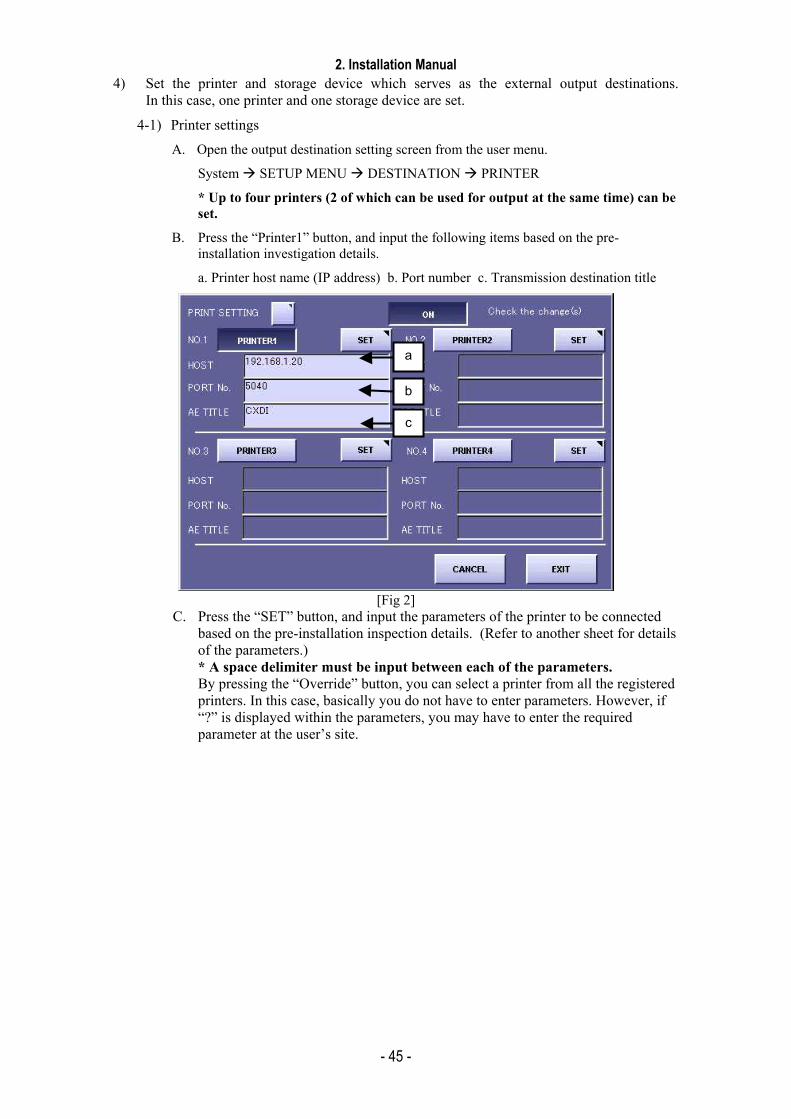
4-1) Printer settings
A. Open the output destination setting screen from the user menu.
System SETUP MENU DESTINATION PRINTER
* Up to four printers (2 of which can be used for output at the same time) can be set.
B. Press the “Printer1” button, and input the following items based on the pre-installation investigation details.
a. Printer host name (IP address) b. Port number c. Transmission destination title
[Fig 2]
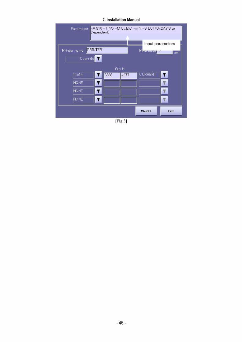
C. Press the “SET” button, and input the parameters of the printer to be connected based on the pre-installation inspection details. (Refer to another sheet for details of the parameters.) * A space delimiter must be input between each of the parameters. By pressing the “Override” button, you can select a printer from all the registered printers. In this case, basically you do not have to enter parameters. However, if “?” is displayed within the parameters, you may have to enter the required parameter at the user’s site.
a
b
c
2. Installation Manual
- 46 -
[Fig 3]
Input parameters
2. Installation Manual
- 47 -
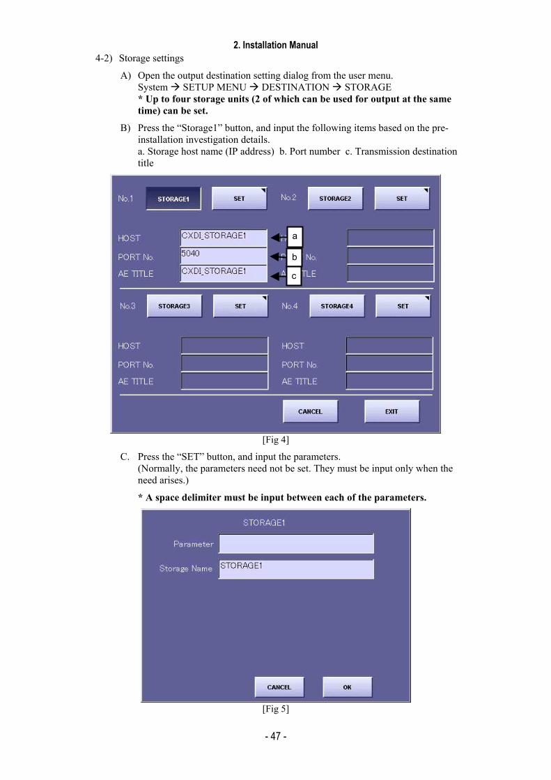
4-2) Storage settings
A) Open the output destination setting dialog from the user menu. System SETUP MENU DESTINATION STORAGE * Up to four storage units (2 of which can be used for output at the same time) can be set.
B) Press the “Storage1” button, and input the following items based on the pre-installation investigation details. a. Storage host name (IP address) b. Port number c. Transmission destination title
[Fig 4]
C. Press the “SET” button, and input the parameters. (Normally, the parameters need not be set. They must be input only when the need arises.)
* A space delimiter must be input between each of the parameters.
[Fig 5]
a
b
c
2. Installation Manual
- 48 -
D. After setting the output destinations, follow the procedure below to check whether images can actually be transmitted. Return to the user menu, capture a sample image (one X-ray image), and transmit the image to the printer and storage. There are two errors that may result if the image cannot be transmitted:
a. “DICOM Connect Error. Cannot connect to the target. Check network or port number setting. Retry?”
b. “DICOM Transfer Error. Error occurred during the association. Retry?”
Message (a) indicates that connection at the TCP/IP level is not possible and that the physical connections or the subnet mask and other settings must be checked again.
Message (b) indicates that communication at the TCP/IP level is problem-free but that DICOM level communication has failed. In this case, check again that AE_TITLE of CXDI has been sent properly to the transmission destination and that the IP address, port number and AE_TITLE of the transmission destination which are set with CXDI have been set properly.
* “AE_TITLE” of the transmission destination is case sensitive fields. (Permit upper-case letter or lower case letter, etc)
2. Installation Manual
- 49 -
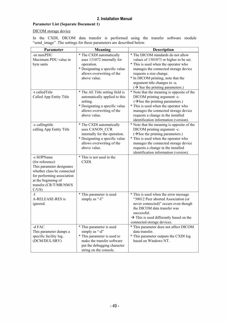
Parameter List (Separate Document 1)
DICOM storage device
In the CXDI, DICOM data transfer is performed using the transfer software module “send_image” .The settings for these parameters are described below.
Parameter Meaning Description -m maxPDU Maximum PDU value in byte units
* The CXDI automatically uses 131072 internally for operation.
* Designating a specific value allows overwriting of the above value.
* The DICOM standards do not allow values of 1301073 or higher to be set.
* This is used when the operator who manages the connected storage device requests a size change.
* In DICOM printing, note that the argument title changes to -u. ( See the printing parameters.)
-t calledTitle Called App Entity Title
* The AE Title setting field is automatically applied to this setting.
* Designating a specific value allows overwriting of the above value.
* Note that the meaning is opposite of the DICOM printing argument -c. ( See the printing parameters.)
* This is used when the operator who manages the connected storage device requests a change in the installed identification information (version).
-c callingtitle calling App Entity Title
* The CXDI automatically uses CANON_CCR internally for the operation.
* Designating a specific value allows overwriting of the above value.
* Note that the meaning is opposite of the DICOM printing argument -c. ( See the printing parameters.)
* This is used when the operator who manages the connected storage device requests a change in the installed identification information (version).
-s SOPName (for reference) This parameter designates whether class be connected for performing association at the beginning of transfer.(CR/T/MR/NM/SC/US)
* This is not used in the CXDI.
-I A-RELEASE-RES is ignored.
* This parameter is used simply as “-I”
* This is used when the error message “30012 Peer aborted Association (or never connected)” occurs even though the DICOM data transfer was successful. This is used differently based on the
connected storage devices. -d FAC This parameter dumps a specific facility log. (DCM/DUL/SRV)
* This parameter is used simply as “-d”
* This parameter is used to make the transfer software put the debugging character string on the console.
* This parameter does not affect DICOM data transfer.
* This parameter outputs the CXDI log based on Windows NT.
2. Installation Manual
- 50 -
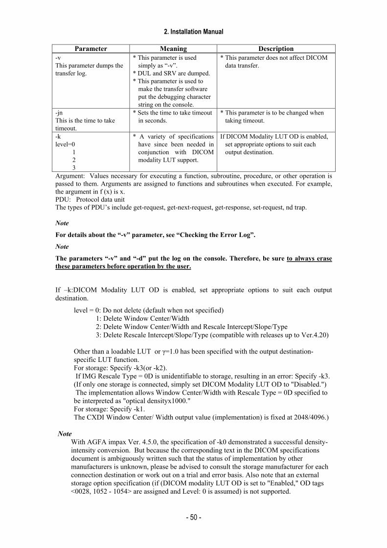
Parameter Meaning Description
-v This parameter dumps the transfer log.
* This parameter is used simply as “-v”.
* DUL and SRV are dumped. * This parameter is used to
make the transfer software put the debugging character string on the console.
* This parameter does not affect DICOM data transfer.
-jn This is the time to take timeout.
* Sets the time to take timeout in seconds.
* This parameter is to be changed when taking timeout.
-k level=0
1 2 3
* A variety of specifications have since been needed in conjunction with DICOM modality LUT support.
If DICOM Modality LUT OD is enabled, set appropriate options to suit each output destination.
Argument: Values necessary for executing a function, subroutine, procedure, or other operation is passed to them. Arguments are assigned to functions and subroutines when executed. For example, the argument in f (x) is x. PDU: Protocol data unit The types of PDU’s include get-request, get-next-request, get-response, set-request, nd trap. Note
For details about the “-v” parameter, see “Checking the Error Log”.
Note
The parameters “-v” and “-d” put the log on the console. Therefore, be sure to always erase these parameters before operation by the user.
If –k:DICOM Modality LUT OD is enabled, set appropriate options to suit each output destination.
level = 0: Do not delete (default when not specified) 1: Delete Window Center/Width 2: Delete Window Center/Width and Rescale Intercept/Slope/Type 3: Delete Rescale Intercept/Slope/Type (compatible with releases up to Ver.4.20)
Other than a loadable LUT or γ=1.0 has been specified with the output destination-specific LUT function. For storage: Specify -k3(or -k2). If IMG Rescale Type = 0D is unidentifiable to storage, resulting in an error: Specify -k3. (If only one storage is connected, simply set DICOM Modality LUT OD to "Disabled.") The implementation allows Window Center/Width with Rescale Type = 0D specified to be interpreted as "optical densityx1000." For storage: Specify -k1. The CXDI Window Center/ Width output value (implementation) is fixed at 2048/4096.)
Note
With AGFA impax Ver. 4.5.0, the specification of -k0 demonstrated a successful density-intensity conversion. But because the corresponding text in the DICOM specifications document is ambiguously written such that the status of implementation by other manufacturers is unknown, please be advised to consult the storage manufacturer for each connection destination or work out on a trial and error basis. Also note that an external storage option specification (if (DICOM modality LUT OD is set to "Enabled," OD tags <0028, 1052 - 1054> are assigned and Level: 0 is assumed) is not supported.
2. Installation Manual
- 51 -
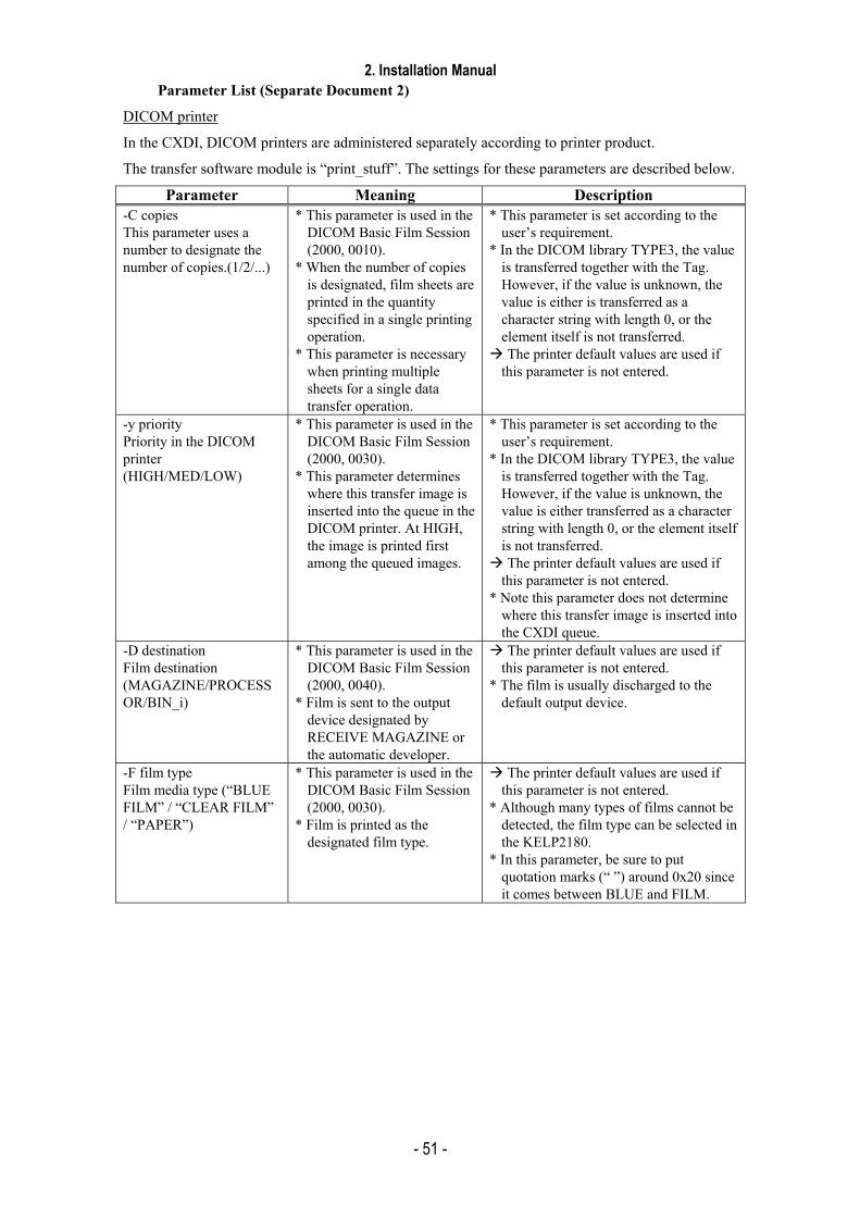
Parameter List (Separate Document 2)
DICOM printer
In the CXDI, DICOM printers are administered separately according to printer product.
The transfer software module is “print_stuff”. The settings for these parameters are described below.
Parameter Meaning Description -C copies This parameter uses a number to designate the number of copies.(1/2/...)
* This parameter is used in the DICOM Basic Film Session (2000, 0010).
* When the number of copies is designated, film sheets are printed in the quantity specified in a single printing operation.
* This parameter is necessary when printing multiple sheets for a single data transfer operation.
* This parameter is set according to the user’s requirement.
* In the DICOM library TYPE3, the value is transferred together with the Tag. However, if the value is unknown, the value is either is transferred as a character string with length 0, or the element itself is not transferred. The printer default values are used if this parameter is not entered.
-y priority Priority in the DICOM printer (HIGH/MED/LOW)
* This parameter is used in the DICOM Basic Film Session (2000, 0030).
* This parameter determines where this transfer image is inserted into the queue in the DICOM printer. At HIGH, the image is printed first among the queued images.
* This parameter is set according to the user’s requirement.
* In the DICOM library TYPE3, the value is transferred together with the Tag. However, if the value is unknown, the value is either transferred as a character string with length 0, or the element itself is not transferred. The printer default values are used if this parameter is not entered.
* Note this parameter does not determine where this transfer image is inserted into the CXDI queue.
-D destination Film destination (MAGAZINE/PROCESSOR/BIN_i)
* This parameter is used in the DICOM Basic Film Session (2000, 0040).
* Film is sent to the output device designated by RECEIVE MAGAZINE or the automatic developer.
The printer default values are used if this parameter is not entered.
* The film is usually discharged to the default output device.
-F film type Film media type (“BLUE FILM” / “CLEAR FILM” / “PAPER”)
* This parameter is used in the DICOM Basic Film Session (2000, 0030).
* Film is printed as the designated film type.
The printer default values are used if this parameter is not entered.
* Although many types of films cannot be detected, the film type can be selected in the KELP2180.
* In this parameter, be sure to put quotation marks (“ ”) around 0x20 since it comes between BLUE and FILM.

2. Installation Manual
- 52 -
-L sessionLabel Film session label (character string)
* This parameter is used in the DICOM Basic Film Session (2000, 0050).
* The label for the film session is for designation purposes only, and generally it is not displayed directly on the print image.
The parameter is not transferred over DICOM if it is not designated. * This parameter may be displayed in
some form or another depending on the installed printer. For example, it may be displayed in the Control Panel for the printer or in the corner of the film.
-f films Number of film box to be printed
* Currently, this parameter is not operating.
–i Format Format at print
* This parameter is used in the DICOM Basic Film Box (2010, 0010).
* This is not necessary, as for automatically designated on CXDI.
* If this parameter is not designated, transfer software uses automatically STANDARD1 1, for reason this parameter must be transferred in the DICOM.
-l FilmSizeID Film size 14 inch x 17 inch / 17 inch x 14 inch / 11 inch x 14 inch / -l FilmSizeID / 10 inch x 14 inch 10 inch x 12 inch / 24 cm x 24 cm / 24 cm x 30 cm
* This parameter is used in the DICOM Basic Film Box (2010, 0050).
* This parameter designates the size of the film to be printed
The parameter is not transferred over DICOM if it is not designated. In this case, the printer default values are used. When this parameter is not transferred, problems can occur since unsuitable default values may be used. * Some printers do not print until a supply
magazine of the designated size is loaded, and others print even though the designated size is different from the currently loaded supply magazine.
-M magnification Interpolation method (NONE/REPLICATE/BILINEAR/CUBIC)
* This parameter is used in the DICOM Basic Film Box (2010, 0060).
* This parameter designates the interpolation method since the printer has a higher resolution than the CXDI in most cases.
* Generally, CUBIC provides the best results, followed by BILINEAR. The REPLICATE option is not suitable for CXDI image applications.
The printer default values are used if this parameter is not entered. When this parameter is not transferred, problems can occur since unsuitable default values may be used.
-m smoothing Type of smoothing (character string)
* This parameter is used in the DICOM Basic Film Box (2010, 0080).
* This parameter designates the smoothing method for the image.
* In the DICOM standards, this parameter setting is valid only when CUBIC is selected for the magnification parameter above.
* In the DICOM standards, value to be transferred is not predetermined.
The parameter is not transferred over DICOM if it is not designated. In this case, the printer default values are used. When this parameter is not transferred, problems can occur since unsuitable default values may be used. * This parameter is determined by asking
the printer engineer or by viewing the conformance statement.
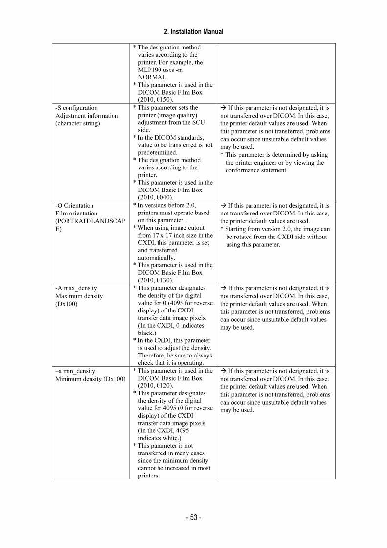
2. Installation Manual
- 53 -
* The designation method
varies according to the printer. For example, the MLP190 uses -m NORMAL.
* This parameter is used in the DICOM Basic Film Box (2010, 0150).
-S configuration Adjustment information (character string)
* This parameter sets the printer (image quality) adjustment from the SCU side.
* In the DICOM standards, value to be transferred is not predetermined.
* The designation method varies according to the printer.
* This parameter is used in the DICOM Basic Film Box (2010, 0040).
If this parameter is not designated, it is not transferred over DICOM. In this case, the printer default values are used. When this parameter is not transferred, problems can occur since unsuitable default values may be used. * This parameter is determined by asking
the printer engineer or by viewing the conformance statement.
-O Orientation Film orientation (PORTRAIT/LANDSCAPE)
* In versions before 2.0, printers must operate based on this parameter.
* When using image cutout from 17 x 17 inch size in the CXDI, this parameter is set and transferred automatically.
* This parameter is used in the DICOM Basic Film Box (2010, 0130).
If this parameter is not designated, it is not transferred over DICOM. In this case, the printer default values are used. * Starting from version 2.0, the image can
be rotated from the CXDI side without using this parameter.
-A max_density Maximum density (Dx100)
* This parameter designates the density of the digital value for 0 (4095 for reverse display) of the CXDI transfer data image pixels. (In the CXDI, 0 indicates black.)
* In the CXDI, this parameter is used to adjust the density. Therefore, be sure to always check that it is operating.
If this parameter is not designated, it is not transferred over DICOM. In this case, the printer default values are used. When this parameter is not transferred, problems can occur since unsuitable default values may be used.
–a min_density Minimum density (Dx100)
* This parameter is used in the DICOM Basic Film Box (2010, 0120).
* This parameter designates the density of the digital value for 4095 (0 for reverse display) of the CXDI transfer data image pixels. (In the CXDI, 4095 indicates white.)
* This parameter is not transferred in many cases since the minimum density cannot be increased in most printers.
If this parameter is not designated, it is not transferred over DICOM. In this case, the printer default values are used. When this parameter is not transferred, problems can occur since unsuitable default values may be used.
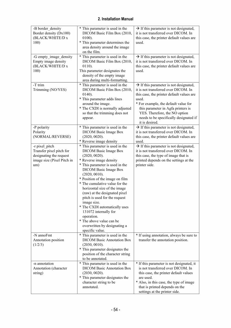
2. Installation Manual
- 54 -
-B border_density Border density (Dx100) (BLACK/WHITE/D x 100)
* This parameter is used in the DICOM Basic Film Box (2010, 0100).
* This parameter determines the area density around the image on the film.
If this parameter is not designated, it is not transferred over DICOM. In this case, the printer default values are used.
-G empty_image_density Empty image density (BLACK/WHITE/D x 100)
* This parameter is used in the DICOM Basic Film Box (2010, 0110).
This parameter designates the density of the empty image area during multi-formatting.
If this parameter is not designated, it is not transferred over DICOM. In this case, the printer default values are used.
-T trim Trimming (NO/YES)
* This parameter is used in the DICOM Basic Film Box (2010, 0140).
* This parameter adds lines around the image.
* The CXDI is normally adjusted so that the trimming does not appear.
If this parameter is not designated, it is not transferred over DICOM. In this case, the printer default values are used. * For example, the default value for
this parameter in Agfa printers is YES. Therefore, the NO option needs to be specifically designated if it is desired.
-P polarity Polarity (NORMAL/REVERSE)
* This parameter is used in the DICOM Basic Image Box (2020, 0020).
* Reverse image density
If this parameter is not designated, it is not transferred over DICOM. In this case, the printer default values are used.
-r pixel_pitch Transfer pixel pitch for designating the request image size (Pixel Pitch in um)
* This parameter is used in the DICOM Basic Image Box (2020, 0020).
* Reverse image density * This parameter is used in the
DICOM Basic Image Box (2020, 0010).
* Position of the image on film * The cumulative value for the
horizontal size of the image (raw) at the designated pixel pitch is used for the request image size.
* The CXDI automatically uses 131072 internally for operation.
* The above value can be overwritten by designating a specific value.
If this parameter is not designated, it is not transferred over DICOM. In this case, the type of image that is printed depends on the settings at the printer side.
-N annoFmt Annotation position (1/2/3)
* This parameter is used in the DICOM Basic Annotation Box (2030, 0010).
* This parameter designates the position of the character string to be annotated.
* If using annotation, always be sure to transfer the annotation position.
-n annotation Annotation (character string)
* This parameter is used in the DICOM Basic Annotation Box (2030, 0020).
* This parameter designates the character string to be annotated.
* If this parameter is not designated, it is not transferred over DICOM. In this case, the printer default values are used.
* Also, in this case, the type of image that is printed depends on the settings at the printer side.
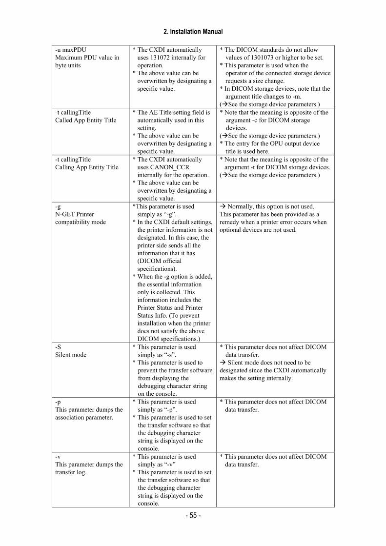
2. Installation Manual
- 55 -
-u maxPDU Maximum PDU value in byte units
* The CXDI automatically uses 131072 internally for operation.
* The above value can be overwritten by designating a specific value.
* The DICOM standards do not allow values of 1301073 or higher to be set.
* This parameter is used when the operator of the connected storage device requests a size change.
* In DICOM storage devices, note that the argument title changes to -m.
( See the storage device parameters.) -t callingTitle Called App Entity Title
* The AE Title setting field is automatically used in this setting.
* The above value can be overwritten by designating a specific value.
* Note that the meaning is opposite of the argument -c for DICOM storage devices.
( See the storage device parameters.) * The entry for the OPU output device
title is used here. -t callingTitle Calling App Entity Title
* The CXDI automatically uses CANON_CCR internally for the operation.
* The above value can be overwritten by designating a specific value.
* Note that the meaning is opposite of the argument -t for DICOM storage devices.
( See the storage device parameters.)
-g N-GET Printer compatibility mode
*This parameter is used simply as “-g”.
* In the CXDI default settings, the printer information is not designated. In this case, the printer side sends all the information that it has (DICOM official specifications).
* When the -g option is added, the essential information only is collected. This information includes the Printer Status and Printer Status Info. (To prevent installation when the printer does not satisfy the above DICOM specifications.)
Normally, this option is not used. This parameter has been provided as a remedy when a printer error occurs when optional devices are not used.
-S Silent mode
* This parameter is used simply as “-s”.
* This parameter is used to prevent the transfer software from displaying the debugging character string on the console.
* This parameter does not affect DICOM data transfer. Silent mode does not need to be
designated since the CXDI automatically makes the setting internally.
-p This parameter dumps the association parameter.
* This parameter is used simply as “-p”.
* This parameter is used to set the transfer software so that the debugging character string is displayed on the console.
* This parameter does not affect DICOM data transfer.
-v This parameter dumps the transfer log.
* This parameter is used simply as “-v”
* This parameter is used to set the transfer software so that the debugging character string is displayed on the console.
* This parameter does not affect DICOM data transfer.
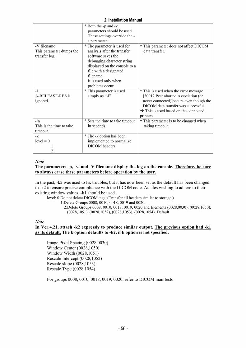
2. Installation Manual
- 56 -
* Both the -p and -v parameters should be used. These settings override the -s parameter.
-V filename This parameter dumps the transfer log.
* The parameter is used for analysis after the transfer software saves the debugging character string displayed on the console to a file with a designated filename. It is used only when problems occur.
* This parameter does not affect DICOM data transfer.
-I A-RELEASE-RES is ignored.
* This parameter is used simply as “-I”
* This is used when the error message [30012 Peer aborted Association (or never connected)]occurs even though the DICOM data transfer was successful. This is used based on the connected
printers. -jn This is the time to take timeout.
* Sets the time to take timeout in seconds.
* This parameter is to be changed when taking timeout.
-k level = 0
1 2
* The -k option has been implemented to normalize DICOM headers
Note The parameters -p, -v, and -V filename display the log on the console. Therefore, be sure to always erase these parameters before operation by the user. In the past, -k2 was used to fix troubles, but it has now been set as the default has been changed to -k2 to ensure precise compliance with the DICOM code. At sites wishing to adhere to their existing window values, -k1 should be used.
level: 0:Do not delete DICOM tags. (Transfer all headers similar to storage.) 1:Delete Groups 0008, 0010, 0018, 0019 and 0020.
2:Delete Groups 0008, 0010, 0018, 0019, 0020 and Elements (0028,0030), (0028,1050), (0028,1051), (0028,1052), (0028,1053), (0028,1054). Default
Note In Ver.4.21, attach -k2 expressly to produce similar output. The previous option had -k1 as its default. The k option defaults to -k2, if k option is not specified.
Image Pixel Spacing (0028,0030) Window Center (0028,1050) Window Width (0028,1051) Rescale Intercept (0028,1052) Rescale slope (0028,1053) Rescale Type (0028,1054) For groups 0008, 0010, 0018, 0019, 0020, refer to DICOM manifesto.
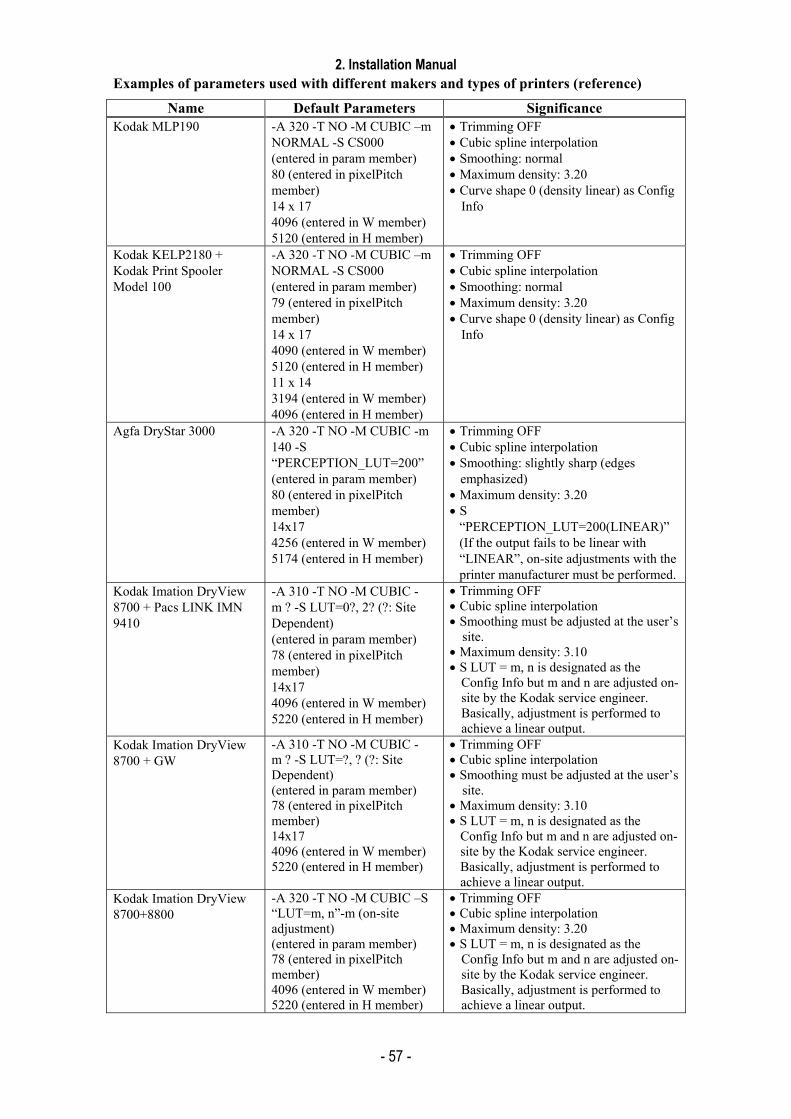
2. Installation Manual
- 57 -
Examples of parameters used with different makers and types of printers (reference)
Name Default Parameters Significance Kodak MLP190 -A 320 -T NO -M CUBIC –m
NORMAL -S CS000 (entered in param member) 80 (entered in pixelPitch member) 14 x 17 4096 (entered in W member) 5120 (entered in H member)
• Trimming OFF • Cubic spline interpolation • Smoothing: normal • Maximum density: 3.20 • Curve shape 0 (density linear) as Config
Info
Kodak KELP2180 + Kodak Print Spooler Model 100
-A 320 -T NO -M CUBIC –m NORMAL -S CS000 (entered in param member) 79 (entered in pixelPitch member) 14 x 17 4090 (entered in W member) 5120 (entered in H member) 11 x 14 3194 (entered in W member) 4096 (entered in H member)
• Trimming OFF • Cubic spline interpolation • Smoothing: normal • Maximum density: 3.20 • Curve shape 0 (density linear) as Config
Info
Agfa DryStar 3000 -A 320 -T NO -M CUBIC -m 140 -S “PERCEPTION_LUT=200” (entered in param member) 80 (entered in pixelPitch member) 14x17 4256 (entered in W member) 5174 (entered in H member)
• Trimming OFF • Cubic spline interpolation • Smoothing: slightly sharp (edges
emphasized) • Maximum density: 3.20 • S
“PERCEPTION_LUT=200(LINEAR)” (If the output fails to be linear with “LINEAR”, on-site adjustments with the printer manufacturer must be performed.
Kodak Imation DryView 8700 + Pacs LINK IMN 9410
-A 310 -T NO -M CUBIC -m ? -S LUT=0?, 2? (?: Site Dependent) (entered in param member) 78 (entered in pixelPitch member) 14x17 4096 (entered in W member) 5220 (entered in H member)
• Trimming OFF • Cubic spline interpolation • Smoothing must be adjusted at the user’s
site. • Maximum density: 3.10 • S LUT = m, n is designated as the
Config Info but m and n are adjusted on-site by the Kodak service engineer. Basically, adjustment is performed to achieve a linear output.
Kodak Imation DryView 8700 + GW
-A 310 -T NO -M CUBIC -m ? -S LUT=?, ? (?: Site Dependent) (entered in param member) 78 (entered in pixelPitch member) 14x17 4096 (entered in W member) 5220 (entered in H member)
• Trimming OFF • Cubic spline interpolation • Smoothing must be adjusted at the user’s
site. • Maximum density: 3.10 • S LUT = m, n is designated as the
Config Info but m and n are adjusted on-site by the Kodak service engineer. Basically, adjustment is performed to achieve a linear output.
Kodak Imation DryView 8700+8800
-A 320 -T NO -M CUBIC –S “LUT=m, n”-m (on-site adjustment) (entered in param member) 78 (entered in pixelPitch member) 4096 (entered in W member) 5220 (entered in H member)
• Trimming OFF • Cubic spline interpolation • Maximum density: 3.20 • S LUT = m, n is designated as the
Config Info but m and n are adjusted on-site by the Kodak service engineer. Basically, adjustment is performed to achieve a linear output.
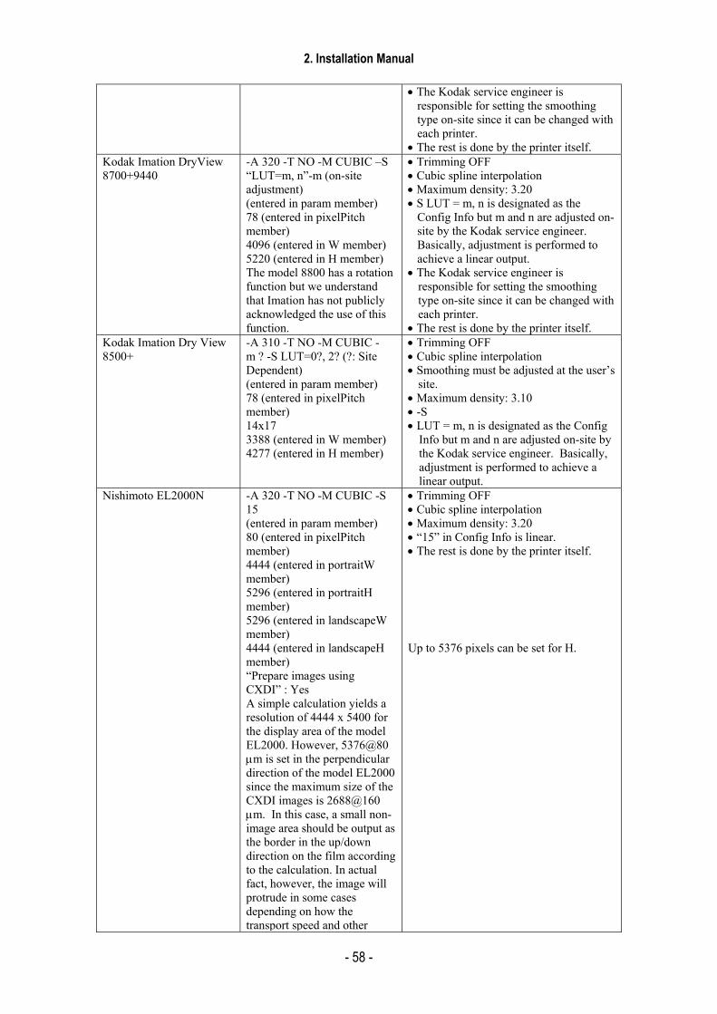
2. Installation Manual
- 58 -
• The Kodak service engineer is
responsible for setting the smoothing type on-site since it can be changed with each printer.
• The rest is done by the printer itself. Kodak Imation DryView 8700+9440
-A 320 -T NO -M CUBIC –S “LUT=m, n”-m (on-site adjustment) (entered in param member) 78 (entered in pixelPitch member) 4096 (entered in W member) 5220 (entered in H member) The model 8800 has a rotation function but we understand that Imation has not publicly acknowledged the use of this function.
• Trimming OFF • Cubic spline interpolation • Maximum density: 3.20 • S LUT = m, n is designated as the
Config Info but m and n are adjusted on-site by the Kodak service engineer. Basically, adjustment is performed to achieve a linear output.
• The Kodak service engineer is responsible for setting the smoothing type on-site since it can be changed with each printer.
• The rest is done by the printer itself. Kodak Imation Dry View 8500+
-A 310 -T NO -M CUBIC -m ? -S LUT=0?, 2? (?: Site Dependent) (entered in param member) 78 (entered in pixelPitch member) 14x17 3388 (entered in W member) 4277 (entered in H member)
• Trimming OFF • Cubic spline interpolation • Smoothing must be adjusted at the user’s
site. • Maximum density: 3.10 • -S • LUT = m, n is designated as the Config
Info but m and n are adjusted on-site by the Kodak service engineer. Basically, adjustment is performed to achieve a linear output.
Nishimoto EL2000N -A 320 -T NO -M CUBIC -S 15 (entered in param member) 80 (entered in pixelPitch member) 4444 (entered in portraitW member) 5296 (entered in portraitH member) 5296 (entered in landscapeW member) 4444 (entered in landscapeH member) “Prepare images using CXDI” : Yes A simple calculation yields a resolution of 4444 x 5400 for the display area of the model EL2000. However, 5376@80 µm is set in the perpendicular direction of the model EL2000 since the maximum size of the CXDI images is 2688@160 µm. In this case, a small non-image area should be output as the border in the up/down direction on the film according to the calculation. In actual fact, however, the image will protrude in some cases depending on how the transport speed and other
• Trimming OFF • Cubic spline interpolation • Maximum density: 3.20 • “15” in Config Info is linear. • The rest is done by the printer itself. Up to 5376 pixels can be set for H.
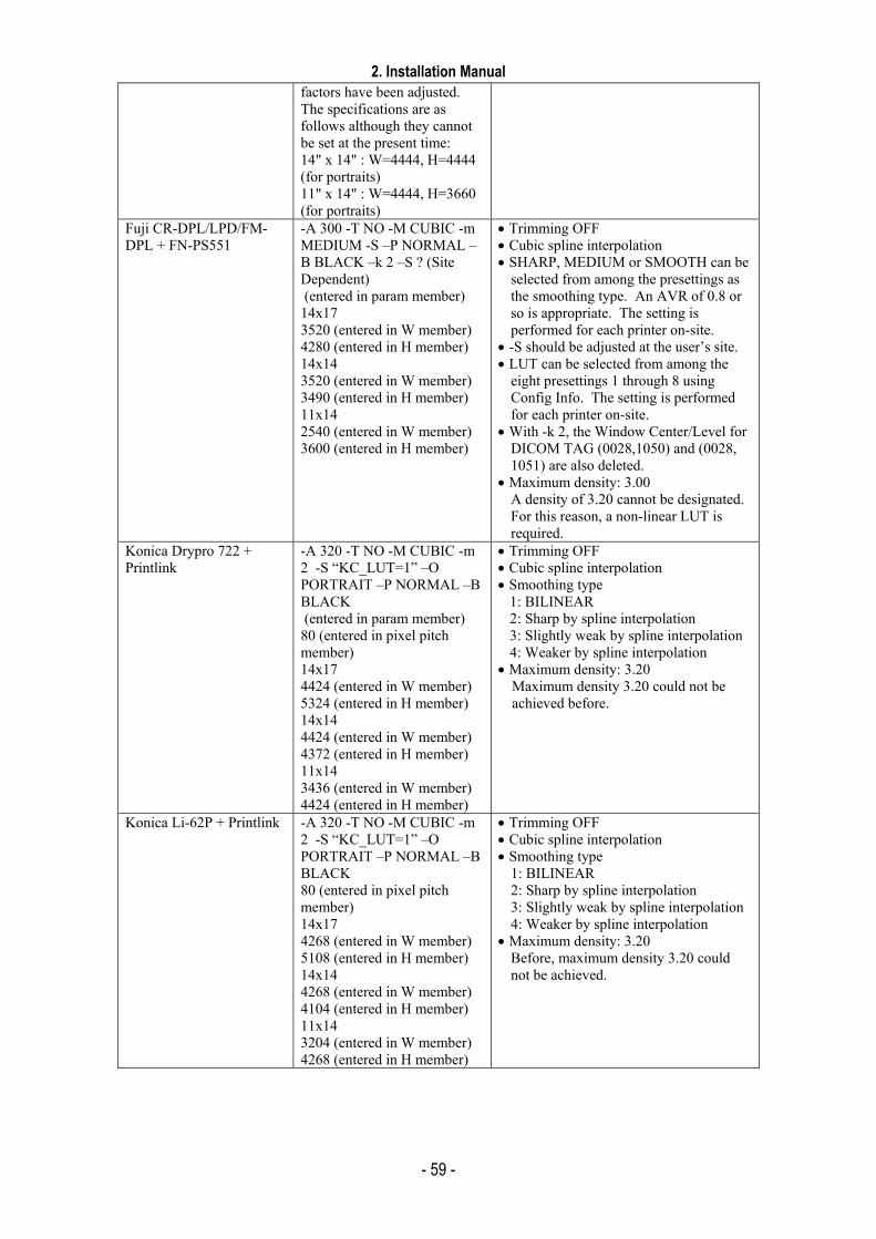
2. Installation Manual
- 59 -
factors have been adjusted. The specifications are as follows although they cannot be set at the present time: 14" x 14" : W=4444, H=4444 (for portraits) 11" x 14" : W=4444, H=3660 (for portraits)
Fuji CR-DPL/LPD/FM-DPL + FN-PS551
-A 300 -T NO -M CUBIC -m MEDIUM -S –P NORMAL –B BLACK –k 2 –S ? (Site Dependent) (entered in param member) 14x17 3520 (entered in W member) 4280 (entered in H member) 14x14 3520 (entered in W member) 3490 (entered in H member) 11x14 2540 (entered in W member) 3600 (entered in H member)
• Trimming OFF • Cubic spline interpolation • SHARP, MEDIUM or SMOOTH can be
selected from among the presettings as the smoothing type. An AVR of 0.8 or so is appropriate. The setting is performed for each printer on-site.
• -S should be adjusted at the user’s site. • LUT can be selected from among the
eight presettings 1 through 8 using Config Info. The setting is performed for each printer on-site.
• With -k 2, the Window Center/Level for DICOM TAG (0028,1050) and (0028, 1051) are also deleted.
• Maximum density: 3.00 A density of 3.20 cannot be designated. For this reason, a non-linear LUT is required.
Konica Drypro 722 + Printlink
-A 320 -T NO -M CUBIC -m 2 -S “KC_LUT=1” –O PORTRAIT –P NORMAL –B BLACK (entered in param member) 80 (entered in pixel pitch member) 14x17 4424 (entered in W member) 5324 (entered in H member) 14x14 4424 (entered in W member) 4372 (entered in H member) 11x14 3436 (entered in W member) 4424 (entered in H member)
• Trimming OFF • Cubic spline interpolation • Smoothing type
1: BILINEAR 2: Sharp by spline interpolation 3: Slightly weak by spline interpolation 4: Weaker by spline interpolation
• Maximum density: 3.20 Maximum density 3.20 could not be achieved before.
Konica Li-62P + Printlink -A 320 -T NO -M CUBIC -m 2 -S “KC_LUT=1” –O PORTRAIT –P NORMAL –B BLACK 80 (entered in pixel pitch member) 14x17 4268 (entered in W member) 5108 (entered in H member) 14x14 4268 (entered in W member) 4104 (entered in H member) 11x14 3204 (entered in W member) 4268 (entered in H member)
• Trimming OFF • Cubic spline interpolation • Smoothing type
1: BILINEAR 2: Sharp by spline interpolation 3: Slightly weak by spline interpolation 4: Weaker by spline interpolation
• Maximum density: 3.20 Before, maximum density 3.20 could not be achieved.

2. Installation Manual
- 60 -
Printer Model Specifications (Reference)
Name Specifications Maximum equivalent area in CXDI
Kodak MLP190 80µm x 4096 x 5120 2048 x 2560 (@160 µm)Kodak KELP2180 + Kodak Print Spooler Model 100
79 µm x 4090 x 5120 (value after passing through the print spooler) • The above settings are the size of the effective area
when the image passes through the print spooler and the image is plotted up to the annotation area. In other words, these settings do not display an annotation area, instead handling it as an image area.
• If the data is transferred without setting [Image creation in CXDI], the Requested Image Size setting is used in DICOM. In this case, the annotation area is automatically displayed in the 2180 printer. As a result, a maximum image area of 79 µm x 4090 x 4996 must be designated. In this case, the CXDI relies on the 2180 for image rotation (Film Orientation), but images larger than 1.7 MB cannot be rotated by the 2180. Therefore, operation without the setting for [Image creation in CXDI] cannot be performed in the 2180. (Although operation is possible by setting Requested Image Size only for using DICOM without the setting for [Image creation in CXDI], this option is not installed in the CXDI.)
• Although the resolution of the printer itself is 79 µm x 4090 x 5260, this complete resolution cannot be used when the image passes through the spooler. When “_” is used in AE Title, the association is rejected. Use the Disable function for N-EVENT-REPORT to disable this setting. The FilmSize parameter can be used. The MediaType (BLUE, CLEAR) parameter is also supported.
• Although the Film Orientation parameter is supported up to 1.7 MB, in actuality, DR images cannot be rotated. Like the DryView8700, the images must be rotated by the CXDI side.
• When Requested Image Size is expanded, the maximum plotting size is limited (79 um x 4090 x 4996) so that the annotation area can be obtained. When a Requested Image Size expansion error occurs, the image is interpolated and printed at the suitable size. In this case, the error does not return to the CXDI side. For example, the image is printed at 310 mm even if 326 mm is designated.
• If an expansion error occurs in the spooler when Multi Display Format is used, the print queue cannot be processed.
• The system is in a critical state when a Failure status is indicated. A user message is displayed indicating this state, and images are no longer transferred. (Fully installed)
• During the Warning status, image transfer is performed while the user message is displayed (Fully installed).
• If operation is aborted due to an error, a new association could not be established when the data was resent from the CXDI. GW was reset to recover the error.
2018 x 2528(@160 µm)
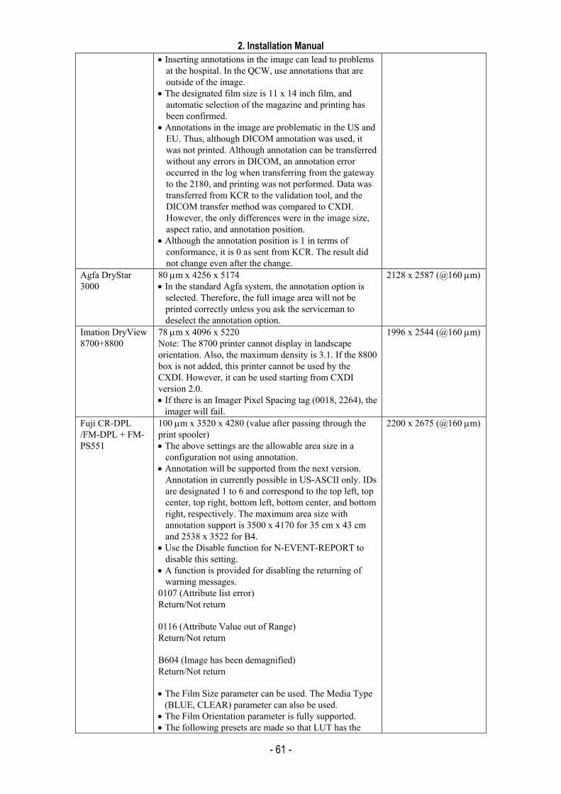
2. Installation Manual
- 61 -
• Inserting annotations in the image can lead to problems at the hospital. In the QCW, use annotations that are outside of the image.
• The designated film size is 11 x 14 inch film, and automatic selection of the magazine and printing has been confirmed.
• Annotations in the image are problematic in the US and EU. Thus, although DICOM annotation was used, it was not printed. Although annotation can be transferred without any errors in DICOM, an annotation error occurred in the log when transferring from the gateway to the 2180, and printing was not performed. Data was transferred from KCR to the validation tool, and the DICOM transfer method was compared to CXDI. However, the only differences were in the image size, aspect ratio, and annotation position.
• Although the annotation position is 1 in terms of conformance, it is 0 as sent from KCR. The result did not change even after the change.
Agfa DryStar 3000
80 µm x 4256 x 5174 • In the standard Agfa system, the annotation option is
selected. Therefore, the full image area will not be printed correctly unless you ask the serviceman to deselect the annotation option.
2128 x 2587 (@160 µm)
Imation DryView 8700+8800
78 µm x 4096 x 5220 Note: The 8700 printer cannot display in landscape orientation. Also, the maximum density is 3.1. If the 8800 box is not added, this printer cannot be used by the CXDI. However, it can be used starting from CXDI version 2.0. • If there is an Imager Pixel Spacing tag (0018, 2264), the
imager will fail.
1996 x 2544 (@160 µm)
Fuji CR-DPL /FM-DPL + FM-PS551
100 µm x 3520 x 4280 (value after passing through the print spooler) • The above settings are the allowable area size in a
configuration not using annotation. • Annotation will be supported from the next version.
Annotation in currently possible in US-ASCII only. IDs are designated 1 to 6 and correspond to the top left, top center, top right, bottom left, bottom center, and bottom right, respectively. The maximum area size with annotation support is 3500 x 4170 for 35 cm x 43 cm and 2538 x 3522 for B4.
• Use the Disable function for N-EVENT-REPORT to disable this setting.
• A function is provided for disabling the returning of warning messages.
0107 (Attribute list error) Return/Not return 0116 (Attribute Value out of Range) Return/Not return B604 (Image has been demagnified) Return/Not return • The Film Size parameter can be used. The Media Type
(BLUE, CLEAR) parameter can also be used. • The Film Orientation parameter is fully supported. • The following presets are made so that LUT has the
2200 x 2675 (@160 µm)
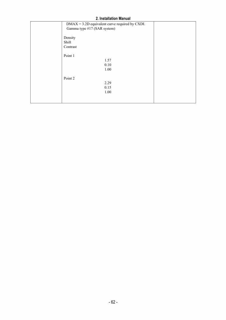
2. Installation Manual
- 62 -
DMAX = 3.2D equivalent curve required by CXDI. Gamma type #17 (SAR system)
Density Shift Contrast Point 1
1.57 0.10 1.00
Point 2
2.29 0.15 1.00
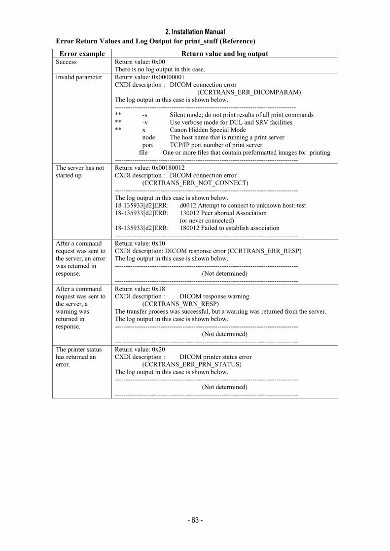
2. Installation Manual
- 63 -
Error Return Values and Log Output for print_stuff (Reference)
Error example Return value and log output Success Return value: 0x00
There is no log output in this case. Invalid parameter Return value: 0x00000001
CXDI description : DICOM connection error (CCRTRANS_ERR_DICOMPARAM) The log output in this case is shown below. ----------------------------------------------------------------------------------- ** -s Silent mode; do not print results of all print commands ** -v Use verbose mode for DUL and SRV facilities ** x Canon Hidden Special Mode node The host name that is running a print server port TCP/IP port number of print server file One or more files that contain preformatted images for printing ------------------------------------------------------------------------------------
The server has not started up.
Return value: 0x00180012 CXDI description : DICOM connection error (CCRTRANS_ERR_NOT_CONNECT) ------------------------------------------------------------------------------------ The log output in this case is shown below. 18-135933[d2]ERR: d0012 Attempt to connect to unknown host: test 18-135933[d2]ERR: 130012 Peer aborted Association (or never connected) 18-135933[d2]ERR: 180012 Failed to establish association ------------------------------------------------------------------------------------
After a command request was sent to the server, an error was returned in response.
Return value: 0x10 CXDI description: DICOM response error (CCRTRANS_ERR_RESP) The log output in this case is shown below. ------------------------------------------------------------------------------------
(Not determined) ------------------------------------------------------------------------------------
After a command request was sent to the server, a warning was returned in response.
Return value: 0x18 CXDI description : DICOM response warning (CCRTRANS_WRN_RESP) The transfer process was successful, but a warning was returned from the server. The log output in this case is shown below. ------------------------------------------------------------------------------------
(Not determined) ------------------------------------------------------------------------------------
The printer status has returned an error.
Return value: 0x20 CXDI description : DICOM printer status error (CCRTRANS_ERR_PRN_STATUS) The log output in this case is shown below. ------------------------------------------------------------------------------------
(Not determined) ------------------------------------------------------------------------------------

2. Installation Manual
- 64 -
The printer status has returned a warning.
Return value: 0x28 CXDI description: DICOM printer status warning (CCRTRANS_WRN_PRN_STATUS) The transfer process was successful, but a warning was returned as the printer status. The log output in this case is shown below. ------------------------------------------------------------------------------------
(Not determined) ------------------------------------------------------------------------------------
Other errors Return value: Values other than those above CXDI description : DICOM communications error (CCRTRANS_ERR_DICOM_TRANSE) The log output in this case depends on the specific error. A typical example is shown below. ------------------------------------------------------------------------------------ 18-140933[d2]ERR : c0082 SRV Send (DATA SET) failed in SRV_SendDataSet 18-140933[d2]ERR : 190082 SRV Request failed in SRV_NCreateRequest 18-140933[d2]ERR : 70012 NULL_key passed to routineDUL_ReleaseAssociation ------------------------------------------------------------------------------------
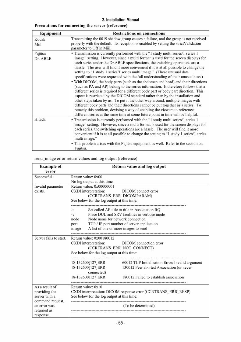
2. Installation Manual
- 65 -
Precautions for connecting the server (reference)
Equipment Restrictions on connections Kodak Miil
Transmitting the 0019 shadow group causes a failure, and the group is not received properly with the default. Its reception is enabled by setting the strictValidation parameter to Off in Miil.
Fujitsu Dr. ABLE
Transmission is currently performed with the “1 study multi series/1 series 1 image” setting. However, since a multi format is used for the screen displays for each series under the Dr.ABLE specifications, the switching operations are a hassle. The user will find it more convenient if it is at all possible to change the setting to “1 study 1 series/1 series multi image.” (These unusual data specifications were requested with the full understanding of their unusualness.)
With DICOM, the body parts (such as the abdomen and head) and their directions (such as PA and AP) belong to the series information. It therefore follows that a different series is required for a different body part or body part direction. This aspect is restricted by the DICOM standard rather than by the installation and other steps taken by us. To put it the other way around, multiple images with different body parts and their directions cannot be put together as a series. To remedy this problem, devising a way of enabling the viewers to reference different series at the same time at some future point in time will be helpful.
Hitachi Transmission is currently performed with the “1 study multi series/1 series 1 image” setting. However, since a multi format is used for the screen displays for each series, the switching operations are a hassle. The user will find it more convenient if it is at all possible to change the setting to “1 study 1 series/1 series multi image.”
This problem arises with the Fujitsu equipment as well. Refer to the section on Fujitsu.
send_image error return values and log output (reference)
Example of error
Return value and log output
Successful Return value: 0x00 No log output at this time
Invalid parameter exists.
Return value: 0x00000001 CXDI interpretation: DICOM connect error (CCRTRANS_ERR_DICOMPARAM) See below for the log output at this time: ------------------------------------------------------------------------------------- -t Set called AE title to title in Association RQ -v Place DUL and SRV facilities in verbose mode node Node name for network connection port TCP / IP port number of server application image A list of one or more images to send -------------------------------------------------------------------------------------
Server fails to start. Return value: 0x00180012 CXDI interpretation: DICOM connection error (CCRTRANS_ERR_NOT_CONNECT) See below for the log output at this time: ------------------------------------------------------------------------------------- 18-132600[127]ERR: 60012 TCP Initialization Error: Invalid argument 18-132600[127]ERR: 130012 Peer aborted Association (or never connected) 18-132600[127]ERR: 180012 Failed to establish association -------------------------------------------------------------------------------------
As a result of providing the server with a command request, an error was returned as response.
Return value: 0x10 CXDI interpretation: DICOM response error (CCRTRANS_ERR_RESP) See below for the log output at this time: -------------------------------------------------------------------------------------
(To be determined) -------------------------------------------------------------------------------------
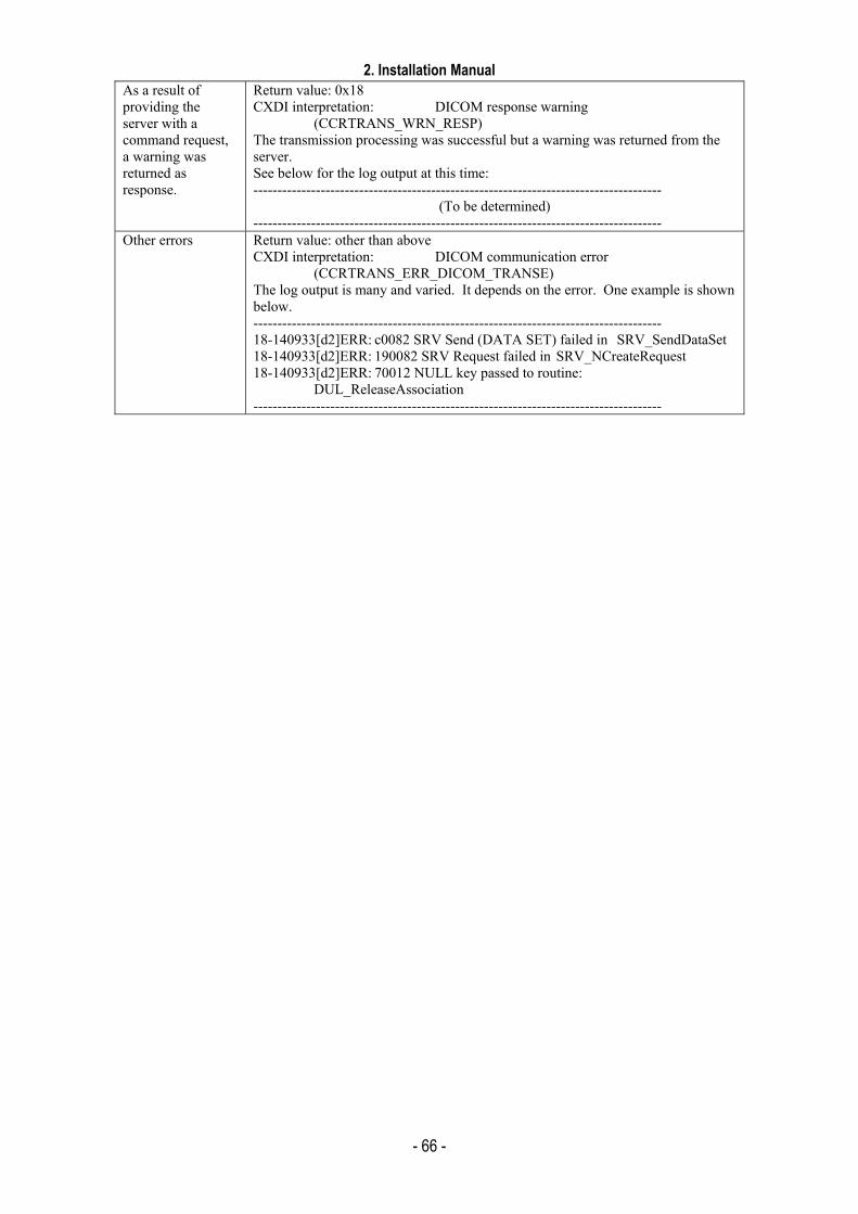
2. Installation Manual
- 66 -
As a result of providing the server with a command request, a warning was returned as response.
Return value: 0x18 CXDI interpretation: DICOM response warning (CCRTRANS_WRN_RESP) The transmission processing was successful but a warning was returned from the server. See below for the log output at this time: -------------------------------------------------------------------------------------
(To be determined) -------------------------------------------------------------------------------------
Other errors Return value: other than above CXDI interpretation: DICOM communication error (CCRTRANS_ERR_DICOM_TRANSE) The log output is many and varied. It depends on the error. One example is shown below. ------------------------------------------------------------------------------------- 18-140933[d2]ERR: c0082 SRV Send (DATA SET) failed in SRV_SendDataSet 18-140933[d2]ERR: 190082 SRV Request failed in SRV_NCreateRequest 18-140933[d2]ERR: 70012 NULL key passed to routine: DUL_ReleaseAssociation -------------------------------------------------------------------------------------
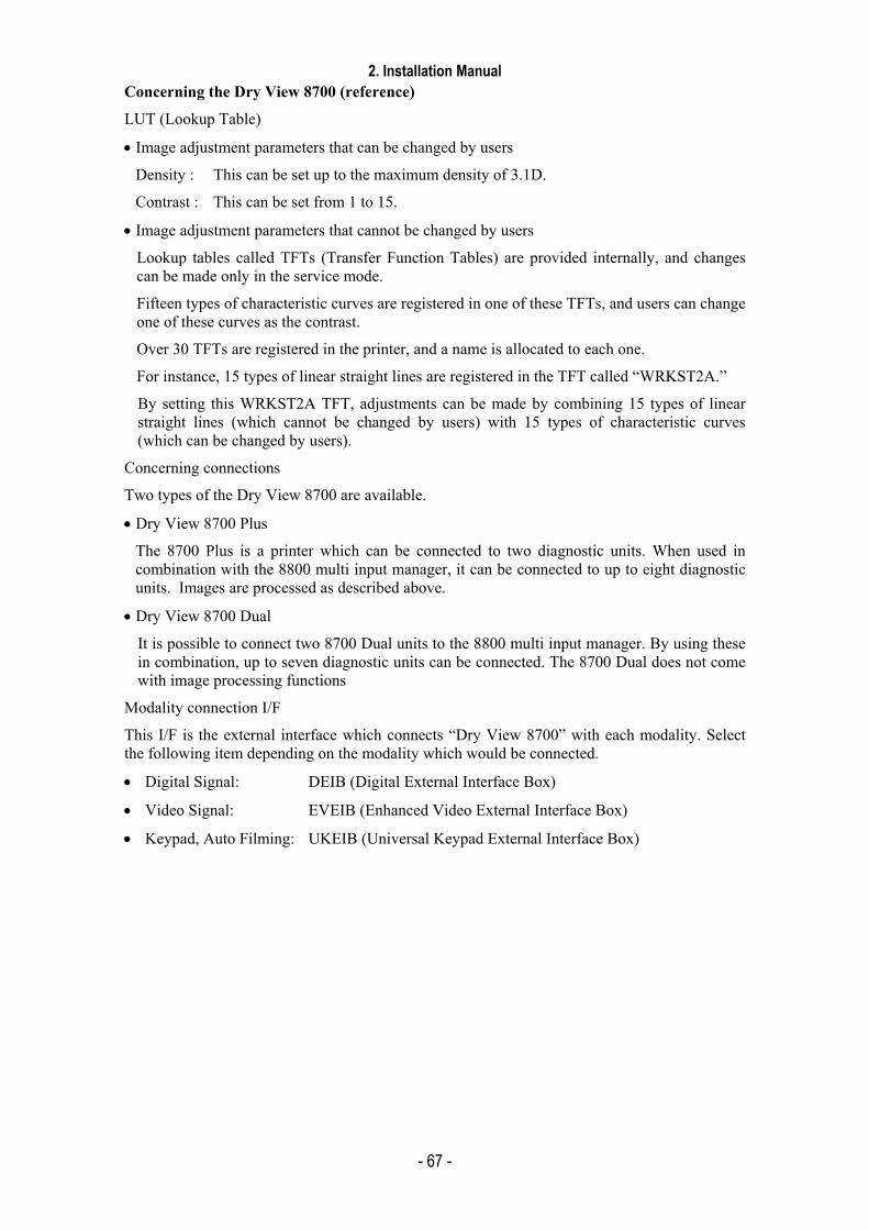
2. Installation Manual
- 67 -
Concerning the Dry View 8700 (reference)
LUT (Lookup Table)
• Image adjustment parameters that can be changed by users
Density : This can be set up to the maximum density of 3.1D.
Contrast : This can be set from 1 to 15.
• Image adjustment parameters that cannot be changed by users
Lookup tables called TFTs (Transfer Function Tables) are provided internally, and changes can be made only in the service mode.
Fifteen types of characteristic curves are registered in one of these TFTs, and users can change one of these curves as the contrast.
Over 30 TFTs are registered in the printer, and a name is allocated to each one.
For instance, 15 types of linear straight lines are registered in the TFT called “WRKST2A.”
By setting this WRKST2A TFT, adjustments can be made by combining 15 types of linear straight lines (which cannot be changed by users) with 15 types of characteristic curves (which can be changed by users).
Concerning connections
Two types of the Dry View 8700 are available.
• Dry View 8700 Plus
The 8700 Plus is a printer which can be connected to two diagnostic units. When used in combination with the 8800 multi input manager, it can be connected to up to eight diagnostic units. Images are processed as described above.
• Dry View 8700 Dual
It is possible to connect two 8700 Dual units to the 8800 multi input manager. By using these in combination, up to seven diagnostic units can be connected. The 8700 Dual does not come with image processing functions
Modality connection I/F
This I/F is the external interface which connects “Dry View 8700” with each modality. Select the following item depending on the modality which would be connected.
• Digital Signal: DEIB (Digital External Interface Box)
• Video Signal: EVEIB (Enhanced Video External Interface Box)
• Keypad, Auto Filming: UKEIB (Universal Keypad External Interface Box)
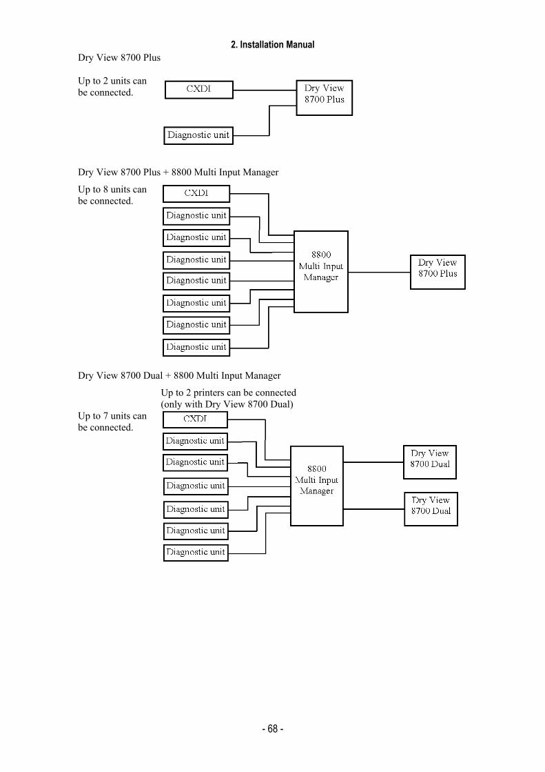
2. Installation Manual
- 68 -
Dry View 8700 Plus Up to 2 units can be connected.
Dry View 8700 Plus + 8800 Multi Input Manager
Up to 8 units can be connected.
Dry View 8700 Dual + 8800 Multi Input Manager
Up to 2 printers can be connected (only with Dry View 8700 Dual)
Up to 7 units can be connected.
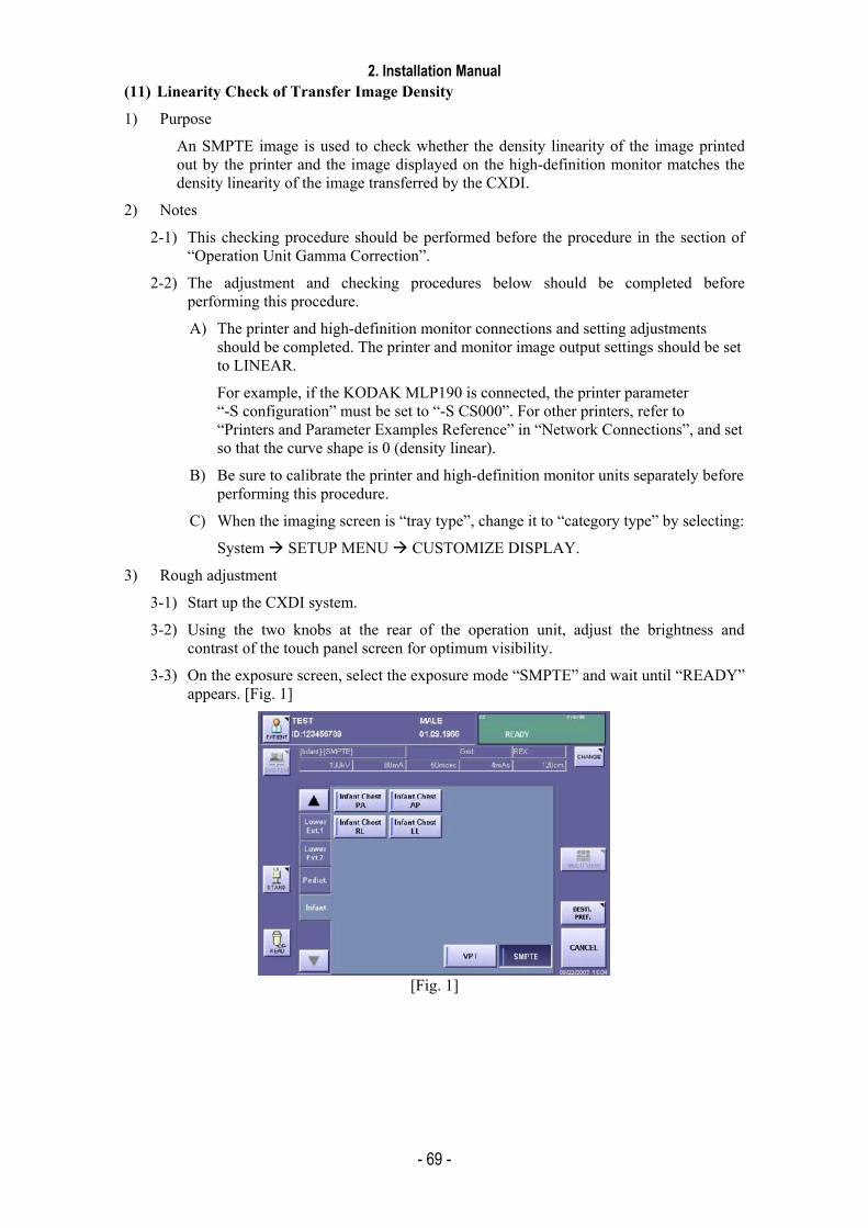
2. Installation Manual
- 69 -
(11) Linearity Check of Transfer Image Density
1) Purpose
An SMPTE image is used to check whether the density linearity of the image printed out by the printer and the image displayed on the high-definition monitor matches the density linearity of the image transferred by the CXDI.
2) Notes
2-1) This checking procedure should be performed before the procedure in the section of “Operation Unit Gamma Correction”.
2-2) The adjustment and checking procedures below should be completed before performing this procedure.
A) The printer and high-definition monitor connections and setting adjustments should be completed. The printer and monitor image output settings should be set to LINEAR.
For example, if the KODAK MLP190 is connected, the printer parameter “-S configuration” must be set to “-S CS000”. For other printers, refer to “Printers and Parameter Examples Reference” in “Network Connections”, and set so that the curve shape is 0 (density linear).
B) Be sure to calibrate the printer and high-definition monitor units separately before performing this procedure.
C) When the imaging screen is “tray type”, change it to “category type” by selecting:
System SETUP MENU CUSTOMIZE DISPLAY.
3) Rough adjustment
3-1) Start up the CXDI system.
3-2) Using the two knobs at the rear of the operation unit, adjust the brightness and contrast of the touch panel screen for optimum visibility.
3-3) On the exposure screen, select the exposure mode “SMPTE” and wait until “READY” appears. [Fig. 1]
[Fig. 1]
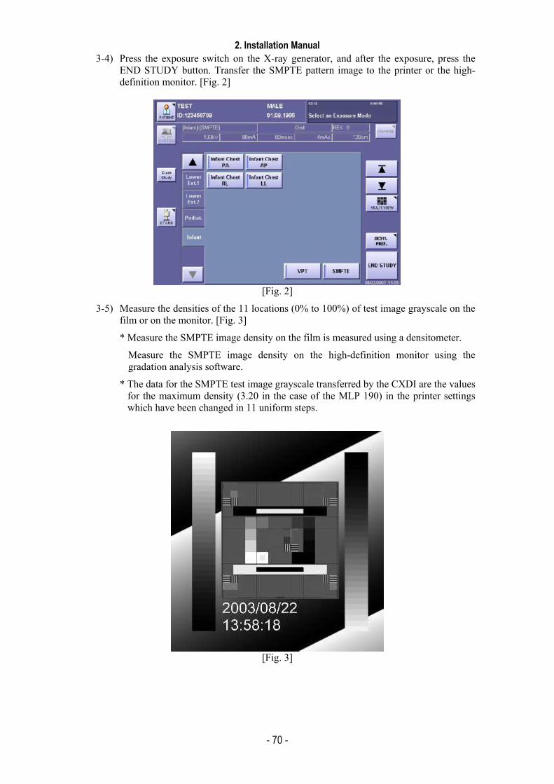
2. Installation Manual
- 70 -
3-4) Press the exposure switch on the X-ray generator, and after the exposure, press the END STUDY button. Transfer the SMPTE pattern image to the printer or the high-definition monitor. [Fig. 2]
[Fig. 2]
3-5) Measure the densities of the 11 locations (0% to 100%) of test image grayscale on the film or on the monitor. [Fig. 3]
* Measure the SMPTE image density on the film is measured using a densitometer.
Measure the SMPTE image density on the high-definition monitor using the gradation analysis software.
* The data for the SMPTE test image grayscale transferred by the CXDI are the values for the maximum density (3.20 in the case of the MLP 190) in the printer settings which have been changed in 11 uniform steps.
[Fig. 3]

2. Installation Manual
- 71 -
3-6) Create the graph below based on the data measured in step 5).
0.000.501.001.502.002.503.003.50
1 2 3 4 5 6 7 8 9 10 11Step
Den
sity
As shown in the above graph, the measurement values need only to nearly form a straight line from the minimum density to the maximum density.
The important point here is that the measurement values make a straight line and a maximum density corresponding to the settings is output.
If the measurement values deviate too far from the straight line and a maximum density corresponding to the settings is not output, printer and monitor output linearity settings, calibration, and other adjustments are necessary.
* The above graph is an example of measurements when the maximum density is set to 3.2 D and the printed film is measured with a densitometer. Refer to the data below when the maximum density is set to 3.1 D, or when gradation analysis software is used to take measurements on the monitor.
* The LINEAR output cannot be set for some printer models.
In this case, try to select an output setting as close as possible to LINEAR.
Ideal density values in LINEAR LINE Step 1 2 3 4 5 6 7 8 9 10 11
3.2 D 0 0.32 0.64 0.96 1.28 1.60 1.92 2.24 2.56 2.88 3.20 3.1 D 0 0.31 0.62 0.93 1.24 1.55 1.86 2.17 2.48 2.79 3.10 12 Bit 0 410 819 1229 1638 2048 2457 2867 3276 3686 4095 8 Bit 0 26 51 77 102 128 153 179 204 230 255
Possible causes of non-linearity in measurement values:
* Inadequate calibration of printer and high-definition monitor
* Inadequate settings for CXDI printer parameters
* Faults in printer or high-definition monitor
Max setting density
Film base density
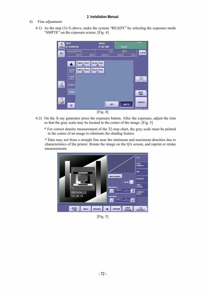
2. Installation Manual
- 72 -
4) Fine adjustment
4-1) As the step (3)-3) above, make the system “READY” by selecting the exposure mode “SMPTE” on the exposure screen. [Fig. 4]
[Fig. 4]
4-2) On the X-ray generator press the exposure button. After the exposure, adjust the trim so that the gray scale may be located in the center of the image. [Fig. 5]
* For correct density measurement of the 32-step chart, the gray scale must be printed in the center of an image to eliminate the shading feature.
* Data may not from a straight line near the minimum and maximum densities due to characteristics of the printer. Rotate the image on the QA screen, and reprint or retake measurements.
[Fig. 5]

2. Installation Manual
- 73 -
4-3) Select the END STUDY and transfer the SMPTE pattern image to the printer or the high-definition monitor. [Fig. 6]
[Fig. 6]
4-4) On a printed film or on the monitor, measure the density of 32 steps of the grayscale on the test image. [Fig. 7]
*1: Measure the SMPTE image density on the film using a densitometer. The SMPTE image density on the high-definition monitor is measured using the gradation analysis software.
*2: The data for the SMPTE test image grayscale transferred by the CXDI are the values for the maximum density (3.20 in the case of the MLP 190) in the printer settings which have been changed into 32 uniform steps.
[Fig. 7]
Step1
Step32
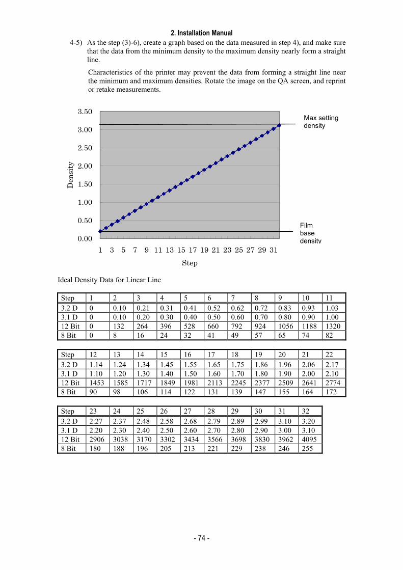
2. Installation Manual
- 74 -
4-5) As the step (3)-6), create a graph based on the data measured in step 4), and make sure that the data from the minimum density to the maximum density nearly form a straight line.
Characteristics of the printer may prevent the data from forming a straight line near the minimum and maximum densities. Rotate the image on the QA screen, and reprint or retake measurements.
0.00
0.50
1.00
1.50
2.00
2.50
3.00
3.50
1 3 5 7 9 11 13 15 17 19 21 23 25 27 29 31Step
Den
sity
Ideal Density Data for Linear Line Step 1 2 3 4 5 6 7 8 9 10 11 3.2 D 0 0.10 0.21 0.31 0.41 0.52 0.62 0.72 0.83 0.93 1.03 3.1 D 0 0.10 0.20 0.30 0.40 0.50 0.60 0.70 0.80 0.90 1.00 12 Bit 0 132 264 396 528 660 792 924 1056 1188 13208 Bit 0 8 16 24 32 41 49 57 65 74 82
Step 12 13 14 15 16 17 18 19 20 21 22 3.2 D 1.14 1.24 1.34 1.45 1.55 1.65 1.75 1.86 1.96 2.06 2.17 3.1 D 1.10 1.20 1.30 1.40 1.50 1.60 1.70 1.80 1.90 2.00 2.10 12 Bit 1453 1585 1717 1849 1981 2113 2245 2377 2509 2641 27748 Bit 90 98 106 114 122 131 139 147 155 164 172
Step 23 24 25 26 27 28 29 30 31 32 3.2 D 2.27 2.37 2.48 2.58 2.68 2.79 2.89 2.99 3.10 3.20 3.1 D 2.20 2.30 2.40 2.50 2.60 2.70 2.80 2.90 3.00 3.10 12 Bit 2906 3038 3170 3302 3434 3566 3698 3830 3962 4095 8 Bit 180 188 196 205 213 221 229 238 246 255
Max setting density
Film base density

2. Installation Manual
- 75 -
<Reference 1>
In the data and graph below, the data was obtained by setting the Kodak MLP 190 to curve shape 0 (density linear), a maximum density of 3.20, the SMPTE test image was printed out, and the image data was measured.
As shown in the graph, the data from the minimum density (film base density) to the maximum density nearly form a straight line.
SMPTE Density Step 1 2 3 4 5 6 7 8 9 10 11 Percentage 0 10 20 30 40 50 60 70 80 90 100 Density (D) 0.17 0.46 0.75 1.03 1.36 1.66 1.98 2.29 2.59 2.90 3.20
0.00
0.50
1.00
1.50
2.00
2.50
3.00
3.50
1 2 3 4 5 6 7 8 9 10 11
Step
Den
sity
* The printer parameter settings in this case are:
-A 320 -T NO -M CUBIC -m NORMAL -S CS000
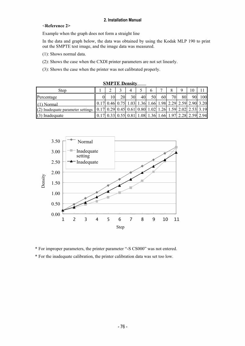
2. Installation Manual
- 76 -
<Reference 2>
Example when the graph does not form a straight line
In the data and graph below, the data was obtained by using the Kodak MLP 190 to print out the SMPTE test image, and the image data was measured.
(1): Shows normal data.
(2): Shows the case when the CXDI printer parameters are not set linearly.
(3): Shows the case when the printer was not calibrated properly.
SMPTE Density
Step 1 2 3 4 5 6 7 8 9 10 11Percentage 0 10 20 30 40 50 60 70 80 90 100
0.17 0.46 0.75 1.03 1.36 1.66 1.98 2.29 2.59 2.90 3.20(2) Inadequate parameter settings 0.17 0.29 0.45 0.61 0.80 1.02 1.26 1.59 2.02 2.53 3.19(3) Inadequate 0.17 0.33 0.55 0.81 1.08 1.36 1.66 1.97 2.28 2.59 2.94
(1) Normal
0.00
0.50
1.00
1.50
2.00
2.50
3.00
3.50
1 2 3 4 5 6 7 8 9 10 11 Step
Den
sity
Normal
Inadequate settingInadequate
* For improper parameters, the printer parameter “-S CS000” was not entered.
* For the inadequate calibration, the printer calibration data was set too low.
2. Installation Manual
- 77 -
(12) Operation Unit Gamma Correction
1) Purpose
This procedure is performed so that the image that is printed out or displayed on a high-definition monitor conforms exactly to the exposure image on the operation unit.
2) Notes
2-1) The procedure in “Linearity Check of Transfer Image Density” must be completed.
2-2) If image adjustment for the printer or high-definition monitor has not been made, use the “Gamma Correction Calculation Tool” in order to correct the gamma of high definition monitor image to be a same as printer image.
2-3) Gamma correction is an image correction process for monitors and film. It is different from the contrast setting or grayscale setting.
This procedure is simply a visual adjustment. As a result, differences may occur depending on the operator performing the procedure. Therefore, be sure to consult with the responsible technician before performing this adjustment.
2-4) To make the gamma of operation unit adjust in detail, use the “Gamma Correction Calculation Tool”.
3) Preparation
The Option button used in gamma correction is normally hidden. Edit the MenuPara.ini file to display.
3-1) Open MenuPara.ini file.
3-2) Make the following changes, and overwrite the file.
Use Search in Edit to find OptionDlgBth.
Select Customize.
OptionDlgBtn = 0 Change to 1.
(0: Don’t display; 1: Display)

2. Installation Manual
- 78 -
4) Comparison of operation unit image and print image or monitor image.
4-1) Start up the CXDI system.
4-2) Use the two adjustment knobs at the rear of the operation unit to adjust the brightness and contrast of the touch panel screen for optimum visibility.
4-3) On the exposure screen, select the exposure mode “SMPTE” and wait until “READY” appears. [Fig. 1].
[Fig. 1]
4-4) On the X-ray generator, press the exposure button, and after the exposure, select “END STUDY”. Transfer the SMPTE pattern image to the printer or the high-definition monitor. [Fig. 2]
[Fig. 2]
4-5) Take the SMPTE pattern image again. On the QA screen, compare the image displayed on the operation unit screen with the film image printed in Step 4) above or with the image on the high-definition monitor. Make sure there is no difference in contrast and gradation between those images. Check both preview and magnify images.
If there are any differences between these images, perform the procedure described in “(4) Operation Unit Image Gamma Correction” on the next page.
If there are no differences between these images, the steps are complete.

2. Installation Manual
- 79 -
5) Operation Unit Image Gamma Correction
5-1) On the QA screen displayed on Step (4) 5) above, select the “Option” tab and the “Gamma Adjustment” button is appeared, and then press this button. [Fig. 3]
[Fig. 3]
5-2) The “Gamma Adjustment’ window appears. Change the value for the PREVIEW IMAGE, and press OK. The gamma correction for the operation unit screen is performed. [Fig. 4]
(Make sure the gamma value for the test image has changed on the operation unit screen.)
The gamma value is adjustable from 1.00 to 2.50.
When the image on the operation unit is lighter (whiter) than the film image, increase the value. On the contrary, if the image on the operation unit is darker (blacker) than the film image, decrease the value. The default gamma value is 1.60.
[Fig. 4]
5-3) When the gamma value for the preview image is adjusted, then adjust the gamma value for the magnify image. The default gamma value for the magnify image is 1.60.
5-4) The correction steps are complete.
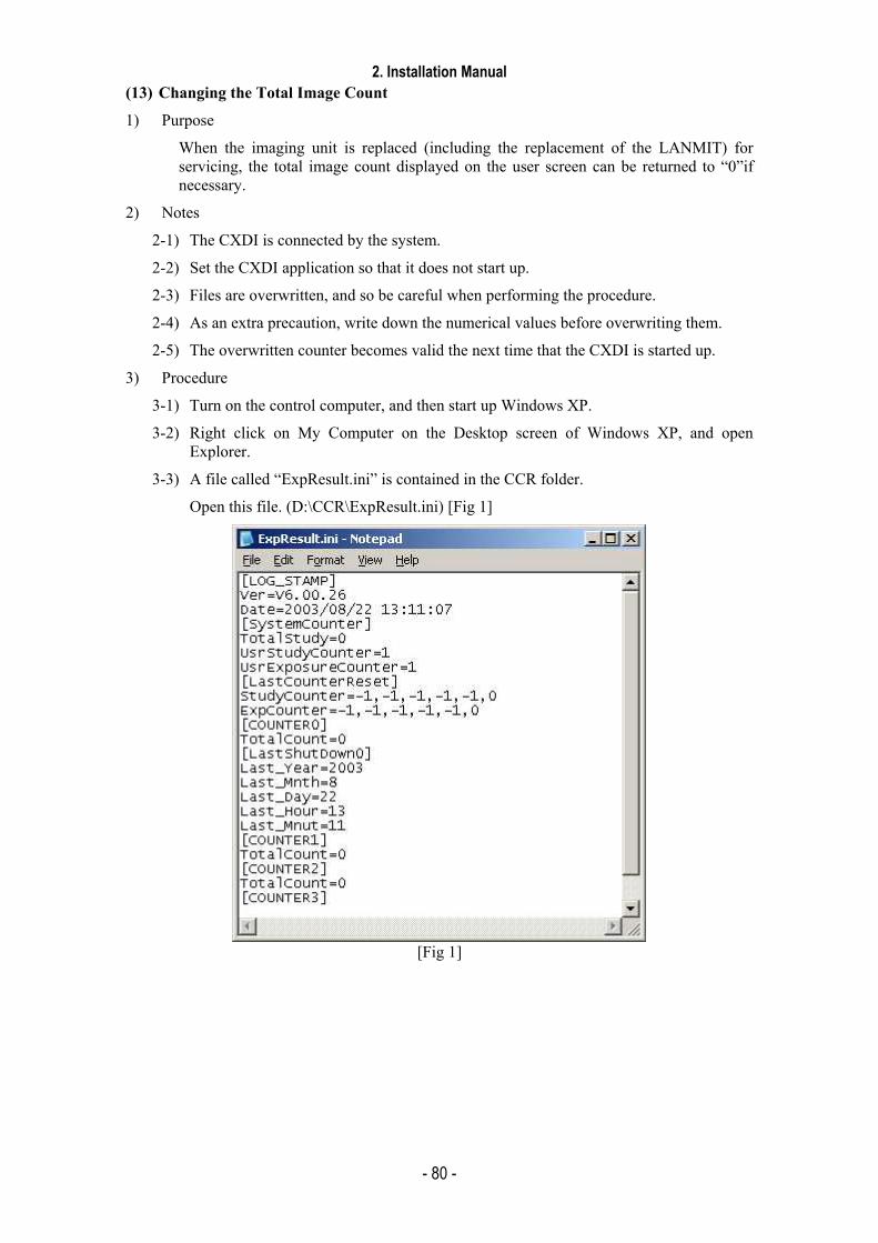
2. Installation Manual
- 80 -
(13) Changing the Total Image Count
1) Purpose
When the imaging unit is replaced (including the replacement of the LANMIT) for servicing, the total image count displayed on the user screen can be returned to “0”if necessary.
2) Notes
2-1) The CXDI is connected by the system.
2-2) Set the CXDI application so that it does not start up.
2-3) Files are overwritten, and so be careful when performing the procedure.
2-4) As an extra precaution, write down the numerical values before overwriting them.
2-5) The overwritten counter becomes valid the next time that the CXDI is started up.
3) Procedure
3-1) Turn on the control computer, and then start up Windows XP.
3-2) Right click on My Computer on the Desktop screen of Windows XP, and open Explorer.
3-3) A file called “ExpResult.ini” is contained in the CCR folder.
Open this file. (D:\CCR\ExpResult.ini) [Fig 1]
[Fig 1]

2. Installation Manual
- 81 -
3-4) Changing the items below contained in the file allows you to change the settings for the counter in the user screen.
ExpResult.ini file Screen Display Note [SystemCounter] TotalStudy= TOTAL STUDIES
UsrStudyCounter= STUDY COUNTER Can be overwritten at the user screen
UsrExposure Counter= IMAGE COUNTER Can be overwritten at the
user screen [LastCounterReset] StudyCounter= Year, month, day, hour, minute ExpCounter= Year, month, day, hour, minute [COUNTER 0]
TotalCount= Total number of images obtained with sensor unit 1.
[COUNTER1]
TotalCount= Total number of images obtained with sensor unit 2.
[COUNTER2]
TotalCount= Total number of images obtained with sensor unit 3.
[COUNTER3]
TotalCount= Total number of images obtained with sensor unit 4.
3-5) After overwriting the values, overwrite the file “ExpResult.ini” and save.
3-6) Close all windows that are open on the Desktop, and then start up the CXDI application.
3-7) Open the “System Information” screen, and check that the changed items have been set correctly. [Fig 2]
“TOTAL IMAGES” indicates the total number of images obtained with all sensors automatically.
[Fig 2]
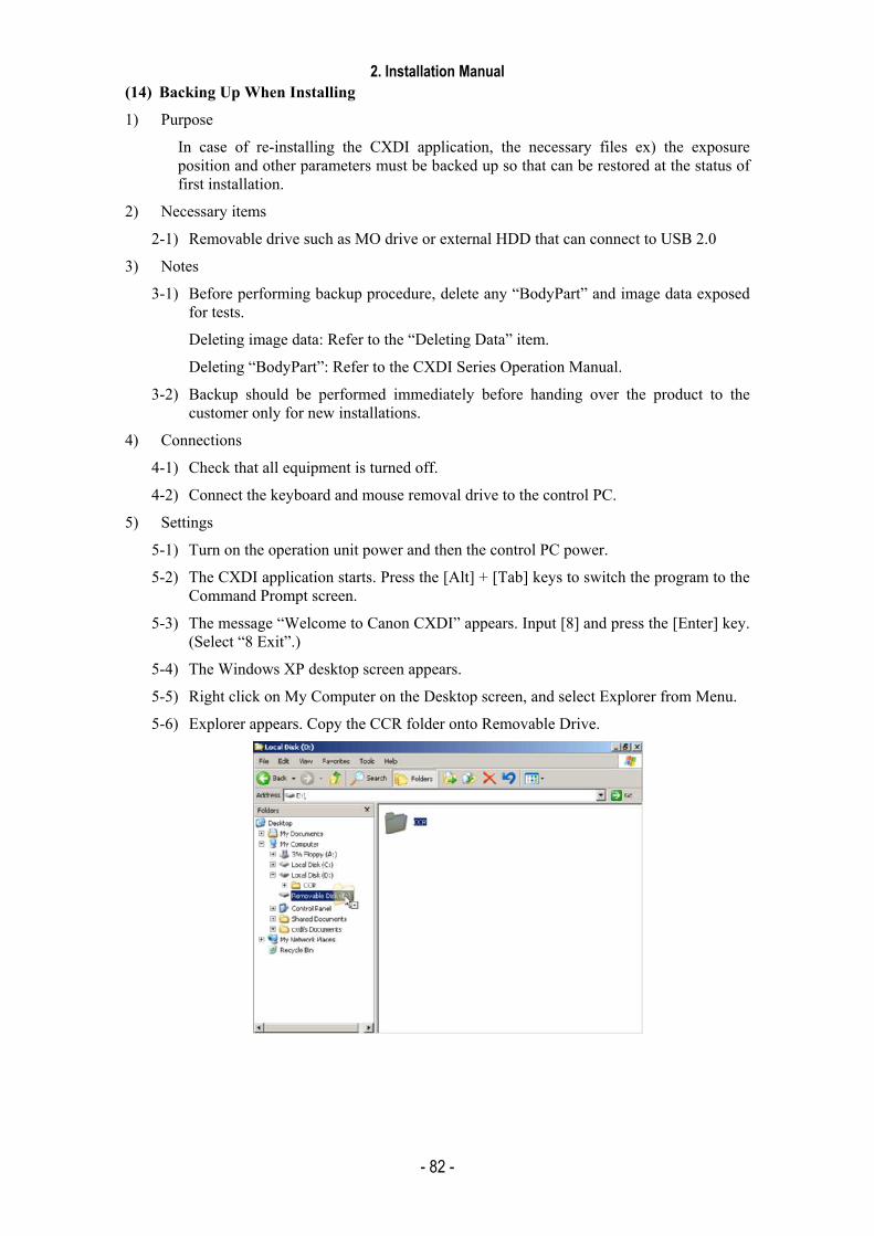
2. Installation Manual
- 82 -
(14) Backing Up When Installing
1) Purpose
In case of re-installing the CXDI application, the necessary files ex) the exposure position and other parameters must be backed up so that can be restored at the status of first installation.
2) Necessary items
2-1) Removable drive such as MO drive or external HDD that can connect to USB 2.0
3) Notes
3-1) Before performing backup procedure, delete any “BodyPart” and image data exposed for tests.
Deleting image data: Refer to the “Deleting Data” item.
Deleting “BodyPart”: Refer to the CXDI Series Operation Manual.
3-2) Backup should be performed immediately before handing over the product to the customer only for new installations.
4) Connections
4-1) Check that all equipment is turned off.
4-2) Connect the keyboard and mouse removal drive to the control PC.
5) Settings
5-1) Turn on the operation unit power and then the control PC power.
5-2) The CXDI application starts. Press the [Alt] + [Tab] keys to switch the program to the Command Prompt screen.
5-3) The message “Welcome to Canon CXDI” appears. Input [8] and press the [Enter] key. (Select “8 Exit”.)
5-4) The Windows XP desktop screen appears.
5-5) Right click on My Computer on the Desktop screen, and select Explorer from Menu.
5-6) Explorer appears. Copy the CCR folder onto Removable Drive.
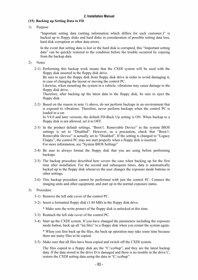
2. Installation Manual
- 83 -
(15) Backing up Setting Data to FD
1) Purpose
“Important setting data (setting information which differs for each customer.)” is backed up to floppy disks and hard disks in consideration of possible setting data loss, hard disk corruption or other data errors.
In the event that setting data is lost or the hard disk is corrupted, this “Important setting data” can be quickly restored to the condition before the trouble occurred by copying from the backup data.
2) Notes
2-1) Performing this backup work means that the CXDI system will be used with the floppy disk inserted in the floppy disk drive. Be sure to eject the floppy disk from floppy disk drive in order to avoid damaging it, in case of changing the layout or moving the control PC. Likewise, when mounting the system in a vehicle, vibrations may cause damage to the floppy disk drive. Therefore, after backing up the latest data to the floppy disk, be sure to eject the floppy disk.
2-2) Based on the reason in note 1) above, do not perform backups in an environment that is exposed to vibrations. Therefore, never perform backups when the control PC is loaded in a car. In V4.0 and later versions, the default FD-Buck Up setting is ON. When backup to a floppy disk is not allowed, set it to OFF.
2-3) In the product default settings, “Boot/1. Removable Device” in the system BIOS settings is set to “Disabled”. However, as a precaution, check that “Boot/1. Removable Device” is actually set to “Disabled”. If the setting is changed to “Legacy Floppy”, the control PC may not start properly when a floppy disk is inserted. For more information, see “System BIOS Settings”
2-4) Be sure to always format the floppy disk that you are using before performing backups.
2-5) The backup procedure described here covers the case when backing up for the first time after installation. For the second and subsequent times, data is automatically backed up to the floppy disk whenever the user changes the exposure mode buttons or other settings.
2-6) This backup procedure cannot be performed with just the control PC. Connect the imaging units and other equipment, and start up in the normal exposure status.
3) Procedure
3-1) Remove the left side cover of the control PC.
3-2) Insert a formatted floppy disk (1.44 MB) in the floppy disk drive.
* Make sure the write protect of the floppy disk is unlocked at this time.
3-3) Reattach the left side cover of the control PC.
3-4) Start up the CXDI system. If you have changed the parameters including the exposure mode button, back up all “ini.files” to a floppy disk when you restart the system again.
* When you first back up the files, the back up operation may take some time because there are many files to be copied.
3-5) Make sure that all files have been copied and switch off the CXDI system.
The files copied to a floppy disk are the “C:\ccrbup”, and they are the latest backup data. If the data stored in the drive D is damaged and there is no trouble in the drive C, restore the CXDI setting data using the data in “C:\ccrbup”.

2. Installation Manual
- 84 -
(16) Tool Modes (/np mode)
1) Purpose
The tool modes (startup options) are intended in order to check operation, and are used to launch the CXDI application on the control PC by itself, and to display items that are not normally displayed.
2) Notes
The following operation must be performed before using the “/np” mode. Especially, be sure to back up the exposure mode names and the customized settings before the operation.
2-1) When using “/np” with the same settings as that of the connected sensor unit
“BodyPart**.ini” file can be used as it is.
Example:
Connection /np setting Sensor1 Table Table Sensor2 Stand Stand
2-2) In case of using “/np” with different settings from that of the connected sensor unit
Move the “BodyPart**.ini” file in the “BodyParts” folder to the desktop, etc. However, do not move the Reference folder. If the “BodyPart**.ini” file is left in the “BodyParts” folder, system will not be able to be started, as the sensor type of the “BodyPart” and the settings do not match. Example:
Connection /np setting Sensor1 Table Table Sensor2 Stand Stand
3) Preparation
3-1) Connect the keyboard and the mouse to the control PC.
3-2) Delete the “ccrstart.bat” file from startup.
3-3) Disconnect the imaging unit from the control PC.
4) Startup method
4-1) Start up Windows XP.
4-2) Start the Command Prompt screen.
Start ⇒ Program ⇒ Accessories ⇒ Command Prompt
4-3) Command Prompt screen appears, type the commands following instruction below to start the CXDI application. (Press the [Enter] key after typing the command.)
No. Command Prompt Command Note. 1 C:\> D:
2 D:\> cd ccr “Space” delimiter is required between “cd” and “ccr”.
3 D:\ccr> ccrxxxxx /np “Space” delimiter is required between “xxxxx” and “/”. “xxxxx” is different in version.
4-4) If the message “Sensor not connected” appears at starting of the CXDI application,
click [OK] button, Change to the “Debugging mode” with the keys ([Alt] + [Tab]) using.
4-5) When Welcome to CCR appears, select “1. Set-Up...”.
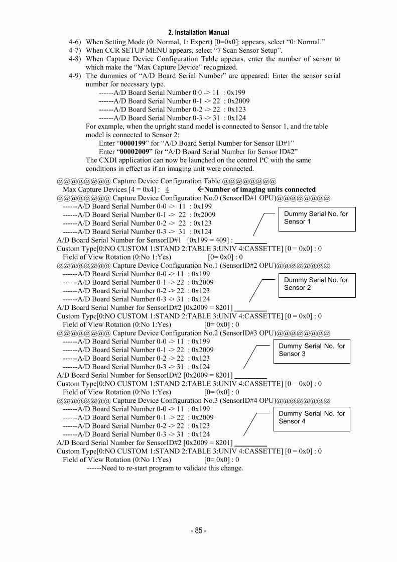
2. Installation Manual
- 85 -
4-6) When Setting Mode (0: Normal, 1: Expert) [0=0x0]: appears, select “0: Normal.” 4-7) When CCR SETUP MENU appears, select “7 Scan Sensor Setup”. 4-8) When Capture Device Configuration Table appears, enter the number of sensor to
which make the “Max Capture Device” recognized. 4-9) The dummies of “A/D Board Serial Number” are appeared: Enter the sensor serial
number for necessary type. ------A/D Board Serial Number 0 0 -> 11 : 0x199 ------A/D Board Serial Number 0-1 -> 22 : 0x2009 ------A/D Board Serial Number 0-2 -> 22 : 0x123 ------A/D Board Serial Number 0-3 -> 31 : 0x124
For example, when the upright stand model is connected to Sensor 1, and the table model is connected to Sensor 2:
Enter “0000199” for “A/D Board Serial Number for Sensor ID#1” Enter “00002009” for “A/D Board Serial Number for Sensor ID#2”
The CXDI application can now be launched on the control PC with the same conditions in effect as if an imaging unit were connected.
@@@@@@@@ Capture Device Configuration Table @@@@@@@@ Max Capture Devices [4 = 0x4] : 4 Number of imaging units connected
@@@@@@@@ Capture Device Configuration No.0 (SensorID#1 OPU)@@@@@@@@ ------A/D Board Serial Number 0-0 -> 11 : 0x199 ------A/D Board Serial Number 0-1 -> 22 : 0x2009 ------A/D Board Serial Number 0-2 -> 22 : 0x123 ------A/D Board Serial Number 0-3 -> 31 : 0x124
A/D Board Serial Number for SensorID#1 [0x199 = 409] : Custom Type[0:NO CUSTOM 1:STAND 2:TABLE 3:UNIV 4:CASSETTE] [0 = 0x0] : 0
Field of View Rotation (0:No 1:Yes) [0= 0x0] : 0 @@@@@@@@ Capture Device Configuration No.1 (SensorID#2 OPU)@@@@@@@@
------A/D Board Serial Number 0-0 -> 11 : 0x199 ------A/D Board Serial Number 0-1 -> 22 : 0x2009 ------A/D Board Serial Number 0-2 -> 22 : 0x123 ------A/D Board Serial Number 0-3 -> 31 : 0x124
A/D Board Serial Number for SensorID#2 [0x2009 = 8201] Custom Type[0:NO CUSTOM 1:STAND 2:TABLE 3:UNIV 4:CASSETTE] [0 = 0x0] : 0
Field of View Rotation (0:No 1:Yes) [0= 0x0] : 0 @@@@@@@@ Capture Device Configuration No.2 (SensorID#3 OPU)@@@@@@@@
------A/D Board Serial Number 0-0 -> 11 : 0x199 ------A/D Board Serial Number 0-1 -> 22 : 0x2009 ------A/D Board Serial Number 0-2 -> 22 : 0x123 ------A/D Board Serial Number 0-3 -> 31 : 0x124
A/D Board Serial Number for SensorID#2 [0x2009 = 8201] Custom Type[0:NO CUSTOM 1:STAND 2:TABLE 3:UNIV 4:CASSETTE] [0 = 0x0] : 0
Field of View Rotation (0:No 1:Yes) [0= 0x0] : 0 @@@@@@@@ Capture Device Configuration No.3 (SensorID#4 OPU)@@@@@@@@
------A/D Board Serial Number 0-0 -> 11 : 0x199 ------A/D Board Serial Number 0-1 -> 22 : 0x2009 ------A/D Board Serial Number 0-2 -> 22 : 0x123 ------A/D Board Serial Number 0-3 -> 31 : 0x124
A/D Board Serial Number for SensorID#2 [0x2009 = 8201] Custom Type[0:NO CUSTOM 1:STAND 2:TABLE 3:UNIV 4:CASSETTE] [0 = 0x0] : 0
Field of View Rotation (0:No 1:Yes) [0= 0x0] : 0 ------Need to re-start program to validate this change.
Dummy Serial No. for Sensor 1
Dummy Serial No. for Sensor 2
Dummy Serial No. forSensor 3
Dummy Serial No. forSensor 4

2. Installation Manual
- 86 -
4-10)When CCR SETUP MENU appears, press the [Esc] key to return to Welcome to CCR.
4-11) Select the command “8 - Exit” in the “Welcome to CCR” menu to exit the CXDI application.
4-12) After exit the CXDI application and Windows XP desktop appears, starts the command prompt screen (Start ⇒ Program ⇒ Command Prompt). And type the command “ccrxxxxx /np” to start the CXDI application again.
a. When the CXDI application program is starting up, the message “There is no BodyPart for SensorID#*. ** TYPE BodyPart will be created” appears. Click [OK]. (* differs according to the type of the sensor.)
The above message appears when a /np mode is used with a setting different to that of the connected sensor.
b. The messages “Conflicting X-ray parameters. Do you wish to reset parameters?” and “Conflicting X-ray tube parameters for each imaging method. Do you wish to reset parameters” appear. Click [OK] for each.
These above messages might be appeared if /np mode is used with a different setting.
5) Going out of /np mode
Connect the sensor unit to the control PC.
Before using the system in normal condition, perform the following steps:
5-1) If /np mode has been used with a different setting as that of the connected sensor, as mentioned in “(3) Notes”, delete the BodyPart**.ini file made in the BodyParts folder, and return the BodyPart**.ini file which has been moved into the BodyParts folder.
5-2) Enter the command “ccrstart.bat” on command prompt to boot the CXDI application.
Follow the procedure from 3) to 9) in previous section. And check these one will be preformed properly without any problems.
5-3) Register the ccrstart.bat file to the StartUp.

2. Installation Manual
- 87 -
5.8 Adjusting the Alignment
1. Outline Align the center of the sensor unit with the center of the X-ray tube. Be sure that the crossing angle is perpendicular. * Alignment of the sensor should be performed based on the assumption that the X-ray generator is
set in the correct horizontal and vertical position. If the X-ray generator is displaced to a large extent, the alignment of the sensor may not compensate the misalignment of the X-ray generator. In this case, you need to ask the manufacturer of X-ray generator to align the position of the X-ray generator again.
* If the table type is used, align the sensor unit before mounting a top panel. * If anchoring is required for the stand or the table you are going to install, be careful not to disturb
the alignment. For details of anchoring, please refer to the Service Manuals of stand type. 2. Tools (should be prepared by distributors) Alignment Adjustment Spacer, Mirror (first-face mirror), Tape, Oil-based Marker, Measure, Rope, and other requirements. 3. Adjustment 3.1 Stand (1) Fix the mirror (first-face mirror) at the center of the sensor unit. (2) Place the stand temporarily in the position to space enough distance for the exposure.
Distance from the tube to the sensor unit should be 180cm. Using a measure or rope, align the horizontal position of the sensor unit to the center of the
tube so that the distance from the tube to the right and left side of the sensor is symmetric.
[Top View]
Fix the mirror
x
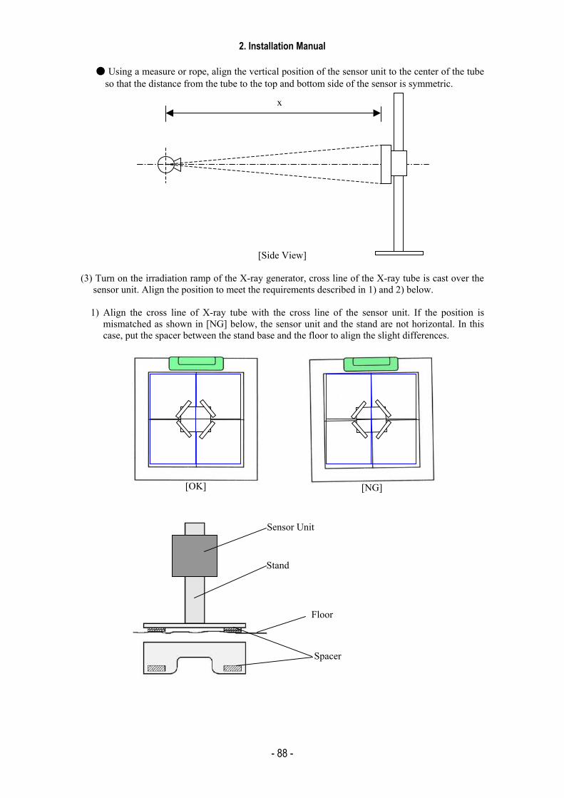
2. Installation Manual
- 88 -
Using a measure or rope, align the vertical position of the sensor unit to the center of the tube
so that the distance from the tube to the top and bottom side of the sensor is symmetric.
[Side View] (3) Turn on the irradiation ramp of the X-ray generator, cross line of the X-ray tube is cast over the
sensor unit. Align the position to meet the requirements described in 1) and 2) below.
1) Align the cross line of X-ray tube with the cross line of the sensor unit. If the position is mismatched as shown in [NG] below, the sensor unit and the stand are not horizontal. In this case, put the spacer between the stand base and the floor to align the slight differences.
[OK]
Sensor Unit
Stand
Floor
Spacer
[NG]
x
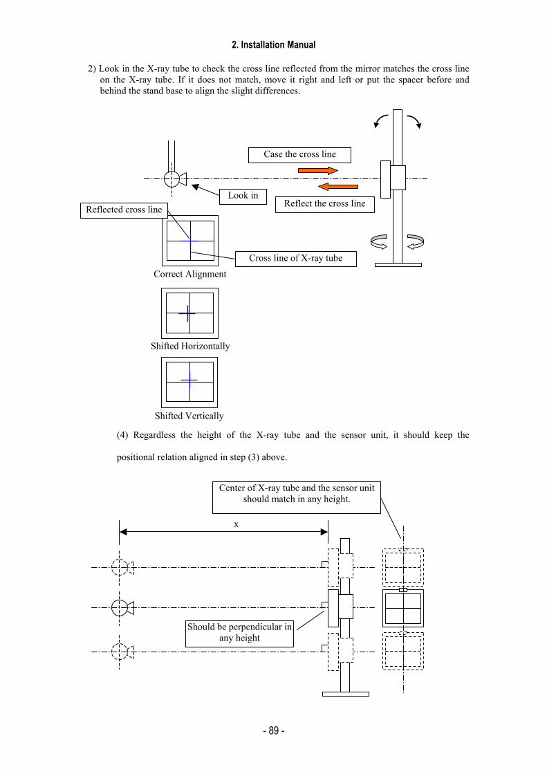
2. Installation Manual
- 89 -
2) Look in the X-ray tube to check the cross line reflected from the mirror matches the cross line
on the X-ray tube. If it does not match, move it right and left or put the spacer before and behind the stand base to align the slight differences.
(4) Regardless the height of the X-ray tube and the sensor unit, it should keep the
positional relation aligned in step (3) above.
x
Should be perpendicular in any height
Center of X-ray tube and the sensor unit should match in any height.
Case the cross line
Reflect the cross line
Correct Alignment
Shifted Horizontally
Shifted Vertically
Reflected cross line
Cross line of X-ray tube
Look in
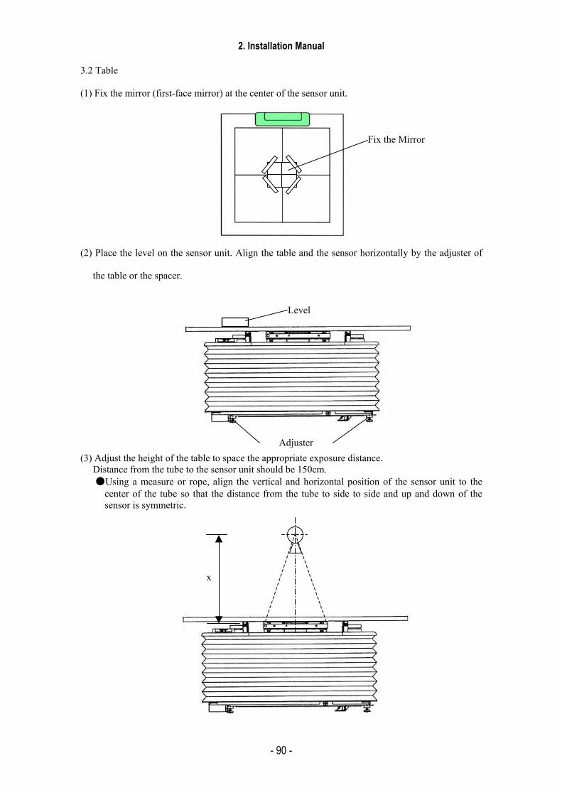
2. Installation Manual
- 90 -
3.2 Table (1) Fix the mirror (first-face mirror) at the center of the sensor unit. (2) Place the level on the sensor unit. Align the table and the sensor horizontally by the adjuster of
the table or the spacer.
(3) Adjust the height of the table to space the appropriate exposure distance.
Distance from the tube to the sensor unit should be 150cm. Using a measure or rope, align the vertical and horizontal position of the sensor unit to the
center of the tube so that the distance from the tube to side to side and up and down of the sensor is symmetric.
Fix the Mirror
Level
Adjuster
x
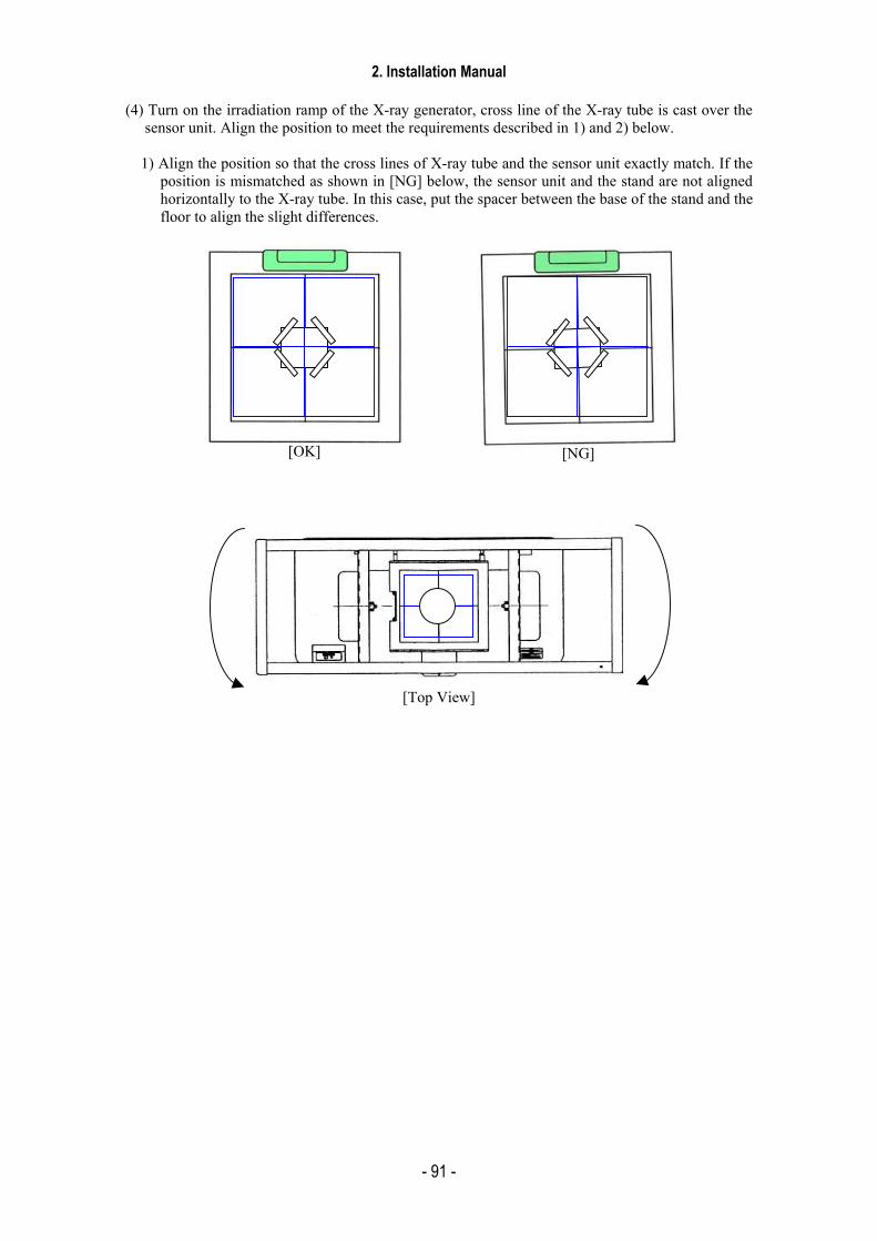
2. Installation Manual
- 91 -
(4) Turn on the irradiation ramp of the X-ray generator, cross line of the X-ray tube is cast over the
sensor unit. Align the position to meet the requirements described in 1) and 2) below.
1) Align the position so that the cross lines of X-ray tube and the sensor unit exactly match. If the position is mismatched as shown in [NG] below, the sensor unit and the stand are not aligned horizontally to the X-ray tube. In this case, put the spacer between the base of the stand and the floor to align the slight differences.
[Top View]
[OK] [NG]
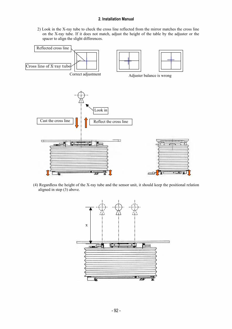
2. Installation Manual
- 92 -
2) Look in the X-ray tube to check the cross line reflected from the mirror matches the cross line
on the X-ray tube. If it does not match, adjust the height of the table by the adjuster or the spacer to align the slight differences.
(4) Regardless the height of the X-ray tube and the sensor unit, it should keep the positional relation
aligned in step (3) above.
Correct adjustment Adjuster balance is wrong
Reflected cross line
Cross line of X-ray tube
x
Cast the cross line Reflect the cross line
Look in

2. Installation Manual
- 93 -
5.9 Image Quality (1) Purpose
This procedure is used to check the final image quality of the CXDI.
1) Resolution check
Tools used
(1) Phantom
(2) High-resolution monitor or DICOM printer
Procedure
Procedure/Item Operation/Conditions
1. Adjust the distance between the focal point of the X-ray tube and the CXDI sensor unit. X cm: Differs according to the grid being used. 2. Perform calibration
SYSTEM > CALIBRATION 3. Perform self-test.
SYSTEM > SELF TEST Must pass all the tests.
X-ray tube focal point
X cm
Right angle at the center
CXDI Sensor Unit
Self-test
[Positioning]
Position the X-ray tube and CXDI Sensor Unit
Calibration
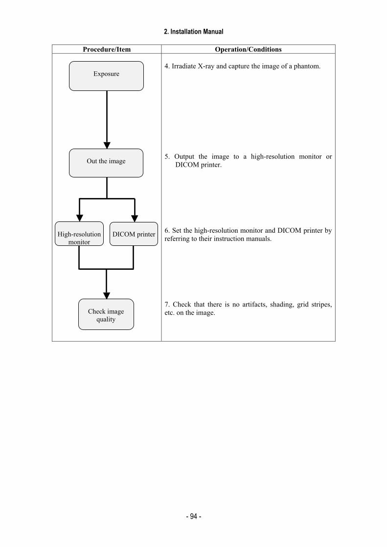
2. Installation Manual
- 94 -
Procedure/Item Operation/Conditions
4. Irradiate X-ray and capture the image of a phantom. 5. Output the image to a high-resolution monitor or
DICOM printer. 6. Set the high-resolution monitor and DICOM printer by referring to their instruction manuals. 7. Check that there is no artifacts, shading, grid stripes, etc. on the image.
High-resolution
monitor
DICOM printer
Check image
quality
Exposure
Out the image
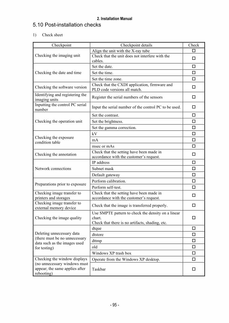
2. Installation Manual
- 95 -
5.10 Post-installation checks
1) Check sheet
Checkpoint Checkpoint details Check Align the unit with the X-ray tube
Checking the imaging unit Check that the unit does not interfere with the cables.
Set the date. Set the time. Checking the date and time Set the time zone.
Checking the software version Check that the CXDI application, firmware and PLD code versions all match.
Identifying and registering the imaging units Register the serial numbers of the sensors
Inputting the control PC serial number Input the serial number of the control PC to be used.
Set the contrast. Set the brightness. Checking the operation unit Set the gamma correction. kV mA Checking the exposure
condition table msec or mAs
Checking the annotation Check that the setting have been made in accordance with the customer’s request.
IP address Subnet mask Network connections Default gateway Perform calibration.
Preparations prior to exposure Perform self-test.
Checking image transfer to printers and storages
Check that the setting have been made in accordance with the customer’s request.
Checking image transfer to external memory device Check that the image is transferred properly.
Checking the image quality Use SMPTE pattern to check the density on a linear chart. Check that there is no artifacts, shading, etc.
dtque dtstore dttmp old
Deleting unnecessary data (there must be no unnecessary data such as the images used for testing)
Windows XP trash box Operate from the Windows XP desktop. Checking the window displays
(no unnecessary windows must appear; the same applies after rebooting)
Taskbar

2. Installation Manual
- 96 -
Checkpoint Checkpoint details Check
Inserting the backup floppy disk and checking the backup files
Create the backup files in floppy drive by re-starting. (Cannot be used in automobile)
Backing up ccr folder D:ccr Check that the CXDI application starts. Registering in startup.
(Check by rebooting) Check that no /d, /np or other flags have been raised.
Communication with X-ray generators kV, mA, msec, body part settings, etc.
[Table.1]
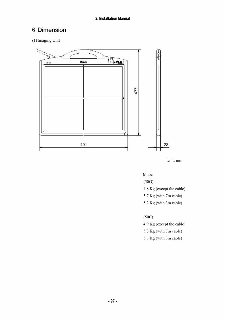
2. Installation Manual
- 97 -
66 DDiimmeennssiioonn (1) Imaging Unit
Unit: mm
Mass:
(50G)
4.8 Kg (except the cable)
5.7 Kg (with 7m cable)
5.2 Kg (with 3m cable)
(50C)
4.9 Kg (except the cable)
5.8 Kg (with 7m cable)
5.3 Kg (with 3m cable)

2. Installation Manual
- 98 -
(2) Power Box
Unit: mm
Mass: 4.2Kg

2. Installation Manual
- 99 -
(3) Remote Switch
Unit: mm
Mass: 0.5Kg
(4) Grid (Optional)
508 27
452
Unit: mm
Mass: 0.9Kg (Frame)
CCXXDDII--5500GG // 5500CC
CCaannoonn IInncc.. JJaappaann CCooppyyrriigghhtt ((CC)) CCaannoonn IInncc.. MMeeddiiccaall TTeecchhnniiccaall SSeerrvviiccee DDeepptt.. AAllll rriigghhttss RReesseerrvveedd..
33.. FFuunnccttiioonn
PPrriinntteedd bbyy CCaannoonn IInncc..MMaarr.. 22000077 RReevv..0044

Content
1 Imaging Unit.......................................................................................................................... 1
1.1 Block Diagram (Imaging Unit) ...................................................................................... 1
1.2 LANMIT UNIT ............................................................................................................. 2
1.3 PCB 50AD / PWB/50Di Block diagram........................................................................ 4
1.4 Imaging Unit .................................................................................................................. 5
2 Power Box ............................................................................................................................. 7
2.1 PWB-40 X-ray board ..................................................................................................... 7
2.2 Remote switch................................................................................................................ 7
2.3 50 Power supply............................................................................................................. 8
3 Available Imaging Time (Normal Imaging/Long-term Imaging) ......................................... 9
4 About the Power Box Initialization Switch ......................................................................... 13
5 How to Access to OS........................................................................................................... 14

3. Function
1
11 IImmaaggiinngg UUnniitt 1.1 Block Diagram (Imaging Unit) 1.1.1 CXDI-50G
1.1.2 CXDI-50C
Power Box
Power Box PC
B-50A
(2)
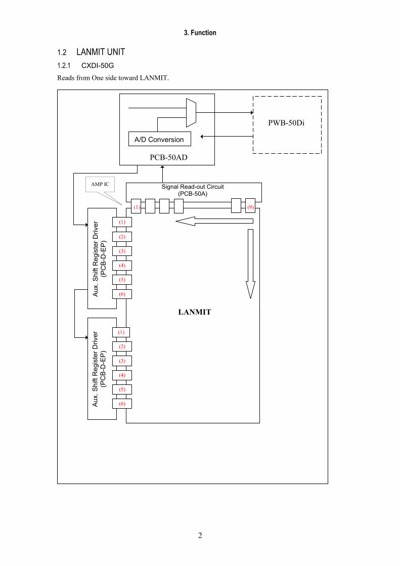
3. Function
2
1.2 LANMIT UNIT 1.2.1 CXDI-50G
Reads from One side toward LANMIT.
AMP IC
PCB-50AD
PWB-50Di
LANMIT
A/D Conversion
Signal Read-out Circuit (PCB-50A)
(1)
(2)
(3)
(4)
(5)
(6)
(1)
(2)
(3)
(4)
(5)
(6)
(9)
(1)
Aux
. Shi
ft R
egis
ter D
river
(P
CB
-D-E
P)
Aux
. Shi
ft R
egis
ter D
river
(P
CB
-D-E
P)
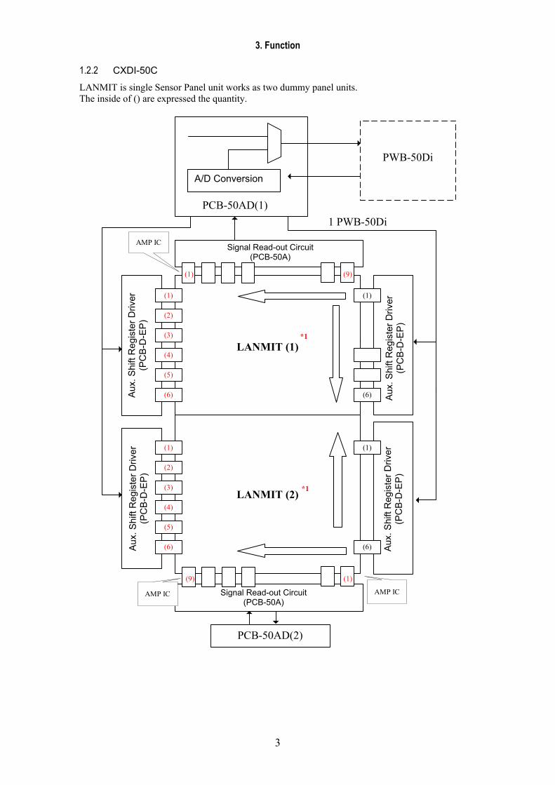
3. Function
3
1.2.2 CXDI-50C
LANMIT is single Sensor Panel unit works as two dummy panel units. The inside of () are expressed the quantity.
(1)
(6)
LANMIT (1)
LANMIT (2)
(1)
AMP IC
AMP IC AMP IC
(6)
PCB-50AD(2)
PCB-50AD(1)
PWB-50Di
1 PWB-50Di
A/D Conversion
Signal Read-out Circuit (PCB-50A)
(1)
(1)
(2)
(3)
(4)
(5)
(6)
(1)
(2)
(3)
(4)
(5)
(6)
(1)
*1
*1
(9)
(9)
Aux
. Shi
ft R
egis
ter D
river
(P
CB
-D-E
P)
Aux
. Shi
ft R
egis
ter D
river
(P
CB
-D-E
P)
Aux
. Shi
ft R
egis
ter D
river
(P
CB
-D-E
P)
Aux
. Shi
ft R
egis
ter D
river
(P
CB
-D-E
P)
Signal Read-out Circuit (PCB-50A)

3. Fu
nctio
n
4
1.3
PCB-
50AD
/ PW
B-50
Di B
lock D
iagra
m
PWB-
50D
i Im
agin
g un
it
32
PC
B-5
0AD
14
32
32
32
DA
TA B
US
MP
U
32
32
SD
RA
M
SD
RA
M
32
LAN
C
14
32
32
AD
OR
ES
S B
US
AD
MU
X o
utpu
t 10
.66M
Hz
Rea
dout
Med
iatin
g S
DR
AM
AC
CE
SS
from
MP
U
and
data
writ
ing
from
FIF
O.
Dat
a of
the
red
uced
-siz
e im
age
capt
ure
is
trans
ferre
d to
sy
stem
SD
RAM
by
D
MAC
in
M
PU.
Fram
e M
emor
y SD
RAM
IC
IC
IC
IC
IC
IC
IC
IC
Anal
og M
UX
128:
1 at
5.3
3MH
z
MU X
2:1
MU X
2:1
IC
IC
IC
IC
IC
IC
IC
IC
AD
C
AD
C
AD
C
AD
C
256
anal
og in
put
per I
C
IC
IC
MU X
2:1
MU X 2:1
MU X
2:1
MU X
2:1
14 14
SD
RA
M C
LOC
K 6
4MH
z
Pow
er B
ox
Con
trol P
C
PU
LSE
TR
AN
S
NIC
100B
aseT
X
14
14
14
14

3. Function
5
1.4 Imaging Unit The Imaging Unit’s function is listed below:
(1) Converts the acquired X-ray image to light signal using the fluorescent screen and stores.
(2) After reading the stored electric signal (Image) from the sensor, perform the A/D conversion and stores it on the frame memory temporally.
(3) Reduce the electric signal at the same time as storing and transfer it to the Control PC through the Power Box.
1.4.1 Sensor data file disks The data files unique to the sensor (LANMIT) are recorded on floppy disks. “Sensor data” refers to the sensitivity, deficiencies and other data unique to the sensor unit. The sensor data is recorded inside the sensor unit, and automatically downloaded to the control PC as sensor data files by the control software. 1.4.2 Sensor cable These cables are used to connect the CXDI-50G/50C Imaging unit and Power Box. -Communication line connected via the power box between the Imaging unit and Control PC. -Power line for supplying power from the Power box to the Imaging unit. -Communication line between the Imaging units - Power Box. 1.4.3 Grid unit This is the external fixed grid can attach and remove. The four types of grids in the table below are provided.
Grid ratio Convergence distance Grid density
1 10:1 180cm 40 LP/cm 2 8:1 110cm 40 LP/cm 3 6;1 150cm 40 LP/cm 4 4;1 110cm 40 LP/cm
3. Function
6
1.4.4 PWB-50Di board
The PWB-50Di board has the following functions:
(1) The sensor driving control. Reading the digital image signals outputted from the AD converter (PCB-50AD)
(2) The communication, the X-ray image transferring with the Control PC through the Power Box on the Ethernet.
(3) The synchronization between the X-ray generator and the image acquisition through the Power Box.
(4) The control of the LED displaying.
(5) Detecting the Grid by using the Grid detecting sensor.
(6) Relaying the power which Power Box supplies to the PCB-50AD.
(7) Detecting the unusual temperature, error reporting and stop the Sensor driving.
(8) Detecting the X-ray emission status.
(9) Holding the data factory set.
1.4.5 PCB-50 LED board
The PCB-50 LED board has the following functions.
(1) Power supply relaying (5.5V/3.3V/24V/-10V)
(2) LED control (POWER/READY/BUSY)
(3) The detecting Grid sensor connection.
(4) The case grounding around power supply.
(Each power supply cable must be put on the case grounding point with the screws.)

3. Function
7
22 PPoowweerr BBooxx
The Power Box consists of the following parts; PWB-40XRAY board (X-ray I/F), Power supply, Remote power switch. And it has the function that is the signal transition with Imaging Unit, Power supplying, the signal transition with the X-ray generator. The Power Box can be connected only one Imaging Unit.
2.1 PWB-40 X-ray board The PWB-40 X-ray board has the following function.
(1) The Interface with the X-ray generator.
(2) Relaying the signals insulating the Internet transition. (AC230V Basic Insulation)
(3) The cable length setting (3/7m) in the 50 Power supply capacity.
(4) The firm initializing code on the Imaging Unit boot switch is installed.
(5)
2.2 Remote switch (1) Output control of the 2nd side on the 50 Power supply (7m) or 50 Power supply (3m)
PWB-40XRAY

3. Function
8
2.3 50 Power supply (1) ACDC power supply Imaging Unit mainly use
Rated power supply (input) : AC 100 to 120V/AC 200 to 240V
Rated power supply (output) : CH1 9.5V, CH2 9.5V, CH3 6.8V, CH4 -11.5V, CH5 27V
(2) Added function
a) Over current protection: At detecting the over current, shutdown and reset is performed automatically
CH1, 2: Automatic current limiting over 105% of the PEAK Current (3.5A)
CH3: Shutdown over 200% of the NOMINAL Current (2.5A)
CH4: Automatic current limiting over 105% of the NOMINAL Current (0.2A)
CH5: Automatic current limiting at the Load Current (500mA)
* When the CH3 is shutdown, CH4 and CH5 is shutdown at the same time.
b) Over Voltage protection: When detecting the over voltage, shutdown the output.
Over 115% of the rated voltage
C) The switching (ON/OFF) of the 2nd side output voltage by using the remote ON/OFF controller is available
2nd side output display: LED (Green)

3. Function
9
33 AAvvaaiillaabbllee IImmaaggiinngg TTiimmee ((NNoorrmmaall IImmaaggiinngg//LLoonngg--tteerrmm IImmaaggiinngg)) [Overview] There are two available imaging times as follow:
1) Normal imaging (0 - 1000 msec)
2) Long-term imaging (1001 - 3000 msec)
From Version 6.0, the maximum imaging time is now 3 seconds for the CXDI-50G sensor, which can be set on the GUI.
[Precaution] • The preview display becomes slower when using long-term imaging. • The preview display may also become slower *1 when performing normal imaging using the
part button that is set to long-term imaging (imaging time settings: 1001 msec to 3000 msec). *1 The preview display becomes slower without the X-ray monitor, that is, when using the CXDI-50G/50C. (When an X-ray exposure negative cannot be detected, even if the X-ray monitor is used.)
• Imaging preparation time: 10 seconds for normal imaging and 30 seconds for long-term
imaging. In imaging preparation time, the imaging unit changes from sleep status (sensor in standby status) to ready status (possible to perform imaging).
(The imaging cycle time*2 becomes longer.)
*2 Time required preparing for the next imaging after a single imaging is done. Normal imaging: 15 sec, long-term imaging: 30 sec.
[Technical Description]
1. The maximum value for imaging condition
• When using the CXDI-50G/50C sensor, the maximum value of the exposure time is
3000 msec, which can be set on the screen. • The maximum value of the tube current is 1600 mA. - The maximum mAs value is
4800mAs due to the maximum value of the exposure time changing to 3000. The maximum value of the tube current is 1600mA. The maximum value of the mAs value is changed from the 3000 maximum value of the exposure time to 4800 mAs.
Exposure time Tube current mAs value
Up to CXDI V5.1 1000msec ↓
5000mA ↓
5000mAs ↓
CXDI-11- CXDI-31 sensor 1000msec 1600mA 1600mAs
CXDI-40G or later version sensor 3000msec 1600mA 4800mAs
Table 3-1
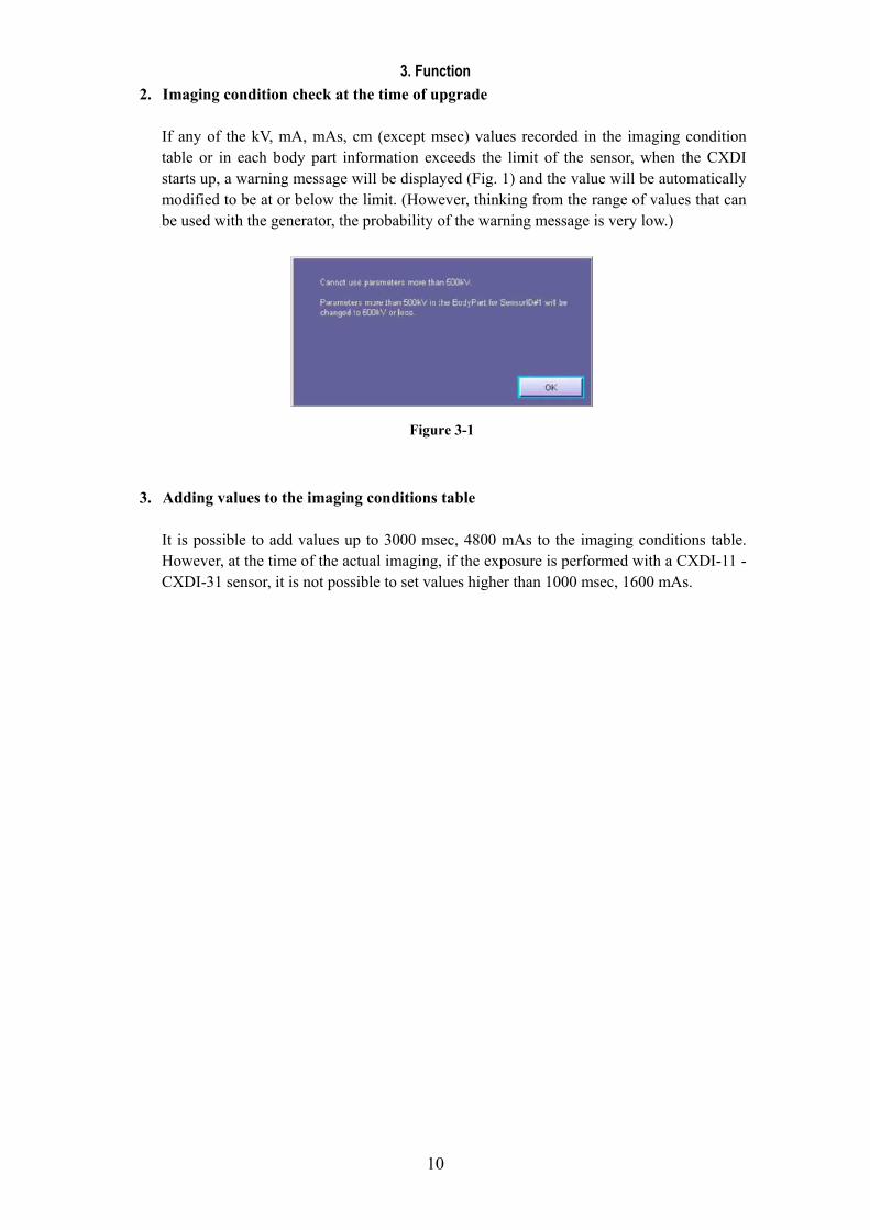
3. Function
10
2. Imaging condition check at the time of upgrade If any of the kV, mA, mAs, cm (except msec) values recorded in the imaging condition table or in each body part information exceeds the limit of the sensor, when the CXDI starts up, a warning message will be displayed (Fig. 1) and the value will be automatically modified to be at or below the limit. (However, thinking from the range of values that can be used with the generator, the probability of the warning message is very low.)
3. Adding values to the imaging conditions table
It is possible to add values up to 3000 msec, 4800 mAs to the imaging conditions table. However, at the time of the actual imaging, if the exposure is performed with a CXDI-11 - CXDI-31 sensor, it is not possible to set values higher than 1000 msec, 1600 mAs.
Figure 3-1
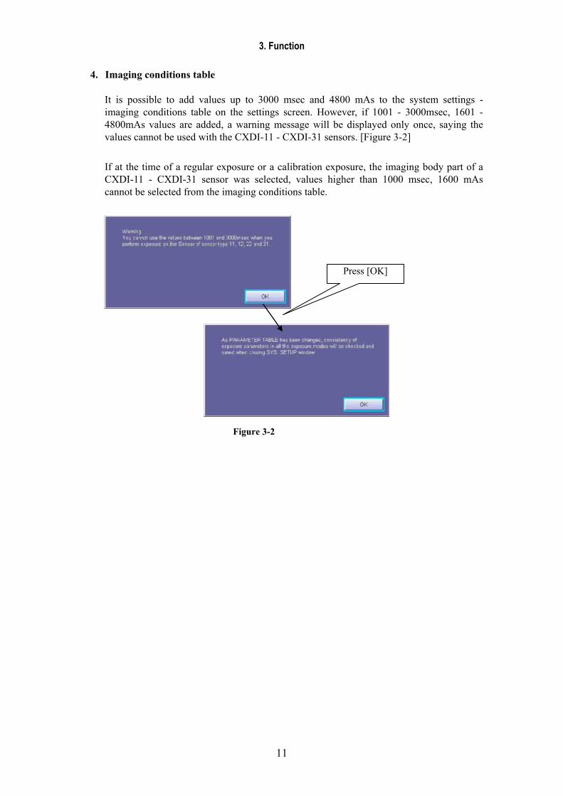
3. Function
11
4. Imaging conditions table
It is possible to add values up to 3000 msec and 4800 mAs to the system settings - imaging conditions table on the settings screen. However, if 1001 - 3000msec, 1601 - 4800mAs values are added, a warning message will be displayed only once, saying the values cannot be used with the CXDI-11 - CXDI-31 sensors. [Figure 3-2]
If at the time of a regular exposure or a calibration exposure, the imaging body part of a CXDI-11 - CXDI-31 sensor was selected, values higher than 1000 msec, 1600 mAs cannot be selected from the imaging conditions table.
Press [OK]
Figure 3-2
3. Function
12
5. msec maximum value checking
Even if the values recorded in the msec values of calibration/imaging body part within the BodyPart.ini exceed the maximum msec value of the sensor, the OPU can perform the exposure using those values without checking. (This function was already implemented before CXDI v5.1.) It is the same when using the msec imaging conditions table, if a value bigger than the sensor’s maximum msec value is written in the BodyPart.ini file, the value will not be automatically replaced with the value of the imaging conditions table, but can be used for the exposure as it is.
Note:
In the case of mAs lead, the msec will be automatically recalculated based on the mA, mAs, and the msec value will be automatically overwritten.
6. kV, mA, mAs, cm maximum value check
If any of the kV, mA, mAs, cm values of the calibration/imaging body part recorded within the BodyPart.ini file exceeds the maximum value of the sensor, when the CXDI starts up, a warning message will be displayed and the value will be automatically modified to be at or below the limit. (If the imaging conditions table is used, a table value not exceeding the maximum value of the sensor will be specified.)

3. Function
13
44 AAbboouutt tthhee PPoowweerr BBooxx IInniittiiaalliizzaattiioonn SSwwiittcchh Initialization Switch
The LAN can be started with the factory settings when you turn on the power (the main power of the power box and remote switch) by holding down the initialization switch (see figure *1) of the power box.
The 50G/50C firmware contains the initialization and normal codes.
(They are stored in the PWB-50Di flash ROM)
Normally, the normal code runs on a steady basis, and only normal code is updated when upgrading the firmware.
Use the initialization code when the normal code cannot start for some reason or when you have lost the Ethernet settings. Using the initialization code sets the Ethernet-related settings to the default settings and allows you to perform the startup operation for the initialization code.
In this case, the connection can be made by setting the Ethernet settings in the control PC to the 50G/50C default*2.
This default connection allows you to upgrade the firmware again and also check and set the Ethernet settings again in order to recover the system.
*1 Initialization Switch: Switch 1 mounted on PWB-40 XRY *2 Default settings: IP Address=192.168.100.11 (factory setting)
Initialization switch
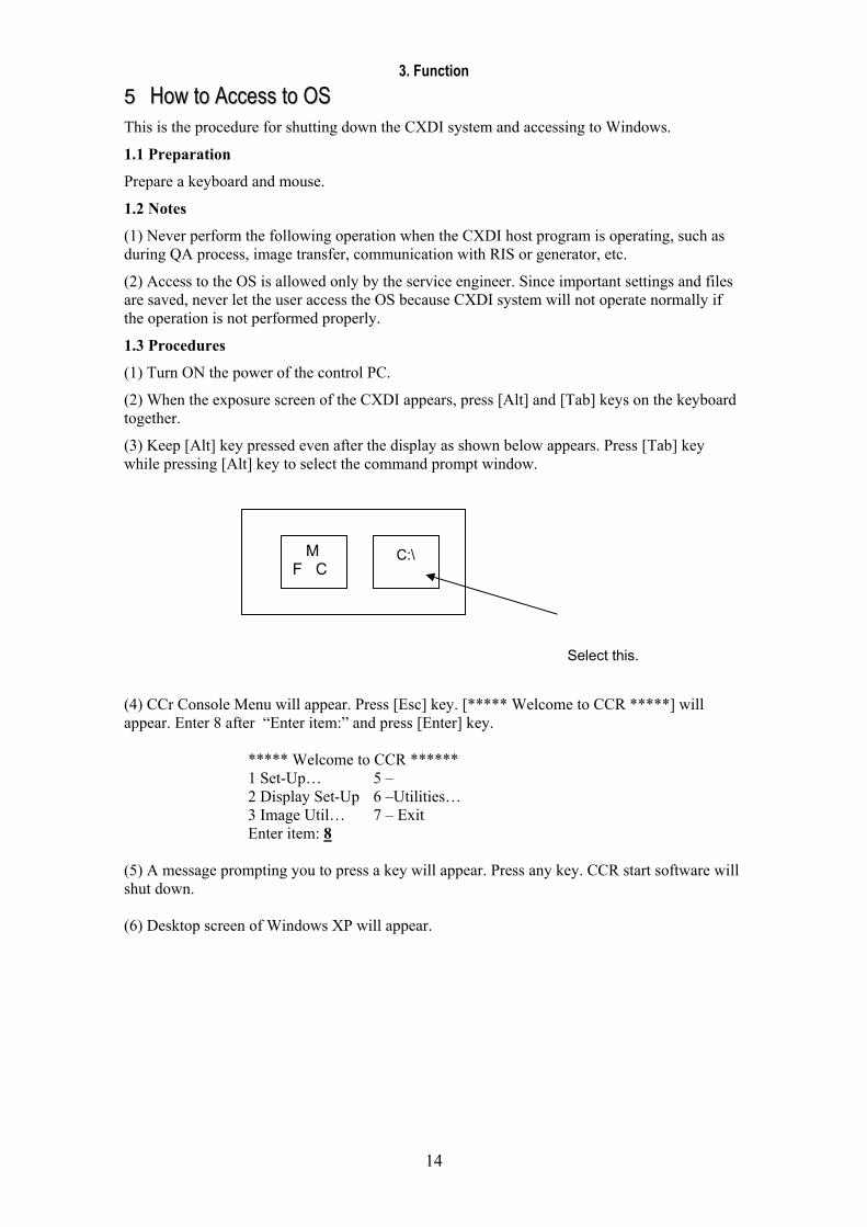
3. Function
14
55 HHooww ttoo AAcccceessss ttoo OOSS This is the procedure for shutting down the CXDI system and accessing to Windows.
1.1 Preparation
Prepare a keyboard and mouse.
1.2 Notes
(1) Never perform the following operation when the CXDI host program is operating, such as during QA process, image transfer, communication with RIS or generator, etc.
(2) Access to the OS is allowed only by the service engineer. Since important settings and files are saved, never let the user access the OS because CXDI system will not operate normally if the operation is not performed properly.
1.3 Procedures
(1) Turn ON the power of the control PC.
(2) When the exposure screen of the CXDI appears, press [Alt] and [Tab] keys on the keyboard together.
(3) Keep [Alt] key pressed even after the display as shown below appears. Press [Tab] key while pressing [Alt] key to select the command prompt window.
(4) CCr Console Menu will appear. Press [Esc] key. [***** Welcome to CCR *****] will appear. Enter 8 after “Enter item:” and press [Enter] key.
***** Welcome to CCR ****** 1 Set-Up… 5 – 2 Display Set-Up 6 –Utilities… 3 Image Util… 7 – Exit Enter item: 8
(5) A message prompting you to press a key will appear. Press any key. CCR start software will shut down. (6) Desktop screen of Windows XP will appear.
M F C
C:\
Select this.

CCXXDDII--5500GG // 5500CC
CCaannoonn IInncc.. JJaappaann CCooppyyrriigghhtt ((CC)) CCaannoonn IInncc.. MMeeddiiccaall TTeecchhnniiccaall SSeerrvviiccee DDeepptt.. AAllll rriigghhttss RReesseerrvveedd..
44.. RReeppaaiirr GGuuiiddee
PPrriinntteedd bbyy CCaannoonn IInncc..MMaarr.. 22000077 RReevv..0055

Content
1 Notes...................................................................................................................................... 1
1.1 For removing the base cover.......................................................................................... 1
1.2 About tabs exposed on the internal sensor unit.............................................................. 2
2 Disassemble/Reassemble....................................................................................................... 4
2.1 Removing Grip unit ....................................................................................................... 4
2.2 Removing the side cover................................................................................................ 5
2.3 Removing the cover ....................................................................................................... 6
2.4 Exchanging the sensor cable .......................................................................................... 7
2.5 Exchanging the PCB-50 LED...................................................................................... 17
2.6 Removing the PWB-50Di ............................................................................................ 21
2.7 Removing the PCB-50AD ........................................................................................... 22
2.8 Removing the PWB-40XRAY..................................................................................... 23
3 PCB Settings........................................................................................................................ 24
4 Operation Required for Replacing Parts.............................................................................. 26

4. Repair Guide
1
11 NNootteess 1.1 For removing the base cover The internal sensor unit is fixed with the top cover with base cover screws. Therefore, it gets free when the base cover is removed. Always keep the unit flat after removing the base cover. If the 50G Sensor Unit is set up or tilt, the internal sensor unit drops or shifts down.
Base Cover
Always keep the internal sensor unit flat after removing the base cover.
Top Cover
Internal Sensor Unit

4. Repair Guide
2
1.2 About tabs exposed on the internal sensor unit Never touch the tabs when disassembling or reassembling the unit. The tabs toward the grip are exposed on the internal sensor unit when the base cover is removed. Touching tabs may cause to damage them and hinder to scan an image appropriately. Besides they cannot be individually replaced or repaired.
Do not touch tabs when replacing the LED board.
Tabs (x 11)
Tab in Enlarged View
LED Board
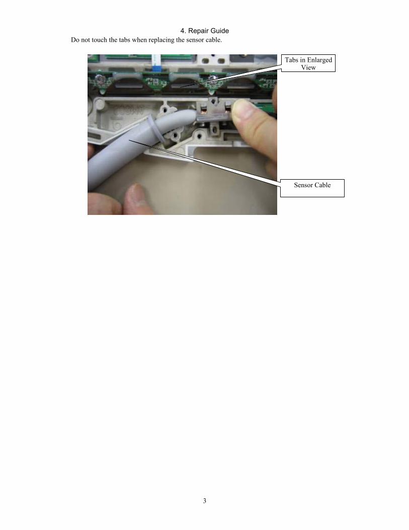
4. Repair Guide
3
Do not touch the tabs when replacing the sensor cable. Tabs in Enlarged
View
Sensor Cable
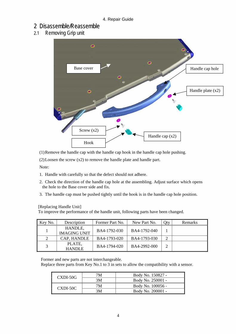
4. Repair Guide
4
22 DDiissaasssseemmbbllee//RReeaasssseemmbbllee 2.1 Removing Grip unit
Base cover Handle cap hole
Handle plate (x2)
Screw (x2) Handle cap (x2)
Hook
(1) Remove the handle cap with the handle cap hook in the handle cap hole pushing.
(2) Loosen the screw (x2) to remove the handle plate and handle part.
Note:
1. Handle with carefully so that the defect should not adhere.
2. Check the direction of the handle cap hole at the assembling. Adjust surface which opens the hole to the Base cover side and fix.
3. The handle cap must be pushed tightly until the hook is in the handle cap hole position.
[Replacing Handle Unit] To improve the performance of the handle unit, following parts have been changed.
Key No. Description Former Part No. New Part No. Qty Remarks
1 HANDLE, IMAGING UNIT BA4-1792-030 BA4-1792-040 1
2 CAP, HANDLE BA4-1793-020 BA4-1793-030 2
3 PLATE, HANDLE BA4-1794-020 BA4-2992-000 2
Former and new parts are not interchangeable. Replace three parts from Key No.1 to 3 in sets to allow the compatibility with a sensor.
7M Body No. 150827 - CXDI-50G 3M Body No. 250001 - 7M Body No. 100056 - CXDI-50C 3M Body No. 200001 -
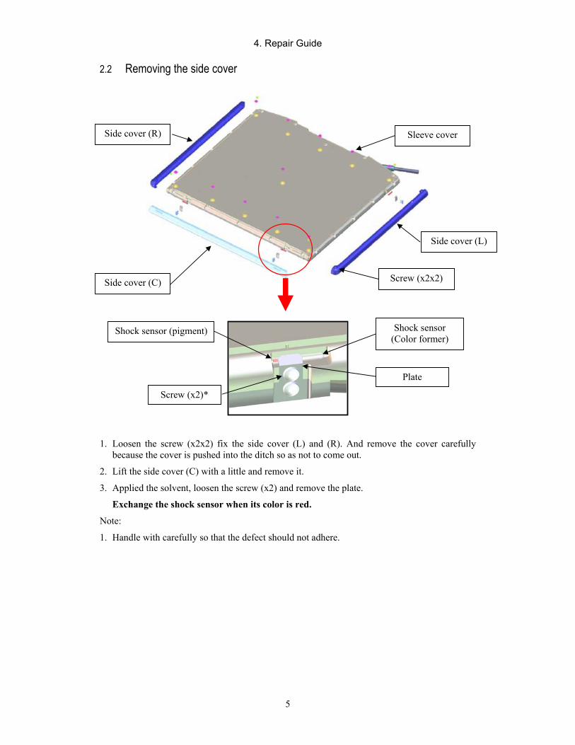
4. Repair Guide
5
2.2 Removing the side cover
1. Loosen the screw (x2x2) fix the side cover (L) and (R). And remove the cover carefully because the cover is pushed into the ditch so as not to come out.
2. Lift the side cover (C) with a little and remove it.
3. Applied the solvent, loosen the screw (x2) and remove the plate.
Exchange the shock sensor when its color is red.
Note:
1. Handle with carefully so that the defect should not adhere.
Side cover (R)
Side cover (L)
Sleeve cover
Side cover (C) Screw (x2x2)
Shock sensor (pigment) Shock sensor (Color former)
Screw (x2)*
Plate

4. Repair Guide
6
2.3 Removing the cover
Sleeve cover (x11)
Insulation sleeve (x11)
Screw M3x12 (x15)
Screw M3x8 (x15)
Screw M3x8 (x11)
Base cover
Insulation sleeve (x11)
Sleeve cover (x11)
1. Remove the sleeve cover (x11).
2. Remove the screw (M3x8) or screw (M3x12).
3. Remove the insulation sleeve and base cover.
Note:
1. Handle with carefully so that the defect should not adhere.
2. The insulation sleeve and sleeve cover must not be lost.
3. The order of detaching the screws fixes the base cover is not asked especially. At assembling, check the screw length, tight the screws evenly and be careful not to tighten it so much.
[Replacing Base Cover]
As the operation division was relocated, the base cover plate of CXDI-50G has been renewed. As a result, there are two types of nameplate. Only the manufacture is authorized to change the description of the plate according to the Pharmaceutical Law in Japan. You need to use the place with the same address as the previous plate when replacing. This is required only for Japanese market. Both of old and new plates are interchangeable for the other countries. *Application
7M Body No. 150079 - 7M Body No. 100009 - CXDI-50G 3M Body No. 250001 -
CXDI-50C 3M Body No. 200001 -

4. Repair Guide
7
2.4 Exchanging the sensor cable (1) Removing the Cable
1. Remove the screws (M3x8) x2 that fixes the cable clamp 1. 2. Remove the screws (M2.6x6) x2 that fixes the cable holder. 3. Remove the screws (M2.6x6) x2 that fixes the cable clamp 2. Do not lose the screw because it is held by the clamp cushion. 4. Disconnect the connectors from PCB-50LED and PWB-50Di. 5. Remove the sensor cable unit.
NOTES:
1. During assembly, lay out the signal cables carefully to they will not get caught by covers.
Sensor cable
Screw M2.6x6 (x2)
Cable clamp 2
Screw M3x8 (x2) Cable clamp 1
Disconnect the signal cable connector.
Screw M2.6x6 (x2)
Clamp cushion
The cable protect sheet is put under the cable so as to protect the sensor cable.
Bush
Disconnect the power cable connector.
Be careful not to get the cable caught between covers.
Bend the power line. Cable holder

4. Repair Guide
8
2. Place the bush into the case on the cover while adjusting the position of the bush so signal cables of 50G/50C sensor cable unit become straight.
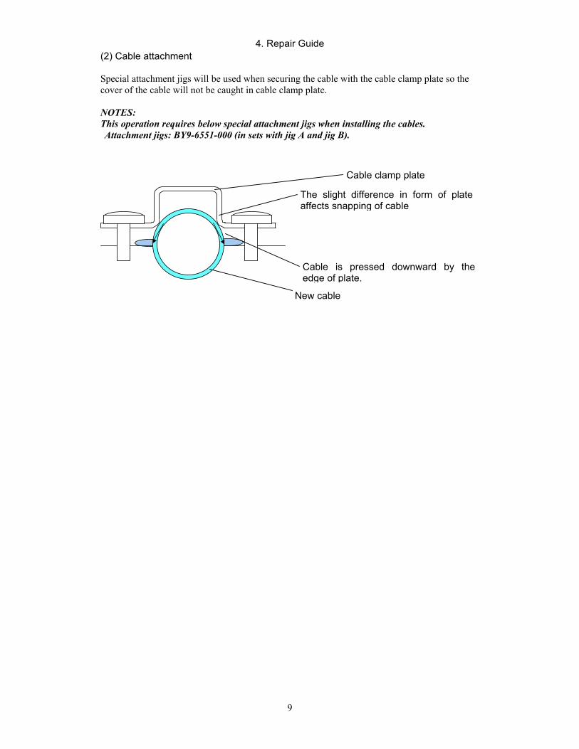
4. Repair Guide
9
(2) Cable attachment Special attachment jigs will be used when securing the cable with the cable clamp plate so the cover of the cable will not be caught in cable clamp plate. NOTES: This operation requires below special attachment jigs when installing the cables. Attachment jigs: BY9-6551-000 (in sets with jig A and jig B).
Cable clamp plate
The slight difference in form of plate affects snapping of cable
Cable is pressed downward by the edge of plate.
New cable
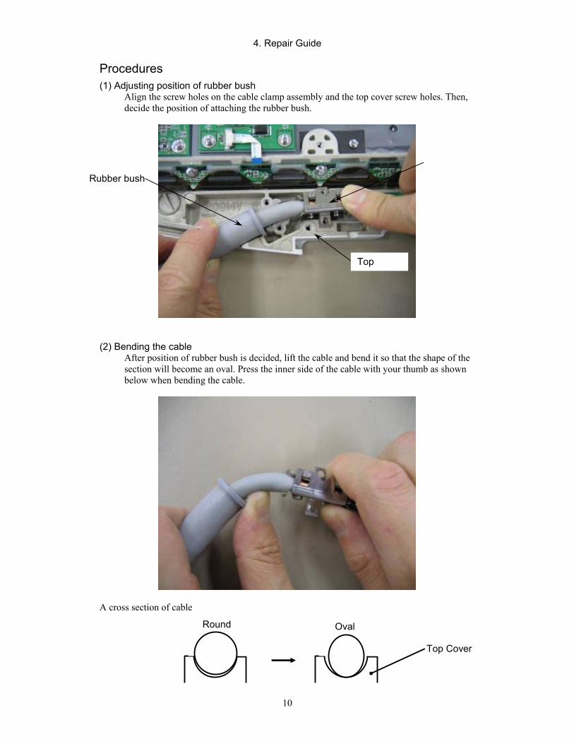
4. Repair Guide
10
Procedures (1) Adjusting position of rubber bush
Align the screw holes on the cable clamp assembly and the top cover screw holes. Then, decide the position of attaching the rubber bush.
(2) Bending the cable After position of rubber bush is decided, lift the cable and bend it so that the shape of the section will become an oval. Press the inner side of the cable with your thumb as shown below when bending the cable.
A cross section of cable
Top
Round Oval
Top Cover
Rubber bush
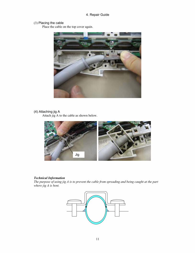
4. Repair Guide
11
(3) Placing the cable Place the cable on the top cover again.
(4) Attaching jig A Attach jig A to the cable as shown below.
Technical Information The purpose of using jig A is to prevent the cable from spreading and being caught at the part where jig A is bent.
Jig
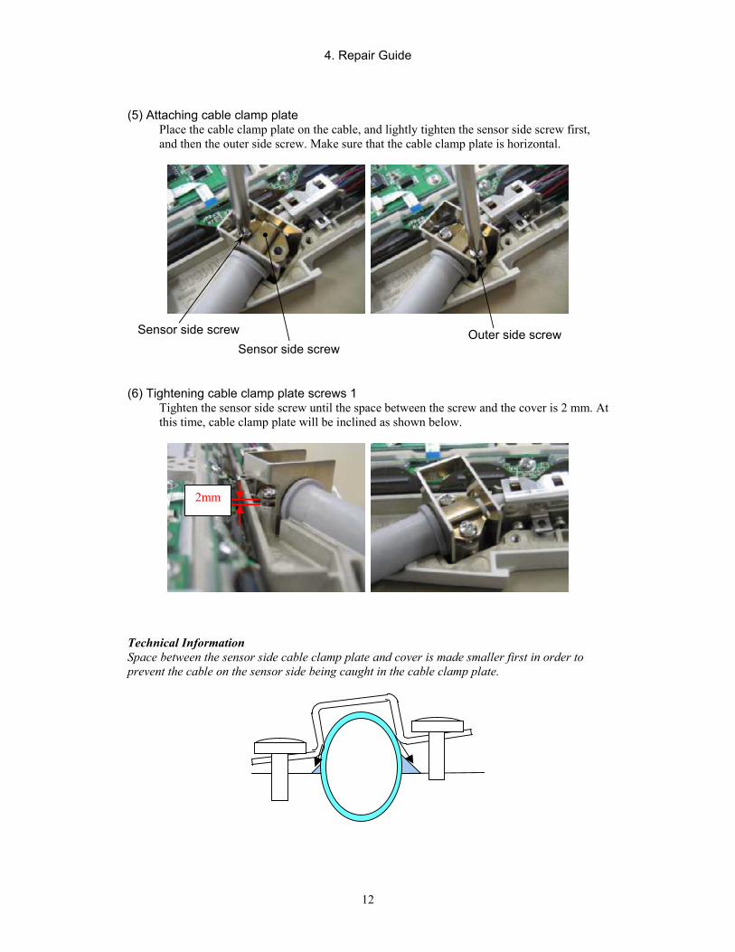
4. Repair Guide
12
(5) Attaching cable clamp plate Place the cable clamp plate on the cable, and lightly tighten the sensor side screw first, and then the outer side screw. Make sure that the cable clamp plate is horizontal.
(6) Tightening cable clamp plate screws 1 Tighten the sensor side screw until the space between the screw and the cover is 2 mm. At this time, cable clamp plate will be inclined as shown below.
‚Q‚ ‚
Technical Information Space between the sensor side cable clamp plate and cover is made smaller first in order to prevent the cable on the sensor side being caught in the cable clamp plate.
Sensor side screw Sensor side screw
Outer side screw
2mm
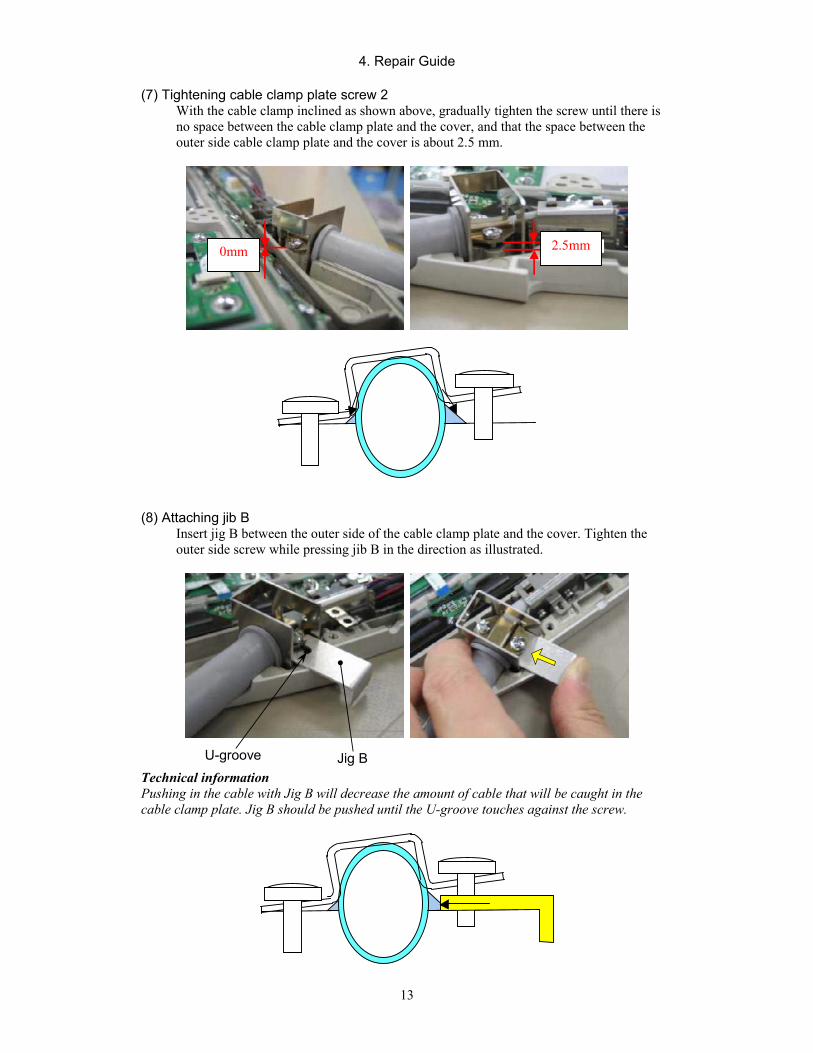
4. Repair Guide
13
(7) Tightening cable clamp plate screw 2
With the cable clamp inclined as shown above, gradually tighten the screw until there is no space between the cable clamp plate and the cover, and that the space between the outer side cable clamp plate and the cover is about 2.5 mm.
‚O‚ ‚
‚QD‚T‚ ‚
(8) Attaching jib B Insert jig B between the outer side of the cable clamp plate and the cover. Tighten the outer side screw while pressing jib B in the direction as illustrated.
Technical information Pushing in the cable with Jig B will decrease the amount of cable that will be caught in the cable clamp plate. Jig B should be pushed until the U-groove touches against the screw.
0mm 2.5mm
U-groove Jig B
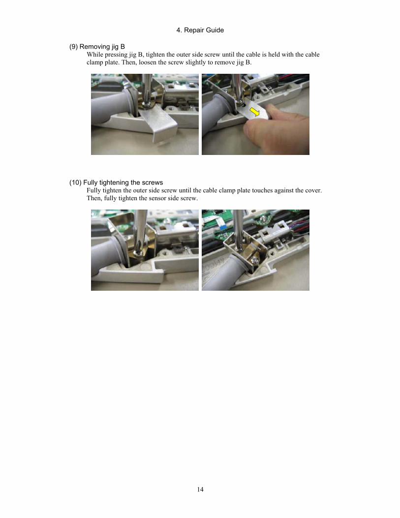
4. Repair Guide
14
(9) Removing jig B
While pressing jig B, tighten the outer side screw until the cable is held with the cable clamp plate. Then, loosen the screw slightly to remove jig B.
(10) Fully tightening the screws Fully tighten the outer side screw until the cable clamp plate touches against the cover. Then, fully tighten the sensor side screw.
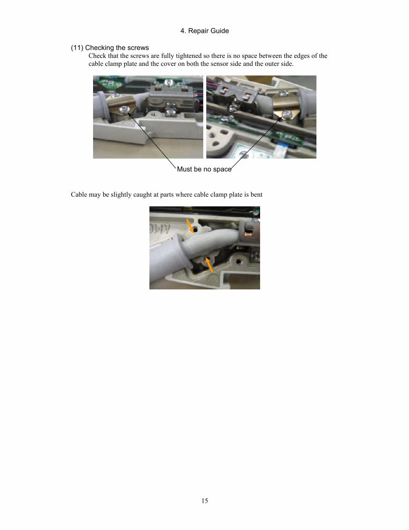
4. Repair Guide
15
(11) Checking the screws
Check that the screws are fully tightened so there is no space between the edges of the cable clamp plate and the cover on both the sensor side and the outer side.
Cable may be slightly caught at parts where cable clamp plate is bent
Must be no space
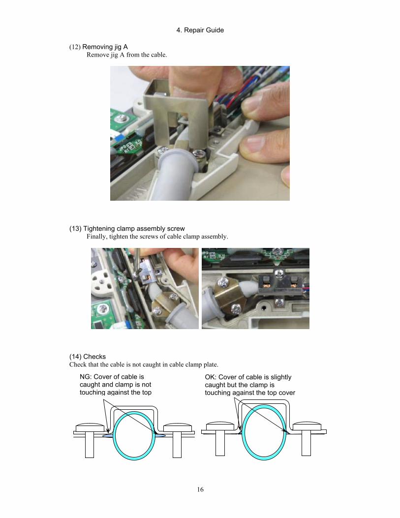
4. Repair Guide
16
(12) Removing jig A Remove jig A from the cable.
(13) Tightening clamp assembly screw Finally, tighten the screws of cable clamp assembly.
(14) Checks Check that the cable is not caught in cable clamp plate.
NG: Cover of cable is caught and clamp is not touching against the top
OK: Cover of cable is slightly caught but the clamp is touching against the top cover
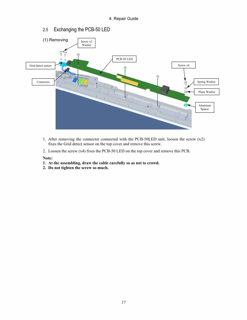
4. Repair Guide
17
2.5 Exchanging the PCB-50 LED
(1) Removing
1. After removing the connector connected with the PCB-50LED unit, loosen the screw (x2) fixes the Grid detect sensor on the top cover and remove this screw.
2. Loosen the screw (x4) fixes the PCB-50 LED on the top cover and remove this PCB.
Note: 1. At the assembling, draw the cable carefully so as not to crowd. 2. Do not tighten the screw so much.
Screw x2 Washer
Connector
Grid detect sensor
PCB-50 LED
Screw x4
Spring Washer
Plane Washer
Alminium Spacer
4. Repair Guide
18
(2) Attaching
Attachment of CXDI-50G/50C Grounding Strengthening Parts.
1. Requirements
(1) Grounding strengthening parts • PCB-50LED (BG7-2767-100) • Aluminum spacer (BA4-2434-000) • Plain washer M2.6mm (XD1-2100-267) • Spring washer M2.6mm (XD1-3100-267) If procedures in Service Manual Report CXDI-50G 05-013 has already been conducted, the above plain and spring washers should already be attached. (2). Tools • Torque screwdriver (recommended) • Tester (for measuring resistance value) • Cable attachment jig (BY9-6551) • Adhesive Cable attachment jig is used when attaching the new cable. For details, see Service Manual Report CXDI-50G 05-001. 2. Notes • Do not place anything in the chest pocket. Things in your pocket may fall out and damage the
sensor unit. • Be sure that the work place is well-ordered to prevent the chassis from getting scratched. • Be sure that the work place is protected against static electricity. 3. Disassembly See the service manual for the procedure for removing each parts. (1) Remove the rear cover from the sensor unit. (2) Remove the sensor cable. (3) Remove PCB-50LED. (Handle the FFC cable carefully.)
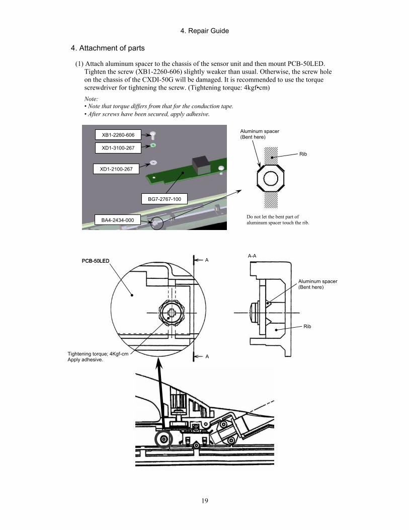
4. Repair Guide
19
4. Attachment of parts
(1) Attach aluminum spacer to the chassis of the sensor unit and then mount PCB-50LED. Tighten the screw (XB1-2260-606) slightly weaker than usual. Otherwise, the screw hole on the chassis of the CXDI-50G will be damaged. It is recommended to use the torque screwdriver for tightening the screw. (Tightening torque: 4kgf•cm) Note: • Note that torque differs from that for the conduction tape. • After screws have been secured, apply adhesive.
XD1-3100-267
XD1-2100-267
XB1-2260-606
BG7-2767-100
BA4-2434-000
Aluminum spacer(Bent here)
Rib
Do not let the bent part of aluminum spacer touch the rib.
PCB-50LED
Tightening torque; 4Kgf-cm Apply adhesive.
Aluminum spacer(Bent here)
PCB-50LED A
A
A-A
Rib
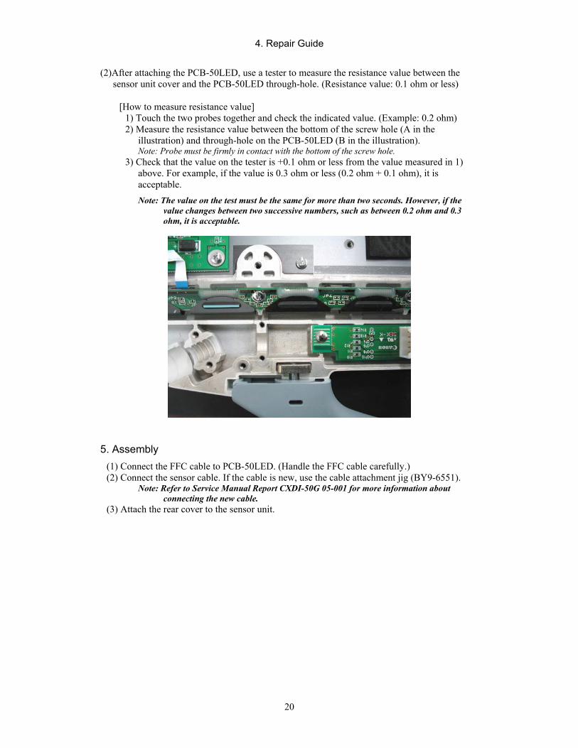
4. Repair Guide
20
(2)After attaching the PCB-50LED, use a tester to measure the resistance value between the sensor unit cover and the PCB-50LED through-hole. (Resistance value: 0.1 ohm or less)
[How to measure resistance value] 1) Touch the two probes together and check the indicated value. (Example: 0.2 ohm) 2) Measure the resistance value between the bottom of the screw hole (A in the
illustration) and through-hole on the PCB-50LED (B in the illustration). Note: Probe must be firmly in contact with the bottom of the screw hole.
3) Check that the value on the tester is +0.1 ohm or less from the value measured in 1) above. For example, if the value is 0.3 ohm or less (0.2 ohm + 0.1 ohm), it is acceptable. Note: The value on the test must be the same for more than two seconds. However, if the
value changes between two successive numbers, such as between 0.2 ohm and 0.3 ohm, it is acceptable.
5. Assembly (1) Connect the FFC cable to PCB-50LED. (Handle the FFC cable carefully.) (2) Connect the sensor cable. If the cable is new, use the cable attachment jig (BY9-6551).
Note: Refer to Service Manual Report CXDI-50G 05-001 for more information about connecting the new cable.
(3) Attach the rear cover to the sensor unit.
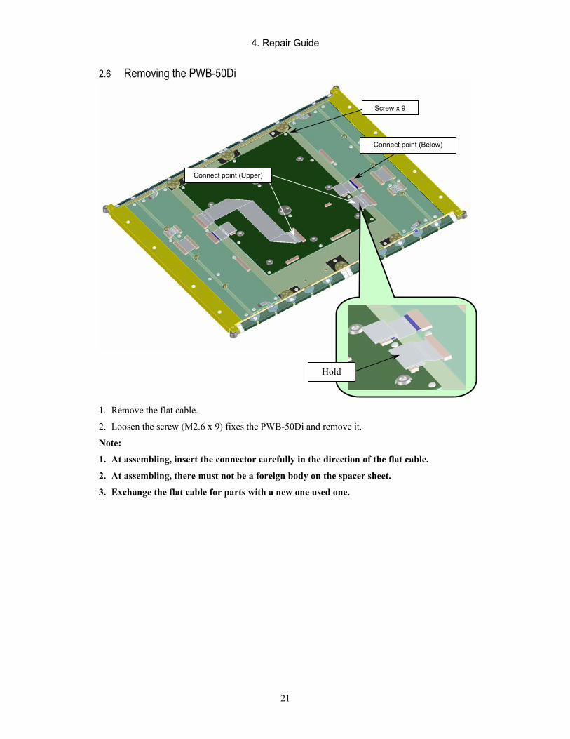
4. Repair Guide
21
2.6 Removing the PWB-50Di
1. Remove the flat cable.
2. Loosen the screw (M2.6 x 9) fixes the PWB-50Di and remove it.
Note:
1. At assembling, insert the connector carefully in the direction of the flat cable.
2. At assembling, there must not be a foreign body on the spacer sheet.
3. Exchange the flat cable for parts with a new one used one.
Screw x 9
Hold
Connect point (Upper)
Connect point (Below)

4. Repair Guide
22
2.7 Removing the PCB-50AD
1. Remove the flat cable.
2. Loosen the screw (M2.6 x 16) fixes the PCB-50AD and remove it.
Note:
1. At assembling, insert the connector carefully in the direction of the flat cable.
2. Exchange the flat cable for parts with a new one used one.
Contact position
Screw x 16
At attaching the flat cable, perform the work with very carefully.
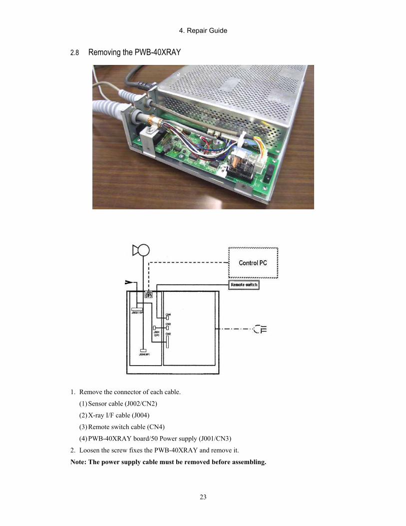
4. Repair Guide
23
2.8 Removing the PWB-40XRAY
1. Remove the connector of each cable.
(1) Sensor cable (J002/CN2)
(2) X-ray I/F cable (J004)
(3) Remote switch cable (CN4)
(4) PWB-40XRAY board/50 Power supply (J001/CN3)
2. Loosen the screw fixes the PWB-40XRAY and remove it.
Note: The power supply cable must be removed before assembling.
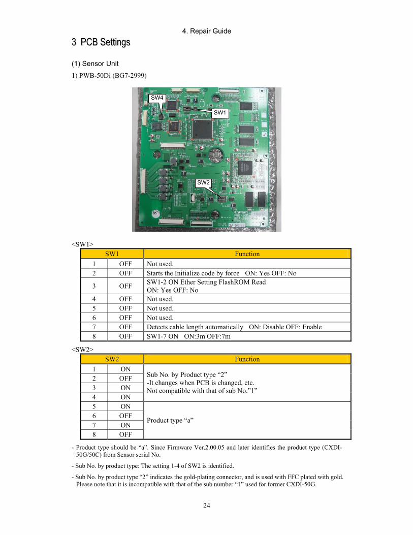
4. Repair Guide
24
33 PPCCBB SSeettttiinnggss (1) Sensor Unit
1) PWB-50Di (BG7-2999)
<SW1> SW1 Function
1 OFF Not used. 2 OFF Starts the Initialize code by force ON: Yes OFF: No
3 OFF SW1-2 ON Ether Setting FlashROM Read ON: Yes OFF: No
4 OFF Not used. 5 OFF Not used. 6 OFF Not used. 7 OFF Detects cable length automatically ON: Disable OFF: Enable 8 OFF SW1-7 ON ON:3m OFF:7m
<SW2> SW2 Function
1 ON 2 OFF 3 ON 4 ON
Sub No. by Product type “2” -It changes when PCB is changed, etc. Not compatible with that of sub No.”1”
5 ON 6 OFF 7 ON 8 OFF
Product type “a”
- Product type should be “a”. Since Firmware Ver.2.00.05 and later identifies the product type (CXDI-50G/50C) from Sensor serial No.
- Sub No. by product type: The setting 1-4 of SW2 is identified.
- Sub No. by product type “2” indicates the gold-plating connector, and is used with FFC plated with gold. Please note that it is incompatible with that of the sub number “1” used for former CXDI-50G.
SW4
SW1
SW2
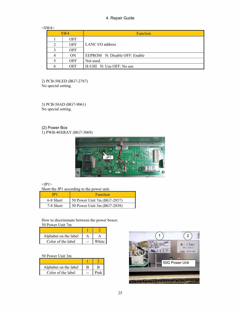
4. Repair Guide
25
<SW4>
SW4 Function 1 OFF 2 OFF 3 OFF
LANC I/O address
4 ON EEPROM N: Disable OFF: Enable 5 OFF Not used. 6 OFF H-UHI N: Use OFF: No use
2) PCB-50LED (BG7-2767) No special setting.
3) PCB-50AD (BG7-9061) No special setting.
(2) Power Box 1) PWB-40XRAY (BG7-3069)
<JP1> Short the JP1 according to the power unit.
JP1 Function 6-8 Short 50 Power Unit 7m (BG7-2857) 7-8 Short 50 Power Unit 3m (BG7-2858)
How to discriminate between the power boxes: 50 Power Unit 7m
1 2 Alphabet on the label A A
Color of the label -- White
50 Power Unit 3m 1 2
Alphabet on the label B B Color of the label -- Pink
JP1
1 2
50G Power Unit
4. Repair Guide
26
44 OOppeerraattiioonn RReeqquuiirreedd ffoorr RReeppllaacciinngg PPaarrttss Perform the following operations when the unit is replaced.
4.1 Sensor unit
(1) When sensor unit is replaced 1) Set the IP address. (This operation is not required if the default IP address is used.)
Refer to “Imaging unit IP address setting” in the Tool Software Operation Manual for Ethernet.
2) Check the version of firmware and PLD code version.
Refer to “(2) Checking the Firmware Version” in “5.2.5 Settings” in “2.5 Installation” of “2. Installation Manual”.
3) Install the firmware and PLD code as required.
Refer to “(3) Installing Firmware and PLD Code” in “5.2.5 Settings” in “2.5 Installation” of “2. Installation Manual”.
4) Identify the sensor unit.
Refer to “(6) Identifying the Sensor Units” in “5.2.5 Settings” in “2.5 Installation” of “2. Installation Manual”.
5) Change total number of exposures. (Basically the counter should be reset to “0” when the sensor unit is replaced.)
Refer to “(13) Changing the Total Image Count” in “5.2.5 Settings” in “2.5 Installation” of “2. Installation Manual”.
6) Check the image quality.
Refer to “5.2.6 Image Quality” in “2.5 Installation” of “2. Installation Manual”.
7) Back up the data. (Back up the data to FD as required.)
Refer to “Backing Up when Installing” and “(15) Backing Up Setting Data to FD” in “5.2.5 Settings” in “2.5 Installation” of “2. Installation Manual”.
(2) When PWB-50Di (BG7-2999) is replaced 1) Set the PCB dipswitches.
Refer to “2. Settings” of “4. Repair Guide”.
2) Set the IP address. (This operation is not required if the default IP address is used.)
Refer to “Imaging unit IP address setting” in the Tool Software Operation Manual for Ethernet.
2) Check the version of firmware and PLD code version.
Refer to “(2) Checking the Firmware Version” in “5.2.5 Settings” in “2.5 Installation” of “2. Installation Manual”.
3) Install the firmware and PLD code as required.
Refer to “(3) Installing Firmware and PLD Code” in “5.2.5 Settings” in “2.5 Installation” of “2. Installation Manual”.

4. Repair Guide
27
4) Install the sensor serial number.
Refer to “(4) Checking the Sensor Serial Number” in “5.2.5 Settings” in “2.5 Installation” of “2. Installation Manual”.
5) Install the sensor data file.
Refer to “DP File Write Tool Software” in the Tool Software Operation Manual for Ethernet.
To perform this operation, “Sensor Data File FD” that comes with the sensor unit is required.
6) Check the image quality.
Refer to “5.2.6 Image Quality” in “5.2.5 Settings” in “2.5 Installation” of “2. Installation Manual”.
(3) When PCB-50LED (BG7-2767) is replaced 1) Check that the LED lights.
2) Check the image quality.
Refer to “5.2.6 Image Quality” in “5.2.5 Settings” in “2.5 Installation” of “2. Installation Manual”.
(4) When PCB-50AD (BG7-2770) is replaced 1) Check the image quality.
Refer to “5.2.6 Image Quality” in “5.2.5 Settings” in “2.5 Installation” of “2. Installation Manual”.
4.2 Power box
(1) When PWB-40XRAY (BG7-3069) is replaced 1) Set the jumper pins on the PCB.
Refer to “(2) Power Box” in “2 PCB settings” in “4. Repair Guide”.
2) Check that the system starts up normally and that operations such as exposure, images capture and data transfer are performed normally.
(2) When 50 Power Unit 7m (BG7-2857) / 3m (BG7-2858) is replaced
1) Check that the system starts up normally and that operations such as exposure, images capture and data transfer are performed normally.


55.. PPaarrttss CCaattaalloogg
PPrriinntteedd bbyy CCaannoonn IInncc.. MMaarrcchh 22000077 RReevv..0044
CCaannoonn IInncc.. JJaappaann CCooppyyrriigghhtt ((CC)) CCaannoonn IInncc.. MMeeddiiccaall TTeecchhnniiccaall SSeerrvviiccee DDeepptt.. AAllll rriigghhttss RReesseerrvveedd..
CCXXDDII--5500GG//5500CC

CXDI-SYSTEM Rev.04
CONTENTS
CXDI-50G/50C·········································································································· 1
IMAGING UNIT ······································································································· 2
POWER BOX ············································································································ 3
REMOTE SWITCH UNIT ························································································ 4
IMAGING UNIT (Electrical) ···················································································· 5
POWER BOX (Electrical) ························································································· 6
INDEX OF PARTS NUMBERS ··············································································· 7

CXDI-SYSTEM 1-1 Rev.04
CXDI-50G/50C
Key NO. Description Part No. Q’ty 1................. IMAGING UNIT ...................................................................................... 1 2................. 50G POWER BOX (7m).................................... Y67-2669-040 .............. 1
50G POWER BOX (3m) ........................................ Y67-2670-040 .............. 1 50C POWER BOX (7m) ........................................ Y67-2786-000 .............. 1 50C POWER BOX (3m) ........................................ Y67-2787-000 .............. 1
3................. CABLE UNIT, X-RAY I/F................................ BH6-5728-040 ............. 1 4................. SWITCH UNIT, REMOTE ............................... BG7-2772-060 ............. 1 5................. CABLE UNIT, POWER, 100V ......................... BH4-6494-020 ............. 1 6................. CABLE UNIT, POWER, 120V ......................... BH4-2385-100 ............. 1 7................. CABLE UNIT, POWER, 230V ......................... BH4-6217-030 ............. 1 8................. CLAMP, CABLE............................................... WT2-5859-020............. 1 9................. SCREW.............................................................. XB1-1400-603 ............. 1
Key No.1 Key No.2
Key No.3 Key No.4
© Canon Inc.
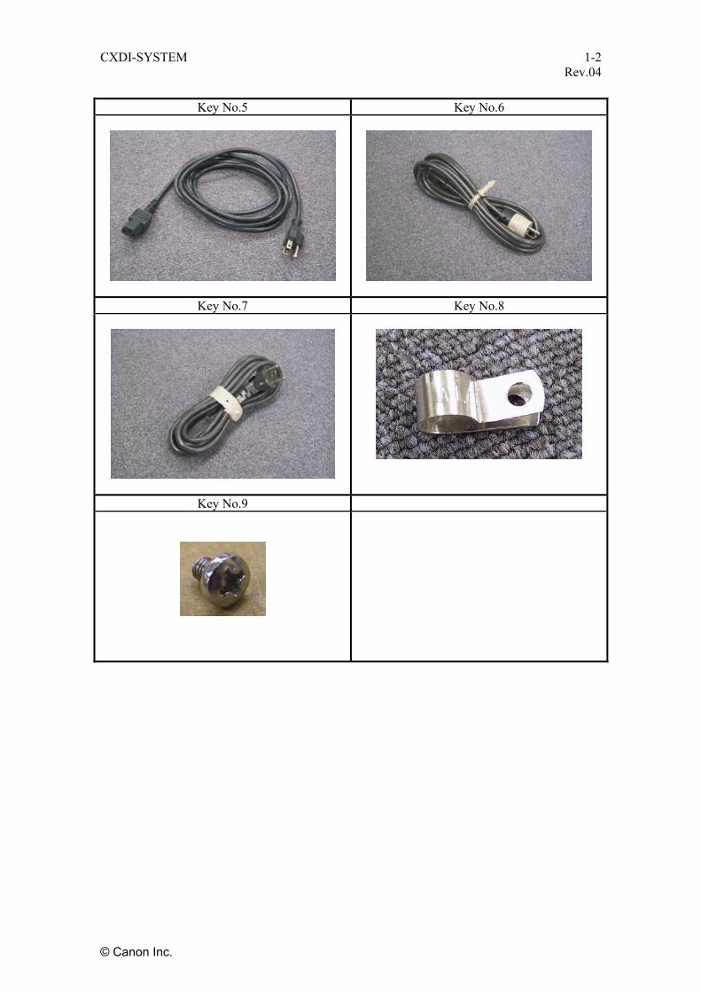
CXDI-SYSTEM 1-2 Rev.04
Key No.5 Key No.6
Key No.7 Key No.8
Key No.9
© Canon Inc.

CXDI-SYSTEM 2-1 Rev.04
IMAGING UNIT (CXDI-50G/50C)
KEY NO. PARTS NO. Q’TY DESCRIPTION MEMO
Y67-2671-000 1 COVER UNIT, BASE For 50G with Utsunomiya address
Y67-2671-030 1 COVER UNIT, BASE For 50G with Shimomaruko address 1
Y67-2801-000 1 COVER UNIT, BASE For 50C with Shimomaruko address
2 Y67-2783-000 1 COVER, SIDE (L) W/O SHEET, Q
3 Y67-2784-000 1 COVER, SIDE (R) W/O SHEET, Q
4 BA4-1786-050 1 COVER, SIDE (C) W/O SHEET, Q
5 BA4-2144-000 2 SHEET, Q
6 BA4-2144-000 2 SHEET, Q
7 BA4-2144-000 2 SHEET, Q
8 BA4-1783-000 4 SCREW
9 XB1-2301-206 5 SCREW
Y67-2692-030 1 CABLE UNIT, 7M 10
Y67-2693-030 1 CABLE UNIT, 3M Application of the base cover unit with Shimomaru address
7M Body No. 150079- 7M Body No. 100009- CXDI-50G 3M Body No. 250001- CXDI-50C 3M Body No. 200001-
10 8 9
1
3 2
4
4
3
2
7
6
5
© Canon Inc.
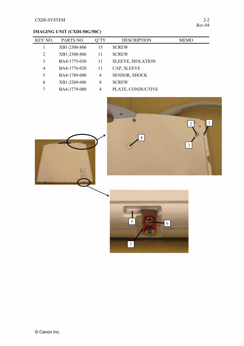
CXDI-SYSTEM 2-2 Rev.04
IMAGING UNIT (CXDI-50G/50C)
KEY NO. PARTS NO. Q’TY DESCRIPTION MEMO 1 XB1-2300-806 15 SCREW 2 XB1-2300-806 11 SCREW 3 BA4-1775-030 11 SLEEVE, ISOLATION 4 BA4-1776-020 11 CAP, SLEEVE 5 BA4-1789-000 4 SENSOR, SHOCK 6 XB1-2260-606 8 SCREW 7 BA4-1779-000 4 PLATE, CONDUCTIVE
1
3
2
4
7
5 6
© Canon Inc.

CXDI-SYSTEM 2-3 Rev.04
IMAGING UNIT (CXDI-50G)
KEY NO. PARTS NO. Q’TY DESCRIPTION MEMO 1 BG7-2999-040 1 PCB UNIT, DIGITAL Gold plated 2 BG7-2767-100 1 PCB UNIT, LED Gold plated 3 BG7-9061-160 2 PCB UNIT, A/D Gold plated 4 BA4-1766-040 1 SPACER, SHEET 5 BF0-5372-020 1 CLAMP UNIT 6 BH6-5700-000 1 CABLE, FLAT 7 BH6-7580-000 1 CABLE, FLAT Gold plated 8 BH6-7581-000 1 CABLE, FLAT Gold plated 9 BH6-5720-000 1 CABLE, FLAT
10 BH6-5722-000 1 CABLE, FLAT 11 BH6-7582-000 1 CABLE, FLAT Gold plated 12 BH6-7583-020 1 CABLE, FLAT Gold plated 13 BH6-7584-000 1 CABLE, FLAT Gold plated 14 XB1-2260-606 8 SCREW 15 XB1-2260-606 9 SCREW 16 XB1-2260-606 4 SCREW 17 BH6-5730-000 1 SWITCH UNIT, GRID 18 XA1-1200-506 2 SCREW 19 BA4-2180-000 1 CLAMP, CABLE 20 XB1-2300-806 2 SCREW 21 XB1-2260-606 2 SCREW 22 XB1-2260-606 4 SCREW 23 XB1-2260-606 1 SCREW 24 XD1-3100-267 1 WASHER, SPRING 25 XD1-2100-267 1 WASHER, PLAIN 26 BA4-2434-000 1 SPACER, AL 27 BA4-1778-000 2 NUT, PLATE SUS
© Canon Inc.
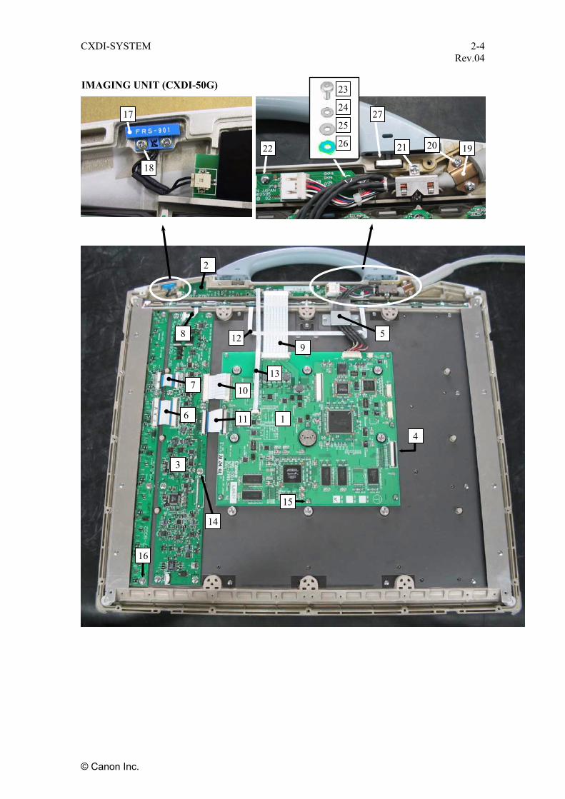
CXDI-SYSTEM 2-4 Rev.04
IMAGING UNIT (CXDI-50G)
27
26
25
24
23
22 21 20 19
17
18
2
8 5 129
137 10
6 11 1
4
3
14
15
16
© Canon Inc.

CXDI-SYSTEM 2-5 Rev.04
IMAGING UNIT (CXDI-50C)
KEY NO. PARTS NO. Q’TY DESCRIPTION MEMO 1 BG7-2999-040 1 PCB UNIT, DIGITAL Gold plated 2 BG7-2767-100 1 PCB UNIT, LED Gold plated 3 BG7-9061-160 2 PCB UNIT, A/D Gold plated 4 BA4-1766-040 1 SPACER, SHEET 5 BF0-5372-020 1 CLAMP UNIT 6 BH6-5700-000 2 CABLE, FLAT 7 BH6-7580-000 2 CABLE, FLAT Gold plated 8 BH6-7581-000 4 CABLE, FLAT Gold plated 9 BH6-5720-000 1 CABLE, FLAT
10 BH6-5721-000 1 CABLE, FLAT 11 BH6-5722-000 1 CABLE, FLAT 12 BH6-7582-000 2 CABLE, FLAT Gold plated 13 BH6-7584-000 1 CABLE, FLAT Gold plated 14 XB1-2260-606 16 SCREW 15 XB1-2260-606 9 SCREW 16 XB1-2260-606 8 SCREW 17 BH6-5730-000 1 SWITCH UNIT, GRID 18 XA1-1200-506 2 SCREW 19 BA4-2180-000 1 CLAMP, CABLE 20 XB1-2300-806 2 SCREW 21 XB1-2260-606 2 SCREW 22 XB1-2260-606 4 SCREW 23 XB1-2260-606 1 SCREW 24 XD1-3100-267 1 WASHER, SPRING 25 XD1-2100-267 1 WASHER, PLAIN 26 BA4-2434-000 1 SPACER, AL 27 BA4-1778-000 2 NUT, PLATE
© Canon Inc.

CXDI-SYSTEM 2-6 Rev.04
IMAGING UNIT (CXDI-50C)
27
26
25
24
23
22 21 20
19
17
18
5
2
8 9
13
7 11 10
12 1 6 12
3
14
15
4
16
© Canon Inc.
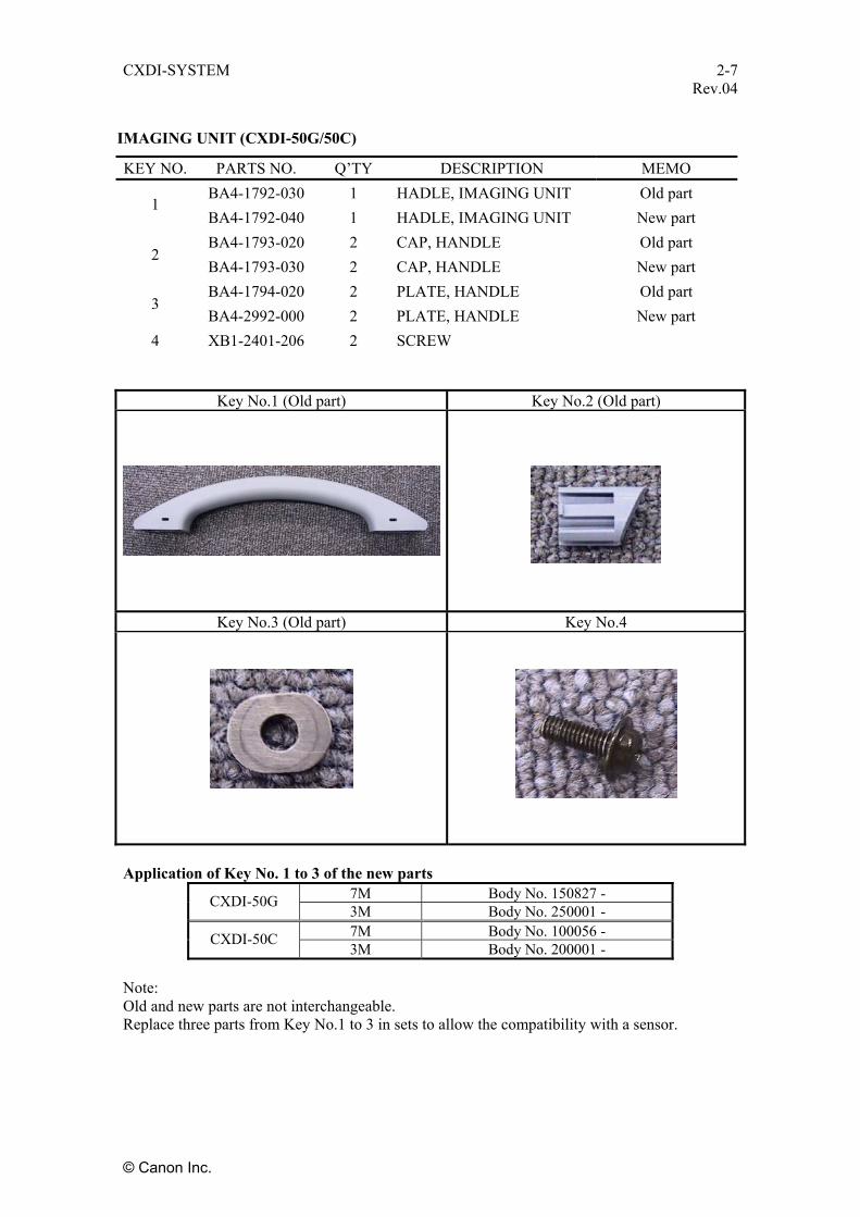
CXDI-SYSTEM 2-7 Rev.04
IMAGING UNIT (CXDI-50G/50C)
KEY NO. PARTS NO. Q’TY DESCRIPTION MEMO BA4-1792-030 1 HADLE, IMAGING UNIT Old part
1 BA4-1792-040 1 HADLE, IMAGING UNIT New part BA4-1793-020 2 CAP, HANDLE Old part
2 BA4-1793-030 2 CAP, HANDLE New part BA4-1794-020 2 PLATE, HANDLE Old part
3 BA4-2992-000 2 PLATE, HANDLE New part
4 XB1-2401-206 2 SCREW
Key No.1 (Old part) Key No.2 (Old part)
Key No.3 (Old part) Key No.4
Application of Key No. 1 to 3 of the new parts
7M Body No. 150827 - CXDI-50G 3M Body No. 250001 - 7M Body No. 100056 - CXDI-50C 3M Body No. 200001 -
Note: Old and new parts are not interchangeable. Replace three parts from Key No.1 to 3 in sets to allow the compatibility with a sensor.
© Canon Inc.

CXDI-SYSTEM 3-1 Rev.04
POWER BOX (CXDI-50G/50C)
KEY NO. PARTS NO. Q’TY DESCRIPTION MEMO 1 XB1-2300-406 3 SCREW 2 XB1-2300-806 4 SCREW 3 BA4-1803-000 4 PAD 4 XB1-2300-406 8 SCREW 5 BA4-1800-020 1 UPPER COVER, POWER BOX 6 XB2-7300-606 5 SCREW, W/WASHER 7 XB1-2300-406 2 SCREW 8 XB1-2300-406 2 SCREW 9 BA4-1802-000 1 COVER, CABLE
10 XB1-1400-603 1 SCREW 11 XD1-4200-402 1 WASHER, TOOTHED LOCK
1
3
2
4
7 1110 9
5 8
6
© Canon Inc.
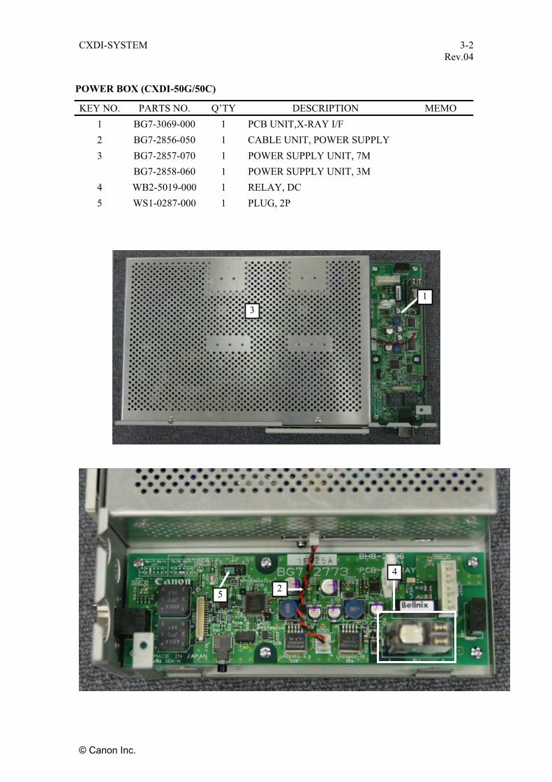
CXDI-SYSTEM 3-2 Rev.04
POWER BOX (CXDI-50G/50C)
KEY NO. PARTS NO. Q’TY DESCRIPTION MEMO 1 BG7-3069-000 1 PCB UNIT,X-RAY I/F 2 BG7-2856-050 1 CABLE UNIT, POWER SUPPLY 3 BG7-2857-070 1 POWER SUPPLY UNIT, 7M BG7-2858-060 1 POWER SUPPLY UNIT, 3M
4 WB2-5019-000 1 RELAY, DC 5 WS1-0287-000 1 PLUG, 2P
4
1 3
2 5
© Canon Inc.
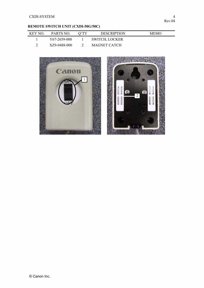
CXDI-SYSTEM 4 Rev.04
REMOTE SWITCH UNIT (CXDI-50G/50C)
KEY NO. PARTS NO. Q’TY DESCRIPTION MEMO 1 Y67-2659-000 1 SWITCH, LOCKER 2 XZ9-0488-000 2 MAGNET CATCH
1
2
© Canon Inc.

CXDI-SYSTEM 5-1 Rev.04
CXDI-50G (Electrical)
SYMBOL PART NO. DESCRIPTION REMARKS CA1 Y67-2692-030 CABLE UNIT, 7M Y67-2693-030 CABLE UNIT, 3M CA2 BH6-7582-000 CABLE, FLAT Gold plated CA3 BH6-5722-000 CABLE, FLAT CA4 BH6-5700-000 CABLE, FLAT CA5 BH6-7580-000 CABLE, FLAT Gold plated CA6 BH6-7581-000 CABLE, FLAT Gold plated CA7 BH6-7584-000 CABLE, FLAT Gold plated CA8 BH6-5720-000 CABLE, FLAT CA9 BH6-7583-020 CABLE, FLAT Gold plated SW1 BH6-5730-000 SWITCH UNIT, GRID W/CABLE PB1 BG7-2999-040 PCB UNIT, DIGITAL Gold plated PB2 BG7-9061-160 PCB UNIT, A/D Gold plated PB3 BG7-2767-100 PCB UNIT, LED Gold plated
© Canon Inc.
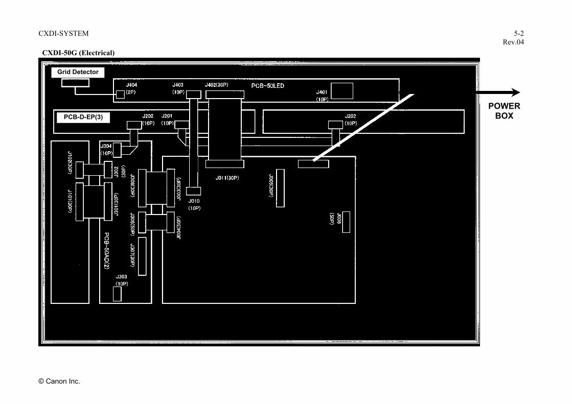
YSTEM 5-2 Rev.04
POWER BOX
CA1
PCB-D-EP (2)
CA9
PB3
PWB-50Di
PB1
CA8
CA7
CA3
CA2
CA6
PB2
CA4
CA5
CXDI-S
© Canon Inc.
CXDI-50G (Electrical)
PCB-D-EP(3)
SW1 Grid Detector
PCB
-50A(2)
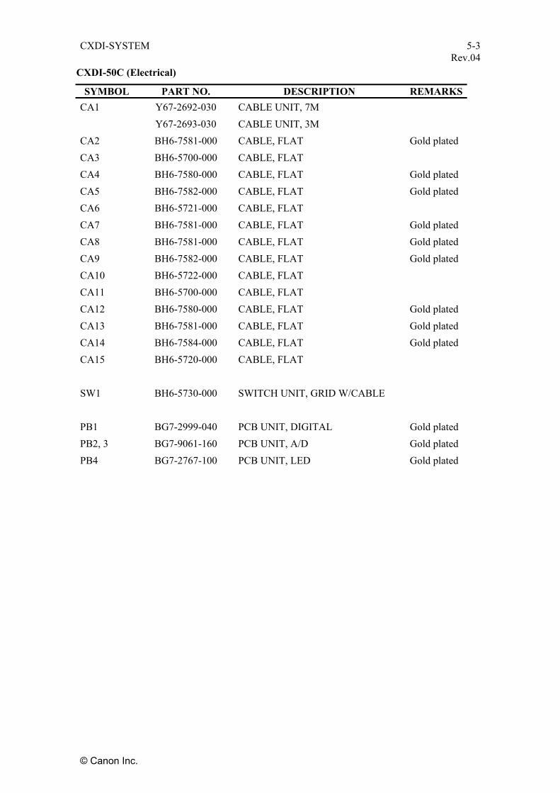
CXDI-SYSTEM 5-3 Rev.04
CXDI-50C (Electrical)
SYMBOL PART NO. DESCRIPTION REMARKS CA1 Y67-2692-030 CABLE UNIT, 7M Y67-2693-030 CABLE UNIT, 3M CA2 BH6-7581-000 CABLE, FLAT Gold plated CA3 BH6-5700-000 CABLE, FLAT CA4 BH6-7580-000 CABLE, FLAT Gold plated CA5 BH6-7582-000 CABLE, FLAT Gold plated CA6 BH6-5721-000 CABLE, FLAT CA7 BH6-7581-000 CABLE, FLAT Gold plated CA8 BH6-7581-000 CABLE, FLAT Gold plated CA9 BH6-7582-000 CABLE, FLAT Gold plated CA10 BH6-5722-000 CABLE, FLAT CA11 BH6-5700-000 CABLE, FLAT CA12 BH6-7580-000 CABLE, FLAT Gold plated CA13 BH6-7581-000 CABLE, FLAT Gold plated CA14 BH6-7584-000 CABLE, FLAT Gold plated CA15 BH6-5720-000 CABLE, FLAT SW1 BH6-5730-000 SWITCH UNIT, GRID W/CABLE PB1 BG7-2999-040 PCB UNIT, DIGITAL Gold plated PB2, 3 BG7-9061-160 PCB UNIT, A/D Gold plated PB4 BG7-2767-100 PCB UNIT, LED Gold plated
© Canon Inc.

CXDI-SYSTEM 5-4 Rev.04
© Canon Inc.
POWER BOX
CA3
CA4
CA2
CA7
PB2
CA5 CA6
PCB-D-EP(2)
PCB-D-EP(1)
PB4
PB1
CA15 CA14
CA10
CA9
CA8
CA13
PB3
CXDI-50C (Electrical)
PCB-D-EP(3)
CA12
CA11
PCB-D-EP(4)
Grid Detector
SW1
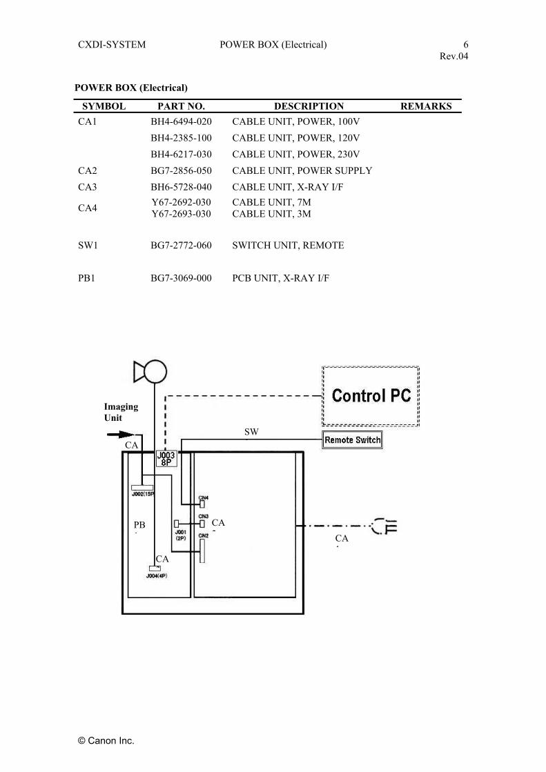
CXDI-SYSTEM POWER BOX (Electrical) 6 Rev.04
© Canon Inc.
SYMBOL PART NO. DESCRIPTION REMARKS CA1 BH4-6494-020 CABLE UNIT, POWER, 100V BH4-2385-100 CABLE UNIT, POWER, 120V BH4-6217-030 CABLE UNIT, POWER, 230V CA2 BG7-2856-050 CABLE UNIT, POWER SUPPLY CA3 BH6-5728-040 CABLE UNIT, X-RAY I/F
CA4 Y67-2692-030 Y67-2693-030
CABLE UNIT, 7M CABLE UNIT, 3M
SW1 BG7-2772-060 SWITCH UNIT, REMOTE PB1 BG7-3069-000 PCB UNIT, X-RAY I/F
POWER BOX (Electrical)
Imaging Unit
CA4
PB1
CA3
CA2
SW1
CA1

CXDI-SYSTEM 7-1 Rev.04
INDEX OF PARTS NUMBERS (CXDI-50G/50C)
PARTS NO. PAGE REVISION NO. - REPORT NO. BA4-1766-040 2-3,2-5 - - - - - BA4-1775-030 2-2 - - - - - BA4-1776-020 2-2 - - - - - BA4-1783-000 1-2 - - - - - BA4-1786-050 1-2 - - - - - BA4-1788-000 2-3,2-5 - - - - - BA4-1789-000 2-2 - - - - - BA4-1792-030 2-7 - - - - - BA4-1793-020 2-7 - - - - - BA4-1794-020 2-7 - - - - - BA4-1800-020 3-1 - - - - - BA4-1802-000 3-1 - - - - - BA4-1803-000 3-1 - - - - - BA4-2144-000 1-2 - - - - - BA4-2180-000 2-3,2-5 BA4-2434-000 2-3,2-5 - - - - - BF0-5372-020 2-3,2-5 - - - - - BG7-2767-100 2-3,2-5,5-1,5-3 - - - - - BG7-2772-060 1-1,6 - - - - - BG7-2856-050 3-2,6 - - - - - BG7-2857-070 3-2 - - - - - BG7-2858-060 3-2 - - - - - BG7-2999-040 2-3,2-5,5-1,5-3 - - - - - BG7-3069-000 3-2,6 - - - - - BG7-9061-160 2-3,2-5,5-1,5-3 - - - - -
© Canon Inc.
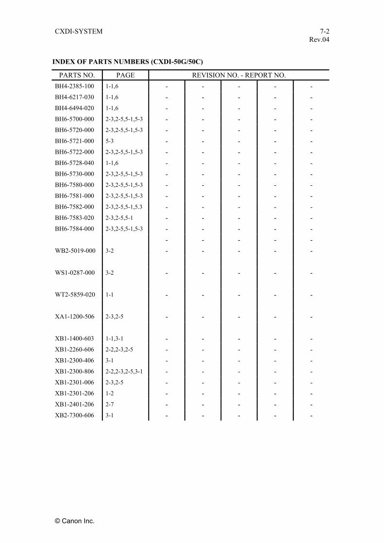
CXDI-SYSTEM 7-2 Rev.04
© Canon Inc.
INDEX OF PARTS NUMBERS (CXDI-50G/50C)
PARTS NO. PAGE REVISION NO. - REPORT NO. BH4-2385-100 1-1,6 - - - - - BH4-6217-030 1-1,6 - - - - - BH4-6494-020 1-1,6 - - - - - BH6-5700-000 2-3,2-5,5-1,5-3 - - - - - BH6-5720-000 2-3,2-5,5-1,5-3 - - - - - BH6-5721-000 5-3 - - - - - BH6-5722-000 2-3,2-5,5-1,5-3 - - - - - BH6-5728-040 1-1,6 - - - - - BH6-5730-000 2-3,2-5,5-1,5-3 - - - - - BH6-7580-000 2-3,2-5,5-1,5-3 - - - - - BH6-7581-000 2-3,2-5,5-1,5-3 - - - - - BH6-7582-000 2-3,2-5,5-1,5.3 - - - - - BH6-7583-020 2-3,2-5,5-1 - - - - - BH6-7584-000 2-3,2-5,5-1,5-3 - - - - - - - - - - WB2-5019-000 3-2 - - - - - WS1-0287-000 3-2 - - - - - WT2-5859-020 1-1 - - - - - XA1-1200-506 2-3,2-5 - - - - - XB1-1400-603 1-1,3-1 - - - - - XB1-2260-606 2-2,2-3,2-5 - - - - - XB1-2300-406 3-1 - - - - - XB1-2300-806 2-2,2-3,2-5,3-1 - - - - - XB1-2301-006 2-3,2-5 - - - - - XB1-2301-206 1-2 - - - - - XB1-2401-206 2-7 - - - - - XB2-7300-606 3-1 - - - - -
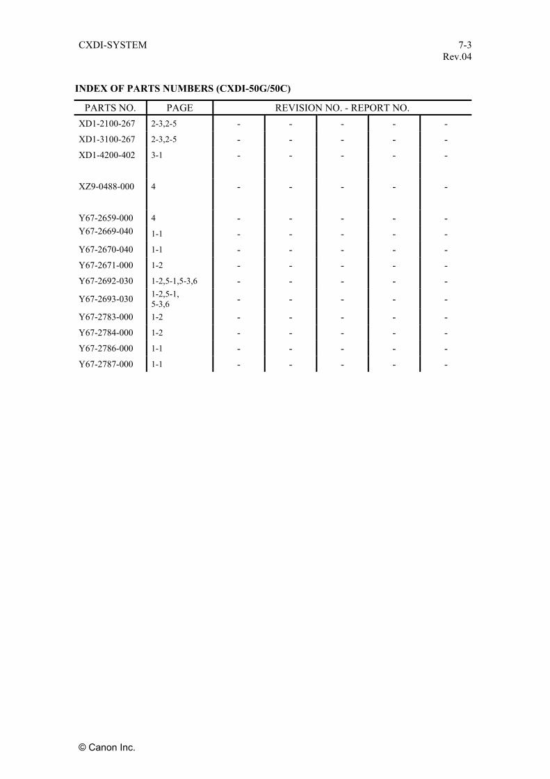
CXDI-SYSTEM 7-3 Rev.04
INDEX OF PARTS NUMBERS (CXDI-50G/50C)
PARTS NO. PAGE REVISION NO. - REPORT NO. XD1-2100-267 2-3,2-5 - - - - - XD1-3100-267 2-3,2-5 - - - - - XD1-4200-402 3-1 - - - - - XZ9-0488-000 4 - - - - - Y67-2659-000 4 - - - - - Y67-2669-040 1-1 - - - - - Y67-2670-040 1-1 - - - - - Y67-2671-000 1-2 - - - - - Y67-2692-030 1-2,5-1,5-3,6 - - - - -
Y67-2693-030 1-2,5-1, 5-3,6 - - - - -
Y67-2783-000 1-2 - - - - - Y67-2784-000 1-2 - - - - - Y67-2786-000 1-1 - - - - - Y67-2787-000 1-1 - - - - -
© Canon Inc.


CCXXDDII--5500GG // 5500CC
CCaannoonn IInncc.. JJaappaann CCooppyyrriigghhtt ((CC)) CCaannoonn IInncc.. MMeeddiiccaall TTeecchhnniiccaall SSeerrvviiccee DDeepptt.. AAllll rriigghhttss RReesseerrvveedd..
66.. TTrroouubblleesshhoooottiinngg
PPrriinntteedd bbyy CCaannoonn IInncc.. FFeebb.. 22000066 RReevv..0033


Content
1 Gathering Information about Problems ................................................................................. 1
2 How to back up and recover the system ................................................................................ 3
6. Troubleshooting
1
11 GGaatthheerriinngg IInnffoorrmmaattiioonn aabboouutt PPrroobblleemmss 1.1 Outline It is recommended to replace the whole unit (50G/50C, OPU, power box, C3S) if any problem occurs at the customer’s site in order to reduce the downtime of the system.
It is desirable to have the bad unit brought back and repaired. (Although it depends on the kind of the problem.)
This section explains about the information (log file) required to know what has occurred and what to be done.
1.2 Probable problems - System connection failure and condition setting failure during installation
- Electrical and mechanical system failure, malfunctioning, bad image, noise, and communication error
- Software and specifications problem
1.3 Required information 1.3.1 When Dr. Watson Error occurs Gather information when:
- Communication error related to Dr. Watson occurred between the OPU and the CXDI, resulting in CXDI application failure
- Display on the OPU freezes and cannot be recovered
(1) Environmental information (such as version of the CXDI host program, composition of hardware and optional software)
(2) Dr. Watson log
C:\Documents and Settings\All Users\Application Data\Microsoft\Drwatson\drwts32.log
(3) Event viewer system log
C:\WINDOWS\system32\config\SysEvent.Evt
(4) The whole D:\Ccr folder
Depending on the timing the error has occurred, images may be saved in a folder before dtstore. In this case, copy dttmp and dtque folder.
1.3.2 When Error occurs Information required differs according to whether optional module (such as DMW, generator communication module, etc.) is used or not.
(1) Log files and information required no matter optional module is used or not
1) How the system is used at the customer’s site (System composition)
2) Version of CXDI host program
3) Error message and code
4) All the INI files directly under CCR folder

6. Troubleshooting
2
5) All the BodyParts folders
All of the above five items are necessary to see how the CXDI is set. If the problem has occurred in the CXDI, the information is required to have the problem occur again.
6) opu3.log and opu3_YYYYMMDDHHMMSS.log
When file size exceeds 1 MB, opu3.log makes a new “opu3.log” with a different name in “opu3_YYYYMMDDHHMMSS.log” when the system is restarted.
Ten history files in the past will be saved.
Because a new log is made when the file size is large, log at the time the error occurred may be in a file other than “opu3.log”.
Since location of the log cannot be checked at the customer’s site, please be sure to collect not only the opu3.log but all the history files.
7) syslog
8) Dr. Watson log
9) Event viewer system log
(2) Required log files and information according to the used optional module
Please also gather the following files and information other than those indicated in (1).
(2-1) DMW
1) chmwm.ini
2) ccMax_ws.ini
chmwm.ini/ccMax_ws.ini will be collected automatically when all the INI files directly under CCR folder are collected.
3) chmwm.log
4) DICOM conformance statement of RIS
(2-2) Generator communication module
1) cgbig3.ini
2) StrTable.ini
StrTable.ini will be collected automatically when all the INI files directly under CCR folder are collected.
3) Character string (such as error code) that is displayed in the error dialog box
1.3.3 When image is bad 1) How the system is used at the customer’s site (System composition)
2) Version of CXDI host program
3) D:\ccr
4) Bad image and the images taken before and after it

6. Troubleshooting
3
22 HHooww ttoo bbaacckk uupp aanndd rreeccoovveerr tthhee ssyysstteemm [Objective]
This document describes how to back up and recover the system.
[Technical Description]
There are two system backup methods as follow:
The recovery method required depends on the way the system crashes.
Backup method
A) Backup using floppy disks
B) Backup using a hard drive
1. Backup method A) Backup method using floppy disks
The network settings configured in each installation site and the customized body part settings are stored in each ini file.
All the ini files are stored on a floppy disk when starting up the control PC.
The system has a feature that stores the latest ini files on the floppy disk at the system startup by updating the ini files with modifications users made while using the system.
B) Backup method using a hard drive
The control PC has no feature that mirrors all the files including the OS to other hard drives.
Therefore, to be ready for hard drive crashes, we recommend that you add another hard drive when installing the system, in order to copy the software between the hard drives using Ghost or Drive Copy, which are available on the market.
This should be conducted at the final installation stage (just before delivery to users).
As an alternative, you can also provide a hard drive that contains the OS (before activation) and drivers in case of hard drive crashes.
2. Recovery method 2.1 When problems occur in a Ccr software ini file The system can be recovered to the last environment status just before the system was used by users when problems*1 occur in d:\Ccr software other than the OS. *1 When the setting data or files are damaged
In this case,
The recovery can be made by overwriting ini files stored on the floppy disk to d:\ccr.

6. Troubleshooting
4
2.2 When problems occur in Ccr software When problems occur in files other than ini files for d: \Ccr software other than the OS, recovery can be accomplished by adding or replacing the relevant files if you can identify the defective files. Recover Ccr with the following procedure if you cannot identify the defective files:
1) Copy d: \ccr to a different directory or laptop computer.
2) Delete d: \ccr, and then newly install the CXDI software. (Note)
(Note) The same version of the software must be installed.
3) Copy the following files in Ccr that were copied in Step 1) to d: \ccr
\dtstore (captured images)
\Logs
\White.dcm
\defpix#.dat
\xxxxxx.dp
4) Newly install the optional software (DMW/Gen.communication) if you are using it.
5) Copy to overwrite all the ini files in d: \Ccr stored on the floppy disk in order to recover the user’s environment.
6) Perform the settings again that are described in the “Control PC serial number” and “Setting the imaging unit identification and the number of connecting units” in this manual “Setting Procedures”.
2.3 When the hard drive crashes Recover the system using the following method when the hard drive crashes.
1) Replace the crashed hard drive with the hard drive provided in item B above, “Backup method using a hard drive”.
* Copy \Ccr from the original hard drive to the new hard drive when the D drive in the crashed hard drive is in a normal state (a problem case caused by the OS).
Note: Perform Step 2 after upgrading if the CXDI version you are using is newer than that in the hard drive provided by copying from hard drive to hard drive during system installation.
(Files such as Str.ini are not compatible when the CXDI version is different.)
* When the hard drive has crashed mechanically, proceed to Step 2 and subsequent steps.
2) After replacement, copy to overwrite all the ini files stored on the floppy disk to d:\ccr in order to recover the user’s environment.
Note that images captured by users cannot be inherited in this case.
Note: Calibration is required when the system has been used for over one year.
Note: Perform Step 2 after upgrade if the CXDI version you are using is newer than that in the hard drive provided by copying from hard drive to hard drive during system installation.
(Files such as Str.ini are not compatible when the CXDI version is different.)
2.4 When problems occur in driver software When drivers such as the touch panel driver are damaged, reinstall the appropriate drivers by referring to “C3S Service Manual”.
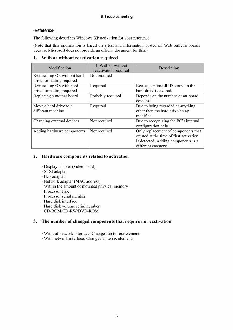
6. Troubleshooting
5
-Reference- The following describes Windows XP activation for your reference.
(Note that this information is based on a test and information posted on Web bulletin boards because Microsoft does not provide an official document for this.)
1. With or without reactivation required
Modification 1. With or without reactivation required Description
Reinstalling OS without hard drive formatting required
Not required
Reinstalling OS with hard drive formatting required
Required Because an install ID stored in the hard drive is cleared.
Replacing a mother board Probably required Depends on the number of on-board devices.
Move a hard drive to a different machine
Required Due to being regarded as anything other than the hard drive being modified.
Changing external devices Not required Due to recognizing the PC’s internal configuration only.
Adding hardware components Not required Only replacement of components that existed at the time of first activation is detected. Adding components is a different category.
2. Hardware components related to activation
· Display adapter (video board) · SCSI adapter · IDE adapter · Network adapter (MAC address) · Within the amount of mounted physical memory · Processor type · Processor serial number · Hard disk interface · Hard disk volume serial number · CD-ROM/CD-RW/DVD-ROM
3. The number of changed components that require no reactivation
· Without network interface: Changes up to four elements · With network interface: Changes up to six elements

CCXXDDII--5500GG // 5500CC
CCaannoonn IInncc.. JJaappaann CCooppyyrriigghhtt ((CC)) CCaannoonn IInncc.. MMeeddiiccaall TTeecchhnniiccaall SSeerrvviiccee DDeepptt.. AAllll rriigghhttss RReesseerrvveedd..
77.. SSeerrvviiccee MMaannuuaall RReeppoorrtt
PPrriinntteedd bbyy CCaannoonn IInncc.. FFeebb.. 22000066 RReevv..0033