creek st iom - superior boiler...creek st boiler manual 6 revision 2013.07 the warranty...
TRANSCRIPT
CREEK ST BOILER MANUAL Condensing Water Boiler
300 - 2000 MBtu/Hr. Gas
Superior Boiler Works, Inc. 3524 E. 4th Avenue
Hutchinson, KS 67501 (620) 662-6693
www.superiorboiler.com
Manufactured in the USA to the ASME boiler and pressure vessel code.
Creek ST Boiler Manual
2 Revision 2013.07
ContentsGENERAL ........................................................................................................................................................... 5
Documents Unique to your boiler .................................................................................................................... 5
Supplementary Manuals: .................................................................................................................................. 5
Acronyms, Definitions, Standards, & Sources ................................................................................................. 6
Introduction to safety ........................................................................................................................................ 7
Approvals & Recordkeeping ............................................................................................................................ 8
1 BOILER SIGNAGE ............................................................................................................................................ 10
2 BOILER COMPONENT IDENTIFICATION .................................................................................................... 18
2.1 Boiler Specifications and Dimensions .......................................................................................................... 19
2.2 Cross Sections .............................................................................................................................................. 25
2.3 Typical Instrumentation Spools .................................................................................................................... 26
2.4 Burner Mount ............................................................................................................................................... 27
2.5 Gas Train ...................................................................................................................................................... 27
2.6 Standard Junction Box Location ................................................................................................................... 28
2.7 Miscellaneous Images .................................................................................................................................. 29
3 SPECIFICATIONS ............................................................................................................................................. 30
4 BOILER INSTALLATION ................................................................................................................................. 31
4.1 Receiving the Boiler ..................................................................................................................................... 31
4.2 Unloading the Boiler-Burner Unit ................................................................................................................ 31
4.3 Boiler Unloading Instructions ...................................................................................................................... 32
4.4 The Boiler Room .......................................................................................................................................... 33
4.5 Extended Storage Procedure for Boilers not yet installed. ........................................................................... 33
4.6 Casing Panel Installation .............................................................................................................................. 34
4.7 Installation of Loose Shipped Items ............................................................................................................. 34
4.8 Electrical Installation .................................................................................................................................... 35
4.9 Miscellaneous Installation Guidelines .......................................................................................................... 36
4.10 Furnace Drawer .......................................................................................................................................... 36
4.11 Boiler Stack Connection ............................................................................................................................. 36
4.12 Vent Material Selection .............................................................................................................................. 37
5 Plumbing your Boiler .......................................................................................................................................... 38
5.1 Fuel Supply & Connections .......................................................................................................................... 38
5.2 Boiler Connections, General ......................................................................................................................... 38
5.3 Water Connections ....................................................................................................................................... 38
5.4 Hot Water Boilers Supply & Return Connections ........................................................................................ 38
5.5 Drains ........................................................................................................................................................... 39

Creek ST Boiler Manual
Revision 2013.07 3
5.6 Drain connections ......................................................................................................................................... 39
5.7 Condensate Drain Connection ...................................................................................................................... 39
5.8 Safety relief valves (SRV) ............................................................................................................................ 39
5.9 SRV Discharge Piping .................................................................................................................................. 40
6 Boiler Start-up ..................................................................................................................................................... 41
6.1 Operating Data .............................................................................................................................................. 41
6.2 Start-up Guidelines ....................................................................................................................................... 41
6.3 Tools & Gauges ............................................................................................................................................ 42
6.4 Fuel Guidelines ............................................................................................................................................. 42
6.5 Cleaning and Filling a New Boiler ............................................................................................................... 42
6.6 Firing a New Boiler ...................................................................................................................................... 43
6.7 Boil-out Procedure ........................................................................................................................................ 43
6.8 Start-up of Hot Water Boilers ....................................................................................................................... 44
6.9 Good practice recommendations for hot water boilers ................................................................................. 45
6.10 Guidelines for hot water boiler heating system. ......................................................................................... 45
7 Operation ............................................................................................................................................................. 46
7.1 Safety Relief Valves ..................................................................................................................................... 46
7.2 Gauges .......................................................................................................................................................... 47
7.2.1 Pressure Gauges ..................................................................................................................................... 47
7.2.2 Pressure Gauge range ............................................................................................................................ 47
7.2.3 Pressure Gauge Accuracy ...................................................................................................................... 47
7.2.4 Pressure gauge calibration ..................................................................................................................... 48
7.2.5 Temperature gauges ............................................................................................................................... 48
7.2.6 Pressure or altitude gauges .................................................................................................................... 48
7.2.7 Stack thermometers ............................................................................................................................... 48
7.3 Temperature controls .................................................................................................................................... 48
7.3.1 High limit: ............................................................................................................................................. 48
7.3.2 Operator: ................................................................................................................................................ 48
7.3.3 Firing rate control: ................................................................................................................................. 48
7.4 Maintenance on temperature limiting controls ............................................................................................. 48
7.5 Example of control set point adjustment procedure ..................................................................................... 49
7.6 Water level controls ...................................................................................................................................... 49
7.6.1 Electric probe type low-water fuel cutoffs ............................................................................................ 49
7.6.2 Low-water fuel cutoff and water feeder maintenance ........................................................................... 49
7.6.3 Low-water cutoff (LWCO) .................................................................................................................... 49
7.7 Water level operations .................................................................................................................................. 50
Creek ST Boiler Manual
4 Revision 2013.07
7.8 Water Treatment ........................................................................................................................................... 50
7.8.1 Heating boilers ....................................................................................................................................... 51
7.8.2 Water treatment guidelines .................................................................................................................... 51
7.9 Access openings and burner mount .............................................................................................................. 52
7.9.1 Burner mount ......................................................................................................................................... 52
7.9.2 Door Aperture ........................................................................................................................................ 52
8 MAINTENANCE ................................................................................................................................................ 53
8.1 Spare Parts. ................................................................................................................................................... 53
8.2 Maintenance schedule .................................................................................................................................. 53
8.2.1 Daily procedure ..................................................................................................................................... 54
8.2.2 Weekly procedure. ................................................................................................................................. 54
8.2.3 Monthly procedure ................................................................................................................................ 55
8.2.4 Semi-Annual procedure ......................................................................................................................... 56
8.2.5 Annual procedure .................................................................................................................................. 57
8.3 Detailed Empty inspection............................................................................................................................ 58
8.4 Limit control tests ......................................................................................................................................... 59
8.4.1 High & Low gas pressure switch limit test & adjustment ..................................................................... 59
8.4.2 Electrical Limit Controls. ...................................................................................................................... 60
9 TROUBLESHOOTING ...................................................................................................................................... 61
10 Out of service operations ................................................................................................................................... 62
10.1 Shutdown .................................................................................................................................................... 62
10.2 Boiler taken out of service .......................................................................................................................... 62
10.3 Boiler laid up dry ........................................................................................................................................ 62
10.4 Boiler laid up wet procedure ...................................................................................................................... 63
10.5 Re-commissioning ...................................................................................................................................... 63
Creek ST Boiler Manual
Revision 2013.07 5
GENERAL The boilers of the CREEK ST series have a horizontal through-flame combustion chamber and a vertical condensing section of a special design in stainless steel type AISI 316 Ti. These elements are immersed in water contained in a horizontal boiler drum with a vertical column to which the system inlet and outlet connections are fitted. These boilers reach very high efficiency levels (nearly 108% referred to the Lower Calorific Value LCV). The flue gases not only are released at a temperature little higher than that of the system return water but also a large part of the water vapor contained in the flue gases is condensed. This recovers the latent heat of condensation. The particular flame path (through the combustion chamber without inversion) limits as much as possible the formation of Nitrogen Oxides (NOx) that form when the flame remains at high temperature in the combustion chamber for long periods. The CREEK ST series boilers place no limit on the return water temperature. However the boilers reach the highest performance when used with floor panel heating systems in which the return temperature is lower than 135 °F. At higher temperatures, condensation does not occur and so the recovery of the latent heat contained in the water vapor, present in the flue gas, is impossible. The efficiency of the boiler remains high in any case (97%) even with traditional high-temperature heating systems (t 175/150 °F). Thank you for purchasing a Superior Boiler Works Inc. (SBW) product. This manual is for the CREEK ST line of boilers. READ AND SAVE THESE INSTRUCTIONS FOR REFERENCE. These manual and associated documents are to be kept with the boiler and in legible condition for the life of the boiler. This manual will refer to the burner’s manual when appropriate. A double asterisk (**) is used to indicate that your burner manual should also be checked for information on the topic being covered unless otherwise noted. In addition to the boiler and burner working together, there are controls, switches, valves, and other components on your boiler assembled specific to each end user. A list of exact components and information about them is appended to this manual. All of these documents and devices work together to safely operate your boiler. Documents Unique to your boiler There are many Superior Boiler Works Inc. (SBW) Documents created unique to each boiler. These documents are appended to this manual either directly before or after this structured manual.
Document # of pages Page #/Location Cover page with your information Pages Zero/First Specification sheets 4 Appendix 1 Ratings and dimension drawing 1 Appendix 2 Recommended spare parts 1 to 3 Appendix 3 List of component manuals 1 to 4 Appendix 4 ASME data reports 1 to 12 pages Appendix 6 Panel Casing installation 7 Appendix 7 Firetest report (if tested) 0 to 4 Appendix 8 MSDS Information (if supplied) 0 to 9 Appendix 9 Miscellaneous unique paperwork for this boiler Any Appendix 10 Wiring drawing(s) can be large format Last Supplementary Manuals: This manual is intended to be used in conjunction with other documents. Burner manual and manuals that comes with the burner. Appendix 11 Manuals for every major component supplied with the boiler. Appendix 12
Creek ST Boiler Manual
6 Revision 2013.07
The Warranty validation/Start-up report information sheet must be filled out and return to SBW within three weeks of when the burner is first turned on and within two months of shipment of boiler to maintain your warranty. Also note that boil-out procedures, a slow initial warm up, and proper water treatment are required to maintain your warranty.
WARNING The improper installation, adjustment, service,
maintenance, or operation of this equipment can result in fire, explosion, series injury, or death.
Acronyms, Definitions, Standards, & Sources SBW: Superior Boiler Works Inc. ASME: American Society of Mechanical Engineers ASME CSD-1: Controls and Safety Devices for Automatically Fired Boilers BPVC: ASME boiler and pressure vessel code. Section IV: Portion of BPVC that applies to water boilers not exceeding 160 PSIG or 250°F and Steam boilers not exceeding 15 PSIG Heating boiler: hot water boiler Water boiler: Boiler that supplies hot water LWCO: Low-water cutoff, or Low-water fuel cutoffs Aux LWCO: Auxiliary Low water cutoff LWCO mark: Vertical position on boiler where the primary LWCO operates ANSI: American National Standards Institute 150# class: ANSI standard of flanged piping connections, NPS: Nominal pipe size NPT: National pipe thread (tapered) MAWP: Maximum allowable working pressure Set point: A specific value of pressure or temperature used in a control where it will switch on or off. Aquastat: Water temperature control device BoHP: Boiler horse power is equivalent to 33,475 Btu/Hr. PSI: Pounds per square inch PSIG: PSI gauge reading. In. WC: Inches of water column. Units of pressure where one (1) PSI = 28 In. WC (28” WC) UL: Underwriters Laboratories Inc. UL Mark: Signage on the boiler designating UL approval UL 795: Commercial-Industrial Gas Heating Equipment UL 353: Limit Controls cUL: Verification to Canadian Requirements by Underwriters Laboratories Inc. CSA: Canadian Standards Association CSA 3. 1-77-CAN1: Industrial and Commercial Gas-Fire Package Boilers (Reaffirmed 2011) CSA 22.1: Canadian Electrical Code Part 1 CSA B149: Natural Gas & Propane Code NFPA: National Fire Protection Agency NFPA 54: National Fuel Gas Code NFPA 70: National Electric Code, AKA: NEC IFGC: International Fuel Gas Code R&D drawing: Ratings and Dimensions drawings. AKA: General Arrangement.
Creek ST Boiler Manual
Revision 2013.07 7
Introduction to safety
Refer to this manual and the burner manual. For assistance or additional information consult a qualified installer, service agency, or fuel supplier as appropriate.
DO NOT STORE OR USE GASOLINE OR ANY OTHER FLAMMABLE LIQUIDS IN THE VICINITY OF THIS OR ANY OTHER APPLIANCE. DO NOT USE GASOLINE, CRANKCASE DRAININGS, OR ANY OIL CONTAINING GASOLINE. NEVER BURN GARBAGE OR PAPER IN THE UNIT, AND NEVER LEAVE COMBUSTABLE MATERIAL AROUND IT.
All personnel involved with the startup, maintenance, or adjustment of this boiler must read and understand the entire contents of this manual prior to any startup or adjustment being made to the boiler and related components. Installation and service must be performed by a qualified installer, service agency, or the fuel supplier. Safe and reliable operation is dependent to a large extent upon the skill and attentiveness of the operator and of the maintenance personnel. Operating skill implies the following: Knowledge of fundamentals Familiarity with equipment Suitable background of training and experience Full and effective use should be made of manufacturer's instruction books on operation and maintenance. Of special importance are written procedures prepared expressly for each installation by the manufacturers' service engineers and qualified personnel from the operating organization before and during the commissioning period. These procedures are based on actual experience and often include invaluable information on what the equipment is expected to do. Limitations critical to safe and reliable operations are also given. Control systems vary in complexity from computer control to manual operation. Regardless of the type of system used, the operators should be thoroughly trained so that they can maintain safe and continuous operation during changeover from automatic to manual control as well as to continue operation by manual control if the automatic systems are out of service. The operator should have instrumentation at the point of manual operation to permit him to be aware of operating conditions at all times. Regularly scheduled auto-manual changeover, manual operation, and emergency drills to prevent loss of these skills are recommended. What to do if you smell gas: Do not try to light any appliance Do not touch any electrical switch Do not use any phone in your building Immediately call your gas supplier from a neighbor’s phone Follow the gas supplier’s instructions If you cannot reach your gas supplier, call the fire department.
NOTICE! This is used to point out warranty issues
WARNING The improper installation, adjustment, service,
maintenance, or operation of this equipment can result in fire, explosion, series injury, or death. NOTICE!
Creek ST Boiler Manual
8 Revision 2013.07
Approvals & Recordkeeping All SBW boilers are designed, manufactured, and stamped to the ASME BPVC. Refer to the signage information section to determine the approvals that have been applied to your boiler. THE INSTALLATION OF THIS BOILER SHALL BE IN ACCORDANCE WITH THE REGULATIONS OF AUTHORITIES HAVING JURISDICTION. BOILERS SHALL BE OPERATED BY QUALIFIED PERSONNEL. BOILERS SHALL BE INSTALLED AND SERVICED BY QUALIFIED PERSONNEL ONLY. Boilers intended for Canadian markets, refer to the following regulations as applicable: The equipment shall be installed in accordance with the current Installation Code for Gas Burning Appliances and Equipment, CSA B149, and applicable Provincial Regulations for the class; which should be carefully followed in all cases. Authorities having jurisdiction should be consulted before installations are made. Wiring shall be in accordance with the CSA 22.1 Canadian Electrical Cod, Part I. The installation of the unit shall be in accordance with the regulations of the authorities having jurisdiction Boilers intended for American markets, refer to the following regulations as applicable: NFPA54: National Fuel Gas Code NFPA70: National Electrical Code IFGC: International Fuel Gas Code All drawings, wiring diagrams, schematic arrangements, manufacturers’ descriptive literature, spare parts lists, and written operating instruction should be kept permanently in the boiler room or other suitable location so it will be available to those who operate and maintain the boiler. Where space permits, drawing and diagrams should be framed or sealed in plastic and hung adjacent to the related equipment. Other materials should be assembled and enclosed in a suitable binder. When change or additions are made, the data and drawings should be revised accordingly. READ AND SAVE THESE INSTRUCTIONS FOR REFERENCE. Some states and municipalities require licensing or certification of personnel who operate or maintain heating equipment. Also, some authorities require posting of inspection certificates in the boiler room. The supervisor in charge of a given installation should make sure such requirements are met.
Creek ST Boiler Manual
Revision 2013.07 9
GENERAL WARNINGS Each generator is provided with a data plate that can be found in the envelope with the boiler documents. The plate lists: Serial number or identification code; Rated thermal output; Furnace thermal output; Types of fuels that can be used; Maximum operating pressure. A manufacturer's certificate is also provided which certifies the hydraulic test pressure. The installation must be performed in compliance with the regulations in force by professionally qualified personnel. The term “professionally qualified personnel” means persons with specific technical skills in the sector of heating system components. Incorrect installation may cause damage to persons, animals or objects for which the manufacturer cannot be held responsible. At the first start up, all regulation and control devices positioned on the control panel should be checked for efficiency. The guarantee shall be valid only upon compliance with the instruction given in this manual. IMPORTANT: This boiler has been designed to heat hot water to a temperature lower than the boiling point of water at atmospheric pressure and must be connected to a heating plant and/or a domestic hot water plant within the limits of the boiler performance and output.
WARNING THE BOILER MAY ONLY BE INSTALLED IN A ROOM WHICH COMPLIES WITH THE APPROPRIATE VENTILATION REQUIREMENTS. READ THE INSTALLATION AND USER INSTRUCTION BEFORE INSTALLING AND LIGHTING THE BOILER.
Creek ST Boiler Manual
10 Revision 2013.07
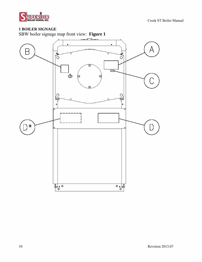
1 BOILER SIGNAGE SBW boiler signage map front view: Figure 1
Creek ST Boiler Manual
Revision 2013.07 11
The Serial No. or National Board No. is useful when contacting SBW for spare parts or support.
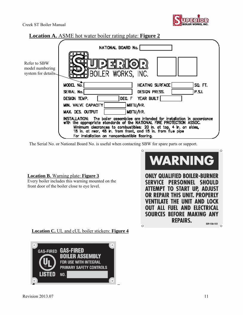
Location A. ASME hot water boiler rating plate: Figure 2
Refer to SBW model numbering system for details
Location B. Warning plate: Figure 3 Every boiler includes this warning mounted on the front door of the boiler close to eye level.
Location C. UL and cUL boiler stickers: Figure 4
Creek ST Boiler Manual
12 Revision 2013.07
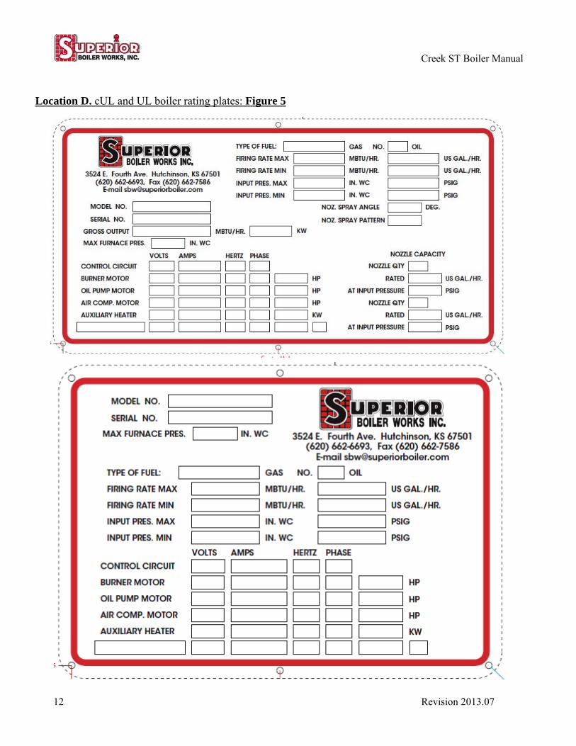
Location D. cUL and UL boiler rating plates: Figure 5
Creek ST Boiler Manual
Revision 2013.07 13
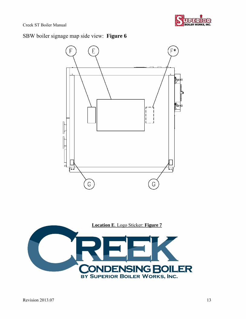
SBW boiler signage map side view: Figure 6
Location E. Logo Sticker: Figure 7
Creek ST Boiler Manual
14 Revision 2013.07
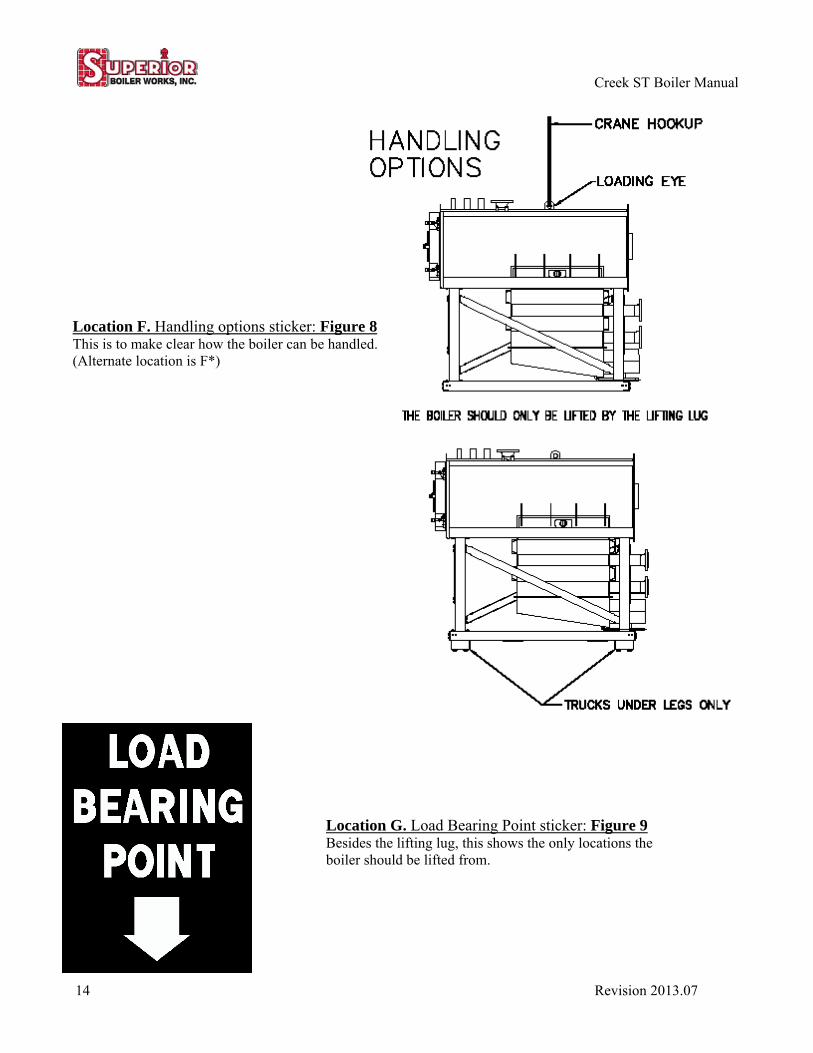
Location G. Load Bearing Point sticker: Figure 9 Besides the lifting lug, this shows the only locations the boiler should be lifted from.
Location F. Handling options sticker: Figure 8 This is to make clear how the boiler can be handled. (Alternate location is F*)
Creek ST Boiler Manual
Revision 2013.07 15
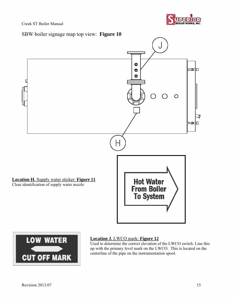
SBW boiler signage map top view: Figure 10
Location J. LWCO mark: Figure 12 Used to determine the correct elevation of the LWCO switch. Line this up with the primary level mark on the LWCO. This is located on the centerline of the pipe on the instrumentation spool.
Location H. Supply water sticker: Figure 11 Clear identification of supply water nozzle

Creek ST Boiler Manual
16 Revision 2013.07
SBW boiler signage map rear view: Figure 13
Creek ST Boiler Manual
Revision 2013.07 17
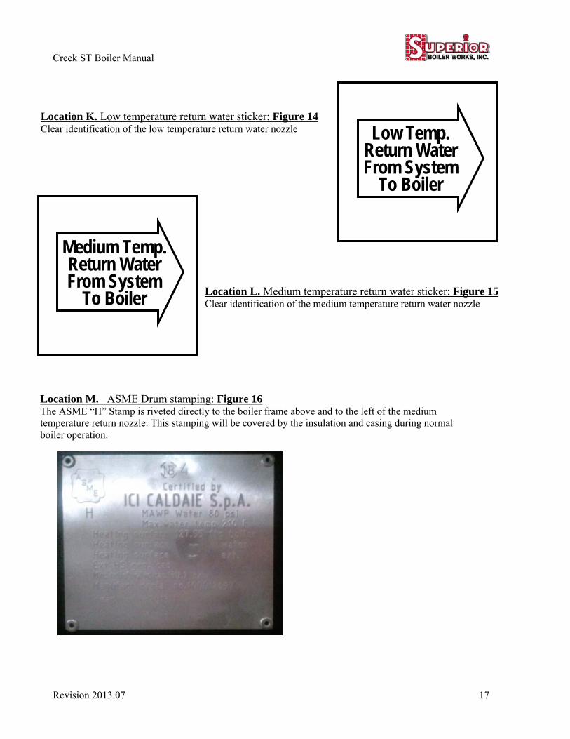
Location M. ASME Drum stamping: Figure 16 The ASME “H” Stamp is riveted directly to the boiler frame above and to the left of the medium temperature return nozzle. This stamping will be covered by the insulation and casing during normal boiler operation.
Low Temp. Return Water From System
To Boiler
Medium Temp. Return Water From System
To Boiler
Location K. Low temperature return water sticker: Figure 14 Clear identification of the low temperature return water nozzle
Location L. Medium temperature return water sticker: Figure 15Clear identification of the medium temperature return water nozzle
Creek ST Boiler Manual
18 Revision 2013.07
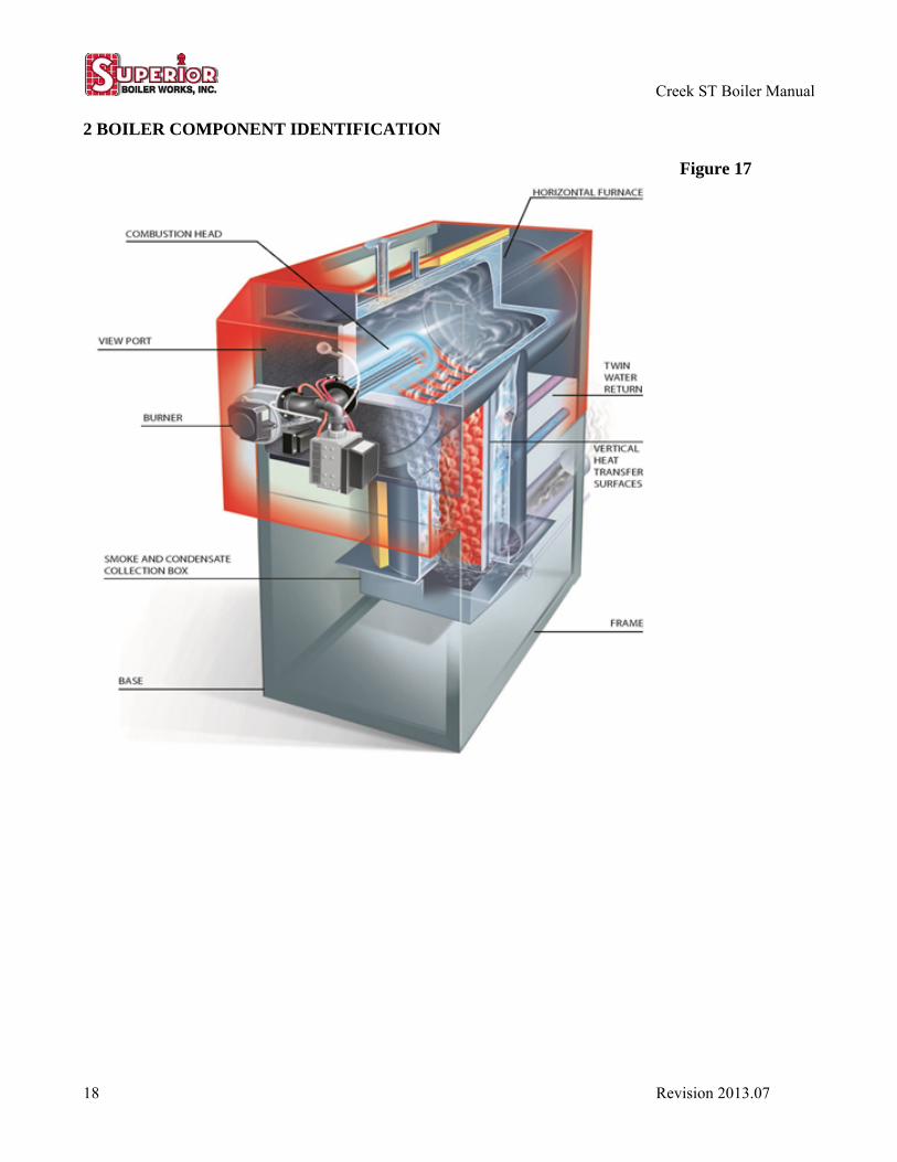
2 BOILER COMPONENT IDENTIFICATION
Figure 17
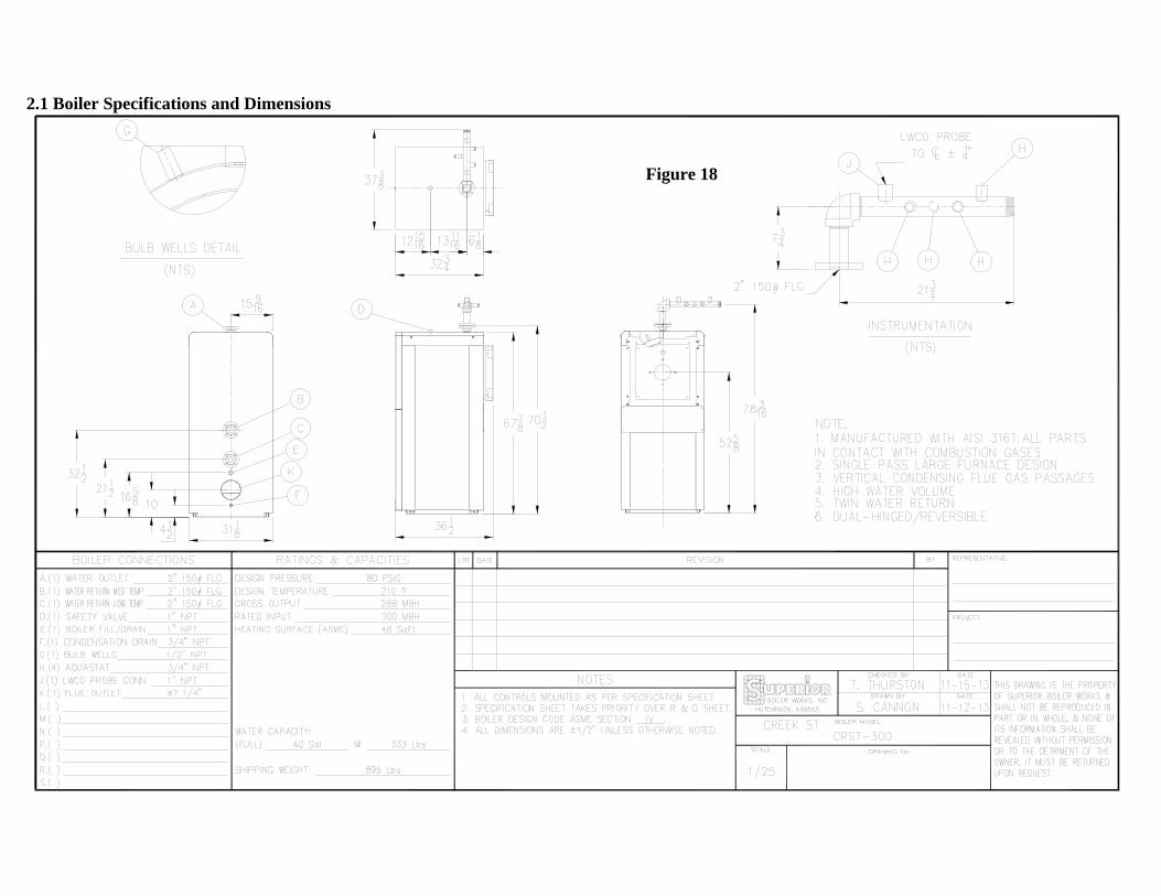
2.1 Boiler Specifications and Dimensions
Figure 18

Figure 19
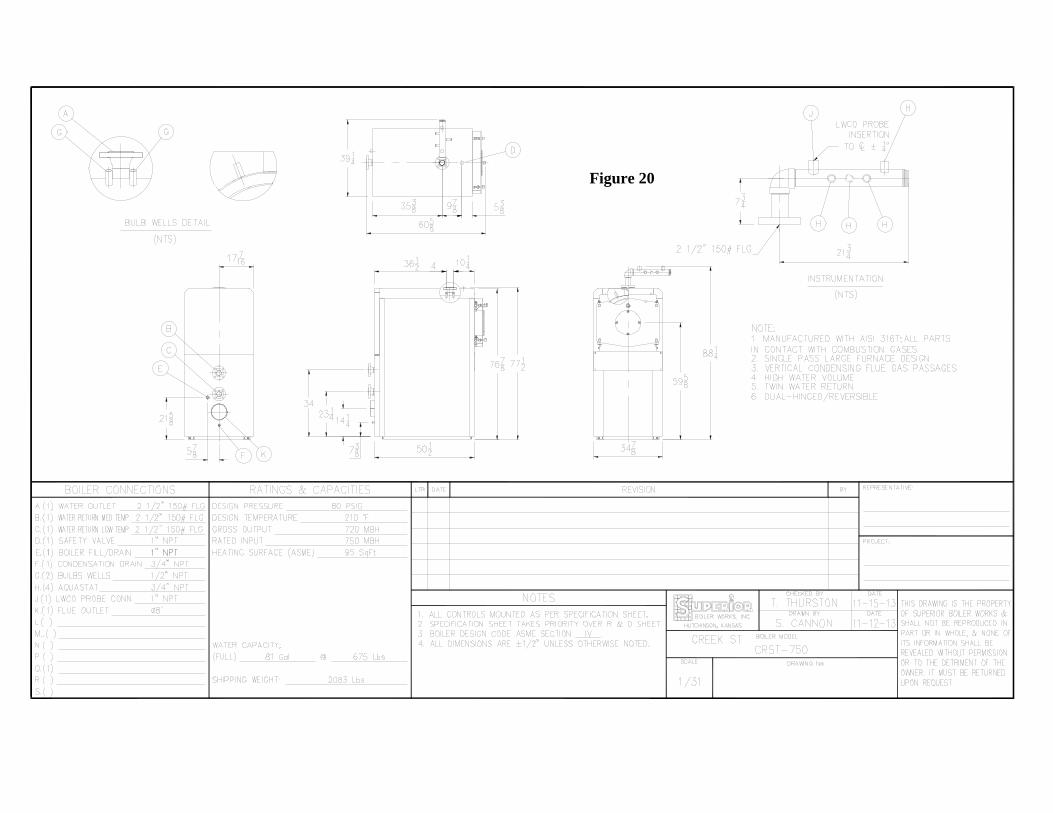
Figure 20
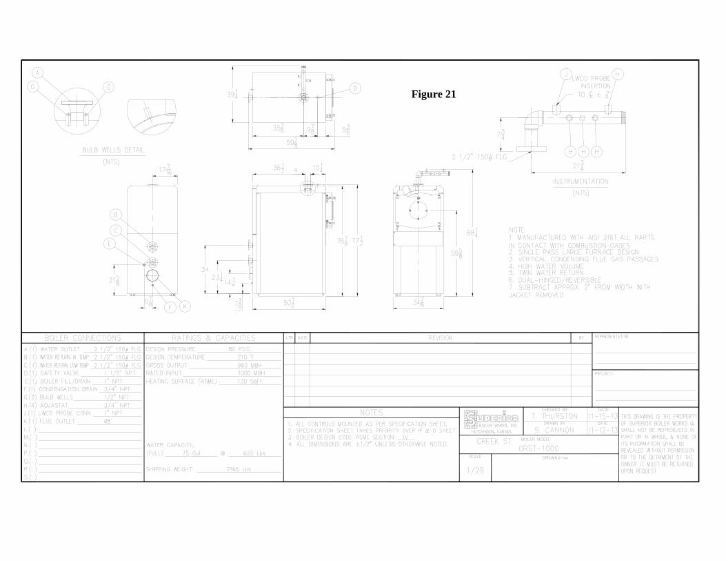
Figure 21
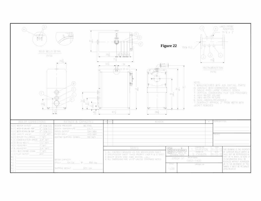
Figure 22
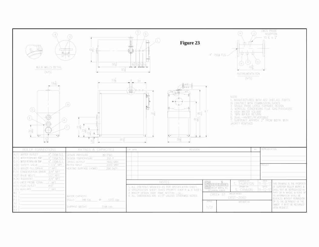
Figure 23
Creek ST Boiler Manual
Revision 2013.07 25
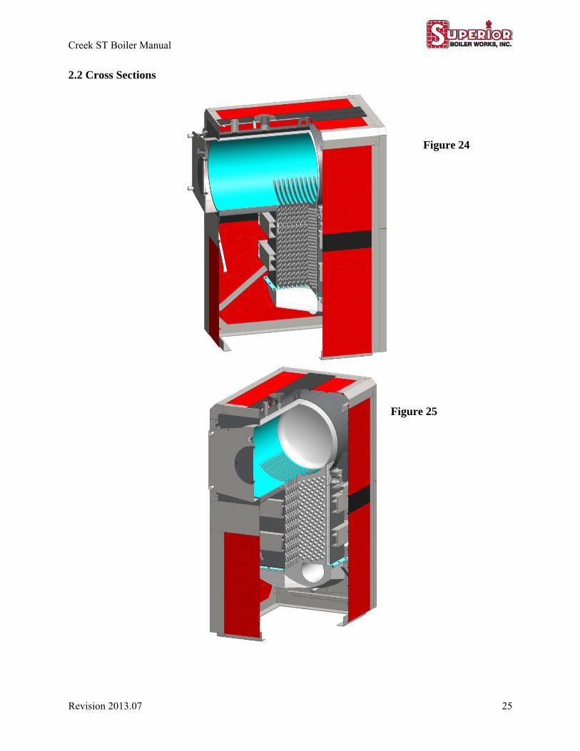
2.2 Cross Sections
Figure 24
Figure 25
Creek ST Boiler Manual
26 Revision 2013.07
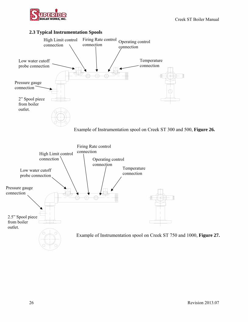
2.3 Typical Instrumentation Spools
Low water cutoff probe connection
2” Spool piece from boiler outlet.
Example of Instrumentation spool on Creek ST 300 and 500, Figure 26.
High Limit control connection
Firing Rate control connection
Operating control connection
Temperature connection
Example of Instrumentation spool on Creek ST 750 and 1000, Figure 27.
2.5” Spool piece from boiler outlet.
Low water cutoff probe connection
High Limit control connection
Firing Rate control connection
Operating control connection
Temperature connection
Pressure gauge connection
Pressure gauge connection
Creek ST Boiler Manual
Revision 2013.07 27
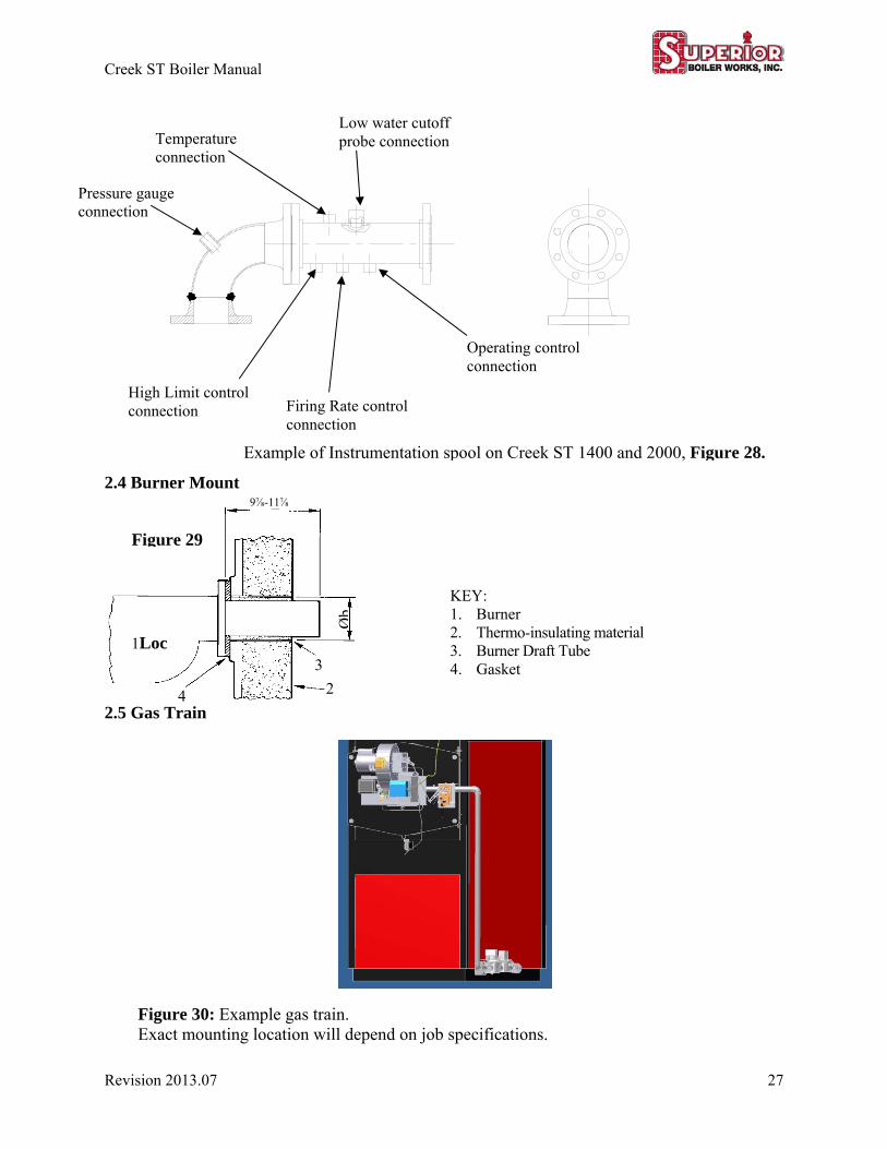
2.4 Burner Mount
2.5 Gas Train
1Loc
4
3
2
Figure 29
KEY: 1. Burner 2. Thermo-insulating material 3. Burner Draft Tube 4. Gasket
Øb
Example of Instrumentation spool on Creek ST 1400 and 2000, Figure 28.
Temperature connection
Low water cutoff probe connection
High Limit control connection Firing Rate control
connection
Operating control connection
9⅞-11⅞
Pressure gauge connection
Figure 30: Example gas train. Exact mounting location will depend on job specifications.
Creek ST Boiler Manual
28 Revision 2013.07
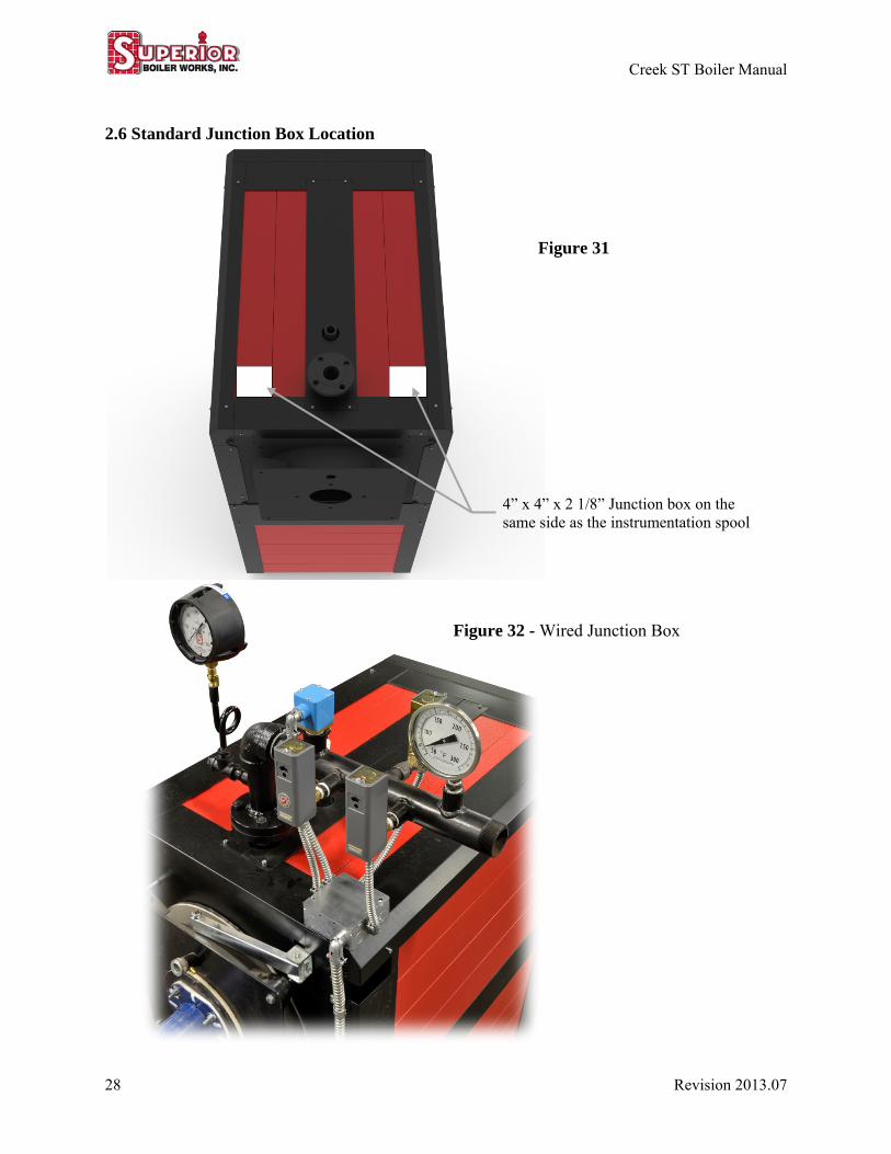
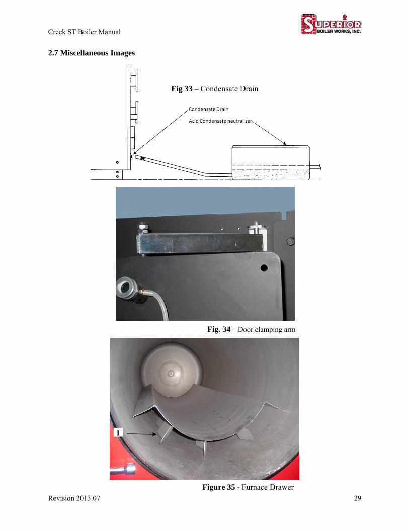
2.6 Standard Junction Box Location
Figure 31
Figure 32 - Wired Junction Box
4” x 4” x 2 1/8” Junction box on the same side as the instrumentation spool
Creek ST Boiler Manual
Revision 2013.07 29
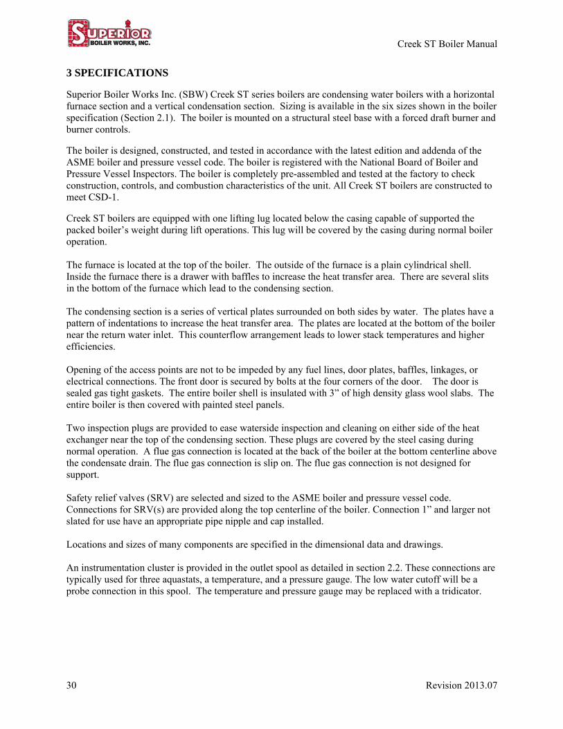
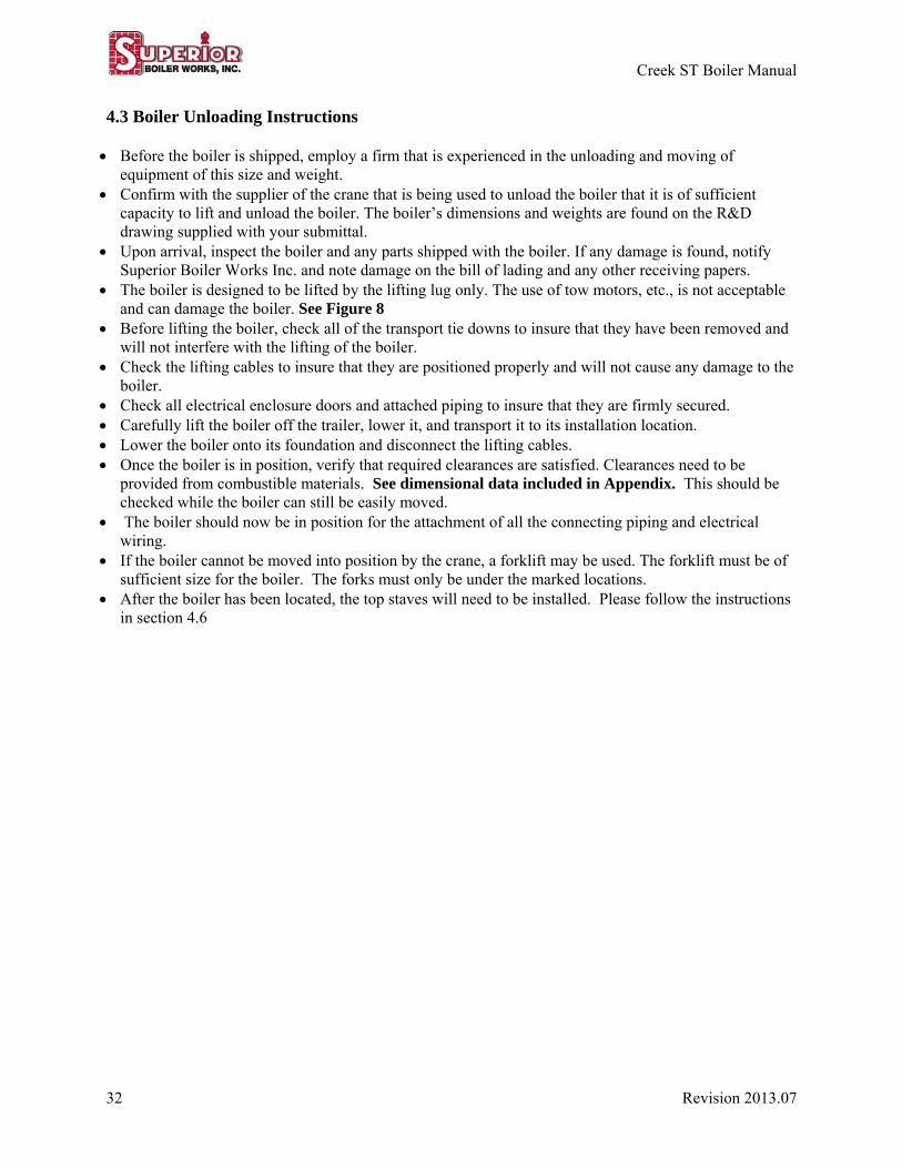
2.7 Miscellaneous Images
Fig. 34 – Door clamping arm
1
Figure 35 - Furnace Drawer
Fig 33 – Condensate Drain
Creek ST Boiler Manual
30 Revision 2013.07
3 SPECIFICATIONS Superior Boiler Works Inc. (SBW) Creek ST series boilers are condensing water boilers with a horizontal furnace section and a vertical condensation section. Sizing is available in the six sizes shown in the boiler specification (Section 2.1). The boiler is mounted on a structural steel base with a forced draft burner and burner controls. The boiler is designed, constructed, and tested in accordance with the latest edition and addenda of the ASME boiler and pressure vessel code. The boiler is registered with the National Board of Boiler and Pressure Vessel Inspectors. The boiler is completely pre-assembled and tested at the factory to check construction, controls, and combustion characteristics of the unit. All Creek ST boilers are constructed to meet CSD-1. Creek ST boilers are equipped with one lifting lug located below the casing capable of supported the packed boiler’s weight during lift operations. This lug will be covered by the casing during normal boiler operation. The furnace is located at the top of the boiler. The outside of the furnace is a plain cylindrical shell. Inside the furnace there is a drawer with baffles to increase the heat transfer area. There are several slits in the bottom of the furnace which lead to the condensing section. The condensing section is a series of vertical plates surrounded on both sides by water. The plates have a pattern of indentations to increase the heat transfer area. The plates are located at the bottom of the boiler near the return water inlet. This counterflow arrangement leads to lower stack temperatures and higher efficiencies. Opening of the access points are not to be impeded by any fuel lines, door plates, baffles, linkages, or electrical connections. The front door is secured by bolts at the four corners of the door. The door is sealed gas tight gaskets. The entire boiler shell is insulated with 3” of high density glass wool slabs. The entire boiler is then covered with painted steel panels. Two inspection plugs are provided to ease waterside inspection and cleaning on either side of the heat exchanger near the top of the condensing section. These plugs are covered by the steel casing during normal operation. A flue gas connection is located at the back of the boiler at the bottom centerline above the condensate drain. The flue gas connection is slip on. The flue gas connection is not designed for support. Safety relief valves (SRV) are selected and sized to the ASME boiler and pressure vessel code. Connections for SRV(s) are provided along the top centerline of the boiler. Connection 1” and larger not slated for use have an appropriate pipe nipple and cap installed. Locations and sizes of many components are specified in the dimensional data and drawings. An instrumentation cluster is provided in the outlet spool as detailed in section 2.2. These connections are typically used for three aquastats, a temperature, and a pressure gauge. The low water cutoff will be a probe connection in this spool. The temperature and pressure gauge may be replaced with a tridicator.

Creek ST Boiler Manual
Revision 2013.07 31
The High limit, Operating, and Firing rate controls are installed as individual components in the boiler outlet spool instrumentation cluster. Stop valves are not to be installed between the boiler and any of these controls. These controls occupy three of the connections of the instrumentation cluster with aquastats. The Firing rate controller can be replaced with a temperature sensor that is incorporated into the burners controls. The operator and firing rate controls can be incorporated into the same device. The water supply nozzles are ANSI class 150# flange. Creek ST boilers come with a medium and a low temperature water return nozzle along the centerline above the flue gas outlet. If only one nozzle is used always use the low temperature return. Recirculation pump connections and re-circulating pumps may be added to one or both sides of the boiler to isolate the boiler from the hot water system and reduce temperature differential across the boiler. The boiler shall have a drain connection. 4 BOILER INSTALLATION 4.1 Receiving the Boiler During the construction of your new boiler, over one hundred (100) separate inspections were made of the unit. These inspections started with your unit’s engineering drawings and ended with the signing of the bill of lading by the freight carrier. These inspections were made by our Quality Control Department and our Insurance Inspection Agency. At the time the freight carrier signed the bill of lading at our factory, he acknowledged that the unit was received by him in an undamaged condition. It is good practice for you, prior to signing the freight carrier’s delivery receipt, to examine your boiler in detail to be sure that the unit has not been damaged in transit. If damage is evident, make a notation on the freight bill of the damage and file a claim against the carrier for the cost of replacement or repair. In the event your boiler-burner unit should have sustained concealed damage (damage which is not outwardly evident), you have up to fifteen (15) days after receipt of the unit to file a claim covering repair or replacement of the concealed damage. Most of our units are shipped with certain fragile and easily damaged parts packaged in a separate box. The freight bill will describe the number of pieces shipped. Be sure that all pieces noted on the freight bill are received. Boilers are typically shipped with the main boiler burner package assembled with fuel train(s), mounted switches, and wiring that is practical before placement. Electrical components are wrapped in plastic and the boilers internals are closed off from the elements. The shipped condition is only intended to protect the boiler from weather during transport, not additional long term storage. Some parts are shipped loose with the boiler. Boil out chemicals, if purchased from SBW, are shipped separately. 4.2 Unloading the Boiler-Burner Unit Your new boiler-burner unit is equipped a single lifting lug, located on the top of the boiler along the centerline. This is to be used for unloading. A crane is the best means of unloading and setting the new unit in place. A forklift can also be used to unload and set the boiler. When a forklift is used, be certain that it is only lifted from the designated points. DO NOT USE A LIFTING CABLE AROUND THE UNIT. See Figures 8 & 9
Creek ST Boiler Manual
32 Revision 2013.07
4.3 Boiler Unloading Instructions Before the boiler is shipped, employ a firm that is experienced in the unloading and moving of
equipment of this size and weight. Confirm with the supplier of the crane that is being used to unload the boiler that it is of sufficient
capacity to lift and unload the boiler. The boiler’s dimensions and weights are found on the R&D drawing supplied with your submittal.
Upon arrival, inspect the boiler and any parts shipped with the boiler. If any damage is found, notify Superior Boiler Works Inc. and note damage on the bill of lading and any other receiving papers.
The boiler is designed to be lifted by the lifting lug only. The use of tow motors, etc., is not acceptable and can damage the boiler. See Figure 8
Before lifting the boiler, check all of the transport tie downs to insure that they have been removed and will not interfere with the lifting of the boiler.
Check the lifting cables to insure that they are positioned properly and will not cause any damage to the boiler.
Check all electrical enclosure doors and attached piping to insure that they are firmly secured. Carefully lift the boiler off the trailer, lower it, and transport it to its installation location. Lower the boiler onto its foundation and disconnect the lifting cables. Once the boiler is in position, verify that required clearances are satisfied. Clearances need to be
provided from combustible materials. See dimensional data included in Appendix. This should be checked while the boiler can still be easily moved.
The boiler should now be in position for the attachment of all the connecting piping and electrical wiring.
If the boiler cannot be moved into position by the crane, a forklift may be used. The forklift must be of sufficient size for the boiler. The forks must only be under the marked locations.
After the boiler has been located, the top staves will need to be installed. Please follow the instructions in section 4.6
Creek ST Boiler Manual
Revision 2013.07 33
4.4 The Boiler Room Local building codes and insurance requirements usually dictate the type of construction and the material to be used in the boiler room. The boiler room floor should be non-combustible and of adequate strength to support the weight of the boiler full of water. The boiler room floor should include a floor drain See the “Drains” section. It is advisable to provide, when possible, wall and floor surfaces that permit the use of water hoses. Space should be provided in the boiler room to accommodate boiler water treatment equipment and any other equipment that may be required in the boiler room. Adequate space should be provided around each boiler to permit cleaning and inspection of all piping supplied with the boiler. After the boiler has been set in place, ensure it is level. Fresh & Ventilation Air The boiler room must have an adequate air supply to permit clean, safe combustion and to minimize soot formation. An unobstructed air opening should be provided. It may be sized on the basis of 1 sq in. free area per 1000 Btu/hr. maximum fuel input of the combined burners located in the boiler room, or as specified in NFPA 54 or IFGC as applicable to your installation. The boiler room air supply openings must be kept clear at all times. Also review the ventilation requirement of your burner. Lighting The boiler room should be well lit and it should have adequate emergency lighting for use in case of power failure. If a flashlight is used for this purpose, it should be maintained in usable condition and it should be protected against removal from the boiler room. 4.5 Extended Storage Procedure for Boilers not yet installed.
If a newly delivered boiler is to be placed outdoors for more than two weeks, the following steps shall be taken:
The boiler should be placed on crossties under the legs, preferably on a flat surface of concrete or asphalt.
Make certain that any moisture from weather has been removed Remove the inspection plugs and place desiccant inside. The electrical enclosures and panels will also require desiccant to protect against condensation. A
handful’s worth of desiccant in a cardboard lid will do. Close the unit up tight to exclude all moisture and air. Desiccant should be checked weekly. When the desiccant has changed color, it is used up. Replace as
required. The entire boiler should be covered with a tarp, with emphasis on protection for the gas train, air
compressor, low water cutoff, junction boxes, burner control panels, and boiler control panels. For the water side of a boiler, SBW recommends a desiccant product called boiler lizards. These tubes of desiccant can be opened and placed in the water side of a boiler. The boiler lizards can remain in the water side of the boiler to be dissolved by water. The desiccant and tubular bags are water soluble; dissolving the first time water is added to the boiler. Desiccant placed in other locations should be removed prior to placing the boiler in service. Even if the extended storage is inside, this extended storage procedure is recommended.
NOTICE!
Creek ST Boiler Manual
34 Revision 2013.07
4.6 Casing Panel Installation The Creek ST boiler is shipped with the top casing panels removed so that the lifting lug is exposed. After the boiler is set, these remaining panels should be installed. The panels will need to be secured by screws on each end. For more details on panel installation see the installation details in the Appendix. 4.7 Installation of Loose Shipped Items After the final staves are attached, loose shipped items can be installed and the boiler can be connected to your systems. It is preferable to delay installation of any items with glass like gauges until after the piping has been completed to avoid glass breakage. Items that typically ship loose are: Touch up paint Safety relief valve(s) Pressure gauge Water temperature gauge or tridicator Stack thermometer Gaskets and bolts between any hot water outlet parts Many components like gauges and gaskets will have their own manuals. Please refer to the appropriate documentation for installation. At least one small parts box will be supplied with your boiler for small items like pressure gauges, thermometers, and any other small loose items you ordered. Larger and heavier items are typically shipped on pallets. For water boilers, an appropriate pressure and temperature gage or a tridicator is provided. Install them in the instrumentation cluster as instructed by the manufacturer’s cut sheet. See Figure 26-28 An appropriate stack thermometer is provided. Install into a 1/2” coupling on the instrumentation spool. The safety relief valve(s) shall be installed at connections provided on the top of the boiler. Often this takes place after the boil-out procedure. The safety relief valve(s) provided for your boilers are documented in the ASME data reports provided with this manual. See the safety relief valve installation section
Creek ST Boiler Manual
Revision 2013.07 35
4.8 Electrical Installation
ELECTRICAL INSTALLATION SHALL BE IN ACCORDANCE WITH THE REGULATIONS OF AUTHORITIES HAVING JURISDICTION. THE FOLLOWING CODES SHALL BE
FOLLOWED AS APPLICABLE. CSA 22.1: CANADIAN ELECTRICAL CODE PART 1, NFPA 70: NATIONAL ELECTRIC CODE (NEC)
A wiring diagram for the boiler and burner will be inside the burner control panel. The wiring diagram, in conjunction with this manual and O&M manuals for the burner and electrical components, should provide an electrician with everything required to properly install the electrical components. Before installing, modifying, or servicing system, the main electrical disconnect switch must be in the OFF position. There may be more than 1(one) disconnect switch. Lock out and tag switch with a suitable warning label.
The exact configurations of electrical panels vary. The most common configuration is at the front of the boiler on the same side as the instrumentation spool. See Figures 31 & 32. The junction box will be secured to the panels by sheet metal screws. Additional small junction boxes are used when needed. If for repair purposes wiring is run to any probes, that wiring shall be sufficient for 150°F. Grounding of some components is conducted through the boiler and the mounting of burner to the boiler. Electrical power requirements are listed on placards for the respective components. Wiring from any boiler mounted controls and any fuel train controls is pulled into the burner control panel. Wiring for sensors tends to be specific to the manufacture of the burner management system. If maintenance is performed on this wiring, ensure the appropriate wire is used. Wires are mounted on terminal strips for ease of trouble shooting and maintenance. Power for Electrically Operated Controls All controls are powered with a potential of 150 V or lower with one side grounded. A separate equipment ground conductor should be brought to the control panel frame with ground continuity assured to the fuel valve. All operating coils of control devices should be connected to the neutral side of the control circuit, and all control limit switches or contacts should be in the ungrounded (hot) side of the control circuit. If an isolating transformer is used, it should be bonded to the control panel frame. The equipment ground is not required when the isolating transformer is used. Do not fuse control transformers above their rated current value because these devices are current limiting and an oversize fuse may not blow under short circuit conditions. Remote Emergency Shutdown Switches A manually operated remote shutdown switch or circuit breaker shall be located just outside the boiler room door and marked for easy identification. Consideration should also be given to the type and location of the switch to safeguard against tampering. If the boiler room door is on the building exterior, the switch should be located just inside the door. If there is more than one door to the boiler room, there should be a switch located at each door. Where a boiler is located indoors in a facility and not in a boiler room, a remote emergency shutdown switch shall be located within 50 feet of the boiler along the primary egress route from the boiler area. The installer shall be responsible to install the remote emergency shutdown switch(s) and to verify that it is suitably marked.
WARNING The improper installation, adjustment, service,
maintenance, or operation of this equipment can result in fire, explosion, series injury, or death.
Creek ST Boiler Manual
36 Revision 2013.07
4.9 Miscellaneous Installation Guidelines Software & Safety Programming controls, when used, shall provide proper sequencing of the above controls to insure that all conditions necessary for proper burner operation are satisfied. Included in a programmed control are pre-purge and post-purge cycles to remove accumulated gases. Flame Safeguard When installation is complete, safety controls will stop fuel flow in the cases of ignition failure, main flame interruption, mechanical draft failure, and circuit failure as appropriate for your installation. The controls on the burner and boilers are designed to prevent fuel flow when any of the boiler conditions are outside intended limits of pressure, temperature, and water level as is appropriate for your system. Venting of Gas Controls Venting of gas controls should conform to recognized installation standards. It is best to check with the authorities having jurisdiction to determine your specific requirements. 4.10 Furnace Drawer A drawer has been fitted inside the furnace in order to increase thermal exchange and efficiency of the boiler. If removed, it is necessary to refit it making sure that the open side with fin supports (labeled “1” in figure 35) must stay in the front part close to the door in order to allow a complete reverse flame inside the furnace. The distance from the front edge of the furnace must correspond to the dimension indicated on the baffle warning label. 4.11 Boiler Stack Connection A flue gas connection is located at the bottom centerline at the back, just above the condensate drain of your boiler. The stack connection is slip-on. The flue gas connection is not designed for support. The breaching and chimney shall at minimum be the size of the boilers stack connector. The exhaust must be pitched a minimum of a 1/4 inch per foot back to the boiler to allow drainage of condensate. When installing a boiler where the exhaust is tied into other systems, a professional should be consulted. INSTALLATION AND MAINTENANCE OF THE STACK SHALL BE IN COMPLIANCE WITH THE AUTHORITIES HAVING JURISDICTION. Furnace pressure: The pressure drop between the burner and the stack connector at high fire. Draft: The difference between the “stack effect” of your stack and the pressure drop of your stack. Stack effect: Flue gasses are hotter & buoyant compared to ambient air. Both draft & furnace pressure are measured at the stack connector. However it should be evident that the two terms have completely different meanings. This is typically measured with a manometer (Supplied by others). Your new boiler-burner unit is supplied with a forced draft burner capable of supplying all the air for combustion when operating at reasonable amount of draft. The boiler shall be connected to a vent having
Creek ST Boiler Manual
Revision 2013.07 37
sufficient draft at all times to ensure safe and proper operations of the unit. For details on the relationship between draft and burner operation, refer to your burner manual or consult a professional. The furnace pressure (negative gauge value) should be between 0.03” and 0.6” WC at the stack connector. Stack installation and adjustment are the responsibility of the installer. The installation of your venting system should be conducted by a professional installer who can properly balance the draft of your system with the tuning of your burner. Draft can dramatically impact the adjustment of your burner on a seasonal basis. Draft values and draft control vary depending on the configuration of your stack, weather conditions, firing rate of your boiler, and many other variables. The stack draft must not impair the stability of the flame and should be checked before installation. 4.12 Vent Material Selection SBW recommends the use category IV UL 1738 listed ducting systems for positive pressure condensing boilers installed by a professional contractor. The ducts should be double wall construction with at least one inch between the liner (inside wall) and a shell (outside wall). Single wall construction can be used, but the heat losses, potential fire hazards, and risks to people become problematic. A properly insulated ducting system minimizes heat losses that can vary draft due to changing weather conditions and minimize heat risks to personnel. Please see UL 1738 for more information. Materials:
Liner for gas: stainless steel AL294C The shell can be made from any corrosion resistant steel including: stainless 304, stainless 316, or
aluminized carbon. Specific selection is determined upon your environment, preferences, and local practices.
Thickness:
Liner should be 20 gauge. Shells can vary from 26 gauge to 18 gauge depending on diameter, construction style, and structural
installation choices. The UL listing process specifics an amount of incidental contact protection that is a good recommended standard.
Clearance:
Single wall ducts require up to 18” of clearance from any flammable material Each manufacture of ducting will have a rating that specifies a require clearance to flammable
material ranging from one (1) to six (6) inches.
WARNING The flue gas temperatures produced by CREEK ST boilers are considerably lower than in the case of non-condensing boilers, and have therefore very high relative humidity. For these reasons the chimney must be completely watertight, able to withstand corrosion attack by acid condensate, and adequately heat-insulated to guarantee sufficient draft.
Creek ST Boiler Manual
38 Revision 2013.07
5 Plumbing your Boiler
THE INSTALLATION OF THE UNIT SHALL BE IN ACCORDANCE WITH THE REGULATION OF THE AUTHORITIES HAVING JURISDICTION. INSTALLATIONS SHALL BE IN ACCORDANCE WITH CSA
B149, NFPA 54, AND IFGC AS APPROPRIATE.
5.1 Fuel Supply & Connections Gas piping shall be of adequate pressure at capacity for your applications in accordance with NFPA 54. UL/cUL listed boilers have the required fuel pressures and flow rates on the rating plate. 5.2 Boiler Connections, General
The configuration of the supplied piping is documented on your R&D drawing. The piping on a boiler should be kept leak proof. A small leak, if allowed to continue, soon becomes a
major problem. Discharge from all blowdowns, safety relief valves, and venting shall be plumbed to a safe point of
discharge. Please consult the authorities having jurisdiction to determine your discharge requirements. All plumbing installation of the boiler shall be in accordance with the regulation of the authorities
having jurisdiction. Provisions shall be made for the expansion and contraction of hot water mains connected to boilers so
there will be no undue strain transmitted to the boilers. 5.3 Water Connections
A proper and convenient water fill connection should be installed and provisions should be made to prevent boiler water from back-feeding into the service water supply. Provision should also be made in every boiler room for a convenient water supply which can be used to flush out the boiler and to clean the boiler room floor. 5.4 Hot Water Boilers Supply & Return Connections Makeup water shall only be introduced to the boiler though the water inlet. The makeup water pipe shall be provided with a check valve or a backflow preventer containing a check valve near the boiler and a stop valve or cock between the check valve and the boiler or between the check valve and the return piping system. Some jurisdictions may require installation of a backflow preventer in the feedwater connection. Stop valve(s) shall be placed in the supply and return pipe connections of a single hot water heating boiler installation to permit draining the boiler without emptying the system. When stop valves over two (2”) inches are used, they shall be of the outside and screw yoke rising spindle type, or of such other type as to indicate at a distance by the position of its spindle or other operating mechanism whether it is closed or open. The wheel may be carried either on the yoke or attached to the spindle. If the valve is of the plug cock type, it shall be fitted with a slow opening mechanism and an indicating device. The plug shall be held in place by a guard or gland. The design pressure of all valves used in water headers should equal or exceed the design pressure of the boilers they are attached to.
WARNING The improper installation, adjustment, service,
maintenance, or operation of this equipment can result in fire, explosion, series injury, or death.
Creek ST Boiler Manual
Revision 2013.07 39
5.5 Drains Unobstructed floor drains, properly located in the boiler room, will facilitate proper cleaning of the boiler room. Floor drains that are used infrequently should have water poured into them periodically to prevent the entrance of sewer gasses and odors. If there is a possibility of freezing, an environmentally safe antifreeze mixture should be used in the drain traps. Drains receiving blowdown water should be connected to the sanitary sewer by way of an acceptable blowdown tank, separator, or air gap that will allow the blowdown water to cool to at least 140°F and reduce the pressure to 5 PSIG or less. 5.6 Drain connections The discharge piping shall be full size to the point of discharge. The minimum pressure rating of valves and cocks used for drain purposes shall be at least equal to the pressure stamped on the boiler but in no case less than 30 psi. The temperature rating of such valves and cocks shall not be less than 250°F. 5.7 Condensate Drain Connection The condensate drain is located at the rear of the boiler below the flue connection. Slope the condensate tubing down and away from the boiler into a drain or condensate neutralizing filter. Do not expose the condensate line to freezing temperatures. A condensate removal pump is required if boiler is below the drain. When installing a condensate pump, select one approved for use with condensing boilers and furnaces. The pump should have an overflow switch to prevent property damage from condensate spillage. The switch should be wired to the auxiliary device proving switch terminals on the low voltage connection board. Condensate from the CREEK ST will be slightly acidic (typically with a pH from 3 to 5). Install a neutralizing filter if required by local codes. If the boiler is not supplied with acid condensate neutralizer, a siphon loop must be fitted on the condensate drain in order to avoid flue gas leakage. 5.8 Safety relief valves (SRV) See the operation instructions for more details on SRV SRV need to be installed so that no significant loads are placed on the outlet. Testing and occasional weeping can create condensate. Drip pan elbows are recommended to handle these issues during installation. Safety valves are shipped loose because they are vital to safe operation and can be damaged during transport. SRV are installed to prevent operation of the boiler above maximum allowable working pressure. It is good practice to manually open the safety relief valves on your boiler monthly. This is done by lifting and releasing the handle provided on the valve. Refer to the maintenance section for details on use of these valves.
Creek ST Boiler Manual
40 Revision 2013.07
5.9 SRV Discharge Piping A discharge pipe shall be used. Its internal cross sectional area shall be not less than the full area of the valve outlet or of the total of the valve outlets discharged therein. It shall be as short and straight as possible and so arranged as to avoid undue stress on the valve or valves. A union may be installed in the discharge piping close to the valve outlet. When an elbow is placed on a safety or safety relief valve discharge pipe, it shall be located close to the valve outlet downstream of the union. The discharge from safety relief valves shall be so arranged as to minimize the danger of scalding attendants. The safety or safety relief valve discharge shall be piped away from the boiler to a safe point of discharge and there shall be provisions made for properly draining the piping. The size and arrangement of discharge piping shall be independent of other discharge piping and such that any pressure that may exist or develop will not reduce the relieving capacity of the relieving devices below that required to protect the boiler. The discharge piping should be supported so that loads (piping weights and dynamic forces during operation) transmitted to the relief valves are minimized. The weight supported by the valve should not exceed the weight of a short elbow and drip pan or comparable weight of a direct connected free hanging discharge pipe. Installations requiring long discharge piping runs should not have those discharge piping runs directly connected to the valve. The valve manufacturer should be consulted if the weight to be loaded on a valve outlet exceeds a short elbow with a drip pan.
Creek ST Boiler Manual
Revision 2013.07 41
6 Boiler Start-up The design, manufacture, and assembly of your new unit is the result of years of engineering work and field testing. It is a sophisticated piece of equipment to be serviced only by qualified people. If you don't already have a qualified operator, we recommend that you contact your SBW representative for the name of experienced service personnel in your area. Each burner can vary in details, but the following should help outline the steps involved with first time startup. The following section and your burner manual will provide many details for safe first time startup.
All Personnel involved with the startup, maintenance, or adjustment of this boiler must read and understand the entire contents of this manual prior to any startup or adjustment made to the boiler and related components.
Installation and service must be performed by a qualified installer, service agency or the fuel supplier.
6.1 Operating Data Whenever a new boiler is placed in service, operating data should be recorded, compared to predicted performance, and saved for future reference. This information is extremely valuable for diagnosing problems if abnormal operation occurs. Record all operating parameters such as pressures, temperatures, flows, draft losses, motor amps, turbine speeds, damper positions, and interlock set points. This data assists operators to spot trends and take corrective action. Maintenance plans can be made by comparing the routine logs to the base data. For operating data to be meaningful, the instruments and controls must be well maintained and properly calibrated. A new or relocated power boiler should not be put into operation until it has been inspected by an Authorized Inspector for the authorities having jurisdiction or insurance company and the required certificates have been issued. 6.2 Start-up Guidelines Start-up and testing of new unit is a SERIOUS matter. Take time to become familiar with the equipment you will be working with. Review the burner manual. Review the wiring diagrams, operating sequence, piping schematics, installation drawings, and any
other pertinent information for the particular pieces of equipment. Before applying electrical power to the unit, check all electrical connections to ensure they are secure
and properly connected Before applying fuel to the unit, check all piping to ensure it is arranged per the drawings and that all
connections are tight DO NOT START THE BURNER UNLESS ALL CLEANOUT DOORS ARE SECURED IN PLACE.
WARNING The improper installation, adjustment, service,
maintenance, or operation of this equipment can result in fire, explosion, series injury, or death.
Creek ST Boiler Manual
42 Revision 2013.07
6.3 Tools & Gauges Before you begin, check that the following tools & gauges are installed or available:
Stack thermometer, 50-500°F Temperature gauge appropriate for your size of boiler Flue gas analyzer U-tube inclined type manometer to measure stack draft and furnace pressure U-tube or calibrated gauge for gas pressure Multi-meter Meter to measure flame signal A stack velocity meter, if you need to verify stack flow 6.4 Fuel Guidelines
Do not attempt to relight the pilot or start burner with the combustion chamber full of gas or with a very hot combustion chamber.
Do not use gasoline, crankcase drainings, or any oil containing gasoline. NEVER BURN GARBAGE OR PAPER IN THE UNIT, AND NEVER LEAVE COMBUSTIBLE
MATERIAL AROUND IT. Review all safety guidelines 6.5 Cleaning and Filling a New Boiler
Prior to starting a new boiler an inspection should be made to insure that no foreign matter such as tools, equipment, rags, etc., is left in the boiler. Before putting water into a new boiler, make certain that the firing equipment is in operating condition to the extent that this is possible without actually lighting a fire in the empty boiler. This is necessary because raw water must be boiled [or heated to at least 180°F)] promptly after it is introduced into the boiler in order to drive off the dissolved gases, which might otherwise corrode the boiler. In a hot water heating system, the boiler and entire system (other than the expansion tank) must be full of water for satisfactory operation. The red, or fixed, hand on the combination altitude gage and thermometer is normally set to indicate the amount of pressure required to fill the system with cold water. Water should be added to the system until the black hand registers the same or more than the red hand. To insure that the system is full, water should come out of all air vents when opened. The water must enter the system as slowly as possible, and in proportion to the rate of air purge from the components involved. In the case of a system with a closed expansion tank, water is injected until the pressure gauge reaches the static pressure for the tank. Then proceed to heat the water to the maximum allowed plant temperature. During this operation, the air in the system purges from the automatic or manual air separators fitted to the system. On completion of the air purge, bring the pressure to the set value and close the manual and/or automatic water supply valve.
Creek ST Boiler Manual
Revision 2013.07 43
6.6 Firing a New Boiler
Commissioning and firing a new boiler is to be conducted by your installer. This process is beyond the scope of this manual. This is to be conducted by qualified personnel only. Refer to the burner manual for more information about starting up the burner.
When tuning the flame in your new boiler, the flame should not be allowed to impinge upon the back of the furnace. If the boiler is tuned with flame continuously impinging upon the back of the furnace the warranty is void. Also see the boil out instructions and start up procedures for details on firing the boiler for the first time.
6.7 Boil-out Procedure
All new boilers must be boiled out or Superior Boiler Works will void the warranty! Before introducing the boil-out chemicals to any drain system, check local environmental regulations to ensure you are in compliance.
It is necessary to clean the inside of the new boiler of oil and grease. Failure to remove these materials will result in your unit foaming, priming, and pulling over. These contaminants must be removed to provide clean heat transfer surfaces. Before boil-out procedures may begin, the burner must be ready for firing and the operator must be familiar with the procedure outlined under burner operation. SBT-710 is the chemical recommended for the cleaning of boilers. Dosage is one (1) gallon per fifty (50) gallons of water in the boiler. The operator must become familiar with the information in the SBT-710 technical data sheet and the MSDS. 1. Close off supply and return water valves and remove safety relief valves. 2. An overflow pipe should be attached to either the vent connection or a safety valve connection located
at the top center of the boiler and routed to a safe point of discharge, in compliance with local environmental regulations. Use care in removing and reinstalling these valves. All other openings shall be closed off.
3. All valves in the piping leading to and from the boiler must be closed to prevent cleaning solution from getting into the system.
4. Fill pressure vessel with soft water to the normal water line. Add the SBT-710 and then fill to the top. 5. The boiler should then be fired intermittently at a low rate sufficient to hold the solution just at the
boiling point. Maintain this temperature for a minimum of twelve (12) to twenty-four (24) hours to allow sufficient time for the removal of all dirt, oil, and grease from the internal boiler surfaces. Do not produce steam pressure.
6. Add a small amount of fresh water to the boiler to create a slight overflow that will carry off surface impurities.
7. Maintain temperature and overflow until water clears of impurities. Do not produce steam pressure. 8. Shut down the burner and permit the boiler to cool to 120º F then drain boiler. Use caution that the hot
water is discharged with safety. 9. Remove inspection plugs and wash the waterside surfaces thoroughly using a high-pressure water
system. 10. Inspect internal surfaces and repeat steps four (4) through nine (9) if necessary. 11. All inspection plugs and any other openings shall be closed except a vent line. Fill the boiler
immediately to prevent flash corrosion. Fire boiler until water is heated to at least 180ºF to drive off any dissolved gases that may corrode the metal.
12. Proper water treatment must be maintained at all times to prevent scale and corrosion in the boiler and condensate return lines. See your water treatment professional for the program that best fits your needs.
13. Connect a vent pipe to the safety relief valve port on the boiler and run this vent to a drain. 14. Fire the boiler at a low rate for three (3) to four (4) hours allowing the steam to discharge through the
vent pipe (installed in place of the safety relief valve if necessary).
NOTICE!
NOTICE!
Creek ST Boiler Manual
44 Revision 2013.07
15. Drain the boiler while still warm. Remove inspection plugs. Wash interior of boiler with tap water at full pressure through a nozzle. Wash until all evidence of dirt, mud, and impurities are removed through the inspection plug opening. Clean any shell mounted probe holders.
16. When the boiler is so equipped, remove water level prove holder(s), and check for contamination that may have been caused by the boil-out chemicals. Clean the water side surfaces of the probe holder and the probe(s) to remove any contamination. Reinstall using appropriate pipe thread sealant to ensure a leak proof seal.
17. The boil-out procedure will be complete after replacing the safety valve and opening the outlet valve. 18. The above cleaning operation also serves to safely remove any moisture in the insulating refractory in
your boiler. 6.8 Start-up of Hot Water Boilers If you know that the system is working safely, start-up can be simplified to the following: 1. Review the burner manual for startup recommendations. 2. Fill boiler and system; vent air at high point in system 3. Check altitude gage and expansion tank to assure system is properly filled. 4. Set control switch in “OFF” position. 5. Make sure fresh air to boiler room is unobstructed and manual dampers are open. 6. Check availability of fuel. 7. Vent combustion chamber to remove unburned gases (integral to burner operation). 8. Clean glass on both the burner’s view port, and the boiler’s sight glass. 9. Observe proper functioning of water pressure regulator and turn circulator pumps on electrically. 10. Check temperature controls for proper settings. 11. Check manual reset button on low-water fuel cutoff and high-limit temperature control. 12. Set manual fuel supply valves in open position. 13. Place circuit breaker or fused disconnect switch in “ON” position. 14. Place all boiler emergency switches in “ON” position. 15. Place boiler control start switch in “ON” or “Start” position. Do not stand in front of boiler access
doors. This is a precautionary measure should a combustion explosion occur. Notes: Once main flame has been established, visually check the flame and note its appearance. The flame should be relatively small to achieve a slow warm-up. The main use is stable combustion and slow even heating of the boiler to minimize structural stresses. 16. Do not leave boiler until it reaches the established cutout point to make sure the controls shut off the
burner 17. During the temperature and pressure buildup period, walk around the boiler frequently to observe that
all associated equipment and piping is functioning properly. Visually check burner for proper combustion. Note: Remain fully aware of water temperature and flow rate or steam pressure and water level while operating the boiler at higher capacities.
18. Immediately after burner shuts off, inspect water pressure and open the highest vent to determine that system is completely full of water.
19. Enter into log book: Time and date of startup, any irregularities observed and corrective action taken. Time when control shut off burner at established pressure/temperature, tests performed, etc…
20. Check safety relief valve(s) for evidence of leaking. Perform try lever test. See safety relief valve section under the operation section.
Creek ST Boiler Manual
Revision 2013.07 45
6.9 Good practice recommendations for hot water boilers
Use of this hot water boiler for temporary heating of an unfinished building is not recommended by SBW. Use of the boiler prior to closing the building and balancing of the heating system may lead to thermal shock and leakage. Use of the boiler for temporary heat will render the warranty void against leakage.
1. Do not put into service for any purpose without properly balancing the heating system and properly
adjusting the burner. 2. The burner must be adjusted to avoid short term cycling. This will help eliminate the problems
connected with rapid expansion and contraction associated with short cycling when the burner is not modulating continuously.
3. The firing rate of the unit must not be exceeded. 4. A circulation flow switch (when a circulation pump is provided) must not permit the burner to fire
unless water from the heating system is circulating through the boiler. 5. Prior to initial start-up, the entire heating system must be cleaned of all foreign matter such as rust, oil,
etc. 6. Proper water treatment must be used. 7. Boiler operating personnel should be properly trained in maintenance and operating procedures. 6.10 Guidelines for hot water boiler heating system. Condition: Boiler Warm – System Warm Start burner on low fire only. Open supply and return headers and start system pump. After boiler and system temperature are equal, release burner to automatic. Shut down of hot water boiler heating system Put manual low fire hold switch in low fire hold position. After burner is at low fire, open burner control switch and let burner cycle to off position. Shut pump system off. Close supply and return header valves.
NOTICE!
Creek ST Boiler Manual
46 Revision 2013.07
7 Operation 7.1 Safety Relief Valves Safety relief valves are used to relieve excessive pressure generated within a boiler. The safety relief valve (or valves) is the final line of protection against overpressure in the boiler. They discharge a volume of hot water when relieving. This is the most important single safety device on any boiler. Safety Relief Valves: A safety relief valve is an automatic pressure relieving device actuated by the pressure generated within the boiler. It is used primarily on water boilers. Valves of this type are spring loaded without full-opening pop action and have a factory set nonadjustable pressure setting. Safety relief valves should be try lever tested every 30 days of boiler service and after any period of inactivity. All personnel concerned with conducting a safety relief valve test should be briefed on the location of all shutdown controls in the event of an emergency, and there should be at least two people present. Care should be taken to protect those present from hot water. All safety relief valve tests are to be documented including the date into your log book. Excessive hand lifting will shorten the life of the valve. Try Lever Test: a. Check the safety relief valve discharge piping to determine that it is properly installed and supported. b. Check and log the system operating pressure and temperature. c. Lift the try lever on the safety relief valve to the full open position and hold it for at least 5 sec or until clean water is discharged. d. Release the try lever and allow the spring to snap to the closed position. If the valve leaks, operate the try lever two or three times to clear the seat of any foreign matter that is preventing proper seating. As safety relief valves are normally piped to the floor or near a floor drain, it may take some time to determine if the valve has shut completely. e. If the safety relief valve continues to leak, it must be replaced before the boiler is returned to operation. f. Check that system operating pressure and temperature have returned to normal. g. Check again to assure the safety relief valve has closed completely and is not leaking. Safety Relief Valve Test: a. Check that safety relief valve discharge piping is properly installed and supported. b. With the circulating equipment in operation, turn the fuel burning equipment off and allow the boiler water to reach a temperature approximately 80% to 85% of its normal operating temperature. c. After the boiler water temperature has been reduced, turn off the water circulating equipment. On some boilers, it may be necessary to jumper out the circulating pump flow switch to allow the burner to come on during the test. CAUTION: On boilers requiring water flow to prevent damage to the boiler, do not jumper out the flow switch. It may be necessary to isolate the boiler and hydrostatically test the safety relief valve or have the safety relief valve removed and sent to a nationally recognized testing agency for testing. d. Turn off the system supply and return valves, and isolate the expansion tank from the boiler. e. Install a calibrated test gage. f. After assuring that all personnel are clear of the safety relief valve discharge piping, turn on the fuel burning equipment.
Creek ST Boiler Manual
Revision 2013.07 47
CAUTION: On boilers with small water storage capacity, very little heat will be required to raise the pressure to the opening pressure of the safety relief valve. g. If the temperature at the start of the test is below the normal operating temperature, as recommended in (b), it will not be necessary to change or jumper out the operating or high limit temperature controls. If the water temperature is at normal operating temperature, it may be necessary to readjust these limits upward to allow the burner to remain on long enough to reach the opening pressure of the safety relief valve. h. The safety relief valve should open* within an acceptable range above or below the set point. This range is ±3 psi for valves set to open at or below 60 psig. i. There will be a discernible point when the valve opens and provides water flow with no significant rise in pressure. At this point log the pressure and turn off the fuel burning equipment. j. If the safety relief valve does not open at the set pressure plus the allowable tolerance, shut off the fuel burning equipment and do not operate the boiler until the safety relief valve has been replaced. k. If the safety relief valve opens at a pressure below the allowable tolerance, this is not necessarily a dangerous condition but it can indicate a deteriorating condition or improper spring setting. The valve should be replaced. /. After the safety relief valve has closed, open the valve to the expansion tank, the system return line, and the supply line to allow the boiler to return to its normal operating pressure. m. If applicable, remove the flow switch jumper and return the operating and high limit temperature controls to normal. n. Start the water circulating equipment. 0. Start the fuel burning equipment. Observe the pressure and temperature until the system returns to normal operating conditions and the operating control has cycled the burner on and off at least once. p. Check again to assure that the safety relief valve is not leaking * In the absence of flow metering equipment, opening of the valve can be considered to have been achieved when a steady fast drip or stream of approximately 40 cc/min is observed at the discharge opening of the valve. 7.2 Gauges 7.2.1 Pressure Gauges A proper pressure gauge was shipped loose with your boiler and installation at a location indicated in the installation section of this manual. If your gauge needs to be replaced, the following information is helpful to specify its replacement. Pressure gauges are used on both steam and hot water boilers. Gauges can be damaged by overpressure or corrosion. See Figures 26-28 7.2.2 Pressure Gauge range The gauge range should be selected so that the gauge will normally operate in the middle of the scale. For example, if the operating pressure is 50 psi, then a 100 psi gage should be used. For hot water boilers, the gauge should have a range of not than 11/2 times nor more than 31/2 times the safety relief valve setting. 7.2.3 Pressure Gauge Accuracy The gauge accuracy is expressed in percent of full scale reading. For example, if a 100 psi gauge is 2% accurate, then it will be within ±2 psi of the actual pressure. A gauge is usually more accurate at mid-scale and should be calibrated at that point. Most gauges used on boilers have an accuracy of 1 % to 1 1/2%. An inspector gauge is usually 1/2% accurate and a laboratory gauge may have an accuracy of 1/4%.
Creek ST Boiler Manual
48 Revision 2013.07
7.2.4 Pressure gauge calibration: The gauge used on a boiler should be calibrated at least once per year. This can be accomplished by comparing it to an inspector gauge or using a deadweight tester. If an inspector gauge is used, the accuracy of that gauge should be verified with a deadweight tester at least once every 2 years. If the gauge is damaged or cannot be calibrated to provide consistent readings, it should be discarded and replaced with a new gauge. 7.2.5 Temperature gauges Water boilers are supplied with a proper temperature gauge installed at a location indicated in the installation section of this manual. The temperature gauge is located so that it shall at all times indicate the temperature of the water in the boiler at or near the outlet. The temperature gauge’s range shall be such that it is capable of reading the water temperature of your water boiler at all times. 7.2.6 Pressure or altitude gauges Each hot water boiler shall have a pressure or altitude gauge connected to it or its flow connection in such a manner that it cannot be shut off from the boiler except by a cock with a tee or lever handle, placed on the pipe near the gauge. The handle of the cock shall be parallel to the pipe in which it is located when the cock is open. The scale on the dial of the pressure or altitude gauge shall be graduated approximately to not less than 1-1/2 nor more than 3-1/2 times the pressure at which the safety relief valve is set. See Figure 26-28 7.2.7 Stack thermometers All boilers are supplied with a proper stack thermometer good for at least 200°F installed near the stack outlet. 7.3 Temperature controls Water boilers are protected from over-temperature by two temperature-operated controls. The high limit and operator temperature controls are installed as aquastats in the boiler’s outlet water spool. See Figures 26-28 7.3.1 High limit: Water boilers have a high temperature limit control that cuts off fuel supply to prevent water outlet temperature from exceeding its maximum fixed set point. This control is constructed to prevent a temperature setting above the maximum design temperature. Operation of the high limit will cause a safety shutdown requiring a manual reset. The manual reset button is on the controller itself to make the user aware of what has happened. 7.3.2 Operator: Hot water boilers have a control that will cut off the fuel supply when the system water temperature reaches a preset operating limit, which shall be less than the maximum water temperature. 7.3.3 Firing rate control: Hot water boiler have a control that will modulate the burner between the firing rate set point and its differential. On hot water boilers, both the operator and firing rate control typically have a single user setting of temperature and a fixed subtractive differential determined at the factory during the time of manufacture. 7.4 Maintenance on temperature limiting controls Maintenance on temperature limiting controls is generally limited to visual inspection of the device for evidence of wear, corrosion, etc. If the control is defective, replace it. Do not attempt to make field repairs. Also see the maintenance section for operational check of temperature limiting devices.
Creek ST Boiler Manual
Revision 2013.07 49
7.5 Example of control set point adjustment procedure Given that the approximate desired plant operating water temperature is known, review the factory firetest temperature control set points (shown on the Firetest Report) and make the appropriate adjustments on each set point. In the initial phase of adjustment, the original factory set spreads between set points should be maintained. For specific setting available on your set points, refer to the appendix portion of your manuals for your burner or controls as appropriate. Turning the larger main scale adjusting screw CW will raise the temperature while CCW rotation will decrease it. The same convention also pertains to the smaller differential adjusting screw. The manual reset high limit control has no differential screw. After the boiler has been started, the burner adjusted, and the safety devices checked out, the boiler should be put on line to carry a normal water load. Note that control adjustment will be difficult to complete accurately if the load is either too high or too low. Control settings are determined by observing the water temperature gauge at the point of switch function as opposed to relying on the pointer indication on the scale plate. There is no benefit in adjusting the manual reset high limit and operating control set points too close to each other. This practice can lead to nuisance tripping and lockout of the high limit. 7.6 Water level controls Water level controls are provided on every boiler. The most important function they provide is low-water fuel cutoff. Low-water fuel cutoffs are designed to provide protection against hazardous low-water conditions in boilers. History indicates that many boiler failures result from low-water conditions. Low-water fuel cutoffs may be generally divided into two types, float and probe. Only probe type controls will be used on the Creek ST boilers See Figure 26-28. 7.6.1 Electric probe type low-water fuel cutoffs The electric probe type low-water fuel cutoff is located in the instrumentation spool. It consist of one electrode (probe) that under normal conditions is immersed in the boiler water with a small current being conducted from the electrode to ground to energize a relay. If the water level drops sufficiently to uncover the probe, the current flow stops and the relay operates to shut off the burner. 7.6.2 Low-water fuel cutoff and water feeder maintenance Low-water fuel cutoffs and water feeders should be dismantled annually, by qualified personnel, to the extent necessary to insure freedom from obstructions and proper functioning of the working parts. Inspect connecting lines to boiler for accumulation of mud, scale, etc., and clean as required. Examine all visible wiring for brittle or worn insulation and make sure electrical contacts are clean and that they function properly. Complete replacement mechanisms, including necessary gaskets and installation instructions are available from SBW. After re-assembly test as required. 7.6.3 Low-water cutoff (LWCO) Creek ST boilers are equipped with a probe type LWCO with a manual reset. In the event this device is activated to shut off the burner, the operator must reset the device. This ensures the operator is aware that the LWCO is not operating as designed. The reset button is located on the burner control panel usually located on the burner.

Creek ST Boiler Manual
50 Revision 2013.07
7.7 Water level operations Every effort should be made to place feedwater control on automatic operation as soon as possible during startup because they require constant operator attention otherwise. Operating without sufficient water to cool pressure parts is the most common way to destroy a boiler. Maintenance of water at a safe level in the boiler is of vital importance. It must not be allowed to go low enough to endanger the boiler through overheating. Automatic level control devices and low and high level alarms should be considered solely as operating aids and should not be relied upon entirely. Water level, as indicated by two or more devices, should be frequently compared. Significant (more than 1/2”) differences in level indications should be promptly investigated and reconciled. Other indications of low water conditions include higher than normal water or stack temperature. Operation of the unit can be maintained provided immediate action is taken to restore the water level to normal level. This should be done with care, using all indicators available, such as feedwater flow meter, and all other instruments that properly sense the operating conditions of the boiler. The best, safest advice is: IF IN DOUBT - SHUT DOWN THE BURNER, CONTINTUE TO FILL WITH WATER UNTIL THE BOILER IS FLOODED. If a complete shutdown occurred, let the boiler cool until the exposed drum is at hand touch temperature, and then add water. Do not put the boiler back into service until the condition responsible for the low water has been identified and corrected. If there is any possibility that the boiler has been damaged, it should be cooled down and thoroughly inspected for damage due to overheating. 7.8 Water Treatment Water treatment starts with the boil-out procedure and the quality of your feedwater. Boiler feed water, regardless of the type of treatment program used, will still contain measurable concentrations of impurities. To maintain reliable boiler operation, the concentrations of each component of the boiler’s water must be limited to certain maximums. Feedwater treatment and chemicals are the typical means used to maintain water quality inside your boiler. Maximum trouble free boiler life is in most cases tied directly to proper boiler water treatment. The exact chemistry of water varies greatly from one area to another so there is no such thing as one treatment being effective in all areas. Treatment must be provided to prevent scale formation, oxygen corrosion, excess acidity, control of total dissolved solids, prevent caustic embrittlement, and so forth. We, therefore, recommend that you contact a reputable boiler treatment company operating in your area for advice in this field. If the boiler is to be installed in an existing system where there could be frequent losses from the system or if the hardness of the water is greater than 10 F, it will be necessary to use a filter and a softener for system water and control the pH above 8-9.
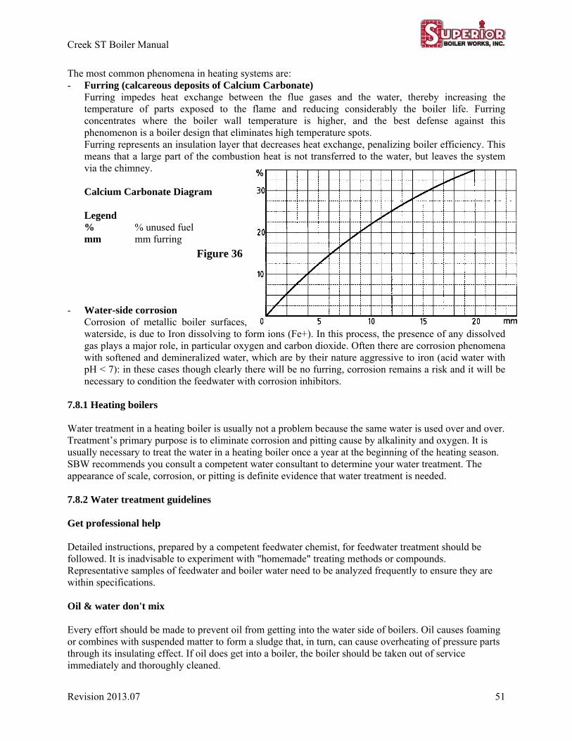
Creek ST Boiler Manual
Revision 2013.07 51
The most common phenomena in heating systems are: - Furring (calcareous deposits of Calcium Carbonate)
Furring impedes heat exchange between the flue gases and the water, thereby increasing the temperature of parts exposed to the flame and reducing considerably the boiler life. Furring concentrates where the boiler wall temperature is higher, and the best defense against this phenomenon is a boiler design that eliminates high temperature spots. Furring represents an insulation layer that decreases heat exchange, penalizing boiler efficiency. This means that a large part of the combustion heat is not transferred to the water, but leaves the system via the chimney. Calcium Carbonate Diagram Legend % % unused fuel mm mm furring
- Water-side corrosion Corrosion of metallic boiler surfaces, waterside, is due to Iron dissolving to form ions (Fe+). In this process, the presence of any dissolved gas plays a major role, in particular oxygen and carbon dioxide. Often there are corrosion phenomena with softened and demineralized water, which are by their nature aggressive to iron (acid water with pH < 7): in these cases though clearly there will be no furring, corrosion remains a risk and it will be necessary to condition the feedwater with corrosion inhibitors.
7.8.1 Heating boilers Water treatment in a heating boiler is usually not a problem because the same water is used over and over. Treatment’s primary purpose is to eliminate corrosion and pitting cause by alkalinity and oxygen. It is usually necessary to treat the water in a heating boiler once a year at the beginning of the heating season. SBW recommends you consult a competent water consultant to determine your water treatment. The appearance of scale, corrosion, or pitting is definite evidence that water treatment is needed. 7.8.2 Water treatment guidelines Get professional help Detailed instructions, prepared by a competent feedwater chemist, for feedwater treatment should be followed. It is inadvisable to experiment with "homemade" treating methods or compounds. Representative samples of feedwater and boiler water need to be analyzed frequently to ensure they are within specifications. Oil & water don't mix Every effort should be made to prevent oil from getting into the water side of boilers. Oil causes foaming or combines with suspended matter to form a sludge that, in turn, can cause overheating of pressure parts through its insulating effect. If oil does get into a boiler, the boiler should be taken out of service immediately and thoroughly cleaned.
Figure 36
Creek ST Boiler Manual
52 Revision 2013.07
Heating boilers should not breathe Use every practical means for excluding oxygen from boiler water. One source of oxygen is makeup water; therefore, hold makeup to a minimum. If a water boiler in a closed loop system loses more than 3 in. of water per month, this indicates there probably is a leak in some part of the system. The leak should be found and corrected. 7.9 Access openings and burner mount 7.9.1 Burner mount IMPORTANT: Check that the spaces between the burner sleeve and the boiler door are filled with thermal insulation (Figure 2). A piece of ceramic fiber insulation rope is provided with the boiler. If this is not suited to the specific burner fitted, use a rope of another diameter, of the same type of material. All details on the draft tube length, the diameter of the burner hole, and the pressurization are included in the part Technical Specifications. 7.9.2 Door Aperture For the models CRST-300 and CRST-500 models, the door can be opened in either direction (RH or LH). For the larger models if the door is to be opened to the opposite side, take the following steps. 1. Switch the outside nut (or bush) of one hinge with the diametrically opposite closure bush; then at the
hinge side, fasten the cone to the door with the inside nut. 2. Repeat the operation for the other hinge. 3. For any adjustment needed, act on the specific hinge nuts. For the door height adjustments see Fig. 34.

Creek ST Boiler Manual
Revision 2013.07 53
8 MAINTENANCE With proper operation and maintenance you can expect years of trouble-free service from your new boiler. The next few pages give guidelines for typical boiler maintenance. Cover plates, enclosures, and guards shall be maintained in place except during maintenance. Periodically, the waterside surfaces of the boiler should be visually checked for scale formation, pitting, and corrosion. Scale collection should not be thicker than an eggshell as scale is a good insulator and can considerably lower your boiler’s overall efficiency. When lowering the water level or draining the boiler for inspection, caution must be used. DO NOT DRAIN A HOT BOILER QUICKLY. Good practice dictates draining the boiler only after it has been out of service at least twenty-four (24) hours. IN NO CASE EVER FILL A WARM BOILER WITH COLD WATER. THIS WILL CAUSE LEAKAGE. If you want to reduce the time it takes to cool off the boiler, the burners fan can run cool air through the boiler. This is not a recommended practice, however in some cases the downtime cannot be afforded to allow the boiler to cool down slowly. 8.1 Spare Parts. Spare parts for controls, including electronic components which require time for procurement, should be maintained in stock supply. Spare parts should be kept in the boiler room or close by in a cool, dry place. In case you need to open up your boiler unexpectedly, it is a good idea to keep spare gaskets on hand. Many locations require that boilers are inspected once a year. Typically the yearly maintenance is conducted at the same time as this inspection. A full set of gaskets will be needed to reseal all access openings. Documenting the start-up is required to activate your warrantee. Keeping records of all boiler activities can be helpful in troubleshooting if you have a problem with operations. 8.2 Maintenance schedule The suggested maintenance schedule has been broken down into daily, weekly, monthly, semi-annual, and annual procedures. While the exact frequency of your inspections may vary, the schedule presented here is a good place to start. Over time you can determine exactly how often each item needs to be checked. Examples of maintenance logs are provided at the end of the manual. However the end user is responsible to create log sheets that match with the specifics of your system. A permanent log book should be provided in each boiler room to record maintenance work, inspection, certain tests, and other pertinent data. Brief details of repairs or other work done on a boiler plant (including time started, time completed, and signature of person in charge) should be recorded. Performance and results of test, inspections, or other routines required by codes or laws, insurance company inspection reports, and initial acceptance test data should be recorded. A double asterisk (**) is used to indicate that your boiler manual should also be checked for information on the topic being covered.
Creek ST Boiler Manual
54 Revision 2013.07
8.2.1 Daily procedure, also reference the burner manual’s procedures. 1. All water level controls should be tested for proper operation. 2. All gauges, monitors, and indicators should be checked for proper operation. 3. Observe burner starting sequence and flame characteristics to verify normal behavior. Check furnace
for debris and sooting, also inspect refractory through flame. 4. If an operating log is kept, enter reading; otherwise, conduct visual check of all pressure and
temperature gauge readings. 5. Check safety relief valves and inspection plugs for signs of leakage. 6. Check stack temperature. If temperature is higher than normal, check burner operation for over-firing
or improper combustion. 7. Check water sample readings for proper chemical treatment. 8. Check the condensate trap 8.2.2 Weekly procedure, also reference the burner manual’s procedures. 1. Check the temperature limit shutdown. During this check, observe the operation of the primary safety
to make sure that the operation is as described in the sequence of operation section of the burner manual.
2. Wipe the entire unit, particularly the operating parts, so that oil and dust do not accumulate. 3. Check combustion control operation as outlined in check list section of burner manual. Investigate and
correct any failure at once. ** 4. Check flame safety control’s response to lack of flame with main gas off. **
Interrupted Pilot – Start burner with pilot gas on, verify lockout. Determine that alarms are reacting to lockout.
5. Details about your lockout system timing should be provided with the burner manual. ** 6. During and after flame failure test, observe ignition spark and pilot flame for abnormalities. ** 7. Record pilot and main flame signals if proper meter is available. ** 8. Verify that main fuel valves are closing within specified timings; check valve position indicators. ** 9. If boiler is equipped with modulating burner, verify that adequate differential exists between operating
and modulating controls to prevent short cycling. ** 10. If you have chemicals being introduced directly into the boiler, check chemical feed equipment
against the check list supplied by your water treatment professional.
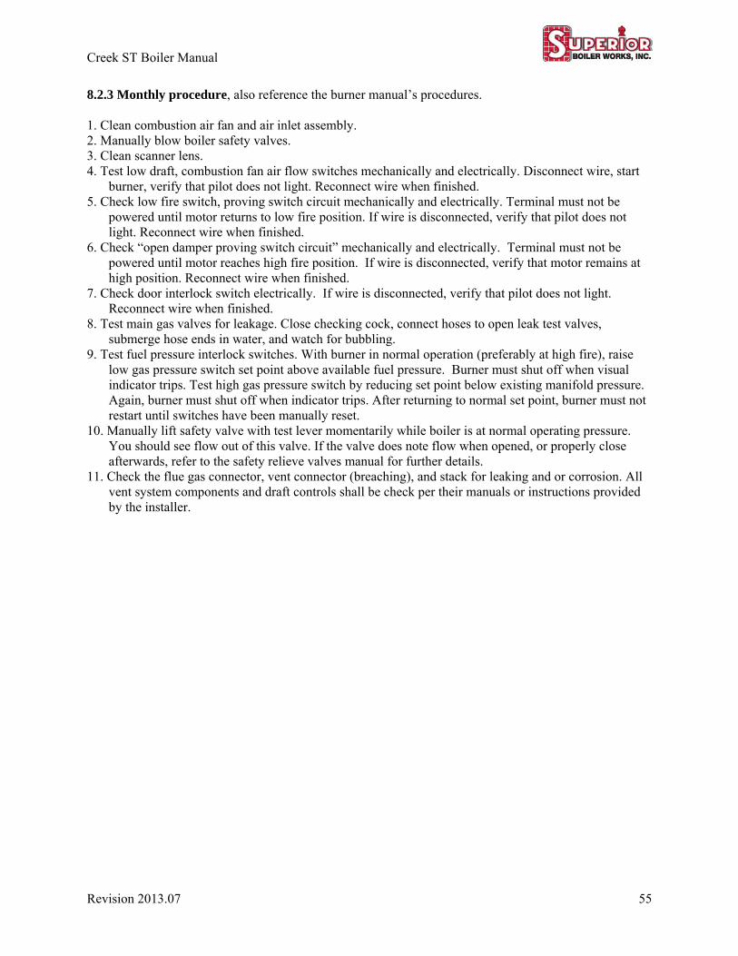
Creek ST Boiler Manual
Revision 2013.07 55
8.2.3 Monthly procedure, also reference the burner manual’s procedures.
1. Clean combustion air fan and air inlet assembly. 2. Manually blow boiler safety valves. 3. Clean scanner lens. 4. Test low draft, combustion fan air flow switches mechanically and electrically. Disconnect wire, start
burner, verify that pilot does not light. Reconnect wire when finished. 5. Check low fire switch, proving switch circuit mechanically and electrically. Terminal must not be
powered until motor returns to low fire position. If wire is disconnected, verify that pilot does not light. Reconnect wire when finished.
6. Check “open damper proving switch circuit” mechanically and electrically. Terminal must not be powered until motor reaches high fire position. If wire is disconnected, verify that motor remains at high position. Reconnect wire when finished.
7. Check door interlock switch electrically. If wire is disconnected, verify that pilot does not light. Reconnect wire when finished.
8. Test main gas valves for leakage. Close checking cock, connect hoses to open leak test valves, submerge hose ends in water, and watch for bubbling.
9. Test fuel pressure interlock switches. With burner in normal operation (preferably at high fire), raise low gas pressure switch set point above available fuel pressure. Burner must shut off when visual indicator trips. Test high gas pressure switch by reducing set point below existing manifold pressure. Again, burner must shut off when indicator trips. After returning to normal set point, burner must not restart until switches have been manually reset.
10. Manually lift safety valve with test lever momentarily while boiler is at normal operating pressure. You should see flow out of this valve. If the valve does note flow when opened, or properly close afterwards, refer to the safety relieve valves manual for further details.
11. Check the flue gas connector, vent connector (breaching), and stack for leaking and or corrosion. All vent system components and draft controls shall be check per their manuals or instructions provided by the installer.
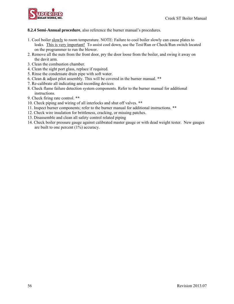
Creek ST Boiler Manual
56 Revision 2013.07
8.2.4 Semi-Annual procedure, also reference the burner manual’s procedures.
1. Cool boiler slowly to room temperature. NOTE: Failure to cool boiler slowly can cause plates to leaks. This is very important! To assist cool down, use the Test/Run or Check/Run switch located on the programmer to run the blower.
2. Remove all the nuts from the front door, pry the door loose from the boiler, and swing it away on the davit arm.
3. Clean the combustion chamber. 4. Clean the sight port glass, replace if required. 5. Rinse the condensate drain pipe with soft water. 6. Clean & adjust pilot assembly. This will be covered in the burner manual. ** 7. Re-calibrate all indicating and recording devices 8. Check flame failure detection system components. Refer to the burner manual for additional
instructions. 9. Check firing rate control. ** 10. Check piping and wiring of all interlocks and shut off valves. ** 11. Inspect burner components; refer to the burner manual for additional instructions. ** 12. Check wire insulation for brittleness, cracking, or missing patches. 13. Disassemble and clean all safety control related piping 14. Check boiler pressure gauge against calibrated master gauge or with dead weight tester. New gauges
are built to one percent (1%) accuracy.
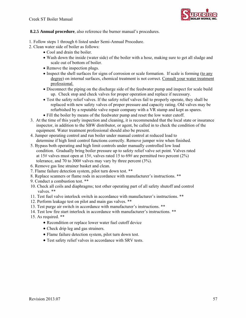
Creek ST Boiler Manual
Revision 2013.07 57
8.2.5 Annual procedure, also reference the burner manual’s procedures. 1. Follow steps 1 through 6 listed under Semi-Annual Procedure. 2. Clean water side of boiler as follows:
Cool and drain the boiler. Wash down the inside (water side) of the boiler with a hose, making sure to get all sludge and
scale out of bottom of boiler. Remove the inspection plugs. Inspect the shell surfaces for signs of corrosion or scale formation. If scale is forming (to any
degree) on internal surfaces, chemical treatment is not correct. Consult your water treatment professional.
Disconnect the piping on the discharge side of the feedwater pump and inspect for scale build up. Check stop and check valves for proper operation and replace if necessary.
Test the safety relief valves. If the safety relief valves fail to properly operate, they shall be replaced with new safety valves of proper pressure and capacity rating. Old valves may be refurbished by a reputable valve repair company with a VR stamp and kept as spares.
Fill the boiler by means of the feedwater pump and reset the low water cutoff. 3. At the time of this yearly inspection and cleaning, it is recommended that the local state or insurance
inspector, in addition to the SBW distributor, or agent, be called in to check the condition of the equipment. Water treatment professional should also be present.
4. Jumper operating control and run boiler under manual control at reduced load to determine if high limit control functions correctly. Remove jumper wire when finished.
5. Bypass both operating and high limit controls under manually controlled low load condition. Gradually bring boiler pressure up to safety relief valve set point. Valves rated at 15# valves must open at 15#, valves rated 15 to 69# are permitted two percent (2%) tolerance, and 70 to 300# valves may vary by three percent (3%).
6. Remove gas line strainer basket and clean. 7. Flame failure detection system, pilot turn down test. ** 8. Replace scanners or flame rods in accordance with manufacturer’s instructions. ** 9. Conduct a combustion test. ** 10. Check all coils and diaphragms; test other operating part of all safety shutoff and control
valves. ** 11. Test fuel valve interlock switch in accordance with manufacturer’s instructions. ** 12. Perform leakage test on pilot and main gas valves. ** 13. Test purge air switch in accordance with manufacturer’s instructions. ** 14. Test low fire start interlock in accordance with manufacturer’s instructions. ** 15. As required. **
Recondition or replace lower water fuel cutoff device Check drip leg and gas strainers. Flame failure detection system, pilot turn down test. Test safety relief valves in accordance with SRV tests.
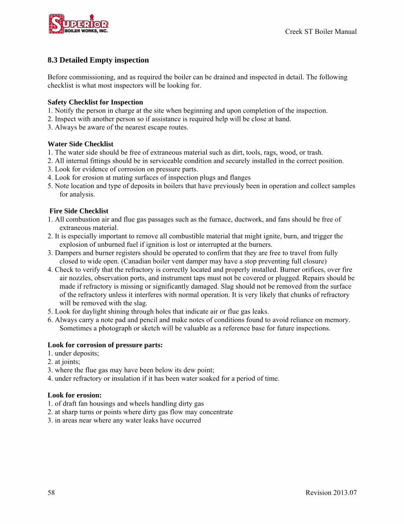
Creek ST Boiler Manual
58 Revision 2013.07
8.3 Detailed Empty inspection Before commissioning, and as required the boiler can be drained and inspected in detail. The following checklist is what most inspectors will be looking for. Safety Checklist for Inspection 1. Notify the person in charge at the site when beginning and upon completion of the inspection. 2. Inspect with another person so if assistance is required help will be close at hand. 3. Always be aware of the nearest escape routes. Water Side Checklist 1. The water side should be free of extraneous material such as dirt, tools, rags, wood, or trash. 2. All internal fittings should be in serviceable condition and securely installed in the correct position. 3. Look for evidence of corrosion on pressure parts. 4. Look for erosion at mating surfaces of inspection plugs and flanges 5. Note location and type of deposits in boilers that have previously been in operation and collect samples
for analysis. Fire Side Checklist 1. All combustion air and flue gas passages such as the furnace, ductwork, and fans should be free of
extraneous material. 2. It is especially important to remove all combustible material that might ignite, burn, and trigger the
explosion of unburned fuel if ignition is lost or interrupted at the burners. 3. Dampers and burner registers should be operated to confirm that they are free to travel from fully
closed to wide open. (Canadian boiler vent damper may have a stop preventing full closure) 4. Check to verify that the refractory is correctly located and properly installed. Burner orifices, over fire
air nozzles, observation ports, and instrument taps must not be covered or plugged. Repairs should be made if refractory is missing or significantly damaged. Slag should not be removed from the surface of the refractory unless it interferes with normal operation. It is very likely that chunks of refractory will be removed with the slag.
5. Look for daylight shining through holes that indicate air or flue gas leaks. 6. Always carry a note pad and pencil and make notes of conditions found to avoid reliance on memory.
Sometimes a photograph or sketch will be valuable as a reference base for future inspections. Look for corrosion of pressure parts: 1. under deposits; 2. at joints; 3. where the flue gas may have been below its dew point; 4. under refractory or insulation if it has been water soaked for a period of time. Look for erosion: 1. of draft fan housings and wheels handling dirty gas 2. at sharp turns or points where dirty gas flow may concentrate 3. in areas near where any water leaks have occurred
Creek ST Boiler Manual
Revision 2013.07 59
External Checklist: 1. Free access should be provided to the burner front, observation ports, and operating valves. 2. All instrumentation and controls should be complete, operational, and checked for proper calibration
and action. 3. External indicators permanently marked or installed on damper shafts and registers are necessary for
positive determination of position while the boiler is in service. 4. Personnel protection from hot surfaces should be provided by restricting access or by covering the hot
surfaces with insulation. 5. Find potential air or flue gas leaks in the furnace of out of service boilers operated with positive furnace
pressure by operating the forced draft fan at high flow rates. Leaks that can be felt or heard should be repaired before returning the boiler to service.
6. Safety relief valve outlets should be piped so they cannot discharge on people or any property that may be damaged. The discharge piping should be supported so that loads (piping weights and dynamic forces during operation) transmitted to the relief valves are minimized. The weight supported by the valve should not exceed the weight of a short elbow and drip pan or comparable weight of a direct connected free hanging discharge pipe. Installations requiring long discharge piping runs should not have those discharge piping runs directly connected to the valve. The valve manufacturer should be consulted if the weight to be loaded on a valve outlet exceeds a short elbow with a drip pan.
8.4 Limit control tests All limit controls should be tested periodically. Refer to the maintenance schedule as a starting point and discuss the details with your installer. A test gauge should be used to check the operation of all pressure controls. In general, the tests are to be performed as follows. Some tests may not apply to your specific installation. 8.4.1 High & Low gas pressure switch limit test & adjustment The maximum and minimum pressure range of the gas train is on the rating plates on the front of the boiler. If any readings are above this range, or if adjustments can’t be consistently made within this range, then other issues like pressure regulators or line pressure need to be addressed first. For setting and testing the gas pressure switches: Close the main manual gas shutoff valve and install a manometer or calibrated gauge in a test port that will see the same pressure as the switch. Reopen the main manual gas shutoff valve. When finished, close the main manual shutoff valve, remove calibrated gage or manometer, and restore the test plug. Restore the main manual gas valve to full open. Setting and testing the low gas pressure switch: Cycle the burner to high fire and a gas pressure reading. Using the main manual gas shutoff valve, throttle down the gas flow to a point there the reading is approximately 10% below the full open reading. Then adjust the low gas pressure switch until it breaks and shuts down the burner. Restore main manual gas shutoff valve to full open. Set the burner to high fire and use the main manual gas shutoff valve to throttle the gas flow. The low gas pressure switch should immediately break and shut down the burner at about 10% reduced pressure.

Creek ST Boiler Manual
60 Revision 2013.07
For setting and testing of the high gas pressure switch: If the high gas pressure switch (HGPS) is located downstream of the metering valve, adjustment and testing of the HGPS is performed at high fire. If the HGPS is located upstream of the metering valve, then adjustment and testing is performed at low fire. Cycle the burner to firing rate, and take gas pressure reading. Slowly adjust the switch until it breaks and shuts down the burner, then reverse the adjustment so that setting is approximately 10% greater than the reading at which the switch broke. 8.4.2 Electrical Limit Controls. All electrical current limiting or overload devices, including fuses and thermal overload elements, should be inspected to determine that they are properly sized and in good condition. Switches, starters, and relays should be checked for proper operation.

Creek ST Boiler Manual
Revision 2013.07 61
9 TROUBLESHOOTING If burner does not start, check the controller fault code in the burner manual. 1. Check all electric fuses. 2. Check water level in boiler. 3. Check limit controls to make sure they are making circuit. 4. Check the door interlock switch to make sure it is making circuit. 5. Push motor or starter reset button. 6. Push reset button on the programming control. 7. Push reset on high and low gas pressure switches. 8. Push reset button(s) on LWCO and temperature devices. 9. If burner then fails to start, call a qualified service technician. Refer to your burner manual, look for sections about start up, flame sensors, flame safe guard, etc... To stop burner 1. Switch off burner control switch or push emergency door switch. 2. Do not kill the feedwater pump until boiler is cooled or boiler is full. Burner adjustments The burner manual should be used for reference on burner adjustment. 1. The flame should not be impinging on the walls of the furnace. 2. If you are having problems adjusting the flame using the burner controls, draft controls may need to be
adjusted, or added if not present. Switch problems 1. Probe style switches (common LWCO) can give a false closed switch signal because of contamination.
Clean water side of probe holder. Leaking If water starts coming out of the smoke box door, this is common during initial cold start up. If this does happen during start up, but stops after the boiler has warmed up, this is ok. If this happens during normal operation when the boiler is warm, then you may have a leak. This could also just be the result of condensation if the boiler room is humid. If you believe you have a leak, call your local boiler service technician. Fan rotation Even when factory tested, the fan motor can be wired backwards in the field. Observe the fan rotation indicator marked on the fan. The diagram below shows how the three phase wiring can control a fan going clockwise (cw) vs. counterclockwise (ccw). In general, incorrect fan rotation is corrected by switching the position of two wires.
Fan rotation wiring
Figure 37
Creek ST Boiler Manual
62 Revision 2013.07
10 Out of service operations 10.1 Shutdown
When shutting down a boiler, switch the burner to manual, set the burner to low fire for a few moments, and then turn the burner off. As the boiler flow drops toward zero, it will probably be necessary to close the main feedwater isolation valve and manually regulate drum water level with the bypass valve. Most flow control valves will not shut off tightly. When the drum level stabilizes with no water flowing, the boiler may be isolated. When the non-return valve, if any, on the water outlet has closed, close inlet valves and outlet valve. Run down the stem on the non-return valve to hold the disk on its seat. Where two stop valves are used, open the drain between them and see that it is clear and bleeds off the pressure in the line. After pressure falls, slowly open the drum vents to prevent formation of a vacuum that might cause subsequent leakage at gasketed joints. 10.2 Boiler taken out of service
When a boiler is taken out of service, it should be laid-up using either the wet or dry procedure.
SBW does not warranty boilers out of operation that are not properly laid up for extended periods of time. If the boiler could be subject to freezing temperatures when out of service, the boiler must be laid up dry.
If draining the boiler is not practical, the laid up wet procedure may be used. Wet boiler layups are not recommended for periods longer than 30 days. SBW does not Warranty boilers laid up wet for more than 30 days. ALWAYS KEEP THE FUEL SUPPLY VALVE(S) SHUT OFF IF THE BURNER IS SHUT DOWN FOR AN EXTENDED PERIOD OF TIME. 10.3 Boiler laid up dry 1. Allow the boiler to cool and shut of the water supply. 2. Drain, clean, and dry the boiler thoroughly (both fire and water sides) 3. Fuel and electricity to the unit shall be shut off. Use proper tag and lock out procedures. 4. An oil coating of fire side metal surfaces is beneficial when the boiler is not used for extended periods
of time. This will prevent oxidization of the metal. Care should be taken to avoid putting oil on the firebox thermal blankets.
5. Place desiccant inside the boiler, primary junction box, and burner control panel 6. Close up all opening to the boiler preventing leakage of humid air into the boiler. 7. When the lay-up time is finished, see the re-commissioning section
NOTICE!
Creek ST Boiler Manual
Revision 2013.07 63
10.4 Boiler laid up wet procedure 1. Fill the boiler to overflowing with the highest quality water available. Steam condensate, soft water, or
filtered fresh water all generally acceptable. Raw city water should not be used. 2. While maintaining boiler water temperature at 120°F minimum to remove oxygen, drain off boiler
water from boiler drain until it runs clear. 3. Add enough caustic soda to the hot water to maintain approximately three hundred fifty (350) parts per
million of alkalinity and also add enough sodium sulfite to produce a residue of sixty (60) parts per million of this chemical.
4. When all the dissolved gases are released and chemicals mixed into the water (approximately 1 hr) 5. Completely close up the water side of the boiler so that open air does not come into contact with the
water. 6. Dry the flue gas side of the boiler. 7. Fuel and electricity to the unit shall be shut off. Use proper tag and lock out procedures. 8. The fire side should then be cleaned. An oil coating of fire side metal surfaces is beneficial when the
boiler is not used for extended periods of time. This will prevent oxidization of the metal. Care should be taken to avoid putting oil on the firebox thermal blankets.
9. Place desiccant on wooden or plastic trays in the fireside of the boiler. Do not fill the trays more than half way. Also place small amount of desiccant in the junction box and burner control panel.
10. Close up all opening to the boiler preventing leakage of humid air into the boiler. 11. When the lay-up time if finished, see the re-commissioning section. 12. When the boiler is done with a laid-up wet period of time, make sure blowdown is conducted during
start up. 10.5 Re-commissioning 1. When approaching the end of your lay-up time, review the operator logs for any items that may need to
be replaced. Some items can take time to procure. 2. Check that you have gaskets/seals to replace any that have been opened. This likely includes gaskets
for: Smoke box doors, inspection plugs, and sight glass. Your spare parts list will be helpful in determining exactly what is needed. SBW or SBW representative can supply you with spare parts.
3. Remove all desiccants placed within the boiler except boiler lizards placed in the water side of the boiler can be left inside.
4. If the boiler was laid up dry, rinse out the water side of the boiler 5. Remove your tag and lock outs 6. See the start-up section of this manual. Boil-out procedures do not need to be repeated unless
inspection finds oil buildup inside the water side.
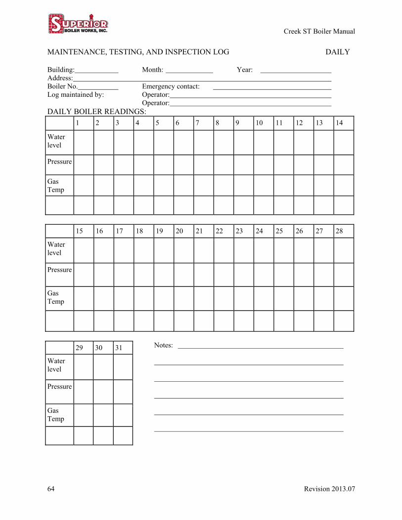
Creek ST Boiler Manual
64 Revision 2013.07
MAINTENANCE, TESTING, AND INSPECTION LOG DAILY
Building: Month: Year: Address: Boiler No. Emergency contact: Log maintained by: Operator: Operator: DAILY BOILER READINGS:
1 2 3 4 5 6 7 8 9 10 11 12 13 14
Water level
Pressure
Gas Temp
15 16 17 18 19 20 21 22 23 24 25 26 27 28
Water level
Pressure
Gas Temp
29 30 31
Water level
Pressure
Gas Temp
Notes:
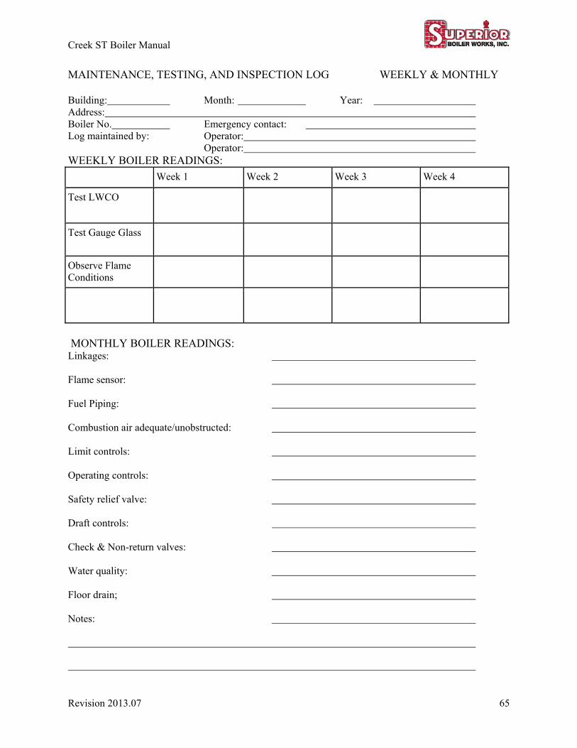
Creek ST Boiler Manual
Revision 2013.07 65
MAINTENANCE, TESTING, AND INSPECTION LOG WEEKLY & MONTHLY Building: Month: Year: Address: Boiler No. Emergency contact: Log maintained by: Operator: Operator: WEEKLY BOILER READINGS:
Week 1 Week 2 Week 3 Week 4
Test LWCO
Test Gauge Glass
Observe Flame Conditions
MONTHLY BOILER READINGS: Linkages: Flame sensor: Fuel Piping: Combustion air adequate/unobstructed: Limit controls: Operating controls: Safety relief valve: Draft controls: Check & Non-return valves: Water quality: Floor drain; Notes:
Creek ST Boiler Manual
66 Revision 2013.07
CREEK ST BOILER MANUAL Condensing Water Boiler
300 - 2000 MBtu/Hr. Gas