creating and maintaining vlans -...
TRANSCRIPT
C H A P T E R
5-1 Cisco IOS Desktop Switching Software Configuration Guide
78-6511-04
5Creating and Maintaining VLANs
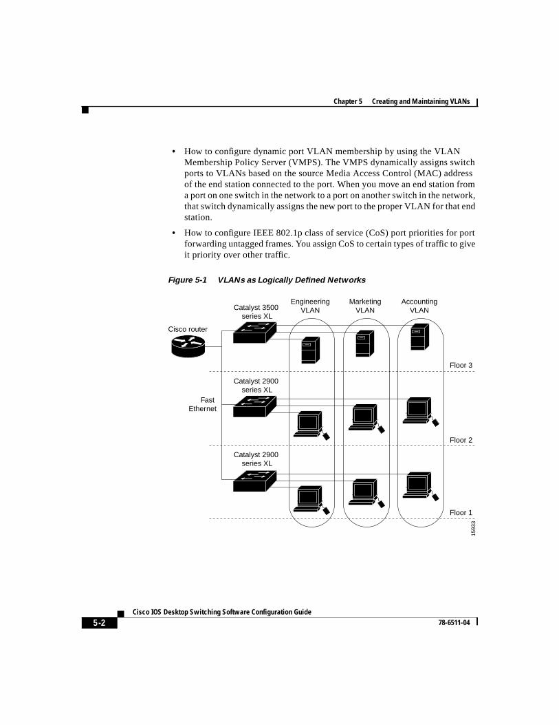
A virtual LAN (VLAN) is a switched network that is logically segmented byfunction, project team, or application, without regard to the physical locations ofthe users. Any switch port can belong to a VLAN, and unicast, broadcast, andmulticast packets are forwarded and flooded only to stations in the VLAN. EachVLAN is considered a logical network, and packets destined for stations that donot belong to the VLAN must be forwarded through a router or bridge as shownin Figure 5-1. Because a VLAN is considered a separate logical network, itcontains its own bridge Management Information Base (MIB) information andcan support its own implementation of the Spanning Tree Protocol (STP).
This chapter describes how to create and maintain VLANs through the ClusterManagement software and the command-line interface (CLI). It contains thefollowing information:
• How to configure static-access and multi-VLAN ports without having theVLAN Trunk Protocol (VTP) database globally propagate VLANconfiguration information.
• How VTP works and how to configure its domain name, modes, version, andpruning capability.
• How to add, modify, and remove VLANs with different media characteristicsto and from the VTP database.
• How to configure Fast Ethernet and Gigabit Ethernet VLAN trunks on aswitch. The switch supports Inter-Switch Link (ISL) and IEEE 802.1Qtrunking methods of transmitting VLAN traffic. This section describes howto configure the allowed-VLAN list, the pruning-eligible list, and the nativeVLAN for untagged traffic. Two methods of load sharing using STP are alsodescribed.
Chapter 5 Creating and Maintaining VLANs
5-2Cisco IOS Desktop Switching Software Configuration Guide
78-6511-04
• How to configure dynamic port VLAN membership by using the VLANMembership Policy Server (VMPS). The VMPS dynamically assigns switchports to VLANs based on the source Media Access Control (MAC) addressof the end station connected to the port. When you move an end station froma port on one switch in the network to a port on another switch in the network,that switch dynamically assigns the new port to the proper VLAN for that endstation.
• How to configure IEEE 802.1p class of service (CoS) port priorities for portforwarding untagged frames. You assign CoS to certain types of traffic to giveit priority over other traffic.
Figure 5-1 VLANs as Logically Defined Networks
Floor 1
Floor 2
EngineeringVLAN
Cisco router
Fast Ethernet
Catalyst 2900 series XL
Catalyst 3500 series XL
Floor 3
MarketingVLAN
AccountingVLAN
1593
3
Catalyst 2900 series XL
5-3 Cisco IOS Desktop Switching Software Configuration Guide
78-6511-04
Chapter 5 Creating and Maintaining VLANsNumber of Supported VLANs
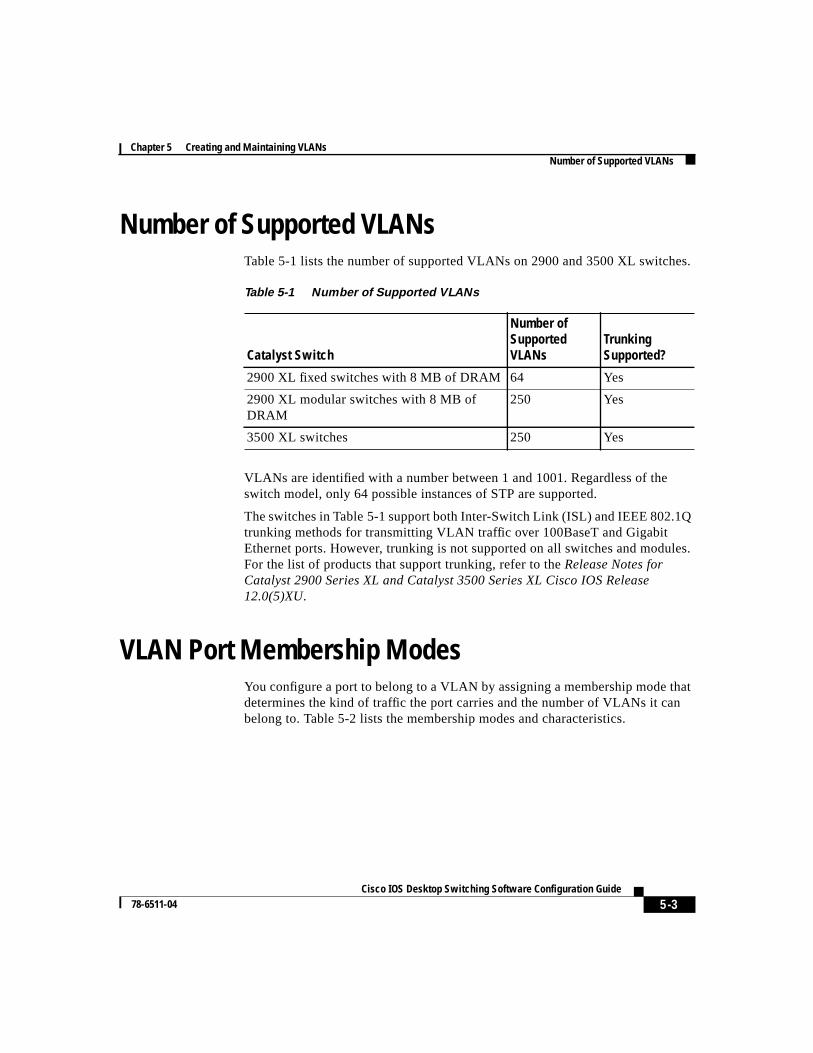
Number of Supported VLANsTable 5-1 lists the number of supported VLANs on 2900 and 3500 XL switches.
VLANs are identified with a number between 1 and 1001. Regardless of theswitch model, only 64 possible instances of STP are supported.
The switches in Table 5-1 support both Inter-Switch Link (ISL) and IEEE 802.1Qtrunking methods for transmitting VLAN traffic over 100BaseT and GigabitEthernet ports. However, trunking is not supported on all switches and modules.For the list of products that support trunking, refer to theRelease Notes forCatalyst 2900 Series XL and Catalyst 3500 Series XL Cisco IOS Release12.0(5)XU.
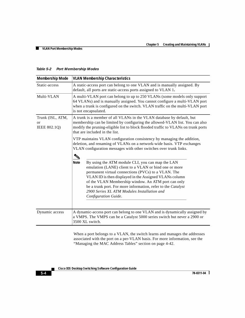
VLAN Port Membership ModesYou configure a port to belong to a VLAN by assigning a membership mode thatdetermines the kind of traffic the port carries and the number of VLANs it canbelong to. Table 5-2 lists the membership modes and characteristics.
Table 5-1 Number of Supported VLANs
Catalyst Switch
Number ofSupportedVLANs
TrunkingSupported?
2900 XL fixed switches with 8 MB of DRAM 64 Yes
2900 XL modular switches with 8 MB ofDRAM
250 Yes
3500 XL switches 250 Yes
Chapter 5 Creating and Maintaining VLANsVLAN Port Membership Modes
5-4Cisco IOS Desktop Switching Software Configuration Guide
78-6511-04
When a port belongs to a VLAN, the switch learns and manages the addressesassociated with the port on a per-VLAN basis. For more information, see the“Managing the MAC Address Tables” section on page 4-42.
Table 5-2 Port Membership Modes
Membership Mode VLAN Membership Characteristics
Static-access A static-access port can belong to one VLAN and is manually assigned. Bydefault, all ports are static-access ports assigned to VLAN 1.
Multi-VLAN A multi-VLAN port can belong to up to 250 VLANs (some models only support64 VLANs) and is manually assigned. You cannot configure a multi-VLAN portwhen a trunk is configured on the switch. VLAN traffic on the multi-VLAN portis not encapsulated.
Trunk (ISL, ATM,orIEEE 802.1Q)
A trunk is a member of all VLANs in the VLAN database by default, butmembership can be limited by configuring the allowed-VLAN list. You can alsomodify the pruning-eligible list to block flooded traffic to VLANs on trunk portsthat are included in the list.
VTP maintains VLAN configuration consistency by managing the addition,deletion, and renaming of VLANs on a network-wide basis. VTP exchangesVLAN configuration messages with other switches over trunk links.
Note By using the ATM module CLI, you can map the LANemulation (LANE) client to a VLAN or bind one or morepermanent virtual connections (PVCs) to a VLAN. TheVLAN ID is then displayed in the Assigned VLANs columnof the VLAN Membership window. An ATM port can onlybe a trunk port. For more information, refer to theCatalyst2900 Series XL ATM Modules Installation andConfiguration Guide.
Dynamic access A dynamic-access port can belong to one VLAN and is dynamically assigned bya VMPS. The VMPS can be a Catalyst 5000 series switch but never a 2900 or3500 XL switch.
5-5 Cisco IOS Desktop Switching Software Configuration Guide
78-6511-04
Chapter 5 Creating and Maintaining VLANsVLAN Port Membership Modes
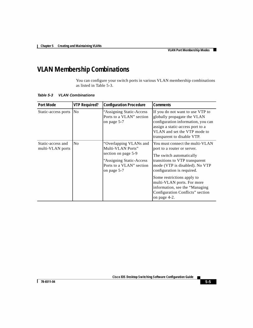
VLAN Membership CombinationsYou can configure your switch ports in various VLAN membership combinationsas listed in Table 5-3.
Table 5-3 VLAN Combinations
Port Mode VTP Required? Configuration Procedure Comments
Static-access ports No “Assigning Static-AccessPorts to a VLAN” sectionon page 5-7
If you do not want to use VTP toglobally propagate the VLANconfiguration information, you canassign a static-access port to aVLAN and set the VTP mode totransparent to disable VTP.
Static-access andmulti-VLAN ports
No “Overlapping VLANs andMulti-VLAN Ports”section on page 5-9
“Assigning Static-AccessPorts to a VLAN” sectionon page 5-7
You must connect the multi-VLANport to a router or server.
The switch automaticallytransitions to VTP transparentmode (VTP is disabled). No VTPconfiguration is required.
Some restrictions apply tomulti-VLAN ports. For moreinformation, see the “ManagingConfiguration Conflicts” sectionon page 4-2.
Chapter 5 Creating and Maintaining VLANsVLAN Port Membership Modes
5-6Cisco IOS Desktop Switching Software Configuration Guide
78-6511-04
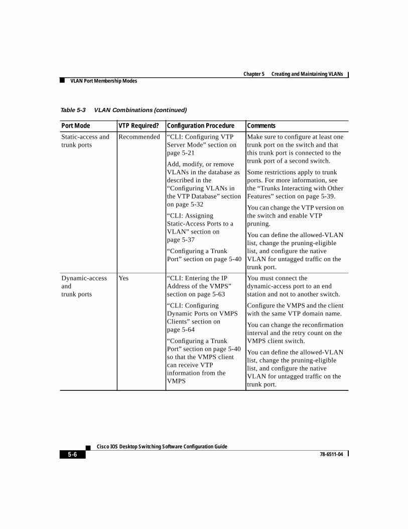
Static-access andtrunk ports
Recommended “CLI: Configuring VTPServer Mode” section onpage 5-21
Add, modify, or removeVLANs in the database asdescribed in the“Configuring VLANs inthe VTP Database” sectionon page 5-32
“CLI: AssigningStatic-Access Ports to aVLAN” section onpage 5-37
“Configuring a TrunkPort” section on page 5-40
Make sure to configure at least onetrunk port on the switch and thatthis trunk port is connected to thetrunk port of a second switch.
Some restrictions apply to trunkports. For more information, seethe “Trunks Interacting with OtherFeatures” section on page 5-39.
You can change the VTP version onthe switch and enable VTPpruning.
You can define the allowed-VLANlist, change the pruning-eligiblelist, and configure the nativeVLAN for untagged traffic on thetrunk port.
Dynamic-accessandtrunk ports
Yes “CLI: Entering the IPAddress of the VMPS”section on page 5-63
“CLI: ConfiguringDynamic Ports on VMPSClients” section onpage 5-64
“Configuring a TrunkPort” section on page 5-40so that the VMPS clientcan receive VTPinformation from theVMPS
You must connect thedynamic-access port to an endstation and not to another switch.
Configure the VMPS and the clientwith the same VTP domain name.
You can change the reconfirmationinterval and the retry count on theVMPS client switch.
You can define the allowed-VLANlist, change the pruning-eligiblelist, and configure the nativeVLAN for untagged traffic on thetrunk port.
Table 5-3 VLAN Combinations (continued)
Port Mode VTP Required? Configuration Procedure Comments
5-7 Cisco IOS Desktop Switching Software Configuration Guide
78-6511-04
Chapter 5 Creating and Maintaining VLANsAssigning Static-Access Ports to a VLAN
Clusters, VLAN Membership, and the Management VLANThis software release supports the grouping of switches into a cluster that can bemanaged as a single entity. The command switch is the single point ofmanagement for the cluster and cluster members.
Links among a command switch, cluster members, and candidate switches mustbe through ports that belong to the management VLAN. By default, themanagement VLAN is VLAN 1. If you are using SNMP or the ClusterManagement Suite (CMS) to manage the switch, ensure that the port throughwhich you are connected to a switch is in the management VLAN. Forinformation on configuring the management VLAN, see the “Changing theManagement VLAN” section on page 3-33.
If you are configuring VLANs on a member switch, you might need to enter anextra command from the command-switch CLI to access the member switch.When configuring port parameters, for example, you can use the privileged EXECrcommand command and the number of the member switch to display themember-switch CLI. Once you have accessed the member switch, command modechanges, and IOS commands operate as usual. Enterexit on the member switchin privileged EXEC mode to return to the command-switch CLI.
For more information about thercommand command, refer to theCisco IOSDesktop Switching Command Reference (online only).
Assigning Static-Access Ports to a VLANBy default, all ports are static-access ports assigned to the management VLAN,VLAN 1.
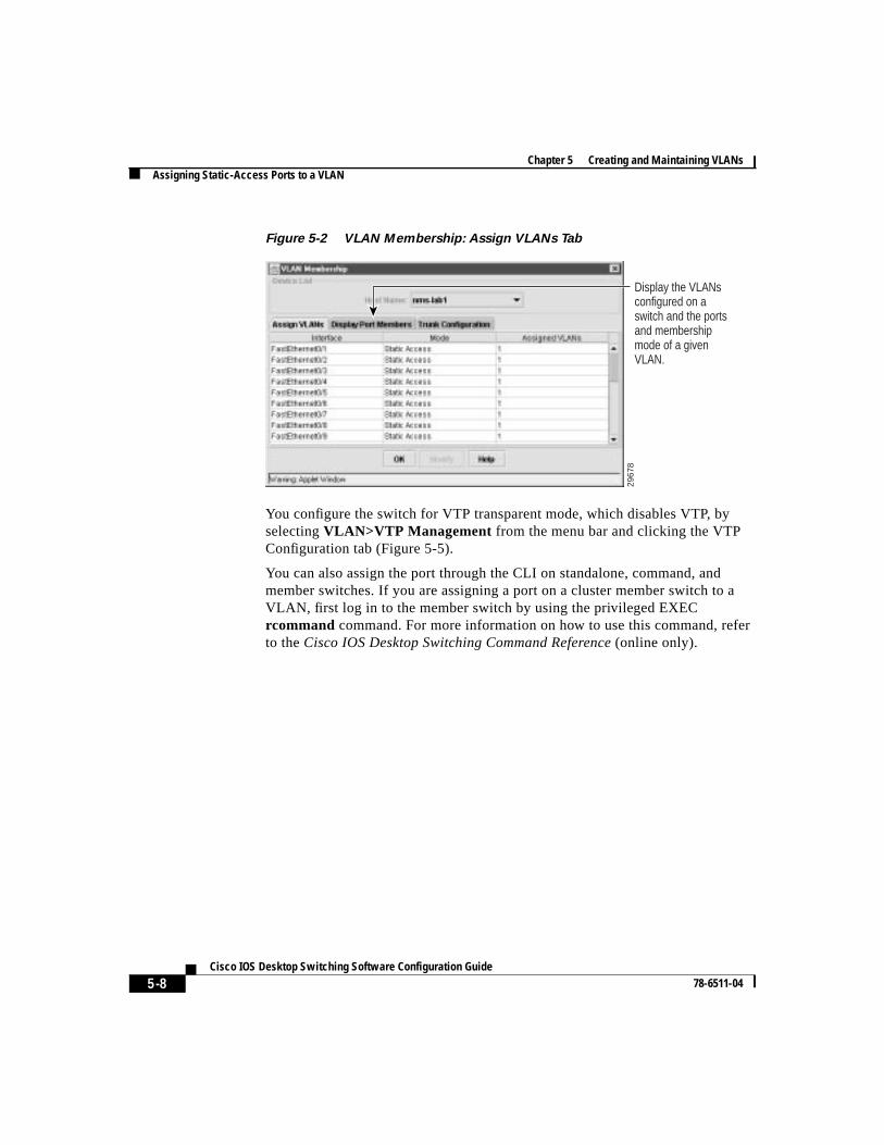
You can assign a static-access port to a VLAN without having VTP globallypropagate VLAN configuration information (VTP is disabled). To assign aVLAN, you access the VLAN Membership window (Figure 5-2) by selectingVLAN>VLAN Membership from the menu bar and clicking the Assign VLANstab.
Chapter 5 Creating and Maintaining VLANsAssigning Static-Access Ports to a VLAN
5-8Cisco IOS Desktop Switching Software Configuration Guide
78-6511-04
Figure 5-2 VLAN Membership: Assign VLANs Tab
You configure the switch for VTP transparent mode, which disables VTP, byselectingVLAN>VTP Management from the menu bar and clicking the VTPConfiguration tab (Figure 5-5).
You can also assign the port through the CLI on standalone, command, andmember switches. If you are assigning a port on a cluster member switch to aVLAN, first log in to the member switch by using the privileged EXECrcommand command. For more information on how to use this command, referto theCisco IOS Desktop Switching Command Reference (online only).
2967
8
Display the VLANs configured on a switch and the ports and membership mode of a given VLAN.
5-9 Cisco IOS Desktop Switching Software Configuration Guide
78-6511-04
Chapter 5 Creating and Maintaining VLANsOverlapping VLANs and Multi-VLAN Ports
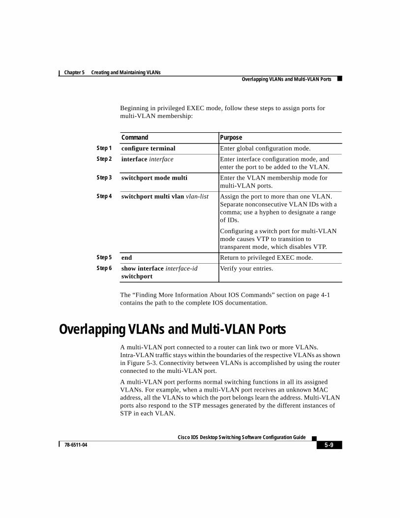
Beginning in privileged EXEC mode, follow these steps to assign ports formulti-VLAN membership:
The “Finding More Information About IOS Commands” section on page 4-1contains the path to the complete IOS documentation.
Overlapping VLANs and Multi-VLAN PortsA multi-VLAN port connected to a router can link two or more VLANs.Intra-VLAN traffic stays within the boundaries of the respective VLANs as shownin Figure 5-3. Connectivity between VLANs is accomplished by using the routerconnected to the multi-VLAN port.
A multi-VLAN port performs normal switching functions in all its assignedVLANs. For example, when a multi-VLAN port receives an unknown MACaddress, all the VLANs to which the port belongs learn the address. Multi-VLANports also respond to the STP messages generated by the different instances ofSTP in each VLAN.
Command Purpose
Step 1 configure terminal Enter global configuration mode.
Step 2 interface interface Enter interface configuration mode, andenter the port to be added to the VLAN.
Step 3 switchport mode multi Enter the VLAN membership mode formulti-VLAN ports.
Step 4 switchport multi vlan vlan-list Assign the port to more than one VLAN.Separate nonconsecutive VLAN IDs with acomma; use a hyphen to designate a rangeof IDs.
Configuring a switch port for multi-VLANmode causes VTP to transition totransparent mode, which disables VTP.
Step 5 end Return to privileged EXEC mode.
Step 6 show interfaceinterface-idswitchport
Verify your entries.
Chapter 5 Creating and Maintaining VLANsOverlapping VLANs and Multi-VLAN Ports
5-10Cisco IOS Desktop Switching Software Configuration Guide
78-6511-04
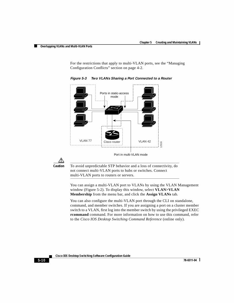
For the restrictions that apply to multi-VLAN ports, see the “ManagingConfiguration Conflicts” section on page 4-2.
Figure 5-3 Two VLANs Sharing a Port Connected to a Router
Caution To avoid unpredictable STP behavior and a loss of connectivity, donot connect multi-VLAN ports to hubs or switches. Connectmulti-VLAN ports to routers or servers.
You can assign a multi-VLAN port to VLANs by using the VLAN Managementwindow (Figure 5-2). To display this window, selectVLAN>VLANMembership from the menu bar, and click theAssign VLANs tab.
You can also configure the multi-VLAN port through the CLI on standalone,command, and member switches. If you are assigning a port on a cluster memberswitch to a VLAN, first log into the member switch by using the privileged EXECrcommand command. For more information on how to use this command, referto theCisco IOS Desktop Switching Command Reference (online only).
VLAN 42
1251
6Cisco routerVLAN 77
Ports in static-accessmode
Port in multi-VLAN mode
5-11 Cisco IOS Desktop Switching Software Configuration Guide
78-6511-04
Chapter 5 Creating and Maintaining VLANsUsing the VLAN Trunk Protocol
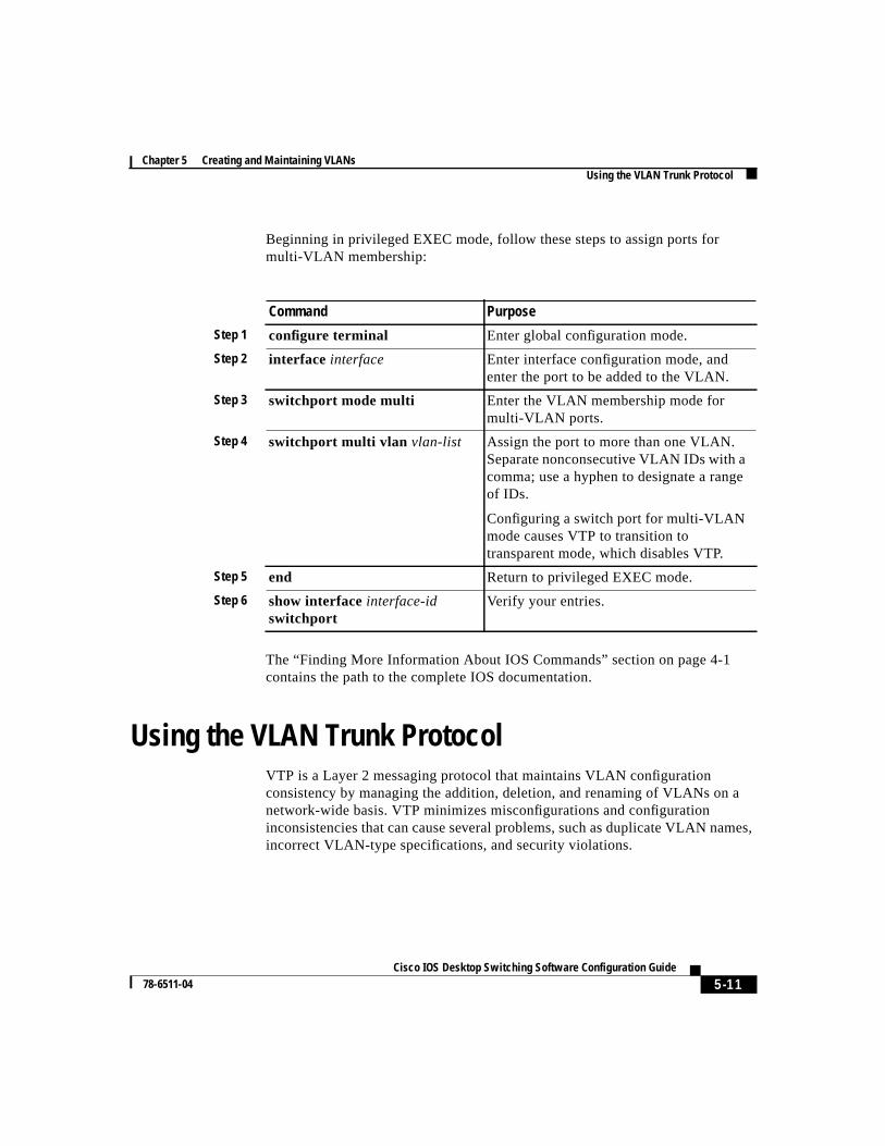
Beginning in privileged EXEC mode, follow these steps to assign ports formulti-VLAN membership:
The “Finding More Information About IOS Commands” section on page 4-1contains the path to the complete IOS documentation.
Using the VLAN Trunk ProtocolVTP is a Layer 2 messaging protocol that maintains VLAN configurationconsistency by managing the addition, deletion, and renaming of VLANs on anetwork-wide basis. VTP minimizes misconfigurations and configurationinconsistencies that can cause several problems, such as duplicate VLAN names,incorrect VLAN-type specifications, and security violations.
Command Purpose
Step 1 configure terminal Enter global configuration mode.
Step 2 interface interface Enter interface configuration mode, andenter the port to be added to the VLAN.
Step 3 switchport mode multi Enter the VLAN membership mode formulti-VLAN ports.
Step 4 switchport multi vlan vlan-list Assign the port to more than one VLAN.Separate nonconsecutive VLAN IDs with acomma; use a hyphen to designate a rangeof IDs.
Configuring a switch port for multi-VLANmode causes VTP to transition totransparent mode, which disables VTP.
Step 5 end Return to privileged EXEC mode.
Step 6 show interfaceinterface-idswitchport
Verify your entries.
Chapter 5 Creating and Maintaining VLANsUsing the VLAN Trunk Protocol
5-12Cisco IOS Desktop Switching Software Configuration Guide
78-6511-04
Before you create VLANs, you must decide whether to use VTP in your network.Using VTP, you can make configuration changes centrally on a single switch, suchas a 2900 or 3500 XL switch, and have those changes automaticallycommunicated to all the other switches in the network. Without VTP, you cannotsend information about VLANs to other switches.
The VTP DomainA VTP domain (also called a VLAN management domain) consists of one switchor several interconnected switches under the same administrative responsibility.A switch can be in only one VTP domain. You make global VLAN configurationchanges for the domain by using the CLI, Cluster Management software, orSimple Network Management Protocol (SNMP).
By default, a 2900 or 3500 XL switch is in the no-management-domain state untilit receives an advertisement for a domain over a trunk link (a link that carries thetraffic of multiple VLANs) or until you configure a domain name. The defaultVTP mode is server mode, but VLAN information is not propagated over thenetwork until a domain name is specified or learned.
If the switch receives a VTP advertisement over a trunk link, it inherits the domainname and configuration revision number. The switch then ignores advertisementswith a different domain name or an earlier configuration revision number.
When you make a change to the VLAN configuration on a VTP server, the changeis propagated to all switches in the VTP domain. VTP advertisements are sentover all trunk connections, including Inter-Switch Link (ISL), IEEE 802.1Q,IEEE 802.10, and Asynchronous Transfer Mode (ATM) LAN Emulation (LANE).
If you configure a switch for VTP transparent mode, you can create and modifyVLANs, but the changes are not transmitted to other switches in the domain, andthey affect only the individual switch.
For domain name and password configuration guidelines, see the “DomainNames” section on page 5-16.
5-13 Cisco IOS Desktop Switching Software Configuration Guide
78-6511-04
Chapter 5 Creating and Maintaining VLANsUsing the VLAN Trunk Protocol
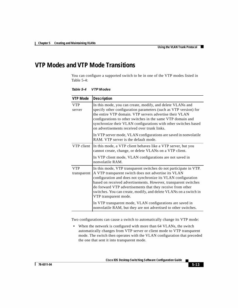
VTP Modes and VTP Mode TransitionsYou can configure a supported switch to be in one of the VTP modes listed inTable 5-4:
Two configurations can cause a switch to automatically change its VTP mode:
• When the network is configured with more than 64 VLANs, the switchautomatically changes from VTP server or client mode to VTP transparentmode. The switch then operates with the VLAN configuration that precededthe one that sent it into transparent mode.
Table 5-4 VTP Modes
VTP Mode Description
VTPserver
In this mode, you can create, modify, and delete VLANs andspecify other configuration parameters (such as VTP version) forthe entire VTP domain. VTP servers advertise their VLANconfigurations to other switches in the same VTP domain andsynchronize their VLAN configurations with other switches basedon advertisements received over trunk links.
In VTP server mode, VLAN configurations are saved in nonvolatileRAM. VTP server is the default mode.
VTP client In this mode, a VTP client behaves like a VTP server, but youcannot create, change, or delete VLANs on a VTP client.
In VTP client mode, VLAN configurations are not saved innonvolatile RAM.
VTPtransparent
In this mode, VTP transparent switches do not participate in VTP.A VTP transparent switch does not advertise its VLANconfiguration and does not synchronize its VLAN configurationbased on received advertisements. However, transparent switchesdo forward VTP advertisements that they receive from otherswitches. You can create, modify, and delete VLANs on a switch inVTP transparent mode.
In VTP transparent mode, VLAN configurations are saved innonvolatile RAM, but they are not advertised to other switches.
Chapter 5 Creating and Maintaining VLANsUsing the VLAN Trunk Protocol
5-14Cisco IOS Desktop Switching Software Configuration Guide
78-6511-04
• When a multi-VLAN port is configured on a supported switch in VTP servermode or client mode, the switch automatically changes to transparent mode.
The “VTP Configuration Guidelines” section on page 5-16 provides tips andcaveats for configuring VTP.
VTP AdvertisementsEach switch in the VTP domain sends periodic global configurationadvertisements from each trunk port to a reserved multicast address. Neighboringswitches receive these advertisements and update their VTP and VLANconfigurations as necessary.
Note Because trunk ports send and receive VTP advertisements, you mustensure that at least one trunk port is configured on the switch andthat this trunk port is connected to the trunk port of a second switch.Otherwise, the switch cannot receive any VTP advertisements.
VTP advertisements distribute the following global domain information in VTPadvertisements:
• VTP domain name
• VTP configuration revision number
• Update identity and update timestamp
• MD5 digest
VTP advertisements distribute the following VLAN information for eachconfigured VLAN:
• VLAN ID
• VLAN name
• VLAN type
• VLAN state
• Additional VLAN configuration information specific to the VLAN type
5-15 Cisco IOS Desktop Switching Software Configuration Guide
78-6511-04
Chapter 5 Creating and Maintaining VLANsUsing the VLAN Trunk Protocol
VTP Version 2VTP version 2 supports the following features not supported in version 1:
• Token Ring support—VTP version 2 supports Token Ring LAN switchingand VLANs (Token Ring Bridge Relay Function [TrBRF] and Token RingConcentrator Relay Function [TrCRF]). For more information about TokenRing VLANs, see the “VLANs in the VTP Database” section on page 5-27.
• Unrecognized Type-Length-Value (TLV) support—A VTP server or clientpropagates configuration changes to its other trunks, even for TLVs it is notable to parse. The unrecognized TLV is saved in nonvolatile RAM when theswitch is operating in VTP server mode.
• Version-Dependent Transparent Mode—In VTP version 1, a VTP transparentswitch inspects VTP messages for the domain name and version and forwardsa message only if the version and domain name match. Because only onedomain is supported, VTP version 2 forwards VTP messages in transparentmode without checking the version and domain name.
• Consistency Checks—In VTP version 2, VLAN consistency checks (such asVLAN names and values) are performed only when you enter newinformation through the CLI, the Cluster Management software, or SNMP.Consistency checks are not performed when new information is obtainedfrom a VTP message or when information is read from nonvolatile RAM. Ifthe digest on a received VTP message is correct, its information is acceptedwithout consistency checks.
VTP PruningPruning increases available bandwidth by restricting flooded traffic to those trunklinks that the traffic must use to reach the destination devices. Without VTPpruning, a switch floods broadcast, multicast, and unknown unicast traffic acrossall trunk links within a VTP domain even though receiving switches might discardthem.
VTP pruning blocks unneeded flooded traffic to VLANs on trunk ports that areincluded in the pruning-eligible list. Only VLANs included in thepruning-eligible list can be pruned. By default, VLANs 2 through 1001 are
Chapter 5 Creating and Maintaining VLANsUsing the VLAN Trunk Protocol
5-16Cisco IOS Desktop Switching Software Configuration Guide
78-6511-04
pruning eligible on 2900 and 3500 XL trunk ports. If the VLANs are configuredas pruning-ineligible, the flooding continues. VTP pruning is also supported withVTP version 1 and version 2.
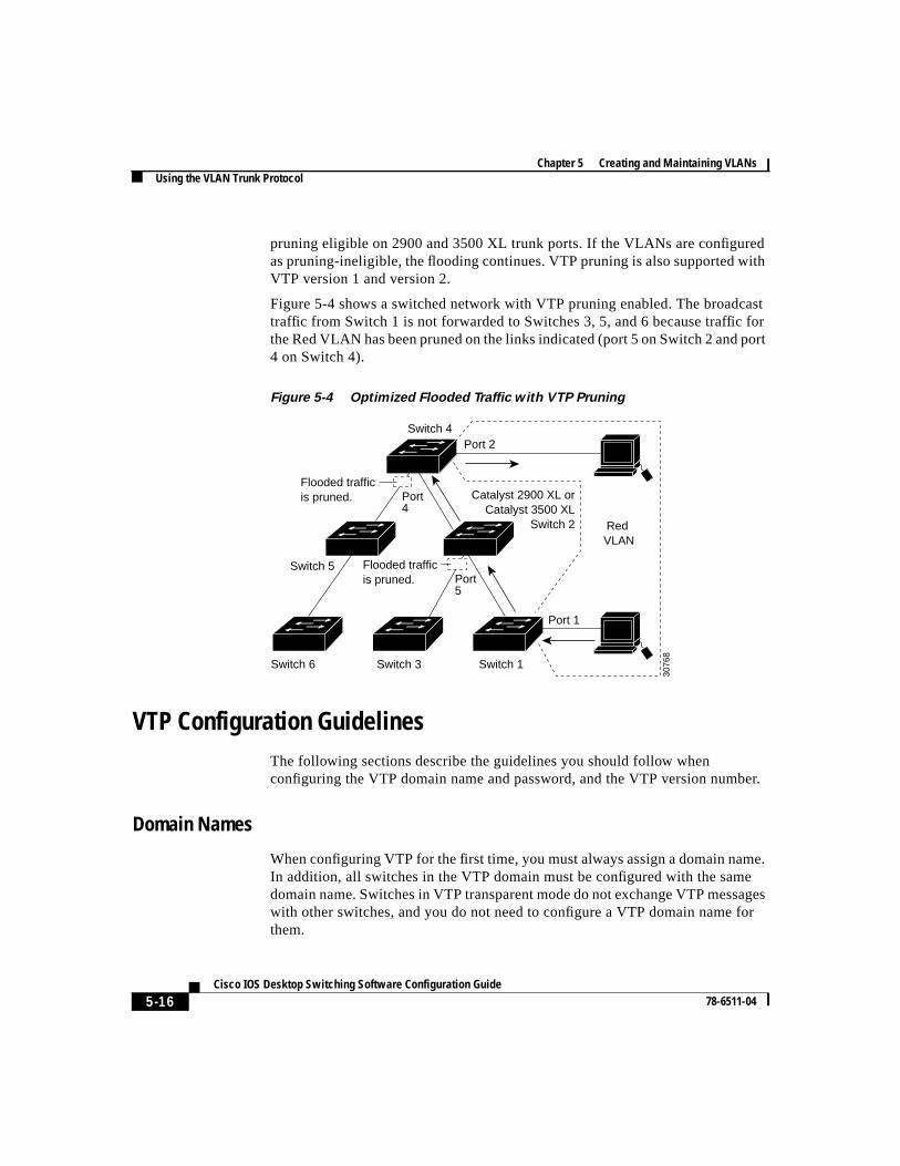
Figure 5-4 shows a switched network with VTP pruning enabled. The broadcasttraffic from Switch 1 is not forwarded to Switches 3, 5, and 6 because traffic forthe Red VLAN has been pruned on the links indicated (port 5 on Switch 2 and port4 on Switch 4).
Figure 5-4 Optimized Flooded Traffic with VTP Pruning
VTP Configuration GuidelinesThe following sections describe the guidelines you should follow whenconfiguring the VTP domain name and password, and the VTP version number.
Domain Names
When configuring VTP for the first time, you must always assign a domain name.In addition, all switches in the VTP domain must be configured with the samedomain name. Switches in VTP transparent mode do not exchange VTP messageswith other switches, and you do not need to configure a VTP domain name forthem.
Switch 4
Switch 5
Switch 3Switch 6 Switch 1
Catalyst 2900 XL orCatalyst 3500 XL
Switch 2
Port 1
Port 2
Red VLAN
3076
8
Port4
Port5
Flooded trafficis pruned.
Flooded trafficis pruned.
5-17 Cisco IOS Desktop Switching Software Configuration Guide
78-6511-04
Chapter 5 Creating and Maintaining VLANsUsing the VLAN Trunk Protocol
Caution Do not configure a VTP domain if all switches are operating in VTPclient mode. If you configure the domain, it is impossible to makechanges to the VLAN configuration of that domain. Therefore, makesure you configure at least one switch in the VTP domain for VTPserver mode.
Passwords
You can configure a password for the VTP domain, but it is not required. Alldomain switches must share the same password. Switches without a password orwith the wrong password reject VTP advertisements.
Caution The domain does not function properly if you do not assign the samepassword to each switch in the domain.
If you configure a VTP password for a domain, a 2900 or 3500 XL switch that isbooted without a VTP configuration does not accept VTP advertisements untilyou configure it with the correct password. After the configuration, the switchaccepts the next VTP advertisement that uses the same password and domainname in the advertisement.
If you are adding a new switch to an existing network that has VTP capability, thenew switch learns the domain name only after the applicable password has beenconfigured on the switch.
Upgrading from Previous Software Releases
When you upgrade from a software version that supports VLANs but does notsupport VTP, such as Cisco IOS Release 11.2(8)SA3, to a version that doessupport VTP, ports that belong to a VLAN retain their VLAN membership, andVTP enters transparent mode. The domain name becomes UPGRADE, and VTPdoes not propagate the VLAN configuration to other switches.
If you want the switch to propagate VLAN configuration information to otherswitches and to learn the VLANs enabled on the network, you must configure theswitch with the correct domain name, the domain password, and change the VTPmode to VTP server.
Chapter 5 Creating and Maintaining VLANsUsing the VLAN Trunk Protocol
5-18Cisco IOS Desktop Switching Software Configuration Guide
78-6511-04
VTP Version
Follow these guidelines when deciding which VTP version to implement:
• All switches in a VTP domain must run the same VTP version.
• A VTP version 2-capable switch can operate in the same VTP domain as aswitch running VTP version 1 if version 2 is disabled on the version2-capable switch (version 2 is disabled by default).
• Do not enable VTP version 2 on a switch unless all of the switches in thesame VTP domain are version-2-capable. When you enable version 2 on aswitch, all of the version-2-capable switches in the domain enable version 2.If there is a version 1-only switch, it will not exchange VTP information withswitches with version 2 enabled.
• If there are Token Ring networks in your environment (TrBRF and TrCRF),you must enable VTP version 2 for Token Ring VLAN switching to functionproperly. To run Token Ring and Token Ring-Net, disable VTP version 2.
• Enabling or disabling VTP pruning on a VTP server enables or disables VTPpruning for the entire VTP domain.
Default VTP ConfigurationTable 5-5 shows the default VTP configuration.
Table 5-5 VTP Default Configuration
Feature Default Value
VTP domain name Null.
VTP mode Server.
VTP version 2 enablestate
Version 2 is disabled.
VTP password None.
VTP pruning Disabled.
5-19 Cisco IOS Desktop Switching Software Configuration Guide
78-6511-04
Chapter 5 Creating and Maintaining VLANsUsing the VLAN Trunk Protocol
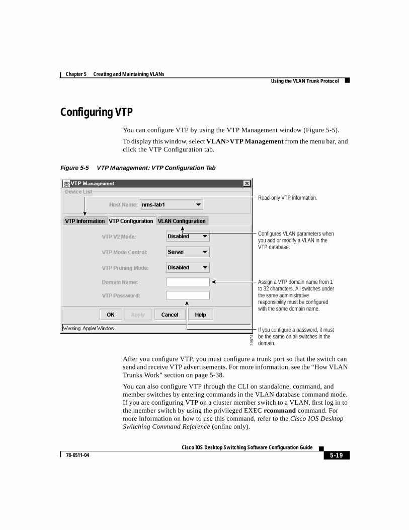
Configuring VTPYou can configure VTP by using the VTP Management window (Figure 5-5).
To display this window, selectVLAN>VTP Management from the menu bar, andclick the VTP Configuration tab.
Figure 5-5 VTP Management: VTP Configuration Tab
After you configure VTP, you must configure a trunk port so that the switch cansend and receive VTP advertisements. For more information, see the “How VLANTrunks Work” section on page 5-38.
You can also configure VTP through the CLI on standalone, command, andmember switches by entering commands in the VLAN database command mode.If you are configuring VTP on a cluster member switch to a VLAN, first log in tothe member switch by using the privileged EXECrcommand command. Formore information on how to use this command, refer to theCisco IOS DesktopSwitching Command Reference (online only).
2967
4
Assign a VTP domain name from 1 to 32 characters. All switches under the same administrative responsibility must be configured with the same domain name.
Read-only VTP information.
Configures VLAN parameters when you add or modify a VLAN in the VTP database.
If you configure a password, it must be the same on all switches in the domain.
Chapter 5 Creating and Maintaining VLANsUsing the VLAN Trunk Protocol
5-20Cisco IOS Desktop Switching Software Configuration Guide
78-6511-04
When you enter theexit command in VLAN database mode, it applies all thecommands that you entered. VTP messages are sent to other switches in the VTPdomain, and you are returned to privileged EXEC mode.
Note The Cisco IOS end and Ctrl-Z commands are not supported inVLAN database mode.
5-21 Cisco IOS Desktop Switching Software Configuration Guide
78-6511-04
Chapter 5 Creating and Maintaining VLANsUsing the VLAN Trunk Protocol
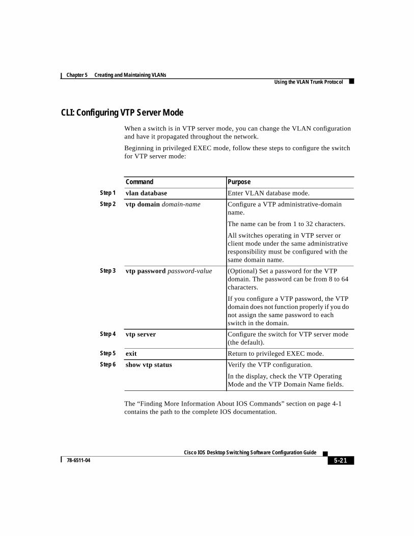
CLI: Configuring VTP Server Mode
When a switch is in VTP server mode, you can change the VLAN configurationand have it propagated throughout the network.
Beginning in privileged EXEC mode, follow these steps to configure the switchfor VTP server mode:
The “Finding More Information About IOS Commands” section on page 4-1contains the path to the complete IOS documentation.
Command Purpose
Step 1 vlan database Enter VLAN database mode.
Step 2 vtp domain domain-name Configure a VTP administrative-domainname.
The name can be from 1 to 32 characters.
All switches operating in VTP server orclient mode under the same administrativeresponsibility must be configured with thesame domain name.
Step 3 vtp passwordpassword-value (Optional) Set a password for the VTPdomain. The password can be from 8 to 64characters.
If you configure a VTP password, the VTPdomain does not function properly if you donot assign the same password to eachswitch in the domain.
Step 4 vtp server Configure the switch for VTP server mode(the default).
Step 5 exit Return to privileged EXEC mode.
Step 6 show vtp status Verify the VTP configuration.
In the display, check the VTP OperatingMode and the VTP Domain Name fields.
Chapter 5 Creating and Maintaining VLANsUsing the VLAN Trunk Protocol
5-22Cisco IOS Desktop Switching Software Configuration Guide
78-6511-04
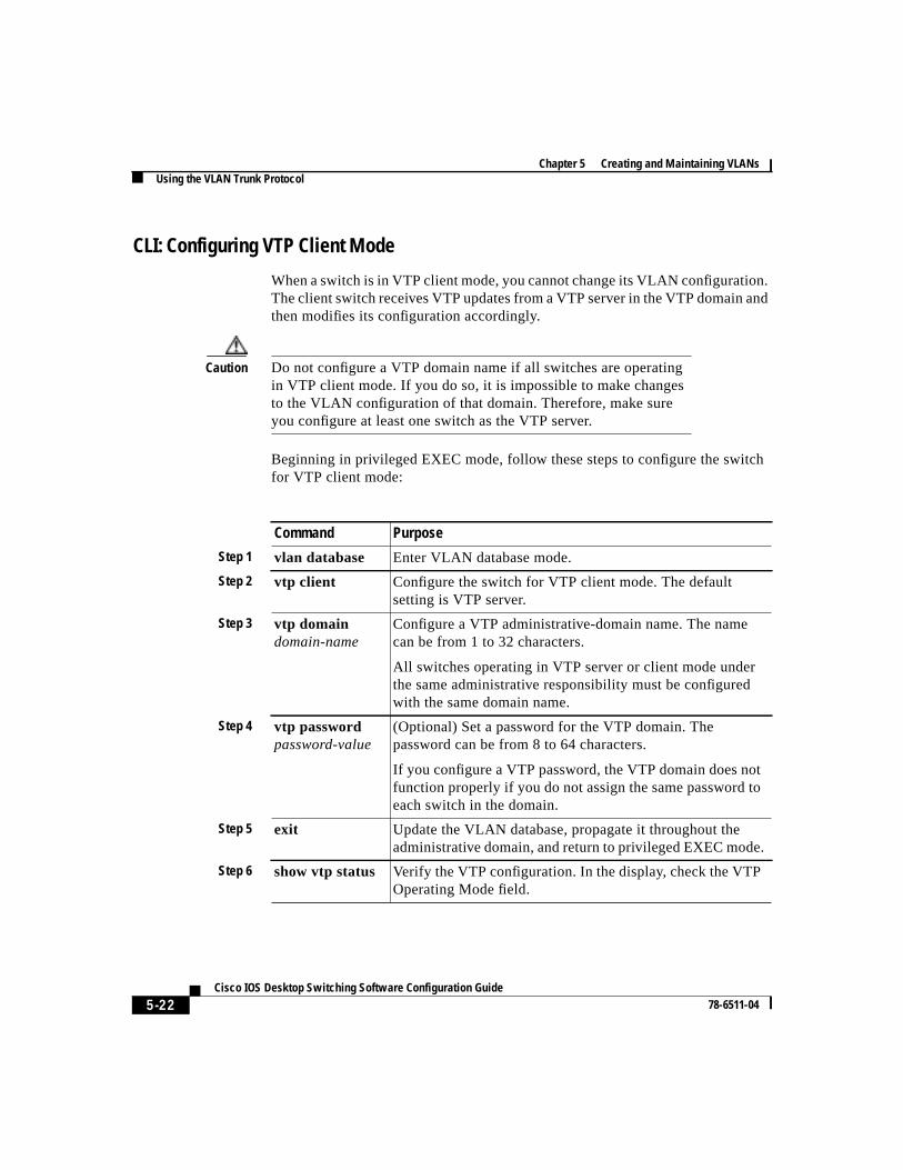
CLI: Configuring VTP Client Mode
When a switch is in VTP client mode, you cannot change its VLAN configuration.The client switch receives VTP updates from a VTP server in the VTP domain andthen modifies its configuration accordingly.
Caution Do not configure a VTP domain name if all switches are operatingin VTP client mode. If you do so, it is impossible to make changesto the VLAN configuration of that domain. Therefore, make sureyou configure at least one switch as the VTP server.
Beginning in privileged EXEC mode, follow these steps to configure the switchfor VTP client mode:
Command Purpose
Step 1 vlan database Enter VLAN database mode.
Step 2 vtp client Configure the switch for VTP client mode. The defaultsetting is VTP server.
Step 3 vtp domaindomain-name
Configure a VTP administrative-domain name. The namecan be from 1 to 32 characters.
All switches operating in VTP server or client mode underthe same administrative responsibility must be configuredwith the same domain name.
Step 4 vtp passwordpassword-value
(Optional) Set a password for the VTP domain. Thepassword can be from 8 to 64 characters.
If you configure a VTP password, the VTP domain does notfunction properly if you do not assign the same password toeach switch in the domain.
Step 5 exit Update the VLAN database, propagate it throughout theadministrative domain, and return to privileged EXEC mode.
Step 6 show vtp status Verify the VTP configuration. In the display, check the VTPOperating Mode field.
5-23 Cisco IOS Desktop Switching Software Configuration Guide
78-6511-04
Chapter 5 Creating and Maintaining VLANsUsing the VLAN Trunk Protocol
The “Finding More Information About IOS Commands” section on page 4-1contains the path to the complete IOS documentation.
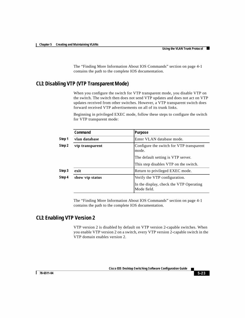
CLI: Disabling VTP (VTP Transparent Mode)
When you configure the switch for VTP transparent mode, you disable VTP onthe switch. The switch then does not send VTP updates and does not act on VTPupdates received from other switches. However, a VTP transparent switch doesforward received VTP advertisements on all of its trunk links.
Beginning in privileged EXEC mode, follow these steps to configure the switchfor VTP transparent mode:
The “Finding More Information About IOS Commands” section on page 4-1contains the path to the complete IOS documentation.
CLI: Enabling VTP Version 2
VTP version 2 is disabled by default on VTP version 2-capable switches. Whenyou enable VTP version 2 on a switch, every VTP version 2-capable switch in theVTP domain enables version 2.
Command Purpose
Step 1 vlan database Enter VLAN database mode.
Step 2 vtp transparent Configure the switch for VTP transparentmode.
The default setting is VTP server.
This step disables VTP on the switch.
Step 3 exit Return to privileged EXEC mode.
Step 4 show vtp status Verify the VTP configuration.
In the display, check the VTP OperatingMode field.
Chapter 5 Creating and Maintaining VLANsUsing the VLAN Trunk Protocol
5-24Cisco IOS Desktop Switching Software Configuration Guide
78-6511-04
Caution VTP version 1 and VTP version 2 are not interoperable on switchesin the same VTP domain. Every switch in the VTP domain must usethe same VTP version. Do not enable VTP version 2 unless everyswitch in the VTP domain supports version 2.
Note In a Token Ring environment, you must enable VTP version 2 forToken Ring VLAN switching to function properly.
For more information on VTP version configuration guidelines, see the “VTPVersion” section on page 5-18.
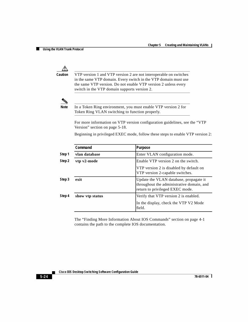
Beginning in privileged EXEC mode, follow these steps to enable VTP version 2:
The “Finding More Information About IOS Commands” section on page 4-1contains the path to the complete IOS documentation.
Command Purpose
Step 1 vlan database Enter VLAN configuration mode.
Step 2 vtp v2-mode Enable VTP version 2 on the switch.
VTP version 2 is disabled by default onVTP version 2-capable switches.
Step 3 exit Update the VLAN database, propagate itthroughout the administrative domain, andreturn to privileged EXEC mode.
Step 4 show vtp status Verify that VTP version 2 is enabled.
In the display, check the VTP V2 Modefield.
5-25 Cisco IOS Desktop Switching Software Configuration Guide
78-6511-04
Chapter 5 Creating and Maintaining VLANsUsing the VLAN Trunk Protocol
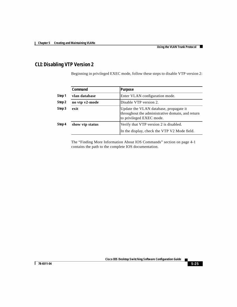
CLI: Disabling VTP Version 2
Beginning in privileged EXEC mode, follow these steps to disable VTP version 2:
The “Finding More Information About IOS Commands” section on page 4-1contains the path to the complete IOS documentation.
Command Purpose
Step 1 vlan database Enter VLAN configuration mode.
Step 2 no vtp v2-mode Disable VTP version 2.
Step 3 exit Update the VLAN database, propagate itthroughout the administrative domain, and returnto privileged EXEC mode.
Step 4 show vtp status Verify that VTP version 2 is disabled.
In the display, check the VTP V2 Mode field.
Chapter 5 Creating and Maintaining VLANsUsing the VLAN Trunk Protocol
5-26Cisco IOS Desktop Switching Software Configuration Guide
78-6511-04
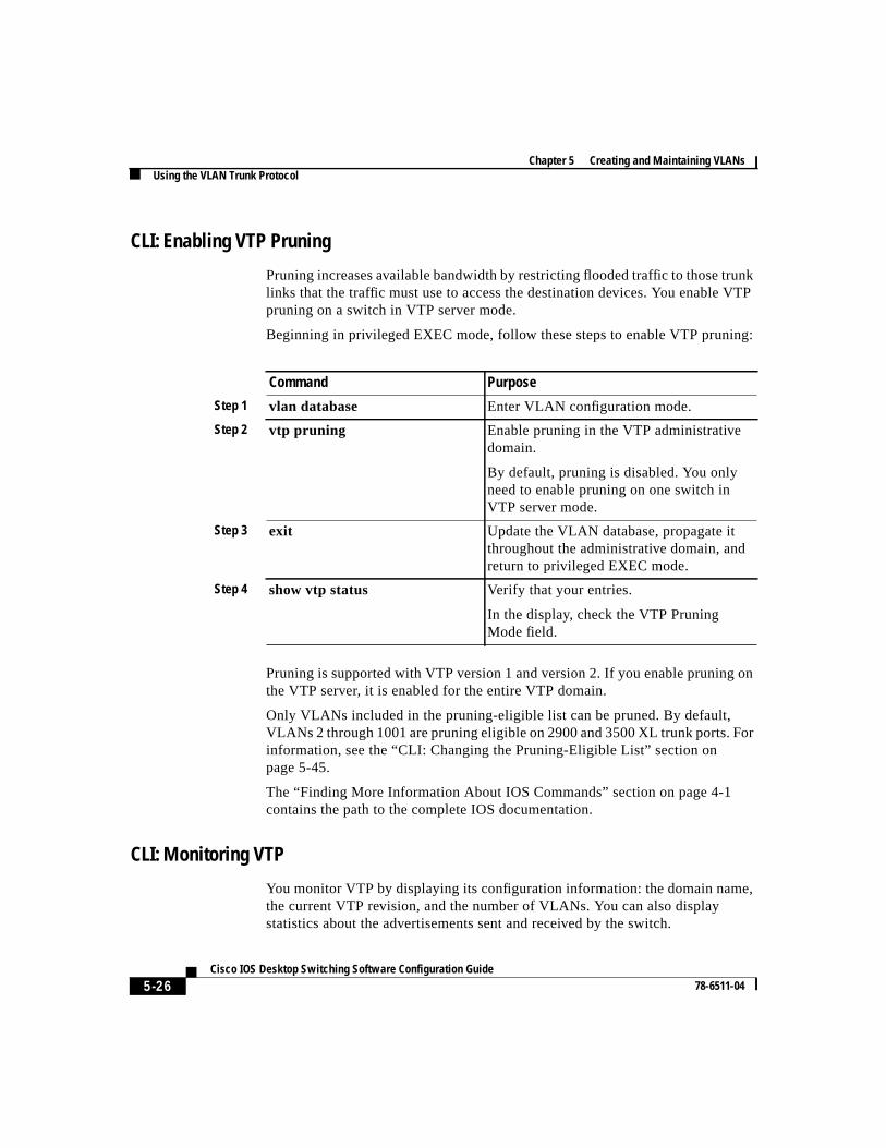
CLI: Enabling VTP Pruning
Pruning increases available bandwidth by restricting flooded traffic to those trunklinks that the traffic must use to access the destination devices. You enable VTPpruning on a switch in VTP server mode.
Beginning in privileged EXEC mode, follow these steps to enable VTP pruning:
Pruning is supported with VTP version 1 and version 2. If you enable pruning onthe VTP server, it is enabled for the entire VTP domain.
Only VLANs included in the pruning-eligible list can be pruned. By default,VLANs 2 through 1001 are pruning eligible on 2900 and 3500 XL trunk ports. Forinformation, see the “CLI: Changing the Pruning-Eligible List” section onpage 5-45.
The “Finding More Information About IOS Commands” section on page 4-1contains the path to the complete IOS documentation.
CLI: Monitoring VTP
You monitor VTP by displaying its configuration information: the domain name,the current VTP revision, and the number of VLANs. You can also displaystatistics about the advertisements sent and received by the switch.
Command Purpose
Step 1 vlan database Enter VLAN configuration mode.
Step 2 vtp pruning Enable pruning in the VTP administrativedomain.
By default, pruning is disabled. You onlyneed to enable pruning on one switch inVTP server mode.
Step 3 exit Update the VLAN database, propagate itthroughout the administrative domain, andreturn to privileged EXEC mode.
Step 4 show vtp status Verify that your entries.
In the display, check the VTP PruningMode field.
5-27 Cisco IOS Desktop Switching Software Configuration Guide
78-6511-04
Chapter 5 Creating and Maintaining VLANsVLANs in the VTP Database
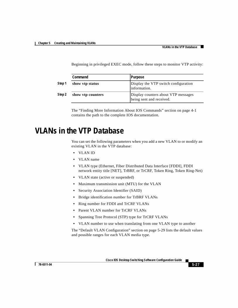
Beginning in privileged EXEC mode, follow these steps to monitor VTP activity:
The “Finding More Information About IOS Commands” section on page 4-1contains the path to the complete IOS documentation.
VLANs in the VTP DatabaseYou can set the following parameters when you add a new VLAN to or modify anexisting VLAN in the VTP database:
• VLAN ID
• VLAN name
• VLAN type (Ethernet, Fiber Distributed Data Interface [FDDI], FDDInetwork entity title [NET], TrBRF, or TrCRF, Token Ring, Token Ring-Net)
• VLAN state (active or suspended)
• Maximum transmission unit (MTU) for the VLAN
• Security Association Identifier (SAID)
• Bridge identification number for TrBRF VLANs
• Ring number for FDDI and TrCRF VLANs
• Parent VLAN number for TrCRF VLANs
• Spanning Tree Protocol (STP) type for TrCRF VLANs
• VLAN number to use when translating from one VLAN type to another
The “Default VLAN Configuration” section on page 5-29 lists the default valuesand possible ranges for each VLAN media type.
Command Purpose
Step 1 show vtp status Display the VTP switch configurationinformation.
Step 2 show vtp counters Display counters about VTP messagesbeing sent and received.
Chapter 5 Creating and Maintaining VLANsVLANs in the VTP Database
5-28Cisco IOS Desktop Switching Software Configuration Guide
78-6511-04
Token Ring VLANsAlthough the 2900 and 3500 XL switches do not support Token Ring connections,a remote device such as a Catalyst 5000 series switch with Token Ringconnections could be managed from one of the supported switches. Switchesrunning this IOS release advertise information about the following Token RingVLANs when running VTP version 2:
• Token Ring TrBRF VLANs
• Token Ring TrCRF VLANs
For more information on configuring Token Ring VLANs, see theCatalyst 5000Series Software Configuration Guide.
VLAN Configuration GuidelinesFollow these guidelines when creating and modifying VLANs in your network:
• A maximum of 250 VLANs can be active on supported switches, and somemodels only support 64 VLANs. If VTP reports that there are 254 activeVLANs, 4 of the active VLANs (1002 to 1005) are reserved for Token Ringand FDDI.
• Before you can create a VLAN, the switch must be in VTP server mode orVTP transparent mode. For information on configuring VTP, see the“Configuring VTP” section on page 5-19.
• Switches running this IOS release do not support Token Ring or FDDI media.The switch does not forward FDDI, FDDI-Net, TrCRF, or TrBRF traffic, butit does propagate the VLAN configuration through VTP.
5-29 Cisco IOS Desktop Switching Software Configuration Guide
78-6511-04
Chapter 5 Creating and Maintaining VLANsVLANs in the VTP Database
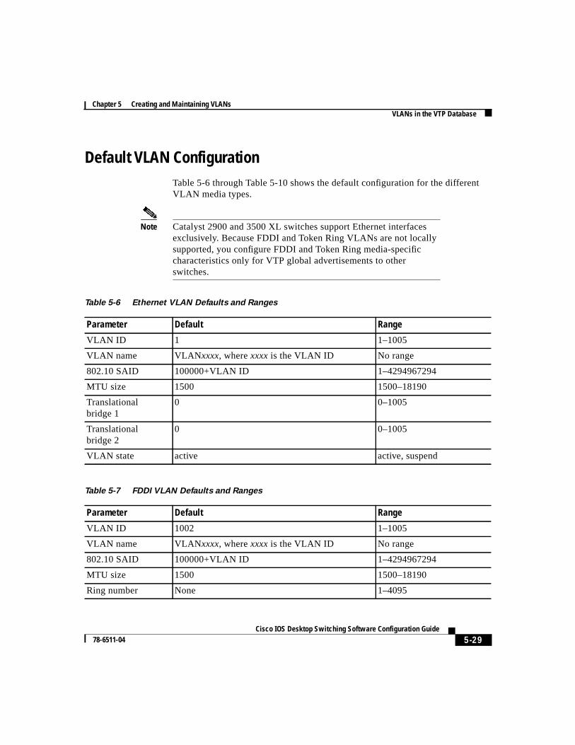
Default VLAN ConfigurationTable 5-6 through Table 5-10 shows the default configuration for the differentVLAN media types.
Note Catalyst 2900 and 3500 XL switches support Ethernet interfacesexclusively. Because FDDI and Token Ring VLANs are not locallysupported, you configure FDDI and Token Ring media-specificcharacteristics only for VTP global advertisements to otherswitches.
Table 5-6 Ethernet VLAN Defaults and Ranges
Parameter Default Range
VLAN ID 1 1–1005
VLAN name VLANxxxx, wherexxxx is the VLAN ID No range
802.10 SAID 100000+VLAN ID 1–4294967294
MTU size 1500 1500–18190
Translationalbridge 1
0 0–1005
Translationalbridge 2
0 0–1005
VLAN state active active, suspend
Table 5-7 FDDI VLAN Defaults and Ranges
Parameter Default Range
VLAN ID 1002 1–1005
VLAN name VLANxxxx, wherexxxx is the VLAN ID No range
802.10 SAID 100000+VLAN ID 1–4294967294
MTU size 1500 1500–18190
Ring number None 1–4095
Chapter 5 Creating and Maintaining VLANsVLANs in the VTP Database
5-30Cisco IOS Desktop Switching Software Configuration Guide
78-6511-04
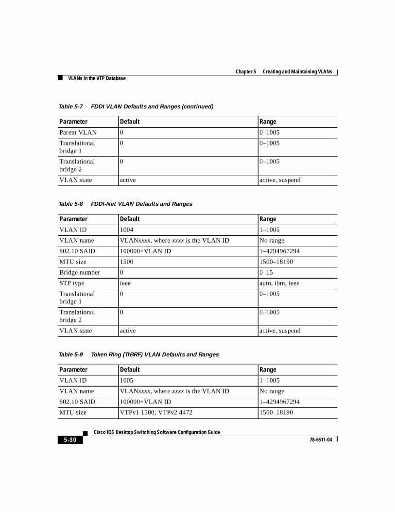
Parent VLAN 0 0–1005
Translationalbridge 1
0 0–1005
Translationalbridge 2
0 0–1005
VLAN state active active, suspend
Table 5-8 FDDI-Net VLAN Defaults and Ranges
Parameter Default Range
VLAN ID 1004 1–1005
VLAN name VLANxxxx, wherexxxx is the VLAN ID No range
802.10 SAID 100000+VLAN ID 1–4294967294
MTU size 1500 1500–18190
Bridge number 0 0–15
STP type ieee auto, ibm, ieee
Translationalbridge 1
0 0–1005
Translationalbridge 2
0 0–1005
VLAN state active active, suspend
Table 5-9 Token Ring (TrBRF) VLAN Defaults and Ranges
Parameter Default Range
VLAN ID 1005 1–1005
VLAN name VLANxxxx, wherexxxx is the VLAN ID No range
802.10 SAID 100000+VLAN ID 1–4294967294
MTU size VTPv1 1500; VTPv2 4472 1500–18190
Table 5-7 FDDI VLAN Defaults and Ranges (continued)
Parameter Default Range
5-31 Cisco IOS Desktop Switching Software Configuration Guide
78-6511-04
Chapter 5 Creating and Maintaining VLANsVLANs in the VTP Database
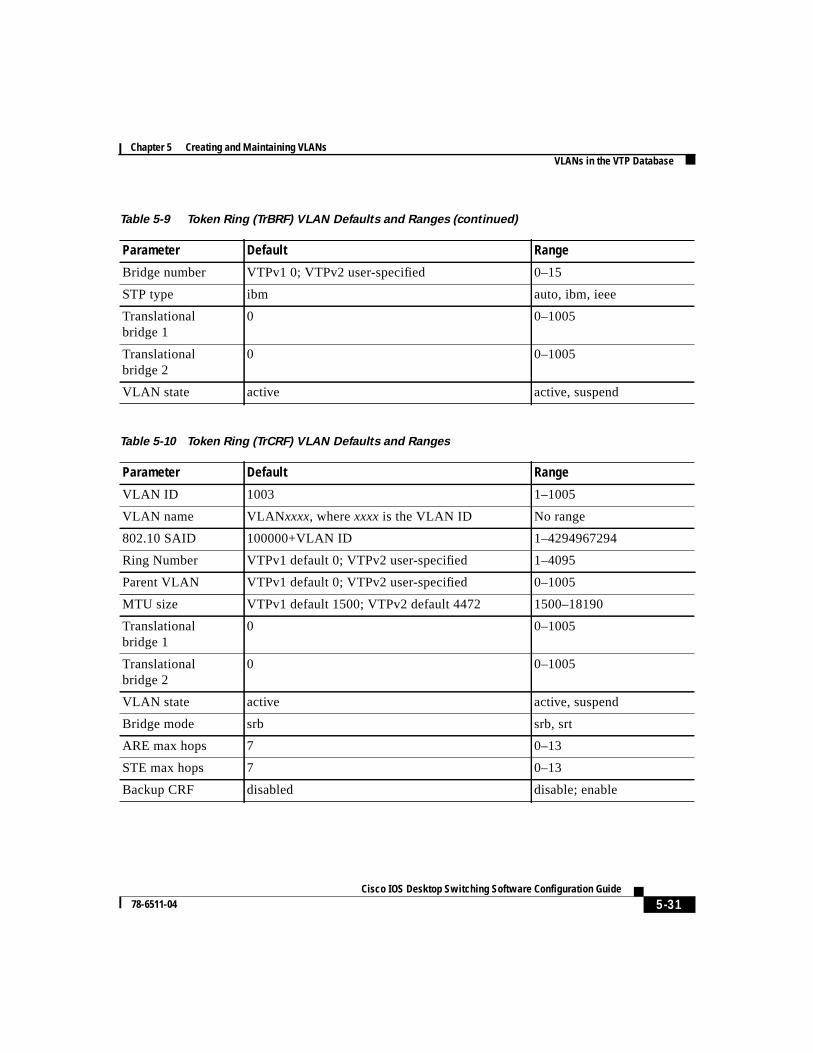
Bridge number VTPv1 0; VTPv2 user-specified 0–15
STP type ibm auto, ibm, ieee
Translationalbridge 1
0 0–1005
Translationalbridge 2
0 0–1005
VLAN state active active, suspend
Table 5-10 Token Ring (TrCRF) VLAN Defaults and Ranges
Parameter Default Range
VLAN ID 1003 1–1005
VLAN name VLANxxxx, wherexxxxis the VLAN ID No range
802.10 SAID 100000+VLAN ID 1–4294967294
Ring Number VTPv1 default 0; VTPv2 user-specified 1–4095
Parent VLAN VTPv1 default 0; VTPv2 user-specified 0–1005
MTU size VTPv1 default 1500; VTPv2 default 4472 1500–18190
Translationalbridge 1
0 0–1005
Translationalbridge 2
0 0–1005
VLAN state active active, suspend
Bridge mode srb srb, srt
ARE max hops 7 0–13
STE max hops 7 0–13
Backup CRF disabled disable; enable
Table 5-9 Token Ring (TrBRF) VLAN Defaults and Ranges (continued)
Parameter Default Range
Chapter 5 Creating and Maintaining VLANsVLANs in the VTP Database
5-32Cisco IOS Desktop Switching Software Configuration Guide
78-6511-04
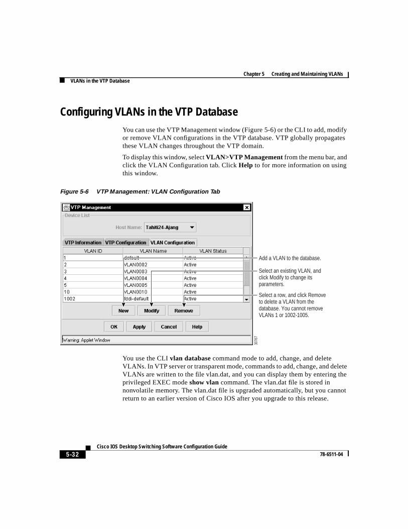
Configuring VLANs in the VTP DatabaseYou can use the VTP Management window (Figure 5-6) or the CLI to add, modifyor remove VLAN configurations in the VTP database. VTP globally propagatesthese VLAN changes throughout the VTP domain.
To display this window, selectVLAN>VTP Management from the menu bar, andclick the VLAN Configuration tab. ClickHelp to for more information on usingthis window.
Figure 5-6 VTP Management: VLAN Configuration Tab
You use the CLIvlan database command mode to add, change, and deleteVLANs. In VTP server or transparent mode, commands to add, change, and deleteVLANs are written to the file vlan.dat, and you can display them by entering theprivileged EXEC modeshow vlan command. The vlan.dat file is stored innonvolatile memory. The vlan.dat file is upgraded automatically, but you cannotreturn to an earlier version of Cisco IOS after you upgrade to this release.
Add a VLAN to the database.
Select an existing VLAN, and click Modify to change its parameters.
Select a row, and click Remove to delete a VLAN from the database. You cannot remove VLANs 1 or 1002-1005.
3076
7
5-33 Cisco IOS Desktop Switching Software Configuration Guide
78-6511-04
Chapter 5 Creating and Maintaining VLANsVLANs in the VTP Database
Caution You can cause inconsistency in the VLAN database if you attempt tomanually delete the vlan.dat file. If you want to modify the VLANconfiguration or VTP, use the VLAN database commands describedin theCisco IOS Desktop Switching Command Reference (onlineonly).
You use the interface configuration command mode to define the port membershipmode and add and remove ports from VLAN. The results of these commands arewritten to the running-configuration file, and you can display the file by enteringthe privileged EXEC modeshow running-config command.
Note VLANs can be configured to support a number of parameters that arenot discussed in detail in this section. For complete information onthe commands and parameters that control VLAN configuration,refer to theCisco IOS Desktop Switching Command Reference(online only).
Chapter 5 Creating and Maintaining VLANsVLANs in the VTP Database
5-34Cisco IOS Desktop Switching Software Configuration Guide
78-6511-04
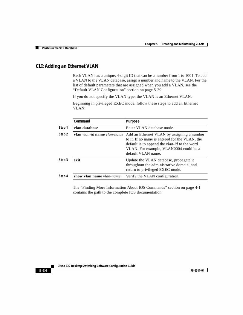
CLI: Adding an Ethernet VLAN
Each VLAN has a unique, 4-digit ID that can be a number from 1 to 1001. To adda VLAN to the VLAN database, assign a number and name to the VLAN. For thelist of default parameters that are assigned when you add a VLAN, see the“Default VLAN Configuration” section on page 5-29.
If you do not specify the VLAN type, the VLAN is an Ethernet VLAN.
Beginning in privileged EXEC mode, follow these steps to add an EthernetVLAN:
The “Finding More Information About IOS Commands” section on page 4-1contains the path to the complete IOS documentation.
Command Purpose
Step 1 vlan database Enter VLAN database mode.
Step 2 vlan vlan-id namevlan-name Add an Ethernet VLAN by assigning a numberto it. If no name is entered for the VLAN, thedefault is to append thevlan-id to the wordVLAN. For example, VLAN0004 could be adefault VLAN name.
Step 3 exit Update the VLAN database, propagate itthroughout the administrative domain, andreturn to privileged EXEC mode.
Step 4 show vlan namevlan-name Verify the VLAN configuration.
5-35 Cisco IOS Desktop Switching Software Configuration Guide
78-6511-04
Chapter 5 Creating and Maintaining VLANsVLANs in the VTP Database
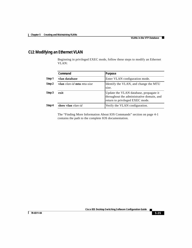
CLI: Modifying an Ethernet VLAN
Beginning in privileged EXEC mode, follow these steps to modify an EthernetVLAN:
The “Finding More Information About IOS Commands” section on page 4-1contains the path to the complete IOS documentation.
Command Purpose
Step 1 vlan database Enter VLAN configuration mode.
Step 2 vlan vlan-id mtu mtu-size Identify the VLAN, and change the MTUsize.
Step 3 exit Update the VLAN database, propagate itthroughout the administrative domain, andreturn to privileged EXEC mode.
Step 4 show vlanvlan-id Verify the VLAN configuration.
Chapter 5 Creating and Maintaining VLANsVLANs in the VTP Database
5-36Cisco IOS Desktop Switching Software Configuration Guide
78-6511-04
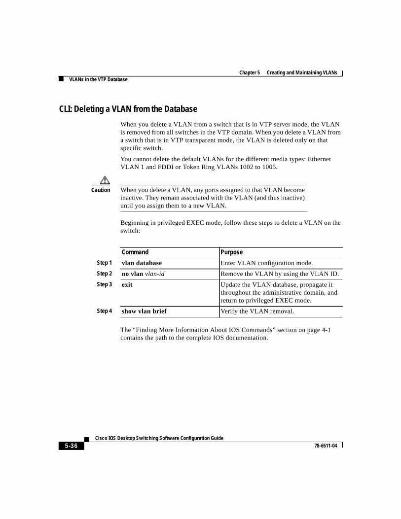
CLI: Deleting a VLAN from the Database
When you delete a VLAN from a switch that is in VTP server mode, the VLANis removed from all switches in the VTP domain. When you delete a VLAN froma switch that is in VTP transparent mode, the VLAN is deleted only on thatspecific switch.
You cannot delete the default VLANs for the different media types: EthernetVLAN 1 and FDDI or Token Ring VLANs 1002 to 1005.
Caution When you delete a VLAN, any ports assigned to that VLAN becomeinactive. They remain associated with the VLAN (and thus inactive)until you assign them to a new VLAN.
Beginning in privileged EXEC mode, follow these steps to delete a VLAN on theswitch:
The “Finding More Information About IOS Commands” section on page 4-1contains the path to the complete IOS documentation.
Command Purpose
Step 1 vlan database Enter VLAN configuration mode.
Step 2 no vlan vlan-id Remove the VLAN by using the VLAN ID.
Step 3 exit Update the VLAN database, propagate itthroughout the administrative domain, andreturn to privileged EXEC mode.
Step 4 show vlan brief Verify the VLAN removal.
5-37 Cisco IOS Desktop Switching Software Configuration Guide
78-6511-04
Chapter 5 Creating and Maintaining VLANsVLANs in the VTP Database
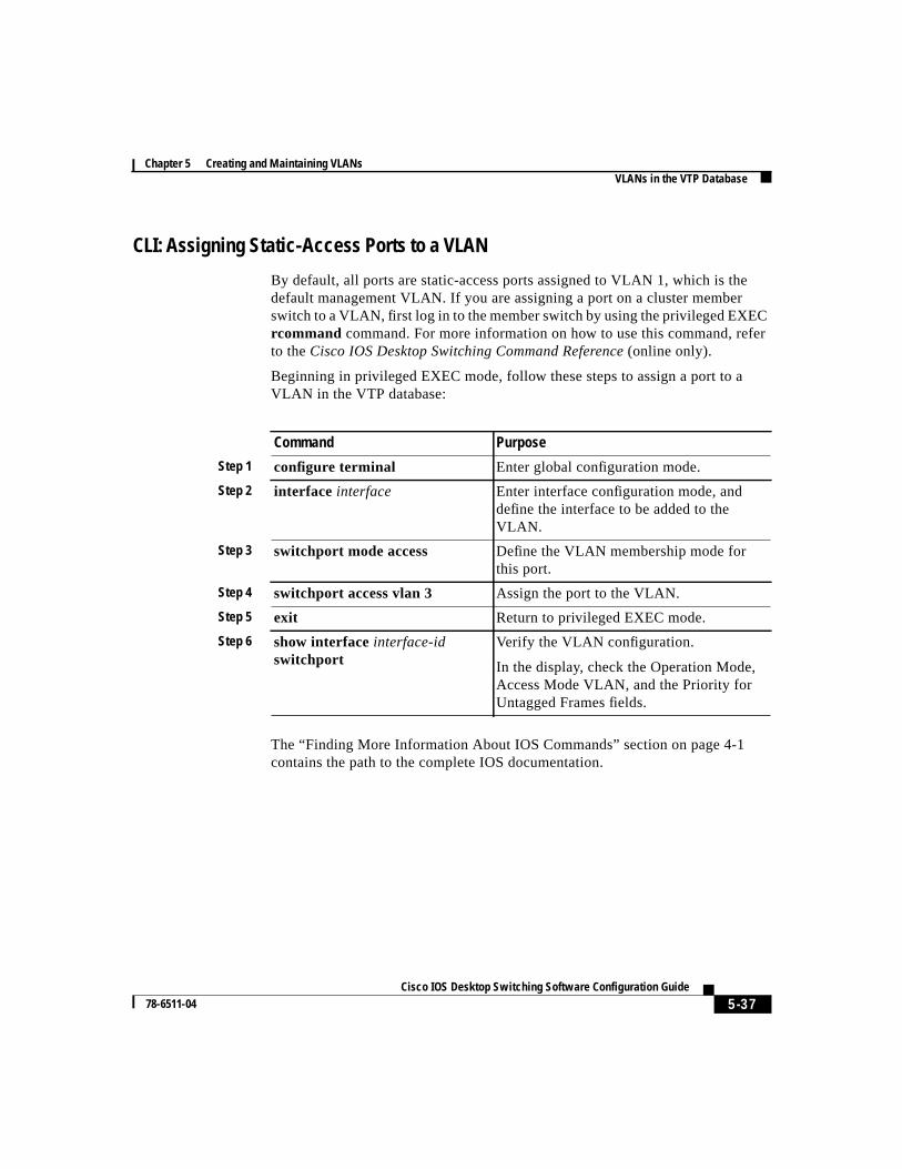
CLI: Assigning Static-Access Ports to a VLAN
By default, all ports are static-access ports assigned to VLAN 1, which is thedefault management VLAN. If you are assigning a port on a cluster memberswitch to a VLAN, first log in to the member switch by using the privileged EXECrcommand command. For more information on how to use this command, referto theCisco IOS Desktop Switching Command Reference(online only).
Beginning in privileged EXEC mode, follow these steps to assign a port to aVLAN in the VTP database:
The “Finding More Information About IOS Commands” section on page 4-1contains the path to the complete IOS documentation.
Command Purpose
Step 1 configure terminal Enter global configuration mode.
Step 2 interface interface Enter interface configuration mode, anddefine the interface to be added to theVLAN.
Step 3 switchport mode access Define the VLAN membership mode forthis port.
Step 4 switchport access vlan 3 Assign the port to the VLAN.
Step 5 exit Return to privileged EXEC mode.
Step 6 show interfaceinterface-idswitchport
Verify the VLAN configuration.
In the display, check the Operation Mode,Access Mode VLAN, and the Priority forUntagged Frames fields.
Chapter 5 Creating and Maintaining VLANsHow VLAN Trunks Work
5-38Cisco IOS Desktop Switching Software Configuration Guide
78-6511-04
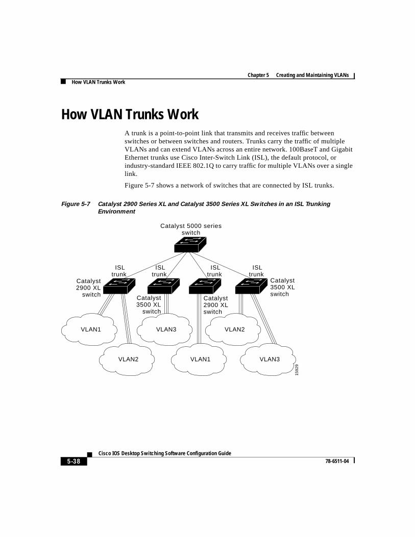
How VLAN Trunks WorkA trunk is a point-to-point link that transmits and receives traffic betweenswitches or between switches and routers. Trunks carry the traffic of multipleVLANs and can extend VLANs across an entire network. 100BaseT and GigabitEthernet trunks use Cisco Inter-Switch Link (ISL), the default protocol, orindustry-standard IEEE 802.1Q to carry traffic for multiple VLANs over a singlelink.
Figure 5-7 shows a network of switches that are connected by ISL trunks.
Figure 5-7 Catalyst 2900 Series XL and Catalyst 3500 Series XL Switches in an ISL Trunking
Environment
Catalyst 5000 seriesswitch
Catalyst2900 XL
switch Catalyst3500 XL
switch
Catalyst2900 XL switch
Catalyst 3500 XLswitch
VLAN2
VLAN3VLAN1
VLAN1
VLAN2
VLAN3
ISLtrunk
ISLtrunk
ISLtrunk
ISLtrunk
1592
9
5-39 Cisco IOS Desktop Switching Software Configuration Guide
78-6511-04
Chapter 5 Creating and Maintaining VLANsHow VLAN Trunks Work
IEEE 802.1Q Configuration ConsiderationsIEEE 802.1Q trunks impose some limitations on the trunking strategy for anetwork. The following restrictions apply when using 802.1Q trunks:
• Make sure the native VLAN for an 802.1Q trunk is the same on both ends ofthe trunk link. If the native VLAN on one end of the trunk is different fromthe native VLAN on the other end, spanning-tree loops might result.
• Disabling STP on the native VLAN of an 802.1Q trunk without disabling STPon every VLAN in the network can potentially cause STP loops. Werecommend that you leave STP enabled on the native VLAN of an 802.1Qtrunk or disable STP on every VLAN in the network. Make sure your networkis loop-free before disabling STP.
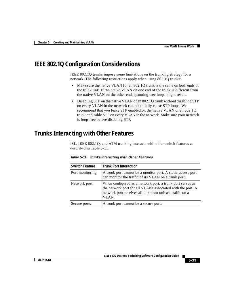
Trunks Interacting with Other FeaturesISL, IEEE 802.1Q, and ATM trunking interacts with other switch features asdescribed in Table 5-11.
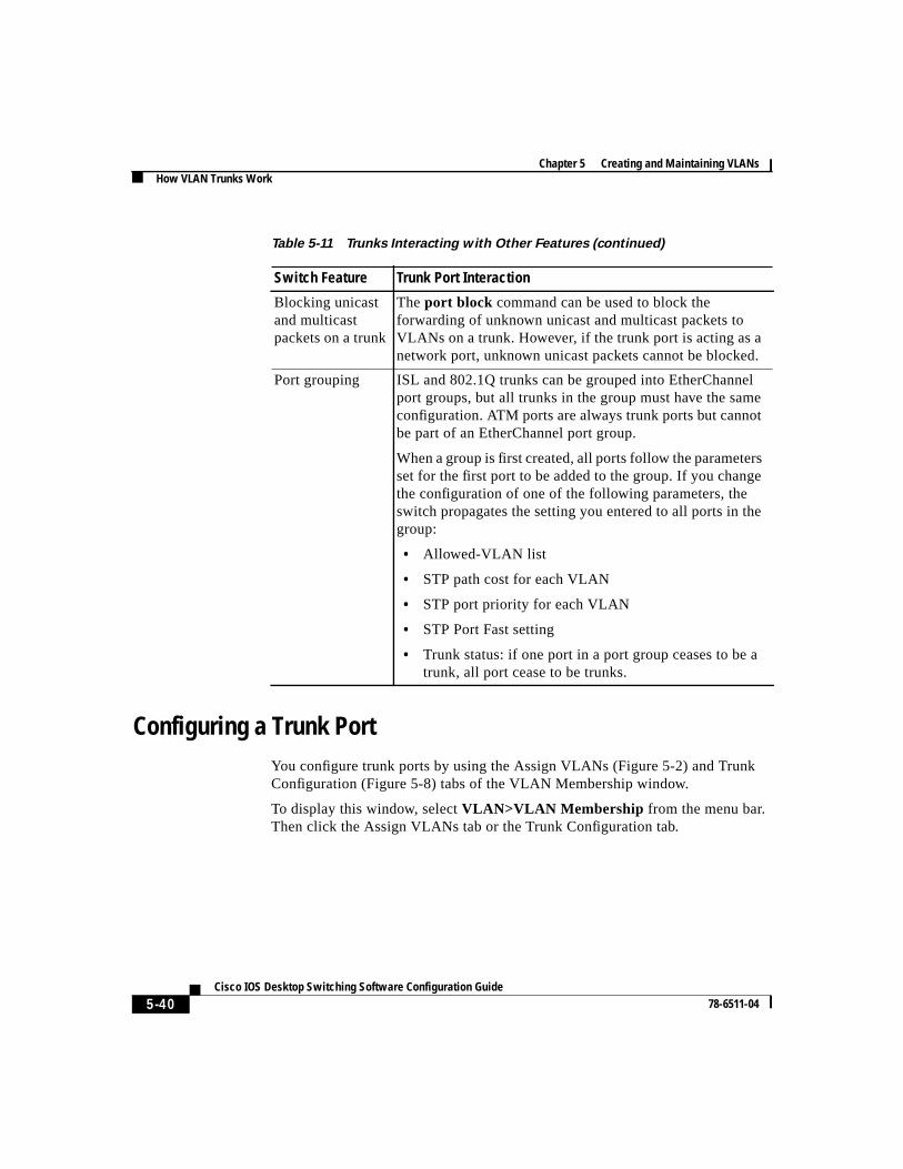
Table 5-11 Trunks Interacting with Other Features
Switch Feature Trunk Port Interaction
Port monitoring A trunk port cannot be a monitor port. A static-access portcan monitor the traffic of its VLAN on a trunk port.
Network port When configured as a network port, a trunk port serves asthe network port for all VLANs associated with the port. Anetwork port receives all unknown unicast traffic on aVLAN.
Secure ports A trunk port cannot be a secure port.
Chapter 5 Creating and Maintaining VLANsHow VLAN Trunks Work
5-40Cisco IOS Desktop Switching Software Configuration Guide
78-6511-04
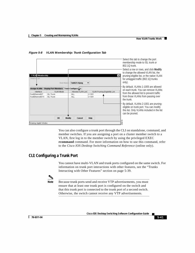
Configuring a Trunk PortYou configure trunk ports by using the Assign VLANs (Figure 5-2) and TrunkConfiguration (Figure 5-8) tabs of the VLAN Membership window.
To display this window, selectVLAN>VLAN Membership from the menu bar.Then click the Assign VLANs tab or the Trunk Configuration tab.
Blocking unicastand multicastpackets on a trunk
Theport block command can be used to block theforwarding of unknown unicast and multicast packets toVLANs on a trunk. However, if the trunk port is acting as anetwork port, unknown unicast packets cannot be blocked.
Port grouping ISL and 802.1Q trunks can be grouped into EtherChannelport groups, but all trunks in the group must have the sameconfiguration. ATM ports are always trunk ports but cannotbe part of an EtherChannel port group.
When a group is first created, all ports follow the parametersset for the first port to be added to the group. If you changethe configuration of one of the following parameters, theswitch propagates the setting you entered to all ports in thegroup:
• Allowed-VLAN list
• STP path cost for each VLAN
• STP port priority for each VLAN
• STP Port Fast setting
• Trunk status: if one port in a port group ceases to be atrunk, all port cease to be trunks.
Table 5-11 Trunks Interacting with Other Features (continued)
Switch Feature Trunk Port Interaction
5-41 Cisco IOS Desktop Switching Software Configuration Guide
78-6511-04
Chapter 5 Creating and Maintaining VLANsHow VLAN Trunks Work
Figure 5-8 VLAN Membership: Trunk Configuration Tab
You can also configure a trunk port through the CLI on standalone, command, andmember switches. If you are assigning a port on a cluster member switch to aVLAN, first log in to the member switch by using the privileged EXECrcommand command. For more information on how to use this command, referto theCisco IOS Desktop Switching Command Reference (online only).
CLI: Configuring a Trunk Port
You cannot have multi-VLAN and trunk ports configured on the same switch. Forinformation on trunk port interactions with other features, see the “TrunksInteracting with Other Features” section on page 5-39.
Note Because trunk ports send and receive VTP advertisements, you mustensure that at least one trunk port is configured on the switch andthat this trunk port is connected to the trunk port of a second switch.Otherwise, the switch cannot receive any VTP advertisements.
2967
6
Select this tab to change the port membership mode to ISL trunk or 802.1Q trunk.
By default, VLANs 1-1005 are allowed on each trunk. You can remove VLANs from the allowed list to prevent traffic from those VLANs from passing over the trunk.
Select a row or rows, and click Modify to change the allowed-VLAN list, the pruning-eligible list, or the native VLAN for untagged traffic (802.1Q trunks only).
By default, VLANs 2-1001 are pruning- eligible on trunk port. You can modify this list. Only VLANs included in the list can be pruned.
Chapter 5 Creating and Maintaining VLANsHow VLAN Trunks Work
5-42Cisco IOS Desktop Switching Software Configuration Guide
78-6511-04
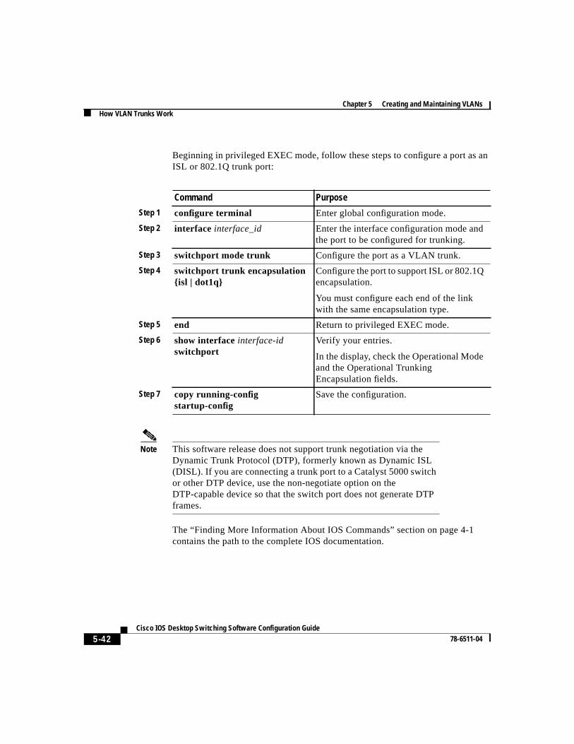
Beginning in privileged EXEC mode, follow these steps to configure a port as anISL or 802.1Q trunk port:
Note This software release does not support trunk negotiation via theDynamic Trunk Protocol (DTP), formerly known as Dynamic ISL(DISL). If you are connecting a trunk port to a Catalyst 5000 switchor other DTP device, use the non-negotiate option on theDTP-capable device so that the switch port does not generate DTPframes.
The “Finding More Information About IOS Commands” section on page 4-1contains the path to the complete IOS documentation.
Command Purpose
Step 1 configure terminal Enter global configuration mode.
Step 2 interface interface_id Enter the interface configuration mode andthe port to be configured for trunking.
Step 3 switchport mode trunk Configure the port as a VLAN trunk.
Step 4 switchport trunk encapsulation{isl | dot1q}
Configure the port to support ISL or 802.1Qencapsulation.
You must configure each end of the linkwith the same encapsulation type.
Step 5 end Return to privileged EXEC mode.
Step 6 show interfaceinterface-idswitchport
Verify your entries.
In the display, check the Operational Modeand the Operational TrunkingEncapsulation fields.
Step 7 copy running-configstartup-config
Save the configuration.
5-43 Cisco IOS Desktop Switching Software Configuration Guide
78-6511-04
Chapter 5 Creating and Maintaining VLANsHow VLAN Trunks Work
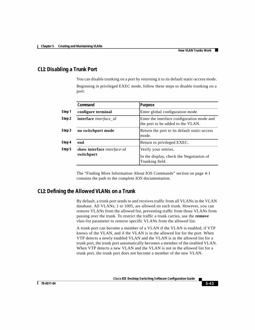
CLI: Disabling a Trunk Port
You can disable trunking on a port by returning it to its default static-access mode.
Beginning in privileged EXEC mode, follow these steps to disable trunking on aport:
The “Finding More Information About IOS Commands” section on page 4-1contains the path to the complete IOS documentation.
CLI: Defining the Allowed VLANs on a Trunk
By default, a trunk port sends to and receives traffic from all VLANs in the VLANdatabase. All VLANs, 1 to 1005, are allowed on each trunk. However, you canremove VLANs from the allowed list, preventing traffic from those VLANs frompassing over the trunk. To restrict the traffic a trunk carries, use theremovevlan-list parameter to remove specific VLANs from the allowed list.
A trunk port can become a member of a VLAN if the VLAN is enabled, if VTPknows of the VLAN, and if the VLAN is in the allowed list for the port. WhenVTP detects a newly enabled VLAN and the VLAN is in the allowed list for atrunk port, the trunk port automatically becomes a member of the enabled VLAN.When VTP detects a new VLAN and the VLAN is not in the allowed list for atrunk port, the trunk port does not become a member of the new VLAN.
Command Purpose
Step 1 configure terminal Enter global configuration mode.
Step 2 interface interface_id Enter the interface configuration mode andthe port to be added to the VLAN.
Step 3 no switchport mode Return the port to its default static-accessmode.
Step 4 end Return to privileged EXEC.
Step 5 show interfaceinterface-idswitchport
Verify your entries.
In the display, check the Negotiation ofTrunking field.
Chapter 5 Creating and Maintaining VLANsHow VLAN Trunks Work
5-44Cisco IOS Desktop Switching Software Configuration Guide
78-6511-04
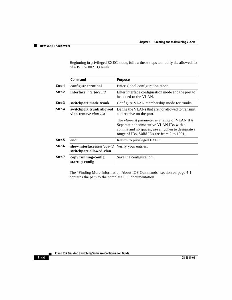
Beginning in privileged EXEC mode, follow these steps to modify the allowed listof a ISL or 802.1Q trunk:
The “Finding More Information About IOS Commands” section on page 4-1contains the path to the complete IOS documentation.
Command Purpose
Step 1 configure terminal Enter global configuration mode.
Step 2 interface interface_id Enter interface configuration mode and the port tobe added to the VLAN.
Step 3 switchport mode trunk Configure VLAN membership mode for trunks.
Step 4 switchport trunk allowedvlan removevlan-list
Define the VLANs that arenotallowed to transmitand receive on the port.
Thevlan-list parameter is a range of VLAN IDsSeparate nonconsecutive VLAN IDs with acomma and no spaces; use a hyphen to designate arange of IDs. Valid IDs are from 2 to 1001.
Step 5 end Return to privileged EXEC.
Step 6 show interfaceinterface-idswitchport allowed-vlan
Verify your entries.
Step 7 copy running-configstartup-config
Save the configuration.
5-45 Cisco IOS Desktop Switching Software Configuration Guide
78-6511-04
Chapter 5 Creating and Maintaining VLANsHow VLAN Trunks Work
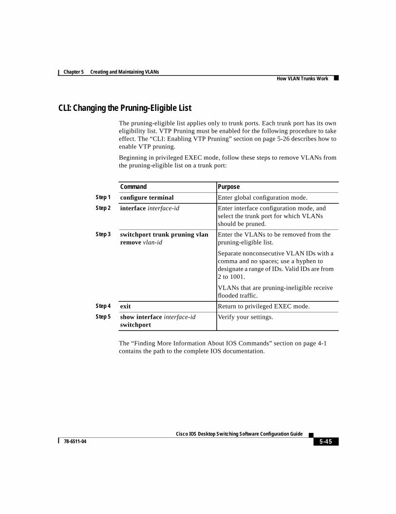
CLI: Changing the Pruning-Eligible List
The pruning-eligible list applies only to trunk ports. Each trunk port has its owneligibility list. VTP Pruning must be enabled for the following procedure to takeeffect. The “CLI: Enabling VTP Pruning” section on page 5-26 describes how toenable VTP pruning.
Beginning in privileged EXEC mode, follow these steps to remove VLANs fromthe pruning-eligible list on a trunk port:
The “Finding More Information About IOS Commands” section on page 4-1contains the path to the complete IOS documentation.
Command Purpose
Step 1 configure terminal Enter global configuration mode.
Step 2 interface interface-id Enter interface configuration mode, andselect the trunk port for which VLANsshould be pruned.
Step 3 switchport trunk pruning vlanremovevlan-id
Enter the VLANs to be removed from thepruning-eligible list.
Separate nonconsecutive VLAN IDs with acomma and no spaces; use a hyphen todesignate a range of IDs. Valid IDs are from2 to 1001.
VLANs that are pruning-ineligible receiveflooded traffic.
Step 4 exit Return to privileged EXEC mode.
Step 5 show interfaceinterface-idswitchport
Verify your settings.
Chapter 5 Creating and Maintaining VLANsHow VLAN Trunks Work
5-46Cisco IOS Desktop Switching Software Configuration Guide
78-6511-04
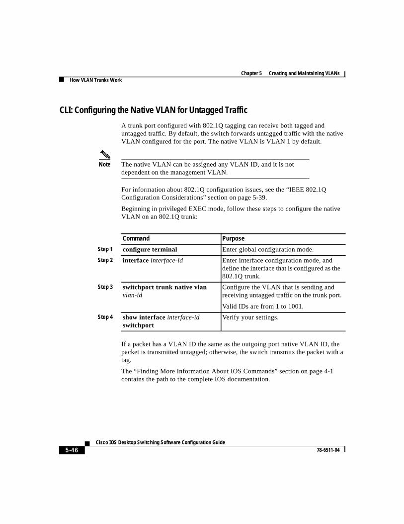
CLI: Configuring the Native VLAN for Untagged Traffic
A trunk port configured with 802.1Q tagging can receive both tagged anduntagged traffic. By default, the switch forwards untagged traffic with the nativeVLAN configured for the port. The native VLAN is VLAN 1 by default.
Note The native VLAN can be assigned any VLAN ID, and it is notdependent on the management VLAN.
For information about 802.1Q configuration issues, see the “IEEE 802.1QConfiguration Considerations” section on page 5-39.
Beginning in privileged EXEC mode, follow these steps to configure the nativeVLAN on an 802.1Q trunk:
If a packet has a VLAN ID the same as the outgoing port native VLAN ID, thepacket is transmitted untagged; otherwise, the switch transmits the packet with atag.
The “Finding More Information About IOS Commands” section on page 4-1contains the path to the complete IOS documentation.
Command Purpose
Step 1 configure terminal Enter global configuration mode.
Step 2 interface interface-id Enter interface configuration mode, anddefine the interface that is configured as the802.1Q trunk.
Step 3 switchport trunk native vlanvlan-id
Configure the VLAN that is sending andreceiving untagged traffic on the trunk port.
Valid IDs are from 1 to 1001.
Step 4 show interfaceinterface-idswitchport
Verify your settings.
5-47 Cisco IOS Desktop Switching Software Configuration Guide
78-6511-04
Chapter 5 Creating and Maintaining VLANsHow VLAN Trunks Work
Configuring 802.1p Class of ServiceThe 2900 XL and 3500 XL switches provide QoS-based IEEE 802.1p class ofservice (CoS) values. QoS uses classification and scheduling to transmit networktraffic from the switch in a predictable manner. QoS classifies frames by assigningpriority-indexed CoS values to them and gives preference to higher-priority trafficsuch as telephone calls.
How Class of Service Works
Before you set up 802.1p CoS on a 2900 or 3500 XL switch that operates with theCatalyst 6000 family of switches, refer to the Catalyst 6000 documentation. Thereare differences in the 802.1p implementation, and they should be understood toensure compatibility.
Port Priority
Frames received from users in the administratively-defined VLANs are classifiedor taggedfor transmission to other devices. Based on rules you define, a uniqueidentifier (the tag) is inserted in each frame header before it is forwarded. The tagis examined and understood by each device before any broadcasts ortransmissions to other switches, routers, or end stations. When the frame reachesthe last switch or router, the tag is removed before the frame is transmitted to thetarget end station. VLANs that are assigned on trunk or access ports withoutidentification or a tag are callednative or untagged frames.
For ISL or IEEE 802.1Q frames with tag information, the priority value from theheader frame is used. For native frames, the default priority of the input port is used.
Port Scheduling
Each port on the switch has a single receive queue buffer (theingressport) forincoming traffic. When an untagged frame arrives, it is assigned the value of theport as its port default priority. You assign this value by using the CLI or CMSsoftware. A tagged frame continues to use its assigned CoS value when it passesthrough the ingress port.
Chapter 5 Creating and Maintaining VLANsHow VLAN Trunks Work
5-48Cisco IOS Desktop Switching Software Configuration Guide
78-6511-04
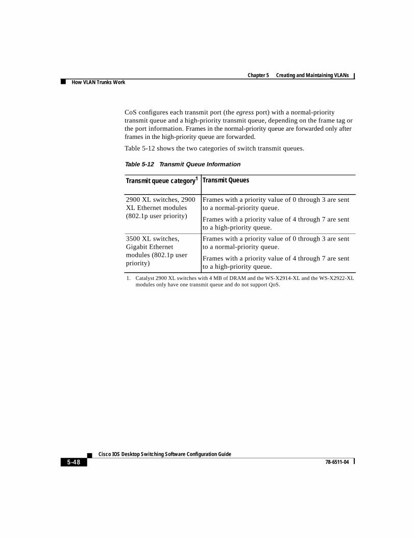
CoS configures each transmit port (theegressport) with a normal-prioritytransmit queue and a high-priority transmit queue, depending on the frame tag orthe port information.Frames in the normal-priority queue are forwarded only afterframes in the high-priority queue are forwarded.
Table 5-12 shows the two categories of switch transmit queues.
Table 5-12 Transmit Queue Information
Transmit queue category1
1. Catalyst 2900 XL switches with 4 MB of DRAM and the WS-X2914-XL and the WS-X2922-XLmodules only have one transmit queue and do not support QoS.
Transmit Queues
2900 XL switches, 2900XL Ethernet modules(802.1p user priority)
Frames with a priority value of 0 through 3 are sentto a normal-priority queue.
Frames with a priority value of 4 through 7 are sentto a high-priority queue.
3500 XL switches,Gigabit Ethernetmodules (802.1p userpriority)
Frames with a priority value of 0 through 3 are sentto a normal-priority queue.
Frames with a priority value of 4 through 7 are sentto a high-priority queue.
5-49 Cisco IOS Desktop Switching Software Configuration Guide
78-6511-04
Chapter 5 Creating and Maintaining VLANsHow VLAN Trunks Work
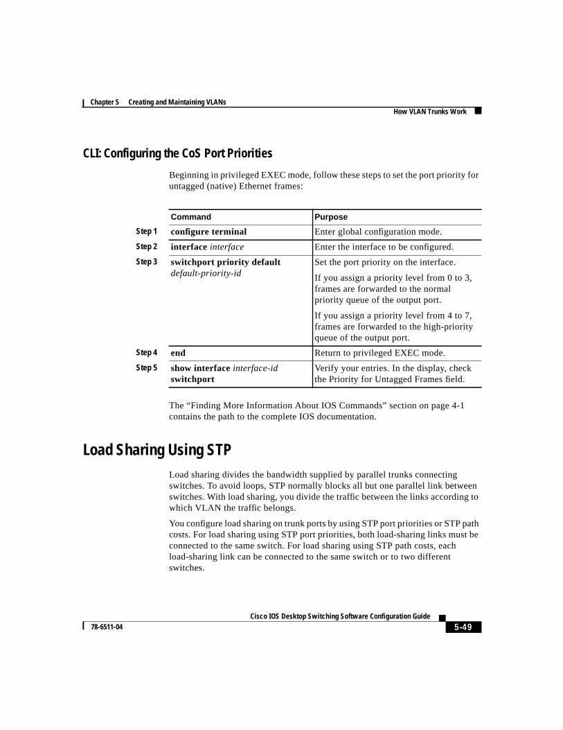
CLI: Configuring the CoS Port Priorities
Beginning in privileged EXEC mode, follow these steps to set the port priority foruntagged (native) Ethernet frames:
The “Finding More Information About IOS Commands” section on page 4-1contains the path to the complete IOS documentation.
Load Sharing Using STPLoad sharing divides the bandwidth supplied by parallel trunks connectingswitches. To avoid loops, STP normally blocks all but one parallel link betweenswitches. With load sharing, you divide the traffic between the links according towhich VLAN the traffic belongs.
You configure load sharing on trunk ports by using STP port priorities or STP pathcosts. For load sharing using STP port priorities, both load-sharing links must beconnected to the same switch. For load sharing using STP path costs, eachload-sharing link can be connected to the same switch or to two differentswitches.
Command Purpose
Step 1 configure terminal Enter global configuration mode.
Step 2 interface interface Enter the interface to be configured.
Step 3 switchport priority defaultdefault-priority-id
Set the port priority on the interface.
If you assign a priority level from 0 to 3,frames are forwarded to the normalpriority queue of the output port.
If you assign a priority level from 4 to 7,frames are forwarded to the high-priorityqueue of the output port.
Step 4 end Return to privileged EXEC mode.
Step 5 show interfaceinterface-idswitchport
Verify your entries. In the display, checkthe Priority for Untagged Frames field.
Chapter 5 Creating and Maintaining VLANsHow VLAN Trunks Work
5-50Cisco IOS Desktop Switching Software Configuration Guide
78-6511-04
You can change STP port parameters by using the Port Parameters tab of theSpanning Tree Protocol window or by using the CLI. To display this window,selectDevice>Spanning-Tree Protocol from the menu bar. Then click thePortParameters tab.
For more information about the STP window, see the “Configuring the SpanningTree Protocol” section on page 4-62, or consult the online help in the application.
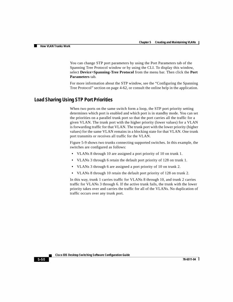
Load Sharing Using STP Port Priorities
When two ports on the same switch form a loop, the STP port priority settingdetermines which port is enabled and which port is in standby mode. You can setthe priorities on a parallel trunk port so that the port carries all the traffic for agiven VLAN. The trunk port with the higher priority (lower values) for a VLANis forwarding traffic for that VLAN. The trunk port with the lower priority (highervalues) for the same VLAN remains in a blocking state for that VLAN. One trunkport transmits or receives all traffic for the VLAN.
Figure 5-9 shows two trunks connecting supported switches. In this example, theswitches are configured as follows:
• VLANs 8 through 10 are assigned a port priority of 10 on trunk 1.
• VLANs 3 through 6 retain the default port priority of 128 on trunk 1.
• VLANs 3 through 6 are assigned a port priority of 10 on trunk 2.
• VLANs 8 through 10 retain the default port priority of 128 on trunk 2.
In this way, trunk 1 carries traffic for VLANs 8 through 10, and trunk 2 carriestraffic for VLANs 3 through 6. If the active trunk fails, the trunk with the lowerpriority takes over and carries the traffic for all of the VLANs. No duplication oftraffic occurs over any trunk port.
5-51 Cisco IOS Desktop Switching Software Configuration Guide
78-6511-04
Chapter 5 Creating and Maintaining VLANsHow VLAN Trunks Work
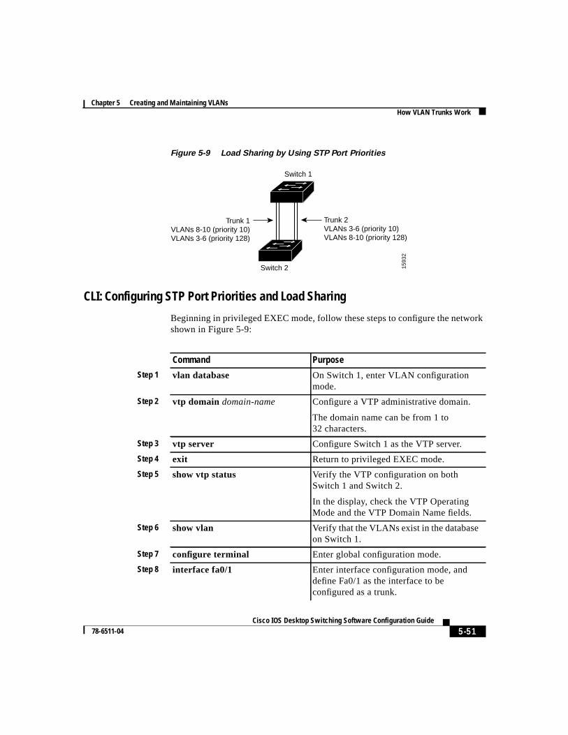
Figure 5-9 Load Sharing by Using STP Port Priorities
CLI: Configuring STP Port Priorities and Load Sharing
Beginning in privileged EXEC mode, follow these steps to configure the networkshown in Figure 5-9:
1593
2
Switch 1
Switch 2
Trunk 2VLANs 3-6 (priority 10)VLANs 8-10 (priority 128)
Trunk 1VLANs 8-10 (priority 10)VLANs 3-6 (priority 128)
Command Purpose
Step 1 vlan database On Switch 1, enter VLAN configurationmode.
Step 2 vtp domain domain-name Configure a VTP administrative domain.
The domain name can be from 1 to32 characters.
Step 3 vtp server Configure Switch 1 as the VTP server.
Step 4 exit Return to privileged EXEC mode.
Step 5 show vtp status Verify the VTP configuration on bothSwitch 1 and Switch 2.
In the display, check the VTP OperatingMode and the VTP Domain Name fields.
Step 6 show vlan Verify that the VLANs exist in the databaseon Switch 1.
Step 7 configure terminal Enter global configuration mode.
Step 8 interface fa0/1 Enter interface configuration mode, anddefine Fa0/1 as the interface to beconfigured as a trunk.
Chapter 5 Creating and Maintaining VLANsHow VLAN Trunks Work
5-52Cisco IOS Desktop Switching Software Configuration Guide
78-6511-04
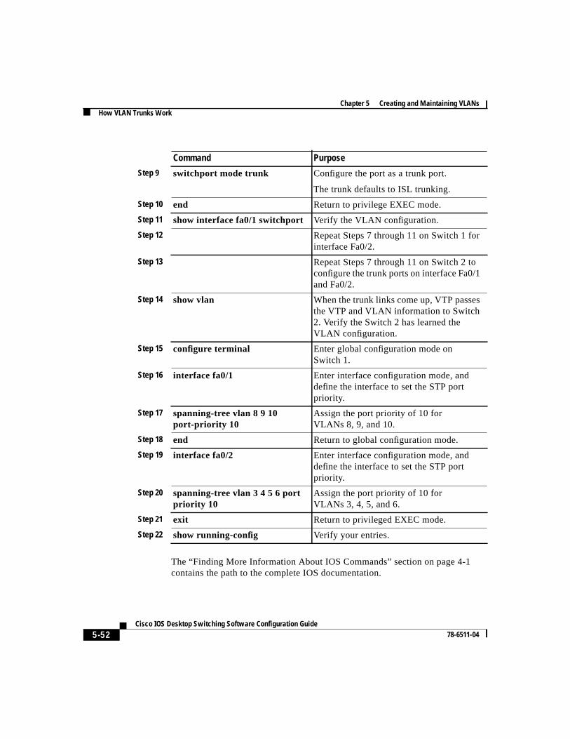
The “Finding More Information About IOS Commands” section on page 4-1contains the path to the complete IOS documentation.
Step 9 switchport mode trunk Configure the port as a trunk port.
The trunk defaults to ISL trunking.
Step 10 end Return to privilege EXEC mode.
Step 11 show interface fa0/1 switchport Verify the VLAN configuration.
Step 12 Repeat Steps 7 through 11 on Switch 1 forinterface Fa0/2.
Step 13 Repeat Steps 7 through 11 on Switch 2 toconfigure the trunk ports on interface Fa0/1and Fa0/2.
Step 14 show vlan When the trunk links come up, VTP passesthe VTP and VLAN information to Switch2. Verify the Switch 2 has learned theVLAN configuration.
Step 15 configure terminal Enter global configuration mode onSwitch 1.
Step 16 interface fa0/1 Enter interface configuration mode, anddefine the interface to set the STP portpriority.
Step 17 spanning-tree vlan 8 9 10port-priority 10
Assign the port priority of 10 forVLANs 8, 9, and 10.
Step 18 end Return to global configuration mode.
Step 19 interface fa0/2 Enter interface configuration mode, anddefine the interface to set the STP portpriority.
Step 20 spanning-tree vlan 3 4 5 6 portpriority 10
Assign the port priority of 10 forVLANs 3, 4, 5, and 6.
Step 21 exit Return to privileged EXEC mode.
Step 22 show running-config Verify your entries.
Command Purpose
5-53 Cisco IOS Desktop Switching Software Configuration Guide
78-6511-04
Chapter 5 Creating and Maintaining VLANsHow VLAN Trunks Work
Load Sharing Using STP Path Cost
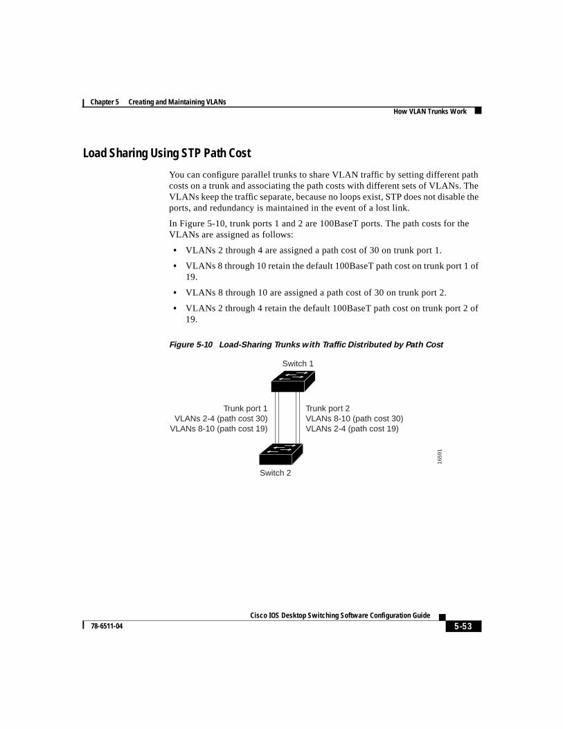
You can configure parallel trunks to share VLAN traffic by setting different pathcosts on a trunk and associating the path costs with different sets of VLANs. TheVLANs keep the traffic separate, because no loops exist, STP does not disable theports, and redundancy is maintained in the event of a lost link.
In Figure 5-10, trunk ports 1 and 2 are 100BaseT ports. The path costs for theVLANs are assigned as follows:
• VLANs 2 through 4 are assigned a path cost of 30 on trunk port 1.
• VLANs 8 through 10 retain the default 100BaseT path cost on trunk port 1 of19.
• VLANs 8 through 10 are assigned a path cost of 30 on trunk port 2.
• VLANs 2 through 4 retain the default 100BaseT path cost on trunk port 2 of19.
Figure 5-10 Load-Sharing Trunks with Traffic Distributed by Path Cost
1659
1
Switch 1
Switch 2
Trunk port 1VLANs 2-4 (path cost 30)
VLANs 8-10 (path cost 19)
Trunk port 2VLANs 8-10 (path cost 30)VLANs 2-4 (path cost 19)
Chapter 5 Creating and Maintaining VLANsHow VLAN Trunks Work
5-54Cisco IOS Desktop Switching Software Configuration Guide
78-6511-04
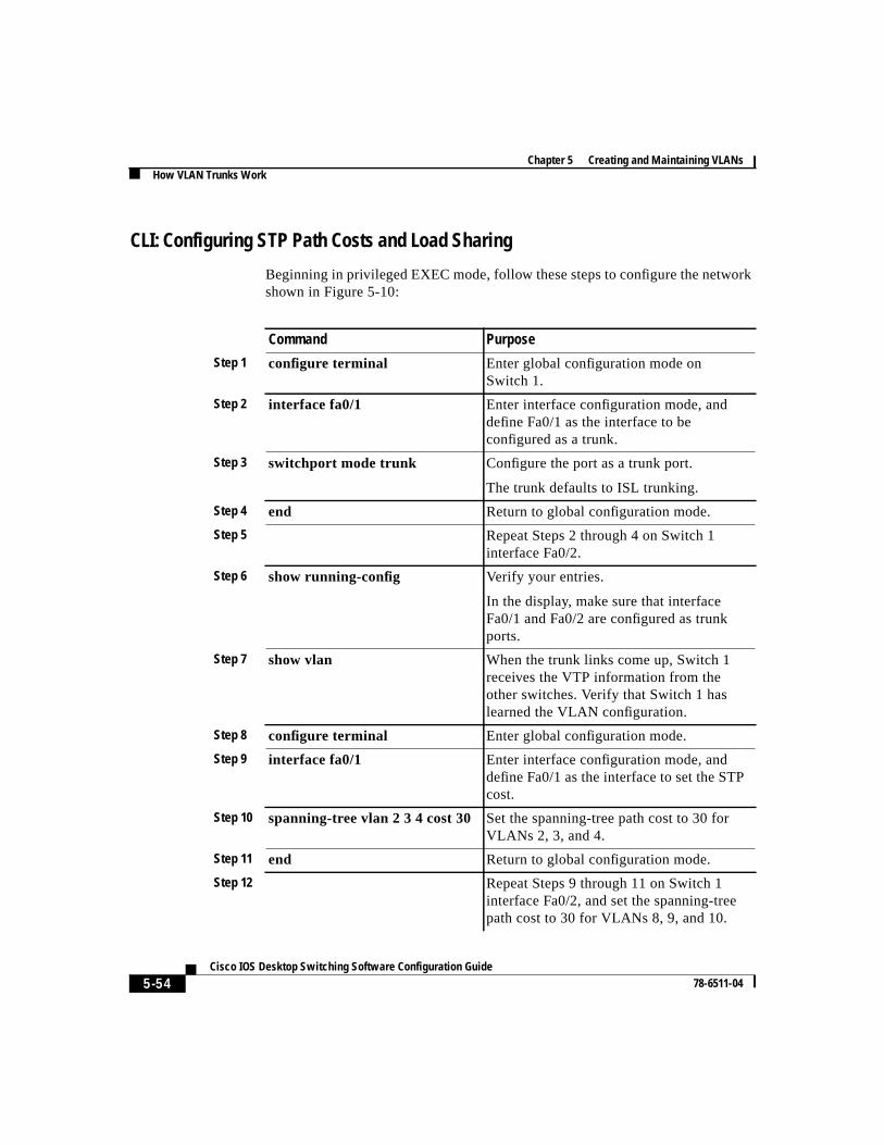
CLI: Configuring STP Path Costs and Load Sharing
Beginning in privileged EXEC mode, follow these steps to configure the networkshown in Figure 5-10:
Command Purpose
Step 1 configure terminal Enter global configuration mode onSwitch 1.
Step 2 interface fa0/1 Enter interface configuration mode, anddefine Fa0/1 as the interface to beconfigured as a trunk.
Step 3 switchport mode trunk Configure the port as a trunk port.
The trunk defaults to ISL trunking.
Step 4 end Return to global configuration mode.
Step 5 Repeat Steps 2 through 4 on Switch 1interface Fa0/2.
Step 6 show running-config Verify your entries.
In the display, make sure that interfaceFa0/1 and Fa0/2 are configured as trunkports.
Step 7 show vlan When the trunk links come up, Switch 1receives the VTP information from theother switches. Verify that Switch 1 haslearned the VLAN configuration.
Step 8 configure terminal Enter global configuration mode.
Step 9 interface fa0/1 Enter interface configuration mode, anddefine Fa0/1 as the interface to set the STPcost.
Step 10 spanning-tree vlan 2 3 4 cost 30 Set the spanning-tree path cost to 30 forVLANs 2, 3, and 4.
Step 11 end Return to global configuration mode.
Step 12 Repeat Steps 9 through 11 on Switch 1interface Fa0/2, and set the spanning-treepath cost to 30 for VLANs 8, 9, and 10.
5-55 Cisco IOS Desktop Switching Software Configuration Guide
78-6511-04
Chapter 5 Creating and Maintaining VLANsHow the VMPS Works
The “Finding More Information About IOS Commands” section on page 4-1contains the path to the complete IOS documentation.
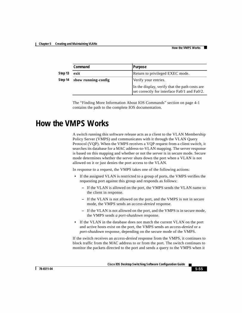
How the VMPS WorksA switch running this software release acts as a client to the VLAN MembershipPolicy Server (VMPS) and communicates with it through the VLAN QueryProtocol (VQP). When the VMPS receives a VQP request from a client switch, itsearches its database for a MAC address-to-VLAN mapping. The server responseis based on this mapping and whether or not the server is in secure mode. Securemode determines whether the server shuts down the port when a VLAN is notallowed on it or just denies the port access to the VLAN.
In response to a request, the VMPS takes one of the following actions:
• If the assigned VLAN is restricted to a group of ports, the VMPS verifies therequesting port against this group and responds as follows:
– If the VLAN is allowed on the port, the VMPS sends the VLAN name tothe client in response.
– If the VLAN is not allowed on the port, and the VMPS is not in securemode, the VMPS sends anaccess-deniedresponse.
– If the VLAN is not allowed on the port, and the VMPS is in secure mode,the VMPS sendsa port-shutdownresponse.
• If the VLAN in the database does not match the current VLAN on the portand active hosts exist on the port, the VMPS sends anaccess-denied or aport-shutdown response, depending on the secure mode of the VMPS.
If the switch receives anaccess-deniedresponse from the VMPS, it continues toblock traffic from the MAC address to or from the port. The switch continues tomonitor the packets directed to the port and sends a query to the VMPS when it
Step 13 exit Return to privileged EXEC mode.
Step 14 show running-config Verify your entries.
In the display, verify that the path costs areset correctly for interface Fa0/1 and Fa0/2.
Command Purpose
Chapter 5 Creating and Maintaining VLANsHow the VMPS Works
5-56Cisco IOS Desktop Switching Software Configuration Guide
78-6511-04
identifies a new address. If the switch receives aport-shutdownresponse from theVMPS, it disables the port. The port must be manually reenabled by using theCLI, Cluster Management software, or SNMP.
You can also use an explicit entry in the configuration table to deny access tospecific MAC addresses for security reasons. If you enter thenonekeyword forthe VLAN name, the VMPS sends anaccess-denied or port-shutdown response.
Dynamic Port VLAN MembershipA dynamic (nontrunking) port on the switch can belong to only one VLAN. Whenthe link comes up, the switch does not forward traffic to or from this port until theVMPS provides the VLAN assignment. The VMPS receives the source MACaddress from the first packet of a new host connected to the dynamic port andattempts to match the MAC address to a VLAN in the VMPS database.
If there is a match, the VMPS sends the VLAN number for that port. If the clientswitch was not previously configured, it uses the domain name from the first VTPpacket it receives on its trunk port from the VMPS. If the client switch waspreviously configured, it includes its domain name in the query packet to theVMPS to obtain its VLAN number. The VMPS verifies that the domain name inthe packet matches its own domain name before accepting the request andresponds to the client with the assigned VLAN number for the client.
If there is no match, the VMPS either denies the request or shuts down the port(depending on the VMPS secure mode setting). For more information on possibleVMPS responses, see the “How the VMPS Works” section on page 5-55.
Multiple hosts (MAC addresses) can be active on a dynamic port if they are all inthe same VLAN; however, the VMPS shuts down a dynamic port if more than 20hosts are active on the port.
If the link goes down on a dynamic port, the port returns to an isolated state anddoes not belong to a VLAN. Any hosts that come online through the port arechecked again with the VMPS before the port is assigned to a VLAN.
5-57 Cisco IOS Desktop Switching Software Configuration Guide
78-6511-04
Chapter 5 Creating and Maintaining VLANsHow the VMPS Works
VMPS Database Configuration FileThe VMPS contains a database configuration file that you create. This ASCII textfile is stored on a switch-accessible TFTP server that functions as a VMPS server.The file contains VMPS information, such as the domain name, the fall-backVLAN name, and the MAC address-to-VLAN mapping. A 2900 or 3500 XLswitch running this software release cannot act as the VMPS. Use aCatalyst 5000 series switch as the VMPS.
The VMPS database configuration file on the server must use the 2900 XL and3500 XL convention for naming ports. For example, Fa0/5 is fixed-port number 5.
If the switch is a cluster member, the command switch adds the name of the switchbefore the Fa. For example, es3%Fa02 refers to fixed 10/100 port 2 on memberswitch 3. These naming conventions must be used in the VMPS databaseconfiguration file when it is configured to support a cluster.
You can configure a fallback VLAN name. If you connect a device with a MACaddress that is not in the database, the VMPS sends the fallback VLAN name tothe client. If you do not configure a fallback VLAN and the MAC address doesnot exist in the database, the VMPS sends anaccess-denied response. If theVMPS is in secure mode, it sends aport-shutdown response.
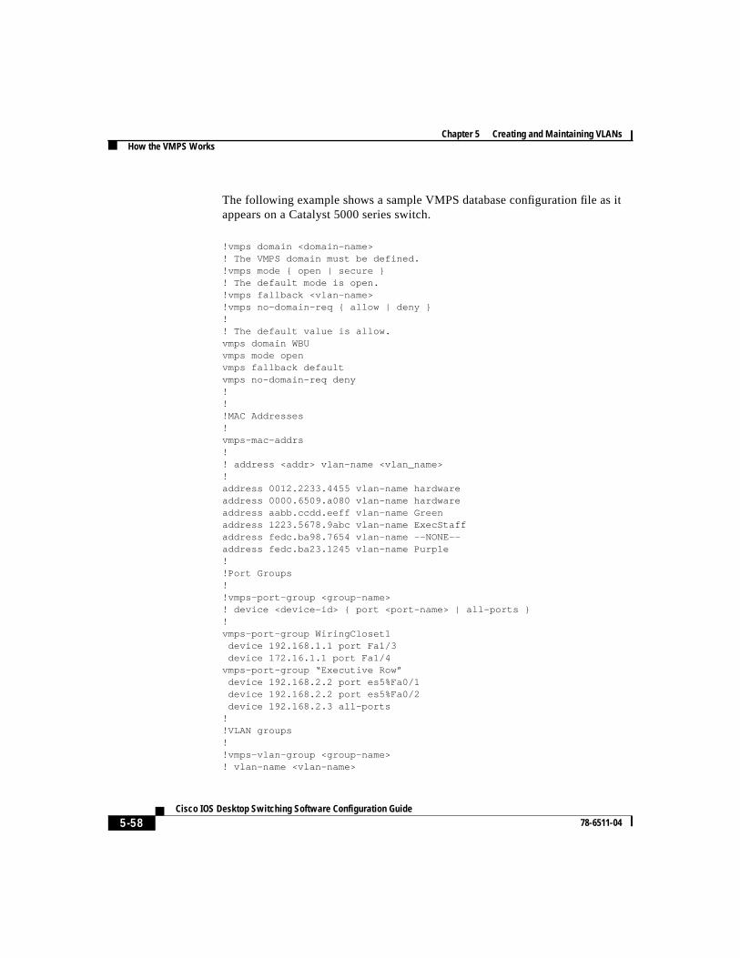
Chapter 5 Creating and Maintaining VLANsHow the VMPS Works
5-58Cisco IOS Desktop Switching Software Configuration Guide
78-6511-04
The following example shows a sample VMPS database configuration file as itappears on a Catalyst 5000 series switch.
!vmps domain <domain-name>! The VMPS domain must be defined.!vmps mode { open | secure }! The default mode is open.!vmps fallback <vlan-name>!vmps no-domain-req { allow | deny }!! The default value is allow.vmps domain WBUvmps mode openvmps fallback defaultvmps no-domain-req deny!!!MAC Addresses!vmps-mac-addrs!! address <addr> vlan-name <vlan_name>!address 0012.2233.4455 vlan-name hardwareaddress 0000.6509.a080 vlan-name hardwareaddress aabb.ccdd.eeff vlan-name Greenaddress 1223.5678.9abc vlan-name ExecStaffaddress fedc.ba98.7654 vlan-name --NONE--address fedc.ba23.1245 vlan-name Purple!!Port Groups!!vmps-port-group <group-name>! device <device-id> { port <port-name> | all-ports }!vmps-port-group WiringCloset1 device 192.168.1.1 port Fa1/3 device 172.16.1.1 port Fa1/4vmps-port-group “Executive Row” device 192.168.2.2 port es5%Fa0/1 device 192.168.2.2 port es5%Fa0/2 device 192.168.2.3 all-ports!!VLAN groups!!vmps-vlan-group <group-name>! vlan-name <vlan-name>
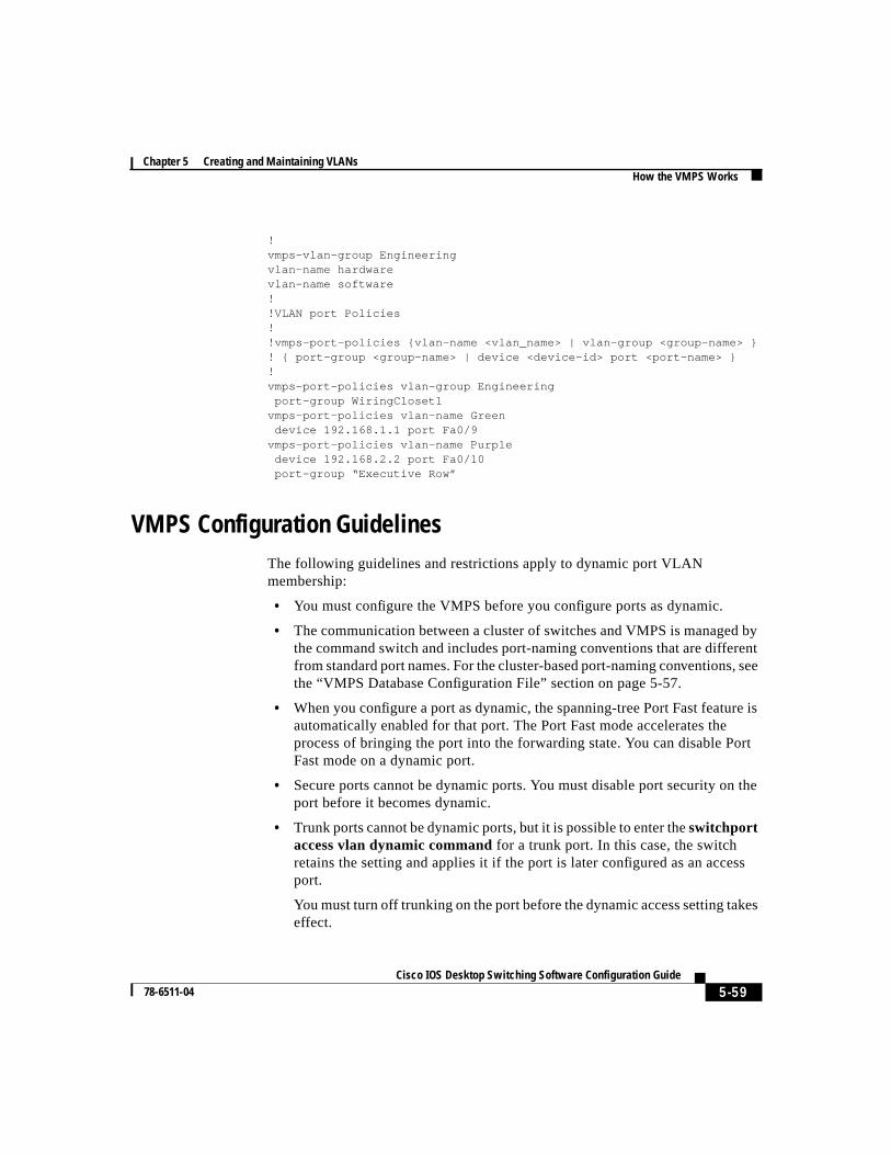
5-59 Cisco IOS Desktop Switching Software Configuration Guide
78-6511-04
Chapter 5 Creating and Maintaining VLANsHow the VMPS Works
!vmps-vlan-group Engineeringvlan-name hardwarevlan-name software!!VLAN port Policies!!vmps-port-policies {vlan-name <vlan_name> | vlan-group <group-name> }! { port-group <group-name> | device <device-id> port <port-name> }!vmps-port-policies vlan-group Engineering port-group WiringCloset1vmps-port-policies vlan-name Green device 192.168.1.1 port Fa0/9vmps-port-policies vlan-name Purple device 192.168.2.2 port Fa0/10 port-group “Executive Row”
VMPS Configuration GuidelinesThe following guidelines and restrictions apply to dynamic port VLANmembership:
• You must configure the VMPS before you configure ports as dynamic.
• The communication between a cluster of switches and VMPS is managed bythe command switch and includes port-naming conventions that are differentfrom standard port names. For the cluster-based port-naming conventions, seethe “VMPS Database Configuration File” section on page 5-57.
• When you configure a port as dynamic, the spanning-tree Port Fast feature isautomatically enabled for that port. The Port Fast mode accelerates theprocess of bringing the port into the forwarding state. You can disable PortFast mode on a dynamic port.
• Secure ports cannot be dynamic ports. You must disable port security on theport before it becomes dynamic.
• Trunk ports cannot be dynamic ports, but it is possible to enter theswitchportaccess vlan dynamic command for a trunk port. In this case, the switchretains the setting and applies it if the port is later configured as an accessport.
You must turn off trunking on the port before the dynamic access setting takeseffect.
Chapter 5 Creating and Maintaining VLANsHow the VMPS Works
5-60Cisco IOS Desktop Switching Software Configuration Guide
78-6511-04
• Dynamic ports cannot be network ports or monitor ports.
• The VTP management domain of the VMPS client and the VMPS server mustbe the same.
Default VMPS ConfigurationTable 5-13 shows the default VMPS and dynamic port configuration on clientswitches.
Configuring Dynamic VLAN MembershipYou configure dynamic VLANs by using the VMPS Server (Figure 5-11) and theVMPS Info (Figure 5-12) tabs of the VMPS Configuration window.
To display this window, selectCluster>VMPS Configuration from the menu bar,and click theVMPS Server or theVMPS Info tab.
Table 5-13 Default VMPS Client and Dynamic Port Configuration
Feature Default Configuration
VMPS domain server None
VMPS reconfirminterval
60 minutes
VMPS server retrycount
3
Dynamic ports None configured
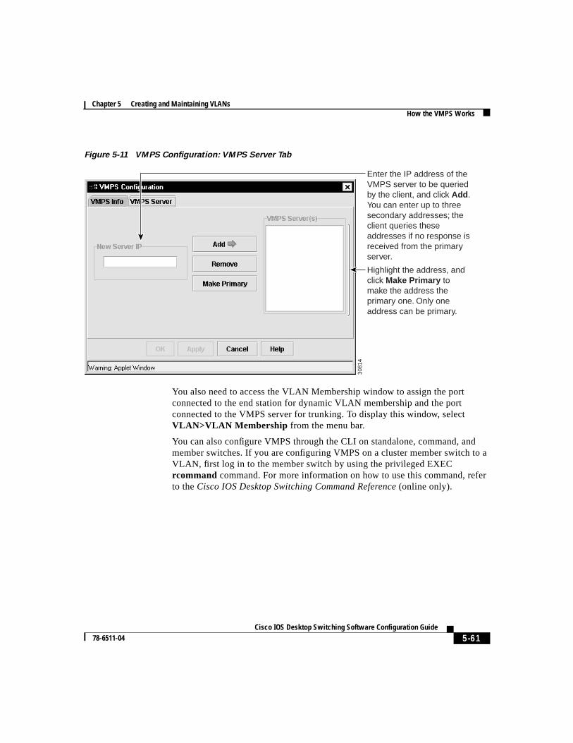
5-61 Cisco IOS Desktop Switching Software Configuration Guide
78-6511-04
Chapter 5 Creating and Maintaining VLANsHow the VMPS Works
Figure 5-11 VMPS Configuration: VMPS Server Tab
You also need to access the VLAN Membership window to assign the portconnected to the end station for dynamic VLAN membership and the portconnected to the VMPS server for trunking. To display this window, selectVLAN>VLAN Membership from the menu bar.
You can also configure VMPS through the CLI on standalone, command, andmember switches. If you are configuring VMPS on a cluster member switch to aVLAN, first log in to the member switch by using the privileged EXECrcommand command. For more information on how to use this command, referto theCisco IOS Desktop Switching Command Reference (online only).
Enter the IP address of the VMPS server to be queried by the client, and click Add . You can enter up to three secondary addresses; the client queries these addresses if no response is received from the primary server.
Highlight the address, and click Make Primary to make the address the primary one. Only one address can be primary.
3081
4
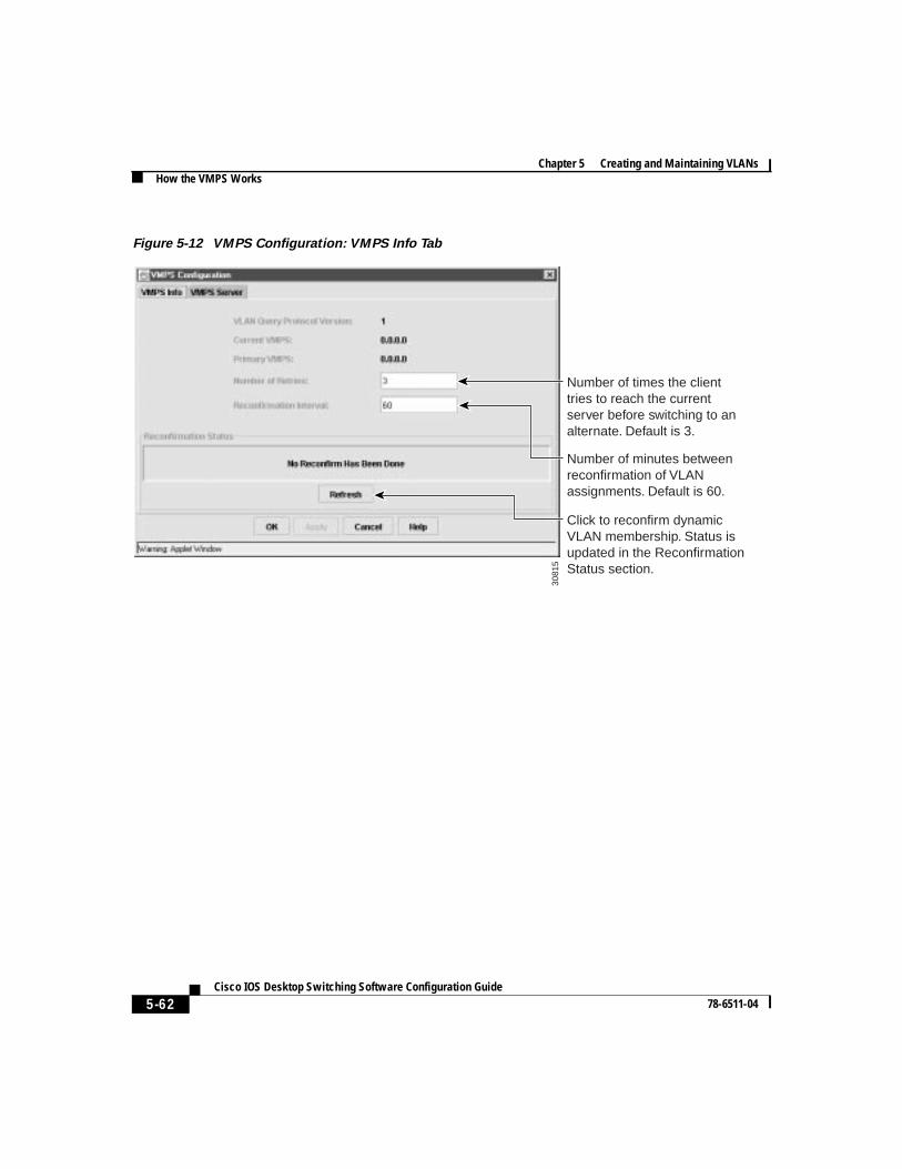
Chapter 5 Creating and Maintaining VLANsHow the VMPS Works
5-62Cisco IOS Desktop Switching Software Configuration Guide
78-6511-04
Figure 5-12 VMPS Configuration: VMPS Info Tab
3081
5
Number of times the client tries to reach the current server before switching to an alternate. Default is 3.
Number of minutes between reconfirmation of VLAN assignments. Default is 60.
Click to reconfirm dynamic VLAN membership. Status is updated in the Reconfirmation Status section.
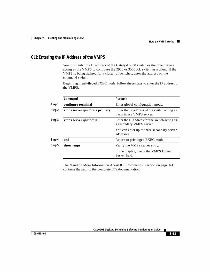
5-63 Cisco IOS Desktop Switching Software Configuration Guide
78-6511-04
Chapter 5 Creating and Maintaining VLANsHow the VMPS Works
CLI: Entering the IP Address of the VMPS
You must enter the IP address of the Catalyst 5000 switch or the other deviceacting as the VMPS to configure the 2900 or 3500 XL switch as a client. If theVMPS is being defined for a cluster of switches, enter the address on thecommand switch.
Beginning in privileged EXEC mode, follow these steps to enter the IP address ofthe VMPS:
The “Finding More Information About IOS Commands” section on page 4-1contains the path to the complete IOS documentation.
Command Purpose
Step 1 configure terminal Enter global configuration mode.
Step 2 vmps serveripaddressprimary Enter the IP address of the switch acting asthe primary VMPS server.
Step 3 vmps serveripaddress Enter the IP address for the switch acting asa secondary VMPS server.
You can enter up to three secondary serveraddresses.
Step 4 end Return to privileged EXEC mode.
Step 5 show vmps Verify the VMPS server entry.
In the display, check the VMPS DomainServer field.
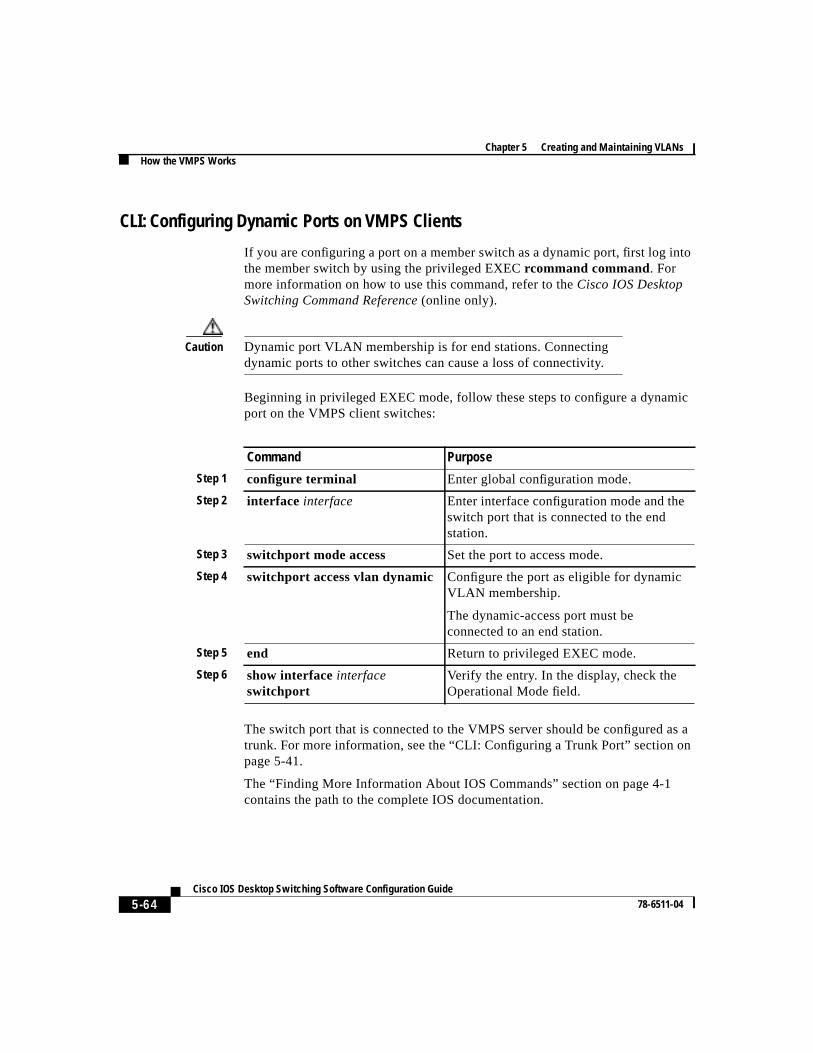
Chapter 5 Creating and Maintaining VLANsHow the VMPS Works
5-64Cisco IOS Desktop Switching Software Configuration Guide
78-6511-04
CLI: Configuring Dynamic Ports on VMPS Clients
If you are configuring a port on a member switch as a dynamic port, first log intothe member switch by using the privileged EXECrcommand command. Formore information on how to use this command, refer to theCisco IOS DesktopSwitching Command Reference (online only).
Caution Dynamic port VLAN membership is for end stations. Connectingdynamic ports to other switches can cause a loss of connectivity.
Beginning in privileged EXEC mode, follow these steps to configure a dynamicport on the VMPS client switches:
The switch port that is connected to the VMPS server should be configured as atrunk. For more information, see the “CLI: Configuring a Trunk Port” section onpage 5-41.
The “Finding More Information About IOS Commands” section on page 4-1contains the path to the complete IOS documentation.
Command Purpose
Step 1 configure terminal Enter global configuration mode.
Step 2 interface interface Enter interface configuration mode and theswitch port that is connected to the endstation.
Step 3 switchport mode access Set the port to access mode.
Step 4 switchport access vlan dynamic Configure the port as eligible for dynamicVLAN membership.
The dynamic-access port must beconnected to an end station.
Step 5 end Return to privileged EXEC mode.
Step 6 show interfaceinterfaceswitchport
Verify the entry. In the display, check theOperational Mode field.
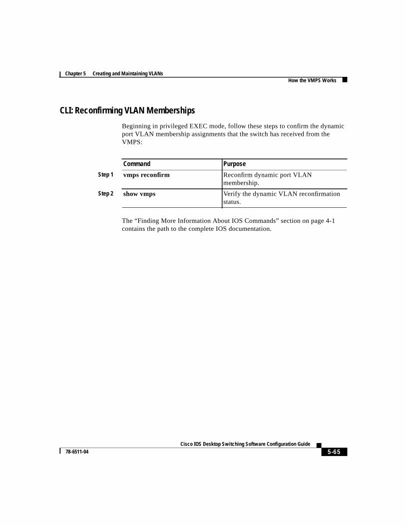
5-65 Cisco IOS Desktop Switching Software Configuration Guide
78-6511-04
Chapter 5 Creating and Maintaining VLANsHow the VMPS Works
CLI: Reconfirming VLAN Memberships
Beginning in privileged EXEC mode, follow these steps to confirm the dynamicport VLAN membership assignments that the switch has received from theVMPS:
The “Finding More Information About IOS Commands” section on page 4-1contains the path to the complete IOS documentation.
Command Purpose
Step 1 vmps reconfirm Reconfirm dynamic port VLANmembership.
Step 2 show vmps Verify the dynamic VLAN reconfirmationstatus.
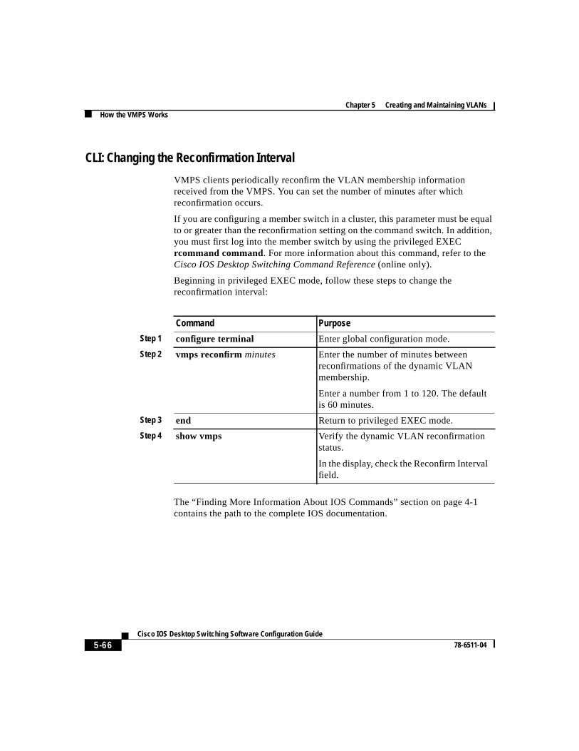
Chapter 5 Creating and Maintaining VLANsHow the VMPS Works
5-66Cisco IOS Desktop Switching Software Configuration Guide
78-6511-04
CLI: Changing the Reconfirmation Interval
VMPS clients periodically reconfirm the VLAN membership informationreceived from the VMPS. You can set the number of minutes after whichreconfirmation occurs.
If you are configuring a member switch in a cluster, this parameter must be equalto or greater than the reconfirmation setting on the command switch. In addition,you must first log into the member switch by using the privileged EXECrcommand command. For more information about this command, refer to theCisco IOS Desktop Switching Command Reference (online only).
Beginning in privileged EXEC mode, follow these steps to change thereconfirmation interval:
The “Finding More Information About IOS Commands” section on page 4-1contains the path to the complete IOS documentation.
Command Purpose
Step 1 configure terminal Enter global configuration mode.
Step 2 vmps reconfirm minutes Enter the number of minutes betweenreconfirmations of the dynamic VLANmembership.
Enter a number from 1 to 120. The defaultis 60 minutes.
Step 3 end Return to privileged EXEC mode.
Step 4 show vmps Verify the dynamic VLAN reconfirmationstatus.
In the display, check the Reconfirm Intervalfield.
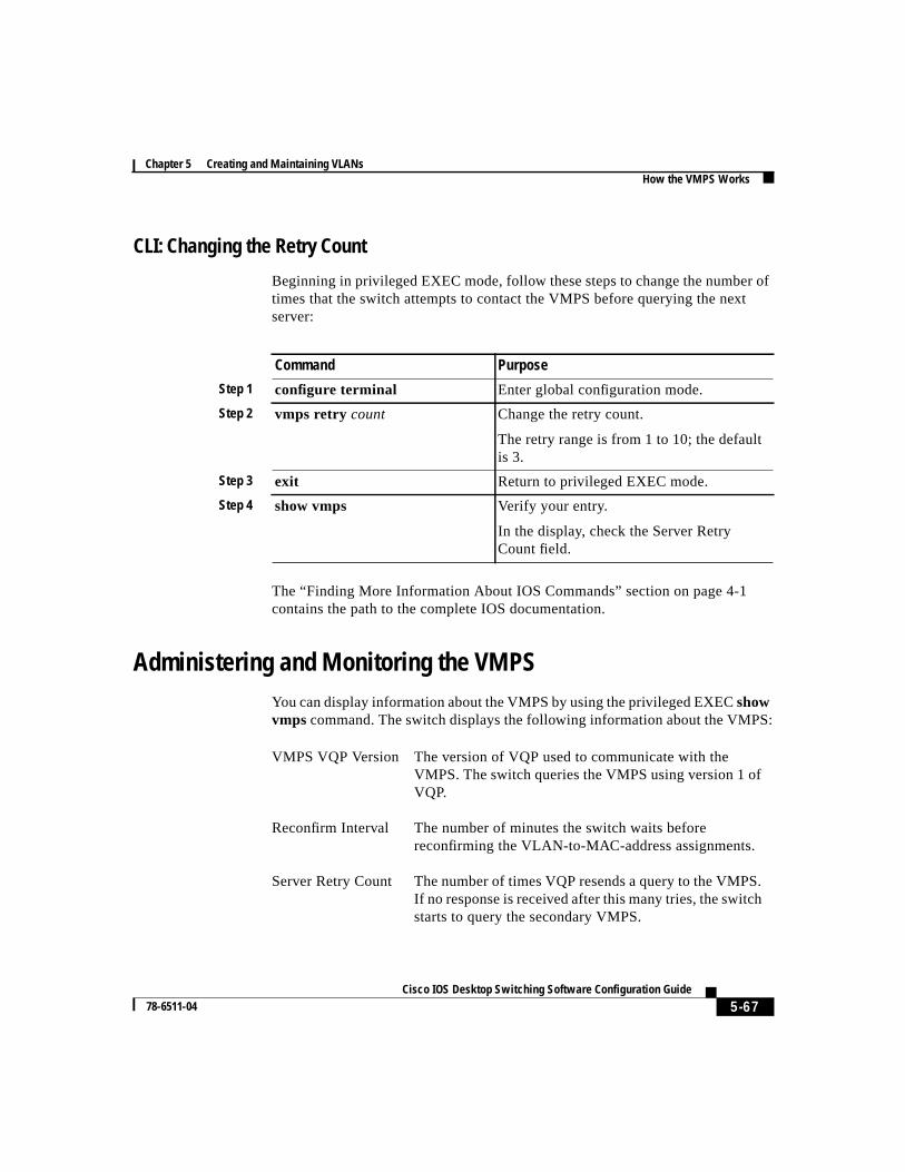
5-67 Cisco IOS Desktop Switching Software Configuration Guide
78-6511-04
Chapter 5 Creating and Maintaining VLANsHow the VMPS Works
CLI: Changing the Retry Count
Beginning in privileged EXEC mode, follow these steps to change the number oftimes that the switch attempts to contact the VMPS before querying the nextserver:
The “Finding More Information About IOS Commands” section on page 4-1contains the path to the complete IOS documentation.
Administering and Monitoring the VMPSYou can display information about the VMPS by using the privileged EXECshowvmps command. The switch displays the following information about the VMPS:
Command Purpose
Step 1 configure terminal Enter global configuration mode.
Step 2 vmps retry count Change the retry count.
The retry range is from 1 to 10; the defaultis 3.
Step 3 exit Return to privileged EXEC mode.
Step 4 show vmps Verify your entry.
In the display, check the Server RetryCount field.
VMPS VQP Version The version of VQP used to communicate with theVMPS. The switch queries the VMPS using version 1 ofVQP.
Reconfirm Interval The number of minutes the switch waits beforereconfirming the VLAN-to-MAC-address assignments.
Server Retry Count The number of times VQP resends a query to the VMPS.If no response is received after this many tries, the switchstarts to query the secondary VMPS.
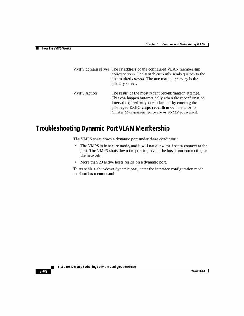
Chapter 5 Creating and Maintaining VLANsHow the VMPS Works
5-68Cisco IOS Desktop Switching Software Configuration Guide
78-6511-04
Troubleshooting Dynamic Port VLAN MembershipThe VMPS shuts down a dynamic port under these conditions:
• The VMPS is in secure mode, and it will not allow the host to connect to theport. The VMPS shuts down the port to prevent the host from connecting tothe network.
• More than 20 active hosts reside on a dynamic port.
To reenable a shut-down dynamic port, enter the interface configuration modeno shutdown command.
VMPS domain server The IP address of the configured VLAN membershippolicy servers. The switch currently sends queries to theone markedcurrent. The one markedprimary is theprimary server.
VMPS Action The result of the most recent reconfirmation attempt.This can happen automatically when the reconfirmationinterval expired, or you can force it by entering theprivileged EXECvmps reconfirm command or itsCluster Management software or SNMP equivalent.
5-69 Cisco IOS Desktop Switching Software Configuration Guide
78-6511-04
Chapter 5 Creating and Maintaining VLANsHow the VMPS Works
Dynamic Port VLAN Membership Configuration ExampleFigure 5-13 shows a network with a VMPS server switch and VMPS clientswitches with dynamic ports. In this example, these assumptions apply:
• The VMPS server and the VMPS client are separate switches.
• The Catalyst 5000 series Switch 1 is the primary VMPS server.
• The Catalyst 5000 series Switch 3 and Switch 10 are secondary VMPSservers.
• End stations are connected to these clients:
– Catalyst 2900 XL Switch 2
– Catalyst 3500 XL Switch 9
• The database configuration file is called Bldg-G.db and is stored on the TFTPserver with the IP address 172.20.22.7.
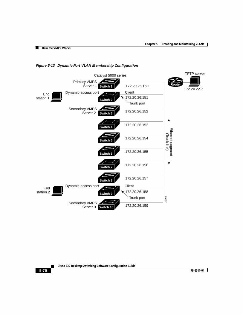
Chapter 5 Creating and Maintaining VLANsHow the VMPS Works
5-70Cisco IOS Desktop Switching Software Configuration Guide
78-6511-04
Figure 5-13 Dynamic Port VLAN Membership Configuration
Primary VMPSServer 1
Secondary VMPSServer 2
Secondary VMPSServer 3
172.20.26.150
172.20.26.151
Trunk port
Catalyst 5000 series
172.20.26.152
Ethernet segm
ent(Trunk link)
172.20.26.153
172.20.26.154
172.20.26.155
172.20.26.156
172.20.26.157
172.20.26.158
172.20.26.159
Client
Client
Endstation 2
Endstation 1
TFTP server
Dynamic-access port
Dynamic-access port
Switch 10
Switch 9
Switch 8
Switch 7
Switch 6
Switch 5
Switch 3
Switch 2
Switch 1
Switch 4
172.20.22.7
3076
9Trunk port
Router