control joints for concrete masonry walls— tek 10 …
TRANSCRIPT

A n i n f o r m a t i o n s e r i e s f r o m t h e n a t i o n a l a u t h o r i t y o n c o n c r e t e m a s o n r y t e c h n o l o g y
NCMA TEK 10-2C 1
CONTROL JOINTS FORCONCRETE MASONRY WALLS—EMPIRICAL METHOD
INTRODUCTION
Concrete masonry is a popular construction material because its inherent attributes satisfy the diverse needs of both exterior and interior walls. While these attributes are the primary basis for concrete masonry’s popularity, performance should not be taken for granted. Like all construction systems, design decisions significantly influence field performance of the concrete masonry wall system. Proper application of crack control measures, including control joints when required, can help ensure satisfactory performance of the concrete masonry. Note that crack control considerations for concrete ma-sonry veneers differ from the guidance presented below. The
Related TEK:7-1C, 10-1A, 10-3, 10-4
Keywords: bond beams, construction details, control joints, crack control, joint reinforcement, reinforcing bars, reinforced concrete masonry, shrinkage, wall movement
TEK 10-2CMovement Control (2010)
Figure 1—Typical Control Joint Locations
At maximum ofone-half controljoint spacingfrom corners
Between main andintersecting wall
At changes in wall height
At pilasters andchanges in wallthickness
Adjacent to lintel and through opening if not crossing vertical reinforcement
reader is referred to TEK 10-4, Crack Control for Concrete Brick and Other Concrete Masonry Veneers (ref. 3), for more detailed information. Control joints are one method used to relieve horizontal tensile stresses due to shrinkage of the concrete masonry units, mortar, and when used, grout. They are essentially vertical planes of weakness built into the wall to reduce restraint and permit longitudinal movement due to anticipated shrinkage, and are located where stress concentrations may occur. A bond break is accomplished by replacing all or part of a vertical mortar joint with a backer rod and sealant. This keeps the joint weather tight while accommodating small movements. Joint reinforcement and other horizontal reinforcement should be

2 NCMA TEK 10-2C
discontinued at control joints unless it is required for structural purposes, as it will act to restrain horizontal movement. When control joints are required, concrete masonry only requires vertical control joints. When materials with differ-ent movement properties, such as concrete masonry and clay masonry, are used in the same wythe the movement differ-ence needs to be accounted for in the design. Normally, joint reinforcement is used in the common joint between the two to distribute the forces and keep any cracks that form tightly closed. Another option is to provide a horizontal slip plane between the two materials to accommodate the differential movement. See Clay and Concrete Masonry Banding Details, TEK 5-2A (ref. 1), for more detailed information. Control joints are typically required in exposed above grade concrete masonry walls, where shrinkage cracking may detract from the appearance of the wall, and to limit moisture or air infiltration. Shrinkage cracks in concrete masonry are not a structural concern. In addition, walls with adequate horizontal reinforcement may not require control joints, as the reinforcement effectively reduces the width of shrinkage cracks. See TEK 10-3, Control Joints for Concrete Masonry Walls—Alternative Engineered Method (ref. 2), for more in-formation. Foundation walls traditionally do not include control joints due to concerns with waterproofing the joint to withstand hydrostatic pressure. Additionally, since foundation walls are subjected to relatively constant temperature and moisture conditions, shrinkage cracking in below grade walls tends to be less significant than in above grade walls. This TEK focuses on cracking resulting from internal volume change of the concrete masonry. Potential cracking resulting from externally applied design loads due to wind, soil pressure, seismic forces, or differential settlement of founda-tions is controlled by structural design considerations not ad-dressed here. Where external loads are an issue in combination with internal volume change, the design should consider the combined effects of these influences on cracking.
CONTROL JOINT PLACEMENT
When required, control joints should be located where volume changes in the masonry due to drying shrinkage, carbonation, or temperature changes are likely to create ten-sion in the masonry that will exceed its tensile capacity. In practice, this can be difficult to determine, but several methods are presented in the following sections to provide guidance in locating control joints. In addition, care should be taken to provide joints at loca-tions of stress concentrations such as (see Figure 1):1. at changes in wall height,2. at changes in wall thickness, such as at pipe and duct chases
and pilasters,3. at (above) movement joints in foundations and floors,4. at (above and below) movement joints in roofs and floors
that bear on a wall,5. near one or both sides of door and window openings, (see
following subsection, Control Joints at Openings), and6. adjacent to corners of walls or intersections within a distance
equal to half the control joint spacing.
Consideration must also be given to the effect of control joint placement on load distribution within the wall. For example, locating control joints at the ends of lintels may compromise arching action. Therefore, it may be prudent to design the lintel to carry the full weight of the wall above it in addition to any superimposed loads.
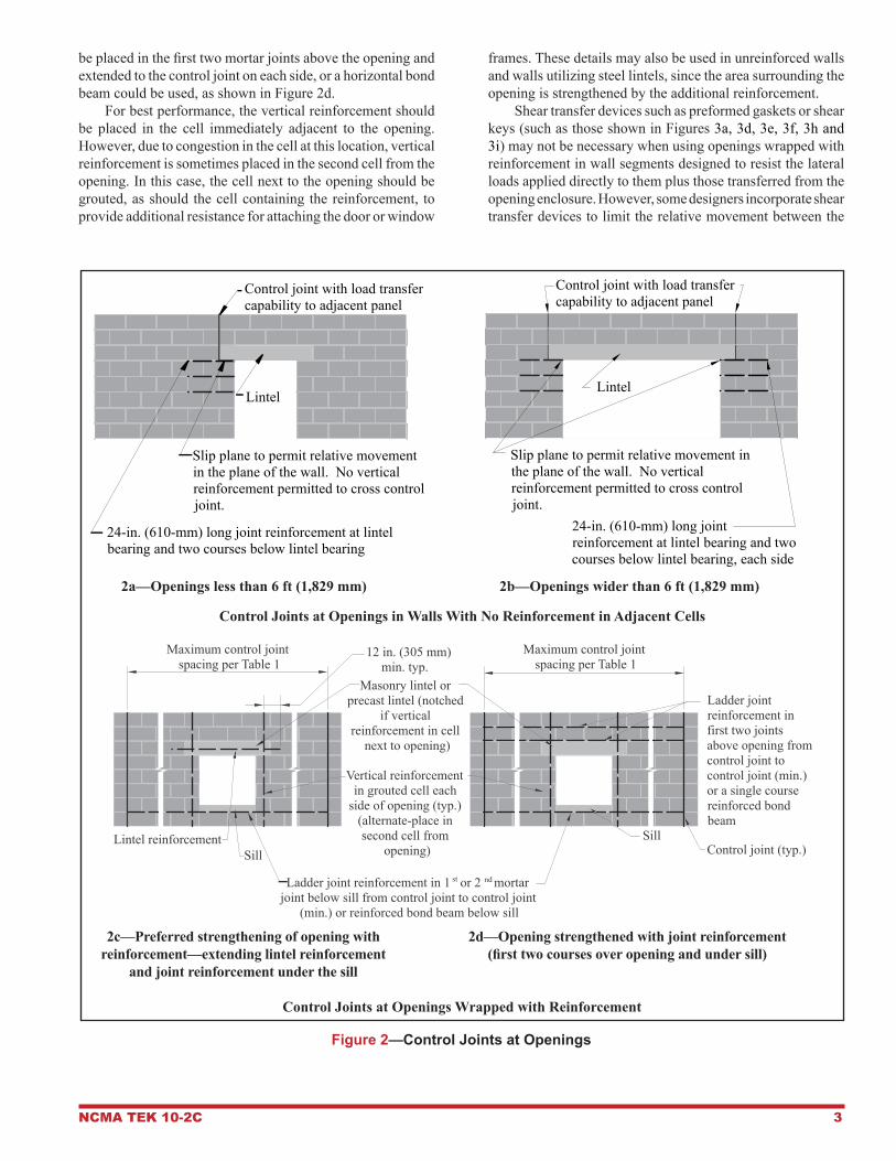
Control Joints at Openings Because cracking occurs in the planes of greatest weak-ness, openings are particularly vulnerable. For an opening of up to 6 ft (1.83 m) in width that are not wrapped with reinforcement, a control joint should be placed at one side of the opening as shown in Figure 2a. Notice that the joint goes around the lintel and allowance for movement (a slip plane in the form of flashing or other bond breaker) between the lintel and the masonry must be provided. Because the lintel is not laterally supported at the bottom due to the slip plane, control joints capable of providing load transfer between panels are required, such as the joints shown in Figures 3a, 3d, 3e, 3f, 3h and 3i. In Figure 2a, continuous vertical reinforcement cannot be provided in the cell adjacent to the opening on the left, as crossing the horizontal portion of the control joint (i.e., the slip plane) would effectively pin the two sections together, restraining relative movement. To resist the lateral movement around the slip plane, 24-in. (610-mm) long horizontal joint reinforcement may be placed at the lintel bearing location and two courses below. If utilizing concrete masonry veneered steel beams over openings in lieu of concrete masonry or precast lintels, it is critical that the steel beam not be welded to the bearing plate(s) where designated control joints are to be constructed, as this will pin the two sections together, restraining movement. When a slip plane under the bond beam is used for open-ings larger than 6 ft (1.83 m), control joints are recommended on both sides of the opening as shown in Figure 2b. Again, the control joint goes under and up the side of the lintel, and allowance for movement between the lintel and the masonry must be provided. Because there is no lateral support at the bottom of the lintel, provision must also be made for load transfer between the panels. An alternative to avoid having the vertical reinforcement cross the slip plane is to place the reinforcement in the next cell over. Another alternative is to place the control joint away from the opening if adequate tensile reinforcement is placed above, below and beside the opening as discussed below. In walls containing vertical reinforcement, the cell adjacent to the opening is usually grouted and reinforced to provide solid support and additional strength for jambs. Using the same type of detail as for the unreinforced wall would require the control joint to cross the vertical reinforcement, thereby preventing movement and defeating the purpose of the control joint. However, if the opening is completely sur-rounded by reinforcement as shown in Figure 2c and 2d, the area around the opening is strengthened and control joints can be placed away from the opening. As an alternative to extending the lintel reinforcement a minimum of 12 in. (305 mm) past the vertical reinforcement adjacent to the opening (Figure 2c), joint reinforcement may
NCMA TEK 10-2C 3
be placed in the first two mortar joints above the opening and extended to the control joint on each side, or a horizontal bond beam could be used, as shown in Figure 2d. For best performance, the vertical reinforcement should be placed in the cell immediately adjacent to the opening. However, due to congestion in the cell at this location, vertical reinforcement is sometimes placed in the second cell from the opening. In this case, the cell next to the opening should be grouted, as should the cell containing the reinforcement, to provide additional resistance for attaching the door or window
frames. These details may also be used in unreinforced walls and walls utilizing steel lintels, since the area surrounding the opening is strengthened by the additional reinforcement. Shear transfer devices such as preformed gaskets or shear keys (such as those shown in Figures 3a, 3d, 3e, 3f, 3h and 3i) may not be necessary when using openings wrapped with reinforcement in wall segments designed to resist the lateral loads applied directly to them plus those transferred from the opening enclosure. However, some designers incorporate shear transfer devices to limit the relative movement between the
Figure 2—Control Joints at Openings
2c—Preferred strengthening of opening with 2d—Opening strengthened with joint reinforcement reinforcement—extendinglintelreinforcement (firsttwocoursesoveropeningandundersill) andjointreinforcementunderthesill
ControlJointsatOpeningsWrappedwithReinforcement
2a—Openingslessthan6ft(1,829mm) 2b—Openingswiderthan6ft(1,829mm)
ControlJointsatOpeningsinWallsWithNoReinforcementinAdjacentCells
Control joint with load transfer capability to adjacent panel
Slip plane to permit relative movement in the plane of the wall. No vertical reinforcement permitted to cross control joint.
Lintel
24-in. (610-mm) long joint reinforcement at lintel bearing and two courses below lintel bearing
Control joint with load transfer capability to adjacent panel
Slip plane to permit relative movement in the plane of the wall. No vertical reinforcement permitted to cross control joint.
24-in. (610-mm) long joint reinforcement at lintel bearing and two courses below lintel bearing, each side
Lintel
Vertical reinforcement in grouted cell each
side of opening (typ.) (alternate-place in second cell from
opening)
Ladder joint reinforcement in 1 or 2 mortar joint below sill from control joint to control joint
(min.) or reinforced bond beam below sill
Masonry lintel or precast lintel (notched
if vertical reinforcement in cell
next to opening)
Ladder joint reinforcement in first two joints above opening from control joint to control joint (min.) or a single course reinforced bond beam
Control joint (typ.)Sill
Sill
Maximum control joint spacing per Table 1
Lintel reinforcement
12 in. (305 mm) min. typ.
Maximum control joint spacing per Table 1
st nd

4 NCMA TEK 10-2C
two panels on either side of a control joint, thereby reducing the stress on the joint sealant and providing longer life.
EMPIRICAL CRACK CONTROL CRITERIA
At other points of wall stress concentration, control joints are used to effectively divide a wall into a series of isolated panels. Table 1 lists recommended maximum spacing of these control joints based on empirical criteria. This criteria has been developed based on successful historical performance over many years in various geographical conditions. The empirical method is the most commonly used method of locating control joints and is applicable to most building types. An engineered method is presented in TEK 10-3 Control Joints for Concrete Masonry Walls—Alternative Engineered
Method, which is based on limiting crack width to 0.02 in. (0.51 mm), since water repellent coatings can effectively resist water penetration for cracks of this size. The engineered method is generally used only when unusual conditions are encountered such as dark-colored units in climates with large temperature changes. The provisions in this TEK assume that units used in the construction comply with the minimum requirements of ASTM C90, Standard Specification for Loadbearing Concrete Masonry Units (ref. 4) and that a minimum amount of horizontal reinforcement is provided between control joints as indicated in Footnote 1 of Table 1. The minimum area of reinforce-ment given, 0.025 in.2/ft (52.9 mm2/m) of height, translates to horizontal reinforcement spaced as indicated in Table 2. It is intended to provide the most straightforward guidelines for those cases where detailed volume change properties of the concrete masonry are not known at the time of design. As indicated in Table 1 Footnote 3, local experience may justify an adjustment to the control joint spacings presented in the table. To illustrate these criteria, consider a 20 ft (6.10 m) tall warehouse with walls 100 ft (30.48 m) long. Table 1 indicates a maximum control joint spacing of the lesser of:• a length to height ratio of 1½ : 1, which corresponds to 1½
x (20 ft) = 30 ft (9.14 m), or• control joints spaced every 25 ft (7.62 m). In this example, the maximum spacing of 25 ft (7.62 m) governs over the length to height ratio. For walls containing masonry parapets, consider the para-pet as part of the masonry wall below when determining the length to height ratio if it is structurally connected by masonry materials.
CONSTRUCTION
Common control joint details are illustrated in Figure 3. The joints permit free longitudinal movement, and some also allow the transfer of lateral or out-of-plane shear loads. Although the details in Figure 3 show vertical reinforcement on each side of the control joint, walls that do not otherwise require vertical reinforcement will not require reinforcement at the control joints. Out-of-plane shear loads can be transferred by provid-ing a shear key, as shown in Figures 3a, 3d, 3e, 3f, 3h and 3i. Figures 3f and 3i show smooth dowel bars placed across the control joint to transfer shear. The dowels are typically greased or placed in a plastic sleeve to prevent bond and allow unrestrained longitudinal movement. Figure 3h is a variation on this approach, where one horizontal bond beam reinforcing bar extends across the control joint, and is similarly debonded to allow longitudinal movement. Control joints can also be constructed using sash units, which accommodate the shear key of a preformed control joint gasket, as shown in Figure 3a. The gaskets are gener-ally available in either PVC, complying with ASTM D2287, Standard Specification for Nonrigid Vinyl Chloride Polymer and Copolymer Molding and Extrusion Compounds (ref. 7), or rubber compounds complying with ASTM D2000, Standard Classification System for Rubber Products in Automotive
Table 1—Recommended Control Joint Spacing for Above Grade Exposed
Concrete Masonry WallsA
Distancebetweenjointsnottoexceedthelesserof:Lengthtoheightratioorft(m)
1½ : 1 25 (7.62)A Notes:1. Table values are based on the use of horizontal
reinforcement having an equivalent area of not less than 0.025 in.2/ft (52.9 mm2/m) of height to keep unplanned cracks closed (see Table 2).
2. Criteria applies to all concrete masonry units.3. This criteria is based on experience over a wide
geographical area. Control joint spacing should be adjusted up or down where local experience justi-fies. For example, in high seismic regions where a substantial amount of horizontal reinforcement is provided, spacing of control joints can be increased and possibly even eliminated. See TEK 10-3 (ref. 2) for further information.
Table 2—Maximum Spacing of Horizontal Reinforcement to Achieve 0.025 in.2/ft
(52.9 mm2/m) Criteria to Keep Incidental Cracks Between Control Joints Tightly Closed
Reinforcementsize
Maximumspacing,in.(mm)
2A x W1.7 (9gage)(MW11) 16 (406)2A x W2.1 (8gage)(MW13) 16 (406)2A x W2.8 (3/16 in.)(MW18) 24 (610)4B x W1.7 (9gage)(MW11) 32 (813)4B x W2.1 (8gage)(MW13) 40 (1,016)4B x W2.8 (3/16 in.)(MW18) 48 (1,219)
No. 3 (M#10) 48 (1,219)No. 4 (M#13) 96 (2,348)
No. 5 (M#16) or larger 144 (3,658)A Indicates 2 wires per course, one in each face shell.B Indicates 4 wires per course, two in each face shell.

NCMA TEK 10-2C 5
Applications (ref. 8). When used as a shear key to transfer out-of-plane loads between two panels separated by a control joint, the gasket material should be tested to determine its strength and applicability in this application. This information is generally available from the manufacturers of preformed gaskets. The preformed gasket provides a fire resistance rating of at least two hours. Where the keying action is provided by concrete materials, a four-hour fire rating is provided. When an unkeyed control joint is used, a simple and cost-effective means of constructing a fire-rated control joint is by using ceramic fiber felt, as shown in Figure 3b. Because no mechanical interlock is provided between the two panels separated by this joint, out-of-plane loads are not transferred across this joint. See TEK 7-1C, Fire Resistance Rating of Concrete Masonry Assemblies (ref. 5), for more information on fire resistance ratings of concrete masonry assemblies. When the transfer of out-of-plane loads between two panels separated by a control joint is not critical, or when fire
resistance is not a controlling design feature, the control joint shown in Figure 3c can be used. When design necessitates the construction of a control joint that provides a rated fire resistance and out-of-plane load transfer, the control joints shown in Figures 3d and 3e can be used. Figure 3d shows a grouted shear key. For this joint, the out-of-plane load transfer mechanism is provided by filling the adjacent ends of two stretcher units with grout or mortar. To allow longitudinal movement, building paper or other material is installed to break the bond between the grout/mortar and one of the masonry units. Control joints constructed with special unit shapes, as shown in Figure 3e, can also be used to provide a fire-rated control joint and out-of-plane load transfer. Before specify-ing this joint construction, however, the availability of these unit shapes should be verified with local concrete masonry manufacturers. Care should be taken when constructing this type of control joint to ensure that excessive mortar is not placed in the head joint of the two control joint units, which
3a—PreformedGasket(2-hourFireRated*) 3b—4-HourFireRated*ControlJoint
3c—DiscontinuousHorizontalReinforcement 3d—FormedPaperJoint(4-HourFireRated*)
Figure 3—Typical Control Joint Details (continued on next page)
* See TEK 7-1C, Fire Resistance Rating of Concrete Masonry Assemblies (ref. 5), for more information on fire ratings.
Note that if the preformed gasket is not supplied, other means to address the fire rating of the joint must be provided, if required.
Vertical reinforcement,as required
Sealant Backer rod
Preformedgasket
Concrete masonry sash unit
Stop jointreinforcement at control joint
Joint reinforcement,as required
Vertical reinforcement,as required
Sealant Backer rod
Stop jointreinforcement at control joint
Joint reinforcement,as required
Joint reinforcement,as required
Vertical reinforcement,as required
Sealant Backer rod
Raked mortarjointBuilding
paperor otherbond break
Stop jointreinforcement at control joint
SealantBacker rod
Stop jointreinforcement at control joint
Joint reinforcement,as required
Ceramic fiber felt (alumina-silica fiber)
Vertical reinforcement, as required

6 NCMA TEK 10-2C
Figure 3—Typical Control Joint Details (continued)
* See TEK 7-1C, Fire Resistance Rating of Concrete Masonry Assemblies (ref. 5), for more information on fire ratings.
3e—Special-ShapedUnits(4-HourFireRated*) 3f—DoweledJoint(forShearTransfer)
3g—ControlJointThroughaBondBeam—ContinuousHorizontalReinforcement
3h—ControlJointThroughaBondBeam—LappedHorizontalReinforcement
3i—ControlJointThroughaBondBeam—DiscontinuousHorizontalReinforcementWithDowel
Sealant Backer rod
Raked mortarjoint, 12 in. (13 mm)min. depth
Female concretemasonry unitJoint reinforcement,as required
Stop jointreinforcement at control joint
Male concretemasonry unit
Vertical reinforcement,as required
Backer rod
Smooth No. 2 dowel, one end debonded (M #6) at 16 in. (406 mm) on center or as dictated by design
Sealant
Reinforcement continuous through control joint where required for structural purposes. Alternatively, if more than one bar is provided in bond beam, consider cutting some bars leaving only amount needed structurally at that point
Control joint backer rod and sealant continuous with control joint in wall
Fully mortared cross webs
Smooth dowel, one end debonded
Backer rod and sealant
Lap one bar across control joint, with lapped end in a plastic sleeve or otherwise debonded
Control joint backer rod and sealant continuous with control joint in wall
Terminate one bar short of control joint
NCMA TEK 10-2C 7
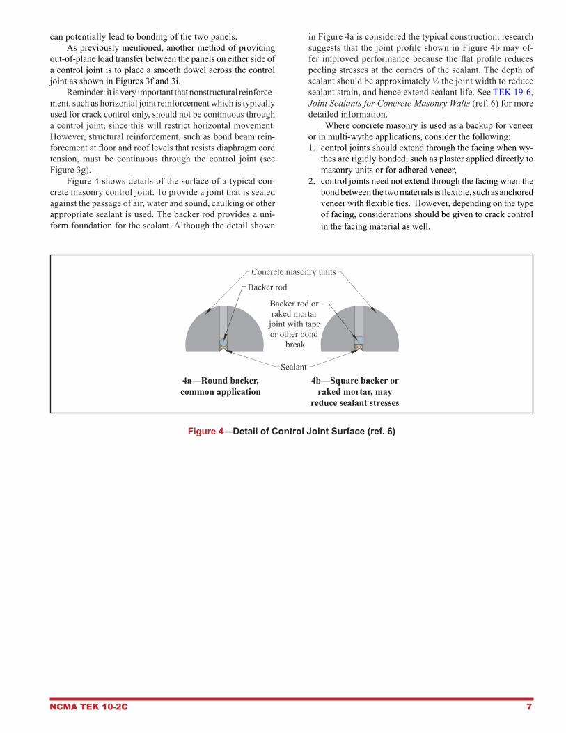
can potentially lead to bonding of the two panels. As previously mentioned, another method of providing out-of-plane load transfer between the panels on either side of a control joint is to place a smooth dowel across the control joint as shown in Figures 3f and 3i. Reminder: it is very important that nonstructural reinforce-ment, such as horizontal joint reinforcement which is typically used for crack control only, should not be continuous through a control joint, since this will restrict horizontal movement. However, structural reinforcement, such as bond beam rein-forcement at floor and roof levels that resists diaphragm cord tension, must be continuous through the control joint (see Figure 3g). Figure 4 shows details of the surface of a typical con-crete masonry control joint. To provide a joint that is sealed against the passage of air, water and sound, caulking or other appropriate sealant is used. The backer rod provides a uni-form foundation for the sealant. Although the detail shown
in Figure 4a is considered the typical construction, research suggests that the joint profile shown in Figure 4b may of-fer improved performance because the flat profile reduces peeling stresses at the corners of the sealant. The depth of sealant should be approximately ½ the joint width to reduce sealant strain, and hence extend sealant life. See TEK 19-6, Joint Sealants for Concrete Masonry Walls (ref. 6) for more detailed information. Where concrete masonry is used as a backup for veneer or in multi-wythe applications, consider the following:1. control joints should extend through the facing when wy-
thes are rigidly bonded, such as plaster applied directly to masonry units or for adhered veneer,
2. control joints need not extend through the facing when the bond between the two materials is flexible, such as anchored veneer with flexible ties. However, depending on the type of facing, considerations should be given to crack control in the facing material as well.
Figure 4—Detail of Control Joint Surface (ref. 6)
4a—Roundbacker, 4b—Squarebackerorcommonapplication rakedmortar,may reducesealantstresses
Concrete masonry units
Sealant
Backer rod
Backer rod or raked mortar
joint with tape or other bond
break

8 NCMA TEK 10-2C
NCMA and the companies disseminating this technical information disclaim any and all responsibility and liability for the accuracy and the application of the information contained in this publication.
NATIONAL CONCRETE MASONRY ASSOCIATION13750 Sunrise Valley Drive, Herndon, Virginia 20171
www.ncma.org
To order a complete TEK Manual or TEK Index, contact NCMA Publications (703) 713-1900
REFERENCES1. Clay and Concrete Masonry Banding Details, TEK 5-2A. National Concrete Masonry Association, 2002. 2. Control Joints for Concrete Masonry Walls—Alternative Engineered Method, TEK 10-3. National Concrete Masonry Associa-
tion, 2003.3. Crack Control for Concrete Brick and Other Concrete Masonry Veneers, TEK 10-4. National Concrete Masonry Association,
2001.4. Standard Specifications for Loadbearing Concrete Masonry Units, ASTM C90-09. ASTM International, 2009.5. Fire Resistance Rating of Concrete Masonry Assemblies, TEK 7-1C. National Concrete Masonry Association, 2009.6. Joint Sealants for Concrete Masonry Walls, TEK 19-6. National Concrete Masonry Association, 2008.7. Standard Specification for Nonrigid Vinyl Chloride Polymer and Copolymer Molding and Extrusion Compounds, ASTM D2287-
96(2001). ASTM International, 2001.8. Standard Classification System for Rubber Products in Automotive Applications, ASTM D2000-08. ASTM International, 2008.