state of the art for strengthening masonry … · blocks) and mortar. basically, the interventions...
TRANSCRIPT

BULETINUL INSTITUTULUI POLITEHNIC DIN IAŞI Publicat de
Universitatea Tehnică „Gheorghe Asachi” din Iaşi Tomul LVIII (LXII), Fasc. 2, 2012
Secţia CONSTRUCŢII. ARHITECTURĂ
STATE OF THE ART FOR STRENGTHENING MASONRY WITH FIBRE REINFORCED POLYMERS
BY
CRISTINA E. LANIVSCHI*
“Gheorghe Asachi” Technical University of Iaşi Faculty of Civil Engineering and Building Services
Received: February 21, 2012 Accepted for publication: April 30, 2012
Abstract. This paper addresses the modern strengthening techniques used
for improving the earthquaqe behaviour of masonry structures, by aid of fibre reinforced polymers (FRP). These type of materials play an important role in the process of overtaking the tensile stresses which masonry by itself is not capable to resist. Also, they proved to have a very good bond strength, both for normal and tangential stresses, with respect to masonry units (fired clay bricks, concrete blocks) and mortar. Basically, the interventions on existing masonry may be concentrated in joints, starting with joints repointing or near surface mounted (NSM), reinforcing techniques, or may be applied on the entire wall or structure, mentioning here jacketing, post-tensioning or center core techniques. Even though structural repointing presents less influence in terms of strength to in and out-of-plane loading than overall applied techniques, their main advantage is represented by the possibility to preserve the original aspect of the masonry. More over, new strengthening materials developed, like fibre reinforced mortars and/or polymer modified mortars, which might successfully fulfill masonry structures requirements.
Key words: masonry; FRP strengthening.
1. Introduction
Masonry is a high complexity construction material due to the great
diversity of types and properties of materials used to build it. In the design *e-mail: [email protected]

98 Cristina E. Lanivschi
norms, the tensile strength of masonry is usually neglected, the structure being conceived so that the walls to work mostly in compression and with very limited shear force capacity.
The strengthening approaches may be concentrated in joints, which are the weak planes for masonry, or may concern the entire masonry structure, respectively a structural wall.
Besides the traditional methods of strengthening the masonry, this paper addreses the use of FRP, as they gained a high interest in the scientific world, both because of their reduced weight and increased strengths.
The most important reason to choose among these modern or innovative reinforcing techniques is the necessity to considerable increase the masonry strength, which may only be achieved by use of much more efficient materials than the original ones.
Reinforced plasters and the application of FRP composite materials are placed in the group of interventions with reduced/small mechanical compatibility with the support, due to its high relative stiffness which significantly alters/influences the characteristic stiffness and strength of the masonry wall.
The high durability is very attractive for applications where steel deteriorates rapidly (e.g. corrosion of reinforcing bars in bridges and parkades). One drawback is the susceptibility of the resin in FRP’s to ultraviolet light. The resin slowly becomes brittle – often seen in plastic objects as they “weather” over the years when exposed to sunlight. Thus, FRP must be protected from exposure to direct sunlight, which can easily be achieved indoors and with paint. New resin formulations are being developed which will not suffer from this problem (Shrive, 2004).
For the construction industry, FRP’s are available in sheets, strips, tendons (for pre- or posttensioning) and reinforcing bars and meshes. If all the fibres are aligned in the longitudinal direction of the sheet, strip, tendon or rod, then highly anisotropic behaviour is obtained. Very high strength and much greater stiffness occur in that direction compared to others. Some sheets are now available with multidirectional fibres, providing more orthotropic properties, and other structures can be specifically filament–wound to give desired multidirectionality to the fibres (Ibrahim et al., 2000).
2. Structural Strengthening of Masonry Walls
2.1. Surface Coatings
The technology consists of cleaning both faces of the wall, removing
the dust and any loose particles by high air pressure and followed by a standard wet laying-up procedure to bond textile sheets on both sides of the wall and

Bul. Inst. Polit. Iaşi, t. LVIII (LXII), f. 2, 2012 99
cover the entire surface by using a bonding agent. For specimens receiving mortars, the wall surface is previously dampened. Than, the bonding of the textile is made by hand and roller pressure. The bonding agent is applied in 2 mm thick layers with a smooth metal trowel and the textile is pressed slightly into the mortar which protrude through all the perforations between fiber rovings (Fig. 1).
a) Using mortar as binder
The bonding agent using mortar as binder is obtained by using a
commercial inorganic dry binder, with cement polymer ratio of 10:1 by weight and the binder water ratio of 3.3:1 by weight. The compressive strength is of 31.36 MPa and flexural strength of 5.77 MPa (Papanicolaou et al., 2008).
Fig. 1 – Reinforcing masonry by textile embedded in cementitious mortar (Papanicolaou et al., 2008).
For the wallets tested in out-of-plane bending, with plane of failure
parallel to the bed joints, the displacement amplitudes increased and debonding of brick bed joint interfaces close to the mid-span was detected. Untill the onset of 10th displacement cycle the panel showed no other signs of severe damage. The cementitious matrix allowed the formation of almost evently distributed fine cracks on the coated surface, parallel to the bed joints. The low tensile capacity of the cementitious matrix and the resulting distributed cracking led to a more compliant response, enabling the wall to develop higher deflections at failure and to fail at a higher load. Failure occured in the 11th cycle, through the formation of diagonal cracks. At larger displacements, reversals the brick adjacent to the crack crushed and the crack propagated through the masonry-

100 Cristina E. Lanivschi
textile reinforced mortar (TRM), interface, causing controlled debonding of the textile reinforcement. The maximum load obtained was of 12.22 kN, with a corresponding displacement of 10.7 mm. With a doubled number of textile sheets, the maximum load attained was of 15.15 kN and the displacement of 44%, lower than the one obtained with only one sheet of textile.
For the wallets tested in out-of-plane bending with failure perpendicular to the bed joints, during the early cycles of the response, diagonal cracking occured. This cracking pattern became critical and marked the failure mechanism for the doubled number of textile layers. For a single layer of textile, the failure occured due to tensile fracture of the textile at midspan. A gradual tensile fracture of the TRM jacket in the pull direction was observed. The maximum load undertaken by the system was of 14.42 kN and a corresponding displacement of 9.45 mm.
b) Using epoxy resin as binder
For the specimens receiving adhesive bonding a two-part epoxy resin
with a mixing ratio 4:1 by weight adhesive was used with a tensile strength of 30 MPa and an elastic modulus of 3.8 GPa. The adhesive was pasty with a viscosity such that complete wetting of the fibers in the textile was possible by using a plastic roller (Papanicolaou et al., 2008).
For out of plane bending with plane of failure parallel to the bed joints, the failure mechanism was governed by hairline flexural cracks near the midspan and signs of brick-bed joint debonding, the full development of which was prevented by the tensile reinforcement. At cycle 6, in the push direction, 6 mm piston displacement amplitude, a diagonal crack was found and propagated towards the loading line. Upon load reversal, a mirror-but less extensive crack was formed, resulting in notable strength and stiffness degradation in the push direction, whereas in the pull direction the respective degradations were less pronounced. Whilst the X-shaped cracking pattern, typical of fully reversed loading conditions, was nearly symmetrical to the specimens longitudinal axis, this was not the case with respect to specimen`s centerline because damage was localized in one of the shear panels. At higher displacements amplitudes the cracks chaused the brick webs to gradually crush and the textile layer to debond from the core brickwork. Excellent brick to textile bond was observed as the outer brick shells were firmly attached to the debonded reinforcement layer. The maximum load recorded until failure was of 10.02 kN, with a corresponding displacement of 4.45 mm at midspan. For the two TRM layers, the failure occured due to formation of large diagonal cracks, the load capacity of the specimen being drastically reduced. The maximum load, of 12.94 kN, was with only 30% increased and the displacement dicreased with 16%. The samples presented a steeper ascending branch and reduced deformability.

Bul. Inst. Polit. Iaşi, t. LVIII (LXII), f. 2, 2012 101
For out-of-plane bending with failure perpendicular to the bed joints, following the formation of diagonal cracks close to the maximum moment line, the FRP jacket of specimen with one textile reinforcement failed suddenly in tension during 13th displacement cycle in the pull direction. The maximum load obtained was of 17.82 kN and the corresponding displacement of 11.02 mm.
2.2. Application of FRP Strips
The system consists of using strips of composite material, glass fibers
and epoxy resin matrix, with/without connectors to stick together the strips from both sides of the wall (Candeias et al., 2005), applied in two layers with the composite strips oriented after the pricipal directions of tensile stresses (Fig. 2).
Layer – 1st coat
Mortar groove
Layer – 2ed coat
Fig. 2 – Reinforcing masonry by FRP strips with/without
connectors (Candeias et al., 2005).
Another system used to strengthen masonry consists of using sheets of unidirectional carbon fiber or glass fiber (Borri et al., 2003) placed on both sides of the panel, following the scheme presented in Fig. 3.
Fig. 3 – Reinforcing masonry with unidirectional carbon/glass fibers sheets and layout of diagonal compression tests (Borri et al., 2003).
102 Cristina E. Lanivschi
Due to the great irregularity in the masonry texture, the strengthening of the panels was carried out only after spreading a layer of cement based mortar to create a sufficiently plane, uniform surface on which the composite was then applied. The mortar used was placed directly on the masonry once the original rendering had been removed.
The results of shear-compression tests showed an increase in the strength, τk , of the strengthened panels, relative to those non-strengthened, of approximately 55%, independent of the type of fibers used. This essentially depends on the particular modality of failure, which did not involve the crisis of the composite, except at a limited area on some of the panels. In fact, the fibers remained attached to the cement-based mortar, used to create a uniform surface on which the FRP was applied, which in turn had detached from the masonry. Therefore, since the state of fiber stress was well below its failure level, it was only marginally engaged. For this reason, no difference resulted from the use of carbon fibers or fiber glass. However, in the successive diagonal compression tests the layer of mortar was replaced by a thinner layer of epoxy putty which bonded more efficiently with the masonry substrate and determined a better utilization of the fibers, which did not detach until the masonry-composite system failure was reached.
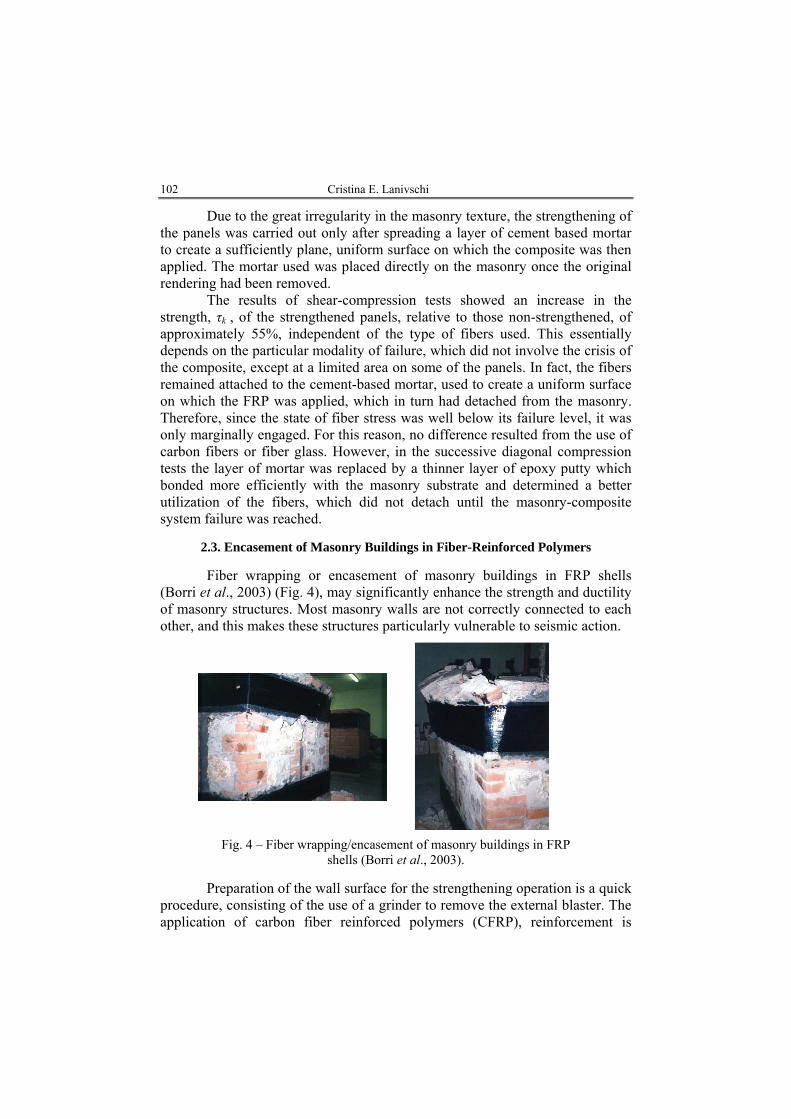
2.3. Encasement of Masonry Buildings in Fiber-Reinforced Polymers
Fiber wrapping or encasement of masonry buildings in FRP shells
(Borri et al., 2003) (Fig. 4), may significantly enhance the strength and ductility of masonry structures. Most masonry walls are not correctly connected to each other, and this makes these structures particularly vulnerable to seismic action.
Fig. 4 – Fiber wrapping/encasement of masonry buildings in FRP
shells (Borri et al., 2003).
Preparation of the wall surface for the strengthening operation is a quick procedure, consisting of the use of a grinder to remove the external blaster. The application of carbon fiber reinforced polymers (CFRP), reinforcement is
Bul. Inst. Polit. Iaşi, t. LVIII (LXII), f. 2, 2012 103
carried out after having spread an epoxy-primer and an epoxy-mortar on the surface of panels. Two bands of CFRP are applied along the external perimeter in order to wrap the masonry cell with one band near the base and with another near the upper border.
The solid brick and the stone masonry cells failed at a load of 70 kN and, respectively, of 90 kN. The low flexural stiffness of the CFRP sheet caused large lateral deformations at the maximum load. The experiment showed that the FRP reinforcement maintains its effectiveness until the crushing strain of masonry is attained.
A significant consequence of the presence of the FRP reinforcement was the absence of the out-of-plane collapse of the masonry wall. The FRP sheet was in fact able to contain the stones and bricks resulting from the crumbling of the masonry wall.
The process of the crumbling of the masonry panel started long before the maximum load was reached. At the maximum load, large deformations were measured highlighting the high ductility characteristics of the masonry reinforced with CFRP polymers. The use of the two CFRP sheets placed one upon the other (the total number of sheets used is four, considering that two bands of two sheets were placed around the masonry cell) did not cause problems at the four angles.
Several strain gauges were fixed along the FRP sheets in order to measure the stress tensile status of the composite (Fig. 4). This allowed us to confirm that the FRP reinforcing technique carried out its strengthening action, as well as to measure the degree of utilization of the FRP.
However, the abrupt variation in curvature occurring at the four angles of the masonry cells should be avoided. CFRP sheets have a high degree of weakness due to the onset of stress at right angles to the fibres. In this case, the problem was partially solved thanks to the introduction of steel L shapes characterized by a radius of curvature of 20 mm.
2.4. Use of Polymer Grids
The reasons for which polymer grids may be successfully applied for
restoring masonry are, from mechanical point of view, the elastic and plastic properties which present quite the same proportions. Due to the fact that these two materials have similar moduli of elasticity, they will deform in similar manner, while the grids supply the system with convenient levels of strength and high capacity of dissipation of energy (Sofronie, 2004). From geometric point of view, the grids are shaped as bars of equal tension strength on the two principal directions. The ribs are stiff enough to transmit both tension and shear stresses, while the joints are solid and together with the ribs are integrated in grids. From physical and environmental reasons, the grids are inert to all

104 Cristina E. Lanivschi
chemicals found in mortars and have no solvents at ambient temperatures. Also, the polymer grids present great durability, as provided by the producer.
The applications of these grids may differ, from embedding them in bed joints, confining the masonry by wrapping around with polymer grids and then by rendering either building bodies as such or only some of their structural members (Fig. 6).
a b
Fig. 6 – Polymer grids used to: a – confine masonry, b – wrapping around the masonry building, as presented by Sofronie (2004).
Masonry reinforced with polymer grids in bed layers presents increased bearing capacity to compression and shear forces. It is worth mentioning that, as a consequence of reinforcing masonry in bed layers, the 45º inclined cracks no longer occur. Often the same thing happends even when not all horizontal joints of masonry are reinforced but only some, for instance, at three or five bed joints. However, the polymer grids act only in horizontal planes in spite of the fact that some of their effects influence masonry`s properties also on vertical direction.
2.5. FRP Grids Embedded in Cementitious Matrix
The grid used for the strengthening system is a bi-directional AR-glass
coated open grid, consisting of machine and cross direction strands connected perpendicularly at about 25.4 mm spacing. The grid cross sectional area per rib is of 0.896 mm2, based on glass cross sectional area both in machine and cross direction, where “ribs” are defined as continuous elements of a grid, which are
Bul. Inst. Polit. Iaşi, t. LVIII (LXII), f. 2, 2012 105
either in the machine of crossmachine direction as manufactured. The mechanical properties of the grid are of 1,276 MPa tensile strength, 72 GPa Young’s modulus and 1.78% ultimate strain, as provided by the manufacturer. This fabric was embedded in a cementitious matrix, which is a fiber reinforced polymer-modified masonry mortar produced by mixing Portland cement based proprietary formulation using 12.7 mm long chopped AR glass fibers (Prota et al., 2006). The matrix was a ready mix masonry mortar, consisting of a cementitious matrix, polymeric admixture and water. The mechanical properties of the matrix after 28 days were of 24.1 MPa compressive strength and 5.5 MPa flexural strength.
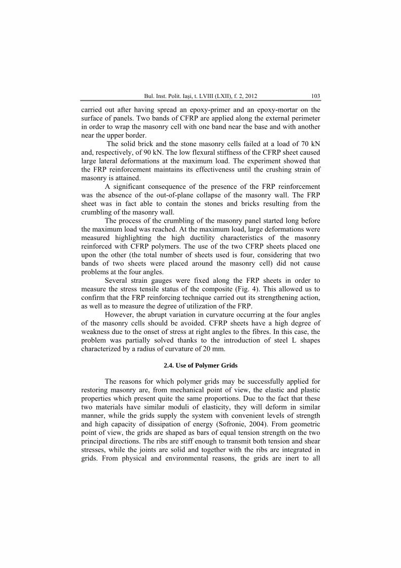
The strengthening system was installed as follows: the wall was properly prewetted and the mortar, previously mixed with water and an acrylic fortifier, was then troweled onto the wall with a 5 mm thick layer. The first 900 mm2 fabric sheet was firmly hand pressed into the wet binder to ensure its adequate embedding to the support wall. The first ply was laid up with the primary fibers aligned horizontally to the bottom of the wall (Fig. 7 a). Then, a second layer of mortar was applied by troweling an additional 5 mm thick layer. Finally, the second ply was applied with the primary fibers aligned vertically and covered by a relatively smooth surface, the resulting cement based matrix coated alkali-resistant glass grid system, CMG system, nominal thickness being of about 10 mm (Fig. 7 b).
a b
Fig. 7 – CMG system: a – grid installation; b – applying the final mortar layer (Prota et al., 2006).
For the panels with the CMG system applied only on the face, at the
ultimate stage, the stress field in the as-built panels tend to force the fracture

106 Cristina E. Lanivschi
cracks to follow the line of least resistance rather than the line of action of the splitting load. For some panels, the failure resulted in mortar bed and head joint failure. Thus, shear capacity is governed by the weak bond between mortar and units – tuff stones. For some other panels, the failure plane had a marked stepped appearance due to a combination of debonding along the mortar joints
a
b c
Fig. 8 – CMG system applied on one face of the panels: a and b – failure patterns on unstrengthened and strengthened side; c – out-
of-plane deformation (Prota et al., 2006).
and tensile failure of units (Fig. 8 a). This is the reason for the higher shear strength obtained. In fact, the failure plane ran through a greater surface compared to the case of sliding along the mortar joints and caused the full splitting of the panel. For the strengthened face, the CMG system provided a distribution of stresses along the loading line (Fig 8 b), causing the out-of-plane failure of the panel, as seen in Fig. 8 c. Although higher stress concentration was induced by the test setup at the loaded edges, no local failure close to the loading shoes was observed.

Bul. Inst. Polit. Iaşi, t. LVIII (LXII), f. 2, 2012 107
The presence of a double layer of CMG on both sides changed the mode of failure of panels from a shear slip along the mortar joints to a more uniform crack pattern along the splitting line. The elastic modulus of glass fibers led to a better redistribution of the lateral load on the panel, resulting a more uniform stress state and higher energy absorption provided by the reinforcing grid (Fig. 9). The panel kept its structural integrity throughout the entire test and it would have been able to carry a further load if no local failure close to the loading shoes happened. Shear strength response of the walls was governed by masonry cracking at the loaded edges, therefore the ultimate values determined with the tests represent a lower limit of the shear capacity of the specimens.
Fig. 9 – Crack pattern at failure for CMG system
applied on both sides of the panels (Prota et al., 2006).
Generally, the bond between the masonry and the externally bonded strengthening system plays a critical role in providing adequate load carrying capacity to the whole composite system. This is even more critical when strengthening systems are applied in situ on roughly squared tuff stone surfaces, using the hand layup technique. When the development length of the strengthening system cannot be ensured, adequate mechanical anchorage needs to be installed. Even though no mechanical anchorage system was provided, no premature debonding of CMG reinforcement occurred.
2.6. Post-Tensioning
The system consists of placing FRP tendons inside a steel tube (duct)
either within holes drilled along the midplane of the wall or along grooves

108 Cristina E. Lanivschi
symmetrically cut on both surfaces of the wall (Reda Taha & Shrive, 2003). Holes are cement grouted and external grooves are filled with shotcrete (Fig. 10).
Anchorage of post-tensioning in masonry is more complicated than in reinforced concrete, as masonry has a relatively low compressive strength. The self-activating dead end can be encasing to continuous and heavy reinforced concrete foundation beams, constructed on either side of the wall bottom and connected well with it (ElGawady et al., 2004). At the top, post-tensioning is anchored in the existing or new reinforced concrete elements or specially stiffened steel plates. Anchorage devices and plates are usually placed in a recess of the surface and covered later on with shotcrete or cement mortar. The requirement for bottom anchorage penalizes considerably this retrofitting technique. A major problem encountered for this system is the anchorage of the tendons. Standard anchors for steel tendons rupture CFRP tendons very easily.
a b c Fig. 10 – a – Post-tensioning using FRP; b – flexural crack in post-tension
wall; c – post-tensioning jacking frame (ISIS) (ElGawady et al., 2004).
Post-tensioning increases both the cracking moment of resistance and the ultimate moment of masonry walls, so has some attraction for application in seismic areas. However, there would be a need in design to have some component of the masonry fail in a stable manner at ultimate rather than the prestressing tendon.
2.7. Center Core Technique
This reinforcing method is derived from a traditional one and provides the wall with a capacity to resist both in-plane and out-of-plane loading (ElGawady et al., 2004).
The center core system consists of a reinforced, grouted core placed in the center of an existing URM wall. A continuous vertical hole is drilled from the top of the wall into its basement wall. The core achieved by this oil-well drilling technique may be of 50…125 mm in diameter, depending on the

Bul. Inst. Polit. Iaşi, t. LVIII (LXII), f. 2, 2012 109
thickness of the unreinforced masonry wall and the retrofitting required. With existing technology, this core can be drilled precisely through the entire height of two or three-story masonry wall. The drilling is a dry process with the debris removal handled by a vacuum and filter system that keeps the dust to a minimum. After placing the reinforcement in the center of the hole, a filler material is pumped from the top of the wall to the bottom such that the core is filled from the bottom under pressure controlled by the height of the grout. The placement of the grout under pressure produced by the height of the core provides a beneficial migration of the grout into all voids adjacent to the core shaft. The strong bonding of the grout to the inner and outer wythes of brick provides a homogeneous structural element much larger than the core itself .
Wall anchors for lateral ties to the roof and floors are placed at the core location to make a positive connection to the wall. The filler material itself consists of a binder material (e.g. epoxy, cement, polyester) and a filler material (e.g. sand). Shear tests performed for such strengthening techniques showed that specimens made with cement grout were generally 30% weaker than specimens made with sand/epoxy or sand/polyester grouts. However, based on material price, it is recommended to use polyester and to keep the sand-polyester volume ratio between of 1:1 and 2:1.
This technique is successfully used to double the resistance of unreinforced masonry wall in a static cyclic test. Although the high lateral displacement achieved during the test, the energy dissipated was limited. The tensile yield of the bar did not occur due to the bar anchorage problem. However, the system has several advantages: it will not alter the appearance of wall surface as well as the function of the building will not be impaired since the drilling and reinforcing operation can be done externally from the roof. The main disadvantage is that this technique tends to create zones with widely varying stiffness and strength properties.
3. Structural Repointing of Masonry Walls Structural repointing addresses mainly the interventions in joints by
replacing some of the material from which they are made with FRP systems conceived to improve the capacity of URM wall to overtake loadings developed both in or out-of-plane. The main advantage of these systems is that the original aspect of the wall is not affected.
3.1. Epoxy Injections
The scope of injections is to restore the original integrity of the
retrofitted wall and to fill the voids and cracks, which are present in the masonry due to physical and chemical deterioration and/or mechanical actions. The epoxy injection is a method used for small cracks (ElGawady et al., 2004).

110 Cristina E. Lanivschi
The success of this technique depends on the injectability of the mix used and on the injection technique adopted. The injectability of the mix, mix`s mechanical properties and its physical chemical compatibility with the masonry to be retrofitted are important aspects to be considered for this consolidation technique.
Walls retrofitted with epoxy injection tend to be stiffer than the un-retrofitted, but the increase in stiffness (10%…20%) (ElGawady et al., 2004), is much less dramatic than the increase in strength. The increment in lateral resistance ranged from 2…4 times the un-retrofitted resistance. The use of epoxy resins can be advisable when a through study of the structural consequences of such an increment in strength in selected portions of the building shows that there is no danger of potential damage to other portions.
3.2. Joints Reinforcement
The scope of reinforcing the joints, as they represent the weak planes of
masonry, is to increase the tensile strength of the bed joints and reduce and distribute more uniformly the transverse tensile stresses in the brick because of the inhibition of lateral expansion of the mortar within the bed joint.
a) Micro reinforcement of masonry joints
The micro-reinforcement of masonry joints may be achieved by adding in the cement lime reach mortar mix short polypropylene/polymer fibers of 6 mm length (Bosiljkov, 2006). The objective of the technique is to reduce cracks induced by the process of mortar hardening and to improve mortar toughness and flexibility.
The results obtained for compression showed that the compression strength increased at least with 15% and the modulus of elasticity is lower than of cement lime reach mortar. In tension, no significant influence (for diagonal compression test) was observed. In case of shear, very compact overall behavior occurred, shear cracks appeared shortly before rocking in the direction of main compressive stresses, without a single pronounced crack, but with many closely spaced shear cracks passing both through the unit and the bed joints. At failure, head joints were not properly filled due to problems of the workability of the fresh mortar.
b) Macro reinforcement of masonry joints
The method consists of introducing two layers of cement lime reach mortar with an embedded resin coated glass fiber mesh between them (Bosiljkov, 2006). The expected improvement are similar to the micro-reinforcement of joints.
Bul. Inst. Polit. Iaşi, t. LVIII (LXII), f. 2, 2012 111
In compression, the strength increased at least with 15% and the modulus of elasticity being lower than of cement lime reach mortar. In tension, the tensile strength increased, for diagonal compression test and the samples presented the most ductile behaviour. In shear, overall behaviour up to the beginning of opening of shear cracks was almost the same as for using cement-lime mortar – same level of lateral force and a more uniformly distributed tensile strains within the unit itself – dense crack. A much more ductile behaviour with stronger ability to dissipate the energy (area of hysteresis loops) were achieved. Beginning of cracking mechanism did not provoke the failure of the specimens. Failure seemed to be a consequence of the stiffening of the masonry material within the middle third of the specimen resulting, sometimes, in an explosive collapse.
c) Near Surface Mounted (NSM) Techniques
The method consists in cutting grooves in the bed joints, cleaned and filled with a cement-based mortar. The FRP strips are seated on face and fully embedded using a mortar comprised in three parts: liquid compounds, A and B (epoxy resin suspensions) and solid compounds, C (cement and cementitious materials), in an A:B:C of 1.14:2.86:17 proportion by weight, with the compression strength of 40 MPa and flexural strength of 9 MPa. The strips have 2 × 16 mm cross section, furnished in 76 m long spools consisting of carbon fibres in a bisphenol epoxy vinylester resin matrix, with tensile strength of 2,070 MPa, modulus of elasticity of 125 GPa and ultimate strain of 17% (Bosiljkov, 2006).
The results for out-of-plane bending with failure perpendicular to the bed joints revealed extensive flexural cracking mainly at mid-span, followed by controlled debonding of the NSM strips. Development of longitudinal splitting cracks in the position of NSM strips along the bed joints was observed. The maximum load obtained was of 12.95 kN with 17.16 mm displacement. Increasing the number of strips, the flexural-shear cracking was a bit more distributed, with maximum load of 15.87 kN and a corresponding 17.16 mm displacement. Severe damage occurred to the outer course of bricks and buckling of the outermost NSM strip in compression near the mid-span, in the vicinity of the displacement traducer. As a conclusion, more ductile response characteristics were presented, but the method proved to be less effective in strength but more effective in deformability than both TRM and FRP jacketing.
This method may also use embedded FRP bars and suitable epoxy based paste in the mortar joints. To prevent tilting or twisting of the strengthened wall, the FRP reinforcement should be installed symmetrically on both faces of the wall.
The predominant mode of failure of the FRP bars is debonding at the paste–masonry interface. The average obtained bond strength is about 1.76 MPa.

112 Cristina E. Lanivschi
The failure for one side retrofitted wall is composed of two phases: in plane failure which gives the strength of the element and the out-of-plane failure which characterizes stability if the wall cracks development starting from the unreinforced face toward the reinforced face, causing the tilting of the wall.
The horizontal reinforcement constrains the diagonal tensile cracking resulting in attainment of higher average shear stresses in the wall and development of diagonal struts. When load increases and the horizontal reinforcement is no longer sufficient to adequately transfer the tensile stresses across the diagonal cracks, the latter cracks widen and trigger shear failure due to progressive bond failure at the masonry–paste interface in the reinforced joints and attainment of the ultimate capacity of the reinforcement. The failure occured by shear sliding along the bed joint. Pseudo-ductility is much lower than that of stepped diagonal tension failure and the method proved better stability for specimens with alternately symmetrical reinforcement on both faces.
4. Conclusions
The alteration of climate conditions, the different changes in the
exploitation of the building as well as the repeated seismic activity at rather reduced intervals of time are followed by major degradations of the strength of structural masonry.
The modern practice solutions include high performance materials of construction, like glass fiber reinforced polymers and/or various polymeric mortar and putty.
On the international scale, several remedial measures are applied to the damaged masonry structures: injecting the micro-cracks with synthetic thermally rigid or thermsally plastic resins, sticking strips of composite nature, for example peroxide resins reinforced with carbon/glass/aramide fibers on the surface of the wall, the number and position of strips being imposed by structural designing. These strips may be stacked to both sides of the wall and bond together by means of anchors.
For all systems of repairing masonry, the connection of high performance materials based on fibers to masonry need the use of another material to make the bond development possible. If such bond is not effective, a discontinuity occurs and the strengthening system becomes unable to resist external loads from earthquake and winds. Though consolidated, the element failure will develop by increasing the number of cracks in the original material followed by the detaching of the composite material from the structure.

Bul. Inst. Polit. Iaşi, t. LVIII (LXII), f. 2, 2012 113
REFERENCES
Borri A., Corradi M., Vignoli A., Seismic Upgrading of Masonry Structures with FRP.
http://www.strutture.unipg.it/scienza/pdf/101.pdf, 2003. Bosiljkov V., Micro vs. Macro Reinforcement of Brickwork Masonry. Mater. a. Struct.,
39, 235–245 (2006). Candeias P., Costa A.C., Coelho E., Seismic Strengthening of Old Masonry Buildings
with Application of GFRP’s. 1st US-Portugal Internat. Workshop on Grand Challenges in Earthquake Engng. 250 Years after the 1755 Lisbon Earthquake, Lamego, Portugal, 2005.
ElGawady M., Lestuzzi P., Badoux M., A Review of Conventional Seismic Retrofitting Techniques for URM. 13th Internat. Brick a. Block Masonry Conf., Amsterdam, July 4-7, 2004.
Ibrahim S., Polyzois D., Hassan S.K., Development of Glass Fiber Reinforced Plastic Poles for Transmission and Distribution Lines. Canad. J. of Civil Engng., 27, 5, 850-858 (2000).
Papanicolaou C.G., Triantafillou T.C., Papathanasiou M., Karlos K., Textile Reinforced Mortar (TRM) versus FRP as Strengthening Material of URM Walls: Out-Of-Plane Cyclic Loading. Mater. a. Struct., 41, 143-157 (2008).
Prota A., Marcari G., Fabbrocino G., Manfredi G., Aldea C., Experimental In-Plane Behavior of Tuff MasonryStrengthened with Cementitious Matrix–Grid Composites. J. of Comp. for Constr. © ASCE , 10, 3, 223-233 (2006).
Reda Taha M.M., Shrive N.G., New Concrete Anchors for CFRP Post-Tensioning Tendons. Part I: State-of-the-art Review/ Design. ACI Struct. J., 100, 1, 86-95 (2003).
Reda Taha M.M., Shrive N.G., New Concrete Anchors for CFRP Post-Tensioning Tendons. Part II: Development and Experimental Investigation. ACI Struct. J., 100, 1, 96-104 (2003).
Shrive N.G., Use of Fibre Reinforced Polymers to Improve Seismic Resistance of Masonry. Proc. of the 6th National Congress on Seismol. a. Seismic Engng. SÍSMICA 2004, Portugal, 2004, vol. 1, 197-208.
Sofronie R.A., Seismic Strengthening of Masonry in Buildings and Cultural Heritage. Proc. of the 6th National Congress on Seismol. a. Seismic Engng. SÍSMICA 2004, Portugal, 2004. Vol. 1, 81-100.
SISTEME DE CONSOLIDARE A ZIDĂRIILOR UTILIZÂND MATERIALE COMPOZITE
(Rezumat)
Se prezintă o sinteză actuală privind metodele moderne de consolidare a
structurilor din zidărie, prin utilizarea sistemelor pe bază de poliesteri armaţi cu fibre (PAF), în scopul imbunătăţirii comportării la seism a acestora. Materialele compozite PAF joacă un rol important în procesul de preluare şi redistribuire a tensiunilor din

114 Cristina E. Lanivschi
solicitarea de întindere, cunoscut fiind faptul că zidăria nu se comportă satisfăcător la acest tip de solicitare. În literatura de specialitate s-a evidenţiat faptul că aderenţa dintre PAF şi blocurile de zidărie, respectiv mortar, la solicitări de întindere cât şi de forfecare este, în general, foarte bună. În principiu, intervenţiile asupra zidăriei existente din construcţii situate în zone seismice pot fi localizate în rosturi, constând în refacerea sau armarea în suprafaţă a acestora. De asemenea, sistemele de consolidare pot fi aplicate la nivelul întregii structuri, menţionând aici cămăşuirea, post-tensionarea sau tehnica sâmburelui central. Deşi refacerea rosturilor conduce la o influenţă relativ redusă asupra rezistenţei la solicitări în planul elementului şi perpendicular pe acesta, principalul lor avantaj constă în posibilitatea de a păstra aspectul original al zidăriei aparente. Sinteza de documentare arată că în ultima perioadă s-au dezvoltat noi materiale pentru consolidări, mortare armate cu fibre şi/sau mortare polimerice care, utilizate la consolidarea zidăriilor, pot satisface cerinţele structurale de rezistenţă, stabilitate şi siguranţă în exploatare a structurilor din sisteme de zidării consolidate.