contents vision 30 maintenance manual · 4 contents previous page first page next page previous...
TRANSCRIPT
Contents
������Camera Control Solutions
Mai
nte
nan
ce M
anu
alNext Page
Previous View
Vision 30P
an an
d T
ilt Head
2
ContentsPrevious
PageFirst Page
Next Page
Previous View
Vision 30PAN AND TILT HEAD
3259
MAINTENANCE MANUALAND
ILLUSTRATED PARTS LIST
PUBLICATION PART No. 3259-9
ISSUE 3
Copyright Vinten Broadcast Limited 1999
All rights reserved throughout the world. No part of this document may be stored in a retrieval system, transmitted, copied or reproduced in any way including, but not limited to, photocopy, photograph, magnetic or
other record without the prior agreement and permission in writing of Vinten Broadcast Limited.
Vinten, Vision and Quickfit are registered trademarks of Vinten Broadcast Limited.
3
ContentsPrevious
PageFirst Page
Next Page
Previous View
Foreword
This manual provides full and detailed maintenance and spare parts information for the Vinten® Vision® 30 pan and tilt head.
It is recommended that this manual is read carefully and the illustrations studied prior to operating or servicing the pan and tilt head. Attention to the details contained herein will ensure that the pan and tilt head will operate efficiently with the minimum of attention over a long service life. Particular attention must be paid to cleaning, especially after use in adverse conditions.
To order spare parts or to obtain further information, application should be made to Vinten Broadcast Limited or to your local distributor.
WARNING!: Read the Safety Section on page 8 before using this pan and tilt head or attempting any adjustment or repair.
NOTE: Information contained in this document is subject to change.Vinten Broadcast Ltd reserves the right, without notice, to make changes in equipment design or performance as progress in engineering, manufacturing or technology may warrant.
4
ContentsPrevious
PageFirst Page
Next Page
Previous View
Notes to readers
This is the on-line version of ‘Vision 30 Pan and Tilt Head Maintenance Manual’ (3259-9). Readers should be aware that the pagination differs between on-line and printed versions.
Navigation
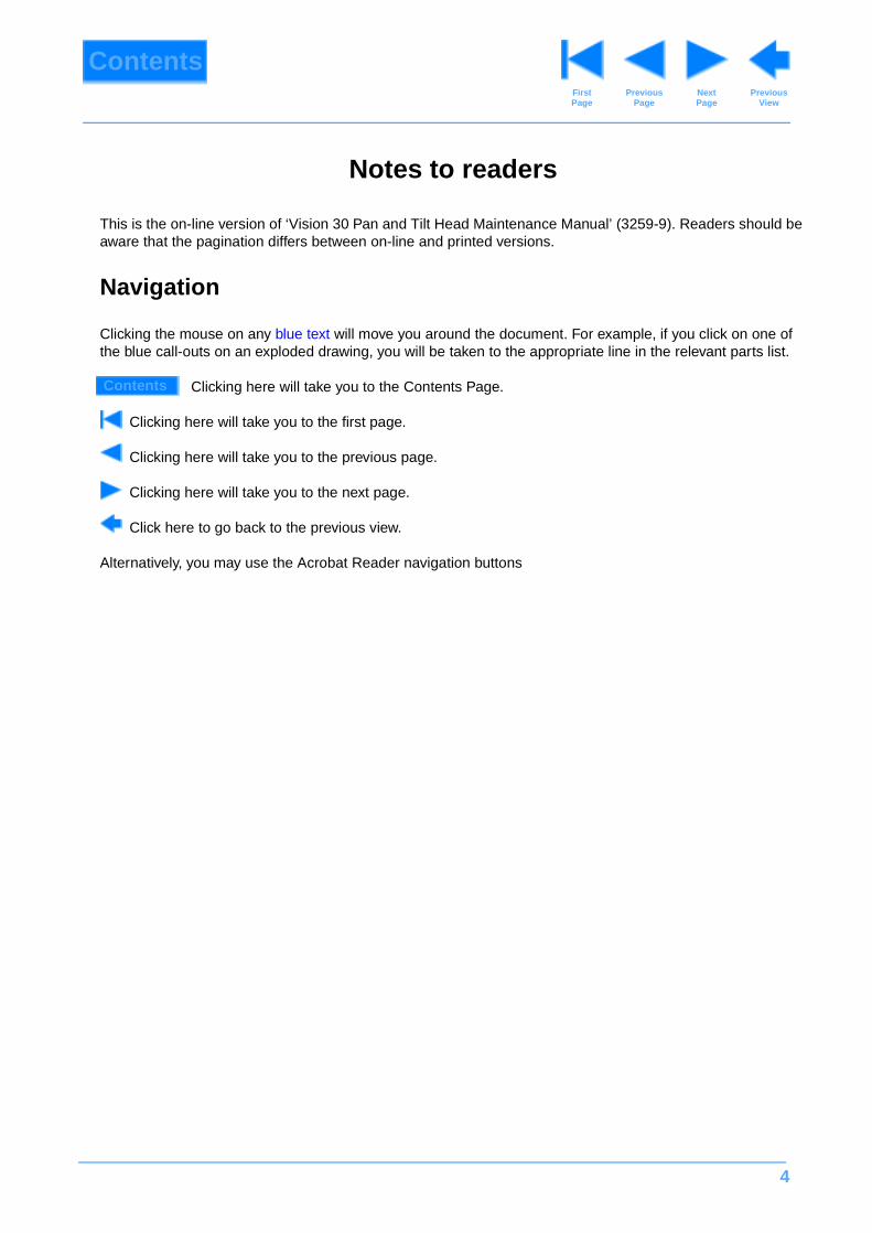
Clicking the mouse on any blue text will move you around the document. For example, if you click on one of the blue call-outs on an exploded drawing, you will be taken to the appropriate line in the relevant parts list.
Clicking here will take you to the Contents Page.
Clicking here will take you to the first page.
Clicking here will take you to the previous page.
Clicking here will take you to the next page.
Click here to go back to the previous view.
Alternatively, you may use the Acrobat Reader navigation buttons
Contents
5
Contents
Page
Previous Page
First Page
Next Page
Previous View
Foreword . . . . . . . . . . . . . . . . . . . . . . . . . . . . . . . . . . . . . . . . . . . . . . . . . . . . . . . . . . . . . . . . . . . . . . . . . . . . . 3
Notes to readers . . . . . . . . . . . . . . . . . . . . . . . . . . . . . . . . . . . . . . . . . . . . . . . . . . . . . . . . . . . . . . . . . . . . . . . 4
Safety - Read This First! . . . . . . . . . . . . . . . . . . . . . . . . . . . . . . . . . . . . . . . . . . . . . . . . . . . . . . . . . . . . . . . . . 8
Abbreviations . . . . . . . . . . . . . . . . . . . . . . . . . . . . . . . . . . . . . . . . . . . . . . . . . . . . . . . . . . . . . . . . . . . . . . . . . 9
Technical Specification . . . . . . . . . . . . . . . . . . . . . . . . . . . . . . . . . . . . . . . . . . . . . . . . . . . . . . . . . . . . . . . . 10
Design Improvements. . . . . . . . . . . . . . . . . . . . . . . . . . . . . . . . . . . . . . . . . . . . . . . . . . . . . . . . . . . . . . . . . . 11
Section 1 - Introduction and Description
Introduction . . . . . . . . . . . . . . . . . . . . . . . . . . . . . . . . . . . . . . . . . . . . . . . . . . . . . . . . . . . . . . . . . . . . . . . 12
Description . . . . . . . . . . . . . . . . . . . . . . . . . . . . . . . . . . . . . . . . . . . . . . . . . . . . . . . . . . . . . . . . . . . . . . . . 12
Section 2 - Operation
General . . . . . . . . . . . . . . . . . . . . . . . . . . . . . . . . . . . . . . . . . . . . . . . . . . . . . . . . . . . . . . . . . . . . . . . . . . 15
Installation
Fitting the head to its support mounting . . . . . . . . . . . . . . . . . . . . . . . . . . . . . . . . . . . . . . . . . . . . . . . 16
Pan bar attachment. . . . . . . . . . . . . . . . . . . . . . . . . . . . . . . . . . . . . . . . . . . . . . . . . . . . . . . . . . . . . . . 16
Fitting a camera to the head . . . . . . . . . . . . . . . . . . . . . . . . . . . . . . . . . . . . . . . . . . . . . . . . . . . . . . . . 16
Balancing the camera . . . . . . . . . . . . . . . . . . . . . . . . . . . . . . . . . . . . . . . . . . . . . . . . . . . . . . . . . . . . . 18
Setting the tilt drag . . . . . . . . . . . . . . . . . . . . . . . . . . . . . . . . . . . . . . . . . . . . . . . . . . . . . . . . . . . . . . . 18
Setting the pan drag . . . . . . . . . . . . . . . . . . . . . . . . . . . . . . . . . . . . . . . . . . . . . . . . . . . . . . . . . . . . . . 18
Setting the pan and tilt brakes . . . . . . . . . . . . . . . . . . . . . . . . . . . . . . . . . . . . . . . . . . . . . . . . . . . . . . 19
Operation . . . . . . . . . . . . . . . . . . . . . . . . . . . . . . . . . . . . . . . . . . . . . . . . . . . . . . . . . . . . . . . . . . . . . . . . . 19
Section 3 - Tools and Materials
Special tools. . . . . . . . . . . . . . . . . . . . . . . . . . . . . . . . . . . . . . . . . . . . . . . . . . . . . . . . . . . . . . . . . . . . . . . 20
Consumable materials . . . . . . . . . . . . . . . . . . . . . . . . . . . . . . . . . . . . . . . . . . . . . . . . . . . . . . . . . . . . . . . 20
Section 4 - Servicing
General . . . . . . . . . . . . . . . . . . . . . . . . . . . . . . . . . . . . . . . . . . . . . . . . . . . . . . . . . . . . . . . . . . . . . . . . . . 21
Cleaning. . . . . . . . . . . . . . . . . . . . . . . . . . . . . . . . . . . . . . . . . . . . . . . . . . . . . . . . . . . . . . . . . . . . . . . . . . 21
Lubrication . . . . . . . . . . . . . . . . . . . . . . . . . . . . . . . . . . . . . . . . . . . . . . . . . . . . . . . . . . . . . . . . . . . . . . . . 21
Brake adjustment . . . . . . . . . . . . . . . . . . . . . . . . . . . . . . . . . . . . . . . . . . . . . . . . . . . . . . . . . . . . . . . . . . . 21
6
Contents (Cont) Page
Previous Page
First Page
Next Page
Previous View
Section 5 - Repair
General . . . . . . . . . . . . . . . . . . . . . . . . . . . . . . . . . . . . . . . . . . . . . . . . . . . . . . . . . . . . . . . . . . . . . . . . . . 25
Repair . . . . . . . . . . . . . . . . . . . . . . . . . . . . . . . . . . . . . . . . . . . . . . . . . . . . . . . . . . . . . . . . . . . . . . . . . . . 26
Platform assembly . . . . . . . . . . . . . . . . . . . . . . . . . . . . . . . . . . . . . . . . . . . . . . . . . . . . . . . . . . . . . . . 26
Top cover . . . . . . . . . . . . . . . . . . . . . . . . . . . . . . . . . . . . . . . . . . . . . . . . . . . . . . . . . . . . . . . . . . . . . . 27
Front cover . . . . . . . . . . . . . . . . . . . . . . . . . . . . . . . . . . . . . . . . . . . . . . . . . . . . . . . . . . . . . . . . . . . . . 28
End plate/adjustment thread assembly. . . . . . . . . . . . . . . . . . . . . . . . . . . . . . . . . . . . . . . . . . . . . . . . 28
Cross members. . . . . . . . . . . . . . . . . . . . . . . . . . . . . . . . . . . . . . . . . . . . . . . . . . . . . . . . . . . . . . . . . . 29
Mechanism block and secondary spring assemblies . . . . . . . . . . . . . . . . . . . . . . . . . . . . . . . . . . . . . 31
Base assembly . . . . . . . . . . . . . . . . . . . . . . . . . . . . . . . . . . . . . . . . . . . . . . . . . . . . . . . . . . . . . . . . . . 33
Pan drag unit assembly. . . . . . . . . . . . . . . . . . . . . . . . . . . . . . . . . . . . . . . . . . . . . . . . . . . . . . . . . . . . 34
Loading bars . . . . . . . . . . . . . . . . . . . . . . . . . . . . . . . . . . . . . . . . . . . . . . . . . . . . . . . . . . . . . . . . . . . . 37
Side plate assembly . . . . . . . . . . . . . . . . . . . . . . . . . . . . . . . . . . . . . . . . . . . . . . . . . . . . . . . . . . . . . . 39
Tilt drag unit assembly . . . . . . . . . . . . . . . . . . . . . . . . . . . . . . . . . . . . . . . . . . . . . . . . . . . . . . . . . . . . 40
Other components . . . . . . . . . . . . . . . . . . . . . . . . . . . . . . . . . . . . . . . . . . . . . . . . . . . . . . . . . . . . . . . 43
Section 6 - Illustrated Parts List
Introduction . . . . . . . . . . . . . . . . . . . . . . . . . . . . . . . . . . . . . . . . . . . . . . . . . . . . . . . . . . . . . . . . . . . . . . . 47
Ordering spare parts . . . . . . . . . . . . . . . . . . . . . . . . . . . . . . . . . . . . . . . . . . . . . . . . . . . . . . . . . . . . . . . . 48
Main assembly part numbers. . . . . . . . . . . . . . . . . . . . . . . . . . . . . . . . . . . . . . . . . . . . . . . . . . . . . . . . . . 48
Illustrations Page
Fig 1.1 Vision 30 Pan and Tilt Head . . . . . . . . . . . . . . . . . . . . . . . . . . . . . . . . . . . . . . . . . . . . . . . . . . . . . . . . 13
Fig 2.1 Balance Graph . . . . . . . . . . . . . . . . . . . . . . . . . . . . . . . . . . . . . . . . . . . . . . . . . . . . . . . . . . . . . . . . . . 17
Fig 6.1 Vision 30 Pan and Tilt Head . . . . . . . . . . . . . . . . . . . . . . . . . . . . . . . . . . . . . . . . . . . . . . . . . . . . . . . . 49
Fig 6.2 Secondary Mechanism Assembly . . . . . . . . . . . . . . . . . . . . . . . . . . . . . . . . . . . . . . . . . . . . . . . . . . . . 52
Fig 6.3 Primary Mechanism Assembly . . . . . . . . . . . . . . . . . . . . . . . . . . . . . . . . . . . . . . . . . . . . . . . . . . . . . . 56
Fig 6.4 Side Plate Assembly . . . . . . . . . . . . . . . . . . . . . . . . . . . . . . . . . . . . . . . . . . . . . . . . . . . . . . . . . . . . . . 61
Fig 6.5 Tilt Drag Unit Assembly. . . . . . . . . . . . . . . . . . . . . . . . . . . . . . . . . . . . . . . . . . . . . . . . . . . . . . . . . . . . 63
Fig 6.6 Mechanism Block and Secondary Spring Assemblies . . . . . . . . . . . . . . . . . . . . . . . . . . . . . . . . . . . . 66
Fig 6.7 End Plate/Adjustment Thread Assembly. . . . . . . . . . . . . . . . . . . . . . . . . . . . . . . . . . . . . . . . . . . . . . . 68
Fig 6.8 Platform Assembly . . . . . . . . . . . . . . . . . . . . . . . . . . . . . . . . . . . . . . . . . . . . . . . . . . . . . . . . . . . . . . . 70
Fig 6.9 Pan Drag Unit Assembly . . . . . . . . . . . . . . . . . . . . . . . . . . . . . . . . . . . . . . . . . . . . . . . . . . . . . . . . . . . 72
Fig 6.10 Quadrant Assembly. . . . . . . . . . . . . . . . . . . . . . . . . . . . . . . . . . . . . . . . . . . . . . . . . . . . . . . . . . . . . . 74

7
Contents (Cont) Page
Previous Page
First Page
Next Page
Previous View
Fig 6.11 Pan Bar Assembly. . . . . . . . . . . . . . . . . . . . . . . . . . . . . . . . . . . . . . . . . . . . . . . . . . . . . . . . . . . . . . . 76
Fig 6.12 Spherical Base . . . . . . . . . . . . . . . . . . . . . . . . . . . . . . . . . . . . . . . . . . . . . . . . . . . . . . . . . . . . . . . . . 78
Fig 6.13 Flat Base Assembly . . . . . . . . . . . . . . . . . . . . . . . . . . . . . . . . . . . . . . . . . . . . . . . . . . . . . . . . . . . . . 80
Fig 6.14 Automatic Wedge Adaptor and Wedge Assemblies . . . . . . . . . . . . . . . . . . . . . . . . . . . . . . . . . . . . . 82

8
ContentsPrevious
PageFirst Page
Next Page
Previous View
Safety - Read This First!
Warning symbols in this maintenance manual
Where there is a risk of personal injury, injury to others, or damage to the pan and tilt head or associated equipment, comments appear, highlighted by the word WARNING! and supported by the warning triangle symbol.
Critical data
Mass
Mass 10 kg (22 lb)
Load
Maximum payload 35 kg (77 lb)

9
ContentsPrevious
PageFirst Page
Next Page
Previous View
Abbreviations
ac alternating current
A Amps
AF across flats
A/R as required
ASME American Society of Mech Engineers
assy assembly
BS British Standard
BA British Association thread
BSF British Standard Fine thread
BSP British Standard Parallel Pipe thread
BSW British Standard Whitworth thread
btn button
chs cheese
C of G centre of gravity
comp compression
csk countersunk
cu cubic
c/w complete with
dc direct current
dia diameter
ft foot
hd head
hex hexagon
Hz Hertz (frequency)
IC integrated circuit
ID inside diameter
in. inch
kg kilogram
lb pound (weight)
LF Lubricated Friction
LH left hand
MISO metric thread
m metre
mm millimetre
N Newton
NPT National Pipe thread
NI not illustrated
No. number
OD outside diameter
PCB printed circuit board
PCD pitch circle diameter
pozi Pozidriv
psi pounds per square inch
pt point
PTFE Polytetrafluoroethylene
PVC Polyvinyl chloride
RH right hand
sect section
skt socket
SWG standard wire gauge
thk thick
UNC Unified Coarse thread
UNF Unified Fine thread
V Volts
W Watts
The following abbreviations are used in this publication:
10
ContentsPrevious
PageFirst Page
Next Page
Previous View
Technical Specification
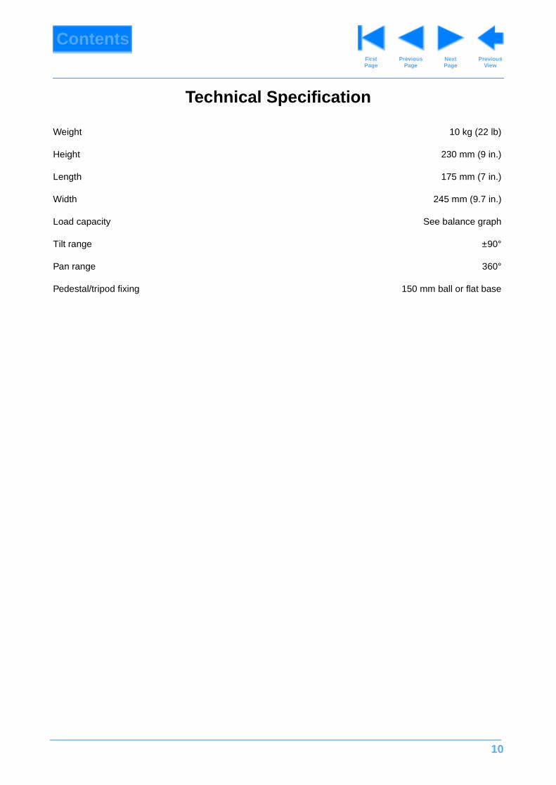
Weight 10 kg (22 lb)
Height 230 mm (9 in.)
Length 175 mm (7 in.)
Width 245 mm (9.7 in.)
Load capacity See balance graph
Tilt range ±90°
Pan range 360°
Pedestal/tripod fixing 150 mm ball or flat base

11
ContentsPrevious
PageFirst Page
Next Page
Previous View
Design Improvements
DETAILSSERIAL No.
INFORMATION
12
ContentsPrevious
PageFirst Page
Next Page
Previous View
Section 1
Introduction and Description
Contents Para
Introduction . . . . . . . . . . . . . . . . . . . . . . . . . . . . . . . . . . . . . . . . . . . . . . . . . . . . . . . . . . . . . . . . . . . . . . . . . . . 1
Description . . . . . . . . . . . . . . . . . . . . . . . . . . . . . . . . . . . . . . . . . . . . . . . . . . . . . . . . . . . . . . . . . . . . . . . . . . . 3
Pan and tilt drag . . . . . . . . . . . . . . . . . . . . . . . . . . . . . . . . . . . . . . . . . . . . . . . . . . . . . . . . . . . . . . . . . . . . . 7
Pan and tilt brakes . . . . . . . . . . . . . . . . . . . . . . . . . . . . . . . . . . . . . . . . . . . . . . . . . . . . . . . . . . . . . . . . . . . 8
Balance . . . . . . . . . . . . . . . . . . . . . . . . . . . . . . . . . . . . . . . . . . . . . . . . . . . . . . . . . . . . . . . . . . . . . . . . . . . 9
Centre lock. . . . . . . . . . . . . . . . . . . . . . . . . . . . . . . . . . . . . . . . . . . . . . . . . . . . . . . . . . . . . . . . . . . . . . . . 10
Pan bar and viewfinder bracket attachment . . . . . . . . . . . . . . . . . . . . . . . . . . . . . . . . . . . . . . . . . . . . . . . 11
Head and camera attachment . . . . . . . . . . . . . . . . . . . . . . . . . . . . . . . . . . . . . . . . . . . . . . . . . . . . . . . . . 12
Introduction
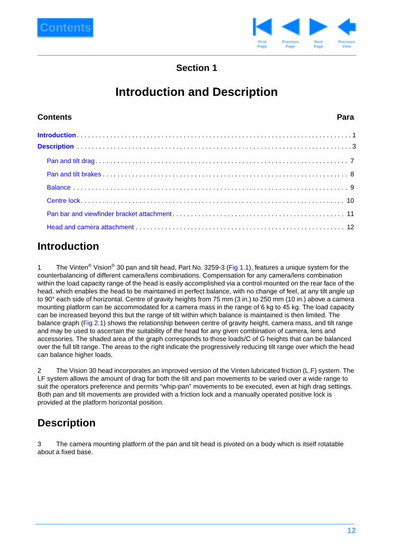
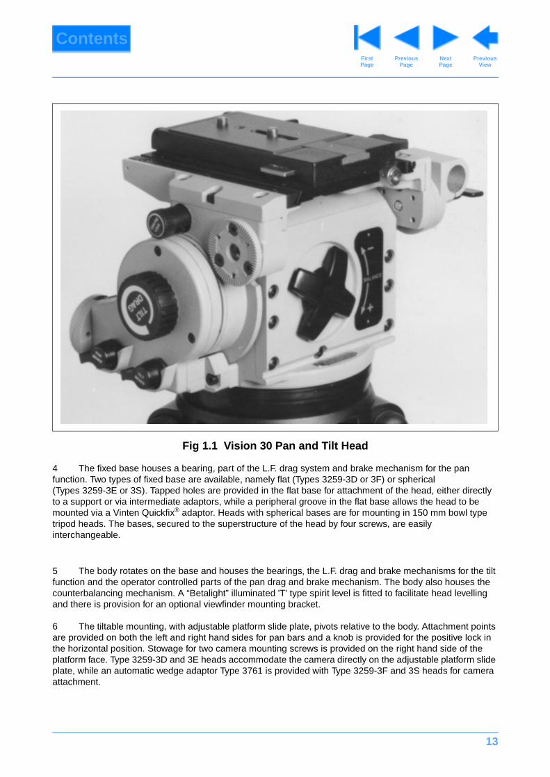
1 The Vinten® Vision® 30 pan and tilt head, Part No. 3259-3 (Fig 1.1), features a unique system for the counterbalancing of different camera/lens combinations. Compensation for any camera/lens combination within the load capacity range of the head is easily accomplished via a control mounted on the rear face of the head, which enables the head to be maintained in perfect balance, with no change of feel, at any tilt angle up to 90° each side of horizontal. Centre of gravity heights from 75 mm (3 in.) to 250 mm (10 in.) above a camera mounting platform can be accommodated for a camera mass in the range of 6 kg to 45 kg. The load capacity can be increased beyond this but the range of tilt within which balance is maintained is then limited. The balance graph (Fig 2.1) shows the relationship between centre of gravity height, camera mass, and tilt range and may be used to ascertain the suitability of the head for any given combination of camera, lens and accessories. The shaded area of the graph corresponds to those loads/C of G heights that can be balanced over the full tilt range. The areas to the right indicate the progressively reducing tilt range over which the head can balance higher loads.
2 The Vision 30 head incorporates an improved version of the Vinten lubricated friction (L.F) system. The LF system allows the amount of drag for both the tilt and pan movements to be varied over a wide range to suit the operators preference and permits “whip-pan” movements to be executed, even at high drag settings. Both pan and tilt movements are provided with a friction lock and a manually operated positive lock is provided at the platform horizontal position.
Description
3 The camera mounting platform of the pan and tilt head is pivoted on a body which is itself rotatable about a fixed base.
13
ContentsPrevious
PageFirst Page
Next Page
Previous View
4 The fixed base houses a bearing, part of the L.F. drag system and brake mechanism for the pan function. Two types of fixed base are available, namely flat (Types 3259-3D or 3F) or spherical (Types 3259-3E or 3S). Tapped holes are provided in the flat base for attachment of the head, either directly to a support or via intermediate adaptors, while a peripheral groove in the flat base allows the head to be mounted via a Vinten Quickfix® adaptor. Heads with spherical bases are for mounting in 150 mm bowl type tripod heads. The bases, secured to the superstructure of the head by four screws, are easily interchangeable.
5 The body rotates on the base and houses the bearings, the L.F. drag and brake mechanisms for the tilt function and the operator controlled parts of the pan drag and brake mechanism. The body also houses the counterbalancing mechanism. A “Betalight” illuminated 'T' type spirit level is fitted to facilitate head levelling and there is provision for an optional viewfinder mounting bracket.
6 The tiltable mounting, with adjustable platform slide plate, pivots relative to the body. Attachment points are provided on both the left and right hand sides for pan bars and a knob is provided for the positive lock in the horizontal position. Stowage for two camera mounting screws is provided on the right hand side of the platform face. Type 3259-3D and 3E heads accommodate the camera directly on the adjustable platform slide plate, while an automatic wedge adaptor Type 3761 is provided with Type 3259-3F and 3S heads for camera attachment.
Fig 1.1 Vision 30 Pan and Tilt Head
14
ContentsPrevious
PageFirst Page
Next Page
Previous View
Pan and tilt drag
7 Both the pan and tilt mechanisms incorporate lubricated friction drag systems to provide smooth movement and jerk-free break-away in the pan and tilt axes. The amount of drag applied is controlled by rotation of large ribbed control knobs, annotated PAN DRAG and TILT DRAG, mounted conveniently on the right and left hand sides of the body respectively.
Pan and tilt brakes
8 Two friction brakes are provided one for the pan and one for tilt movements. The rotary levers, annotated PAN BRAKE and TILT BRAKE, which control these brakes are mounted below the tilt drag control on the left-hand side of the body.
Balance
9 A large cruciform control on the rear of the body is used for adjusting the mechanism which provides the counterbalancing force for a fitted camera. Fine positioning of the camera on the platform, in a fore and aft direction, is accomplished using a lead-screw-driven platform slide. The lead screw is operated via knurled knobs at the front and rear ends of the platform. The amount of adjustment is approximately 50 mm (2 in.). The platform slide is locked in position by two knurled-headed screws on the right hand side of the platform. Scales are provided on the underside of the platform slide for reference and to facilitate re-setting.
Centre lock
10 The position centre lock is controlled by a knob near the top LH side of the head, above the tilt drag control. This lock, retained in the OFF position by a detent, is biased by spring pressure to the engaged position when released. A locking spigot engages an aperture in the side of the head main casting when the platform is at the mid-point of the tilt range. A detent is provided at the disengaged position of the lock to prevent inadvertent engagement. The lock is released by pulling the knob out against the spring pressure and rotating the knob.
Pan bar and viewfinder bracket attachment
11 Quadrant assemblies, each incorporating a tubular clamp, are mountable on each side of the tilting unit to enable pan bars to be attached to the head. The quadrant assemblies provide adjustment for the angle of the pan bars. A third mounting point is provided on the body, facing forward, at the lower left-hand front, for attachment of a viewfinder bracket.
Head and camera attachment
12 The head is mounted on the tripod or pedestal support on which it is to be used via a 150 mm spherical base (Type 3259-3E or 3S heads) or a flat base (Type 3259-3D or 3F heads), which will also accept Quickfix or other mounting adaptors. Spherical bases are secured to the support using a single, central, clamp screw and flat bases are secured using four 3/8 in. hexagon-headed screws.
13 The camera may be attached directly to the platform slide plate via two screws passed through slots in the plate and screwed into the camera base. Alternatively the camera may be attached via a Vinten wedge assembly (Type 3761-13) and automatic wedge adaptor (Type 3761-3).
15
ContentsPrevious
PageFirst Page
Next Page
Previous View
Section 2
Operation
Contents Para
General. . . . . . . . . . . . . . . . . . . . . . . . . . . . . . . . . . . . . . . . . . . . . . . . . . . . . . . . . . . . . . . . . . . . . . . . . . . . . . . 1
Installation
Fitting the head to its support mounting. . . . . . . . . . . . . . . . . . . . . . . . . . . . . . . . . . . . . . . . . . . . . . . . . . . 3
Pan bar attachment . . . . . . . . . . . . . . . . . . . . . . . . . . . . . . . . . . . . . . . . . . . . . . . . . . . . . . . . . . . . . . . . . . 6
Fitting a camera to the head . . . . . . . . . . . . . . . . . . . . . . . . . . . . . . . . . . . . . . . . . . . . . . . . . . . . . . . . . . . 8
Centre screw fixing . . . . . . . . . . . . . . . . . . . . . . . . . . . . . . . . . . . . . . . . . . . . . . . . . . . . . . . . . . . . . . . . 9
Wedge adaptor fixing . . . . . . . . . . . . . . . . . . . . . . . . . . . . . . . . . . . . . . . . . . . . . . . . . . . . . . . . . . . . . 10
Balancing the camera . . . . . . . . . . . . . . . . . . . . . . . . . . . . . . . . . . . . . . . . . . . . . . . . . . . . . . . . . . . . . . . 12
Setting the tilt drag . . . . . . . . . . . . . . . . . . . . . . . . . . . . . . . . . . . . . . . . . . . . . . . . . . . . . . . . . . . . . . . . . . 15
Setting the pan drag. . . . . . . . . . . . . . . . . . . . . . . . . . . . . . . . . . . . . . . . . . . . . . . . . . . . . . . . . . . . . . . . . 16
Setting the pan and tilt brakes . . . . . . . . . . . . . . . . . . . . . . . . . . . . . . . . . . . . . . . . . . . . . . . . . . . . . . . . . 17
Operation . . . . . . . . . . . . . . . . . . . . . . . . . . . . . . . . . . . . . . . . . . . . . . . . . . . . . . . . . . . . . . . . . . . . . . . . . . . . 18
General
1 The Vision 30 Head is part of a range including the Vision 5, 10 and 20 heads. It may be supplied already fitted in a carrying case within a packing case.
2 After removal of the head from its packing ensure that the TILT BRAKE and PAN BRAKE levers are set to the 'ON' position (levers fully clockwise) with the camera mounting platform parallel with the base and the CENTRE LOCK engaged (control knob almost touching side wall of platform). he CENTRE LOCK is provided to retain the platform in a rigid position for fitting and/or removing camera and/or lenses and for safety when a mounted camera is left unattended. The pin of the lock is biased to engage under spring pressure.
WARNING!: Do not rely on the tilt brake mechanism alone during camera mounting/dis-mounting - use the centre lock.
16
ContentsPrevious
PageFirst Page
Next Page
Previous View
Installation
Fitting the head to its support mounting
3 The head may now be mounted to a support (pedestal, tripod, etc.). A flat based head attaches via either
3.1 The four 3/8 in. BSW hex. headed bolts supplied, passed upwards through the support and screwed into the head base. or
3.2 A Vinten Quickfix adaptor, in which case the four 3/8 in. BSW bolts are removed and the head is secured to the adaptor by tightening the three knurled headed screws of the adaptor.
4 A spherical based head attaches to a 150 mm bowl tripod head. The spherical base must be very securely clamped to the support tripod.
5 After attachment to its support the head should be accurately levelled. This is facilitated by using the 'T' type spirit level fitted to the forward end of the tilt drag mechanism cover. The level is illuminated by integral "Betalights" for low light conditions.
Pan bar attachment
6 A quadrant assembly is first loosely attached to the head by its central wingheaded stud.
7 A pan bar is inserted into the clamp ring of the quadrant assembly and the latter is rotated to achieve the required pan bar position. The wingheaded stud is then tightened to retain the pan bar and quadrant assembly in position.
Fitting a camera to the head
8 It is important to ensure that the camera is complete with all its ancillary equipment (lenses, zoom and focus controls, etc) otherwise the later balancing #!of the system will be upset.
Centre screw fixing
9 Ensure a camera mounting screw is located in the required slot in the platform slide plate. It may be repositioned by withdrawing it from the underside of the platform slide plate and inserting in the other slot. Access to the slots is gained by repositioning the platform slide plate. It is possible that a second screw may be required if the camera/lens combination is mounted via a sub-plate. The screws are housed, when not in use, in tapped holes in the rear right hand side of the platform casting. Recheck that the CENTRE LOCK is
WARNING!: Do not tighten wingheaded stud if a pan bar is not fitted.
WARNING!: The centre lock and the pan and tilt brakes must be applied before any attempt is made to fit or remove any equipment mounted on the pan and tilt head.
17
ContentsPrevious
PageFirst Page
Next Page
Previous View
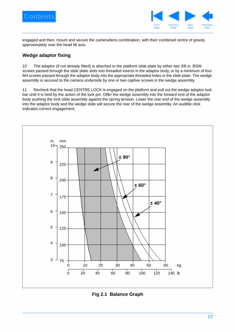
engaged and then, mount and secure the camera/lens combination, with their combined centre of gravity approximately over the head tilt axis.
Wedge adaptor fixing
10 The adaptor (if not already fitted) is attached to the platform slide plate by either two 3/8 in. BSW screws passed through the slide plate slots into threaded inserts in the adaptor body, or by a minimum of four M4 screws passed through the adaptor body into the appropriate threaded holes in the slide plate. The wedge assembly is secured to the camera underside by one or two captive screws in the wedge assembly.
11 Recheck that the head CENTRE LOCK is engaged on the platform and pull out the wedge adaptor lock bar until it is held by the action of the lock pin. Offer the wedge assembly into the forward end of the adaptor body pushing the lock slide assembly against the spring tension. Lower the rear end of the wedge assembly into the adaptor body and the wedge slide will secure the rear of the wedge assembly. An audible click indicates correct engagement.
Fig 2.1 Balance Graph
75
100
125
175
200
225
0 10 20 30 40 50 kg
150
250
60
0 20 40 60 80 100 120 lb
3
4
5
6
7
8
9
10mmin.
140
± 90°
± 40°
± 60°
18
ContentsPrevious
PageFirst Page
Next Page
Previous View
Balancing the camera
12 Balancing the Vision 30 head achieves two objectives. Firstly, when a head is correctly balanced the operator will need a minimum amount of even effort to move the head. Secondly, once balanced, the head and its payload can be set to any tilt position and the head will maintain this position with “hands off”.
13 The graph (Fig 2.1) illustrates the relationship between load and centre-of-gravity (C of G) height and may be used to ascertain the suitability of the head for any given combination of camera, lens and accessories. The shaded area of the graph corresponds to those loads/C of G heights that can be balanced over the full tilt range. The areas to the right indicate the progressively reducing tilt range over which the head can balance higher loads.
14 Ensure the pan bar or bars with zoom and focus controls are fitted to the platform, that the platform is horizontal and proceed as follows:
14.1 Turn the balance adjustment knob approximately 15 to 20 revolutions in the positive (+) (clockwise) direction.
14.2 Position the centre of gravity of the camera/lens combination over the head tilt axis by adjusting the platform slide. Slacken two slide lock screws protruding from the right hand side plate and by operation of either slide adjuster knob, positioned one at each end of the platform slide, position the slide and camera/lens combination to give equal 'fall-away' or 'centring' tendency in both directions. Relock slide in position using the two slide lock screws.
14.3 Hold the pan bar to restrain possible movement about the tilt axis and release the CENTRE LOCK (pull out and turn) and the TILT BRAKE (lever fully counter-clockwise).
14.4 By feel on the pan bar determine whether the platform 'centres' or tends to 'fall away' forwards or backwards.
14.4.1 If the platform 'centres' decrease balance by turning the adjustment knob counter-clockwise until an approximate balance is achieved.
14.4.2 If the platform tends to 'fall-away' in either direction increase balance by turning the adjustment knob clockwise until an approximate balance is achieved.
14.5 Finely trim the balance and fore and aft adjustments to achieve accurate balance throughout the full tilt range.
14.6 Re-engage CENTRE LOCK and apply TILT BRAKE.
Setting the tilt drag
15 Hold the pan bar and release the CENTRE LOCK and TILT BRAKE. Turn the TILT DRAG control knob, on the left hand side, to the required amount of drag; clockwise to increase, counter-clockwise to decrease.
Setting the pan drag
16 The pan drag is set in a similar manner to the tilt drag by operation of the PAN DRAG control knob on the right hand side of the head.
19
ContentsPrevious
PageFirst Page
Next Page
Previous View
Setting the pan and tilt brakes
17 Both the PAN BRAKE and TILT BRAKE are fully applied when the respective lever on the left hand side of the head is rotated fully clockwise.
Operation
18 With the PAN BRAKE, TILT BRAKE applied and the CENTRE LOCK engaged, adjust the position of the pan bar to suit the operators requirements by slackening the wing headed stud and moving the pan bar and quadrant to the desired position. Retighten the wing headed stud.
19 While firmly holding the pan bar withdraw the tilt CENTRE LOCK control knob and set the PAN BRAKE and TILT BRAKE to the off position.
20 Check the freedom of movement in both pan and tilt axes and adjust the drag on each by means of the PAN DRAG and TILT DRAG control knobs to suit, the operator.
21 The PAN BRAKE and TILT BRAKE must be applied if the camera is to be left on a static shot for any period of time with the operator in control to prevent inadvertent movement.
22 If the camera is to be left unattended the PAN BRAKE and TILT BRAKE must be applied and the tilt CENTRE LOCK engaged.
WARNING!: The tilt centre lock must be engaged and the pan and tilt brakes must be applied before any attempt is made to fit or remove any equipment mounted on the pan and tilt head.
NOTE: Repositioning of the pan bars may necessitate fine adjustment in the fore and aft position of the camera and of the balance.
20
ContentsPrevious
PageFirst Page
Next Page
Previous View
Section 3
Tools and Materials
Special tools
1 No special tools are required
Consumable materials
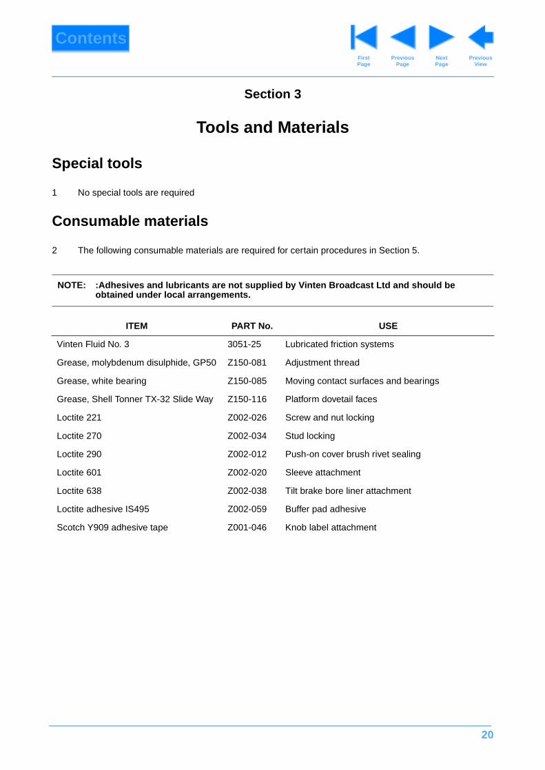
2 The following consumable materials are required for certain procedures in Section 5.
NOTE: :Adhesives and lubricants are not supplied by Vinten Broadcast Ltd and should be obtained under local arrangements.
ITEM PART No. USE
Vinten Fluid No. 3 3051-25 Lubricated friction systems
Grease, molybdenum disulphide, GP50 Z150-081 Adjustment thread
Grease, white bearing Z150-085 Moving contact surfaces and bearings
Grease, Shell Tonner TX-32 Slide Way Z150-116 Platform dovetail faces
Loctite 221 Z002-026 Screw and nut locking
Loctite 270 Z002-034 Stud locking
Loctite 290 Z002-012 Push-on cover brush rivet sealing
Loctite 601 Z002-020 Sleeve attachment
Loctite 638 Z002-038 Tilt brake bore liner attachment
Loctite adhesive IS495 Z002-059 Buffer pad adhesive
Scotch Y909 adhesive tape Z001-046 Knob label attachment
21
ContentsPrevious
PageFirst Page
Next Page
Previous View
Section 4
Servicing
Contents Para
General. . . . . . . . . . . . . . . . . . . . . . . . . . . . . . . . . . . . . . . . . . . . . . . . . . . . . . . . . . . . . . . . . . . . . . . . . . . . . . . 1
Cleaning . . . . . . . . . . . . . . . . . . . . . . . . . . . . . . . . . . . . . . . . . . . . . . . . . . . . . . . . . . . . . . . . . . . . . . . . . . . . . . 2
Lubrication. . . . . . . . . . . . . . . . . . . . . . . . . . . . . . . . . . . . . . . . . . . . . . . . . . . . . . . . . . . . . . . . . . . . . . . . . . . . 4
Brake adjustment . . . . . . . . . . . . . . . . . . . . . . . . . . . . . . . . . . . . . . . . . . . . . . . . . . . . . . . . . . . . . . . . . . . . . . 6
General
1 The Vision 30 pan and tilt head is robustly made to high engineering standards and little attention is required to maintain serviceability save regular cleaning. Attention to the following points will ensure a long and useful life with minimum need for repair.
Cleaning
2 During indoor use, the only cleaning required should be a regular wipe over with a lint-free cloth. Dirt accumulated during storage may be removed using a semi-stiff brush. Particular attention should be paid to the levelling bowl and mounting face of the head and to the space between the tilting assembly and the base.
3 All Vision heads are weatherproof. However, use out-of-doors under adverse conditions will require special attention. Salt spray should be washed off with fresh water at the earliest opportunity. Sand and dirt acts as an abrasive and should be removed using a semi-stiff brush or vacuum cleaner
Lubrication
4 The roller and thrust bearings contained in the pan and tilt head are packed with grease prior to final assembly and should not require re-greasing, in normal working use, for several years. The bearings are either totally enclosed within the head or fitted with adequate protection.
5 With both the pan and tilt drag controls rotated fully counter-clockwise, both brake controls rotated fully counter-clockwise and the CENTRE LOCK disengaged both pan and tilt rotation should have complete freedom of movement. Should stiffness in movement of these units occur then re-greasing of the bearings will be necessary.
Brake adjustment
6 The pan and tilt brake knobs are set during manufacture so that the brakes are fully applied when the knobs are in the vertical position. As the brakes bed in during use it may be necessary to reset the knobs.
NOTE: Use only detergent-based cleaners. DO NOT use solvent- or oil-based cleaners, abrasives or wire brushes to remove accumulations of dirt, as these damage the protective surfaces.

22
ContentsPrevious
PageFirst Page
Next Page
Previous View
7 The procedure for resetting the pan and tilt brake knobs is as follows:
7.1 Apply the brakes.
7.2 Referring to Fig 6.2, remove the grubscrew (54) and pull the knob (53) off the shaft. Ensure knob retainer (53A) remains on shaft.
7.3 Turn the shaft so that the brake is fully applied and refit knob (53) in the vertical position. Secure with grubscrew (54), ensure grubscrew seats correctly in knob retainer (53A).
23
ContentsPrevious
PageFirst Page
Next Page
Previous View
Section 5
Repair
Contents Para
Repair . . . . . . . . . . . . . . . . . . . . . . . . . . . . . . . . . . . . . . . . . . . . . . . . . . . . . . . . . . . . . . . . . . . . . . . . . . . . . . . 25
Section 5 - Repair
Repair . . . . . . . . . . . . . . . . . . . . . . . . . . . . . . . . . . . . . . . . . . . . . . . . . . . . . . . . . . . . . . . . . . . . . . . . . . . 26
Repair
Platform assembly . . . . . . . . . . . . . . . . . . . . . . . . . . . . . . . . . . . . . . . . . . . . . . . . . . . . . . . . . . . . . . . 26
Platform assembly . . . . . . . . . . . . . . . . . . . . . . . . . . . . . . . . . . . . . . . . . . . . . . . . . . . . . . . . . . . . . . . 26
Platform assembly . . . . . . . . . . . . . . . . . . . . . . . . . . . . . . . . . . . . . . . . . . . . . . . . . . . . . . . . . . . . . . . 27
Platform assembly . . . . . . . . . . . . . . . . . . . . . . . . . . . . . . . . . . . . . . . . . . . . . . . . . . . . . . . . . . . . . . . 27
Platform assembly . . . . . . . . . . . . . . . . . . . . . . . . . . . . . . . . . . . . . . . . . . . . . . . . . . . . . . . . . . . . . . . 27
Repair
Top cover . . . . . . . . . . . . . . . . . . . . . . . . . . . . . . . . . . . . . . . . . . . . . . . . . . . . . . . . . . . . . . . . . . . . . . 27
Top cover . . . . . . . . . . . . . . . . . . . . . . . . . . . . . . . . . . . . . . . . . . . . . . . . . . . . . . . . . . . . . . . . . . . . . . 28
Repair
Front cover . . . . . . . . . . . . . . . . . . . . . . . . . . . . . . . . . . . . . . . . . . . . . . . . . . . . . . . . . . . . . . . . . . . . . 28
Front cover . . . . . . . . . . . . . . . . . . . . . . . . . . . . . . . . . . . . . . . . . . . . . . . . . . . . . . . . . . . . . . . . . . . . . 28
Repair
End plate/adjustment thread assembly. . . . . . . . . . . . . . . . . . . . . . . . . . . . . . . . . . . . . . . . . . . . . . . . 28
End plate/adjustment thread assembly. . . . . . . . . . . . . . . . . . . . . . . . . . . . . . . . . . . . . . . . . . . . . . . . 29
Repair
Cross members. . . . . . . . . . . . . . . . . . . . . . . . . . . . . . . . . . . . . . . . . . . . . . . . . . . . . . . . . . . . . . . . . . 29
Cross members. . . . . . . . . . . . . . . . . . . . . . . . . . . . . . . . . . . . . . . . . . . . . . . . . . . . . . . . . . . . . . . . . . 29
Cross members. . . . . . . . . . . . . . . . . . . . . . . . . . . . . . . . . . . . . . . . . . . . . . . . . . . . . . . . . . . . . . . . . . 30
Cross members. . . . . . . . . . . . . . . . . . . . . . . . . . . . . . . . . . . . . . . . . . . . . . . . . . . . . . . . . . . . . . . . . . 30
Repair
Mechanism block and secondary spring assemblies . . . . . . . . . . . . . . . . . . . . . . . . . . . . . . . . . . . . . 31

24
ContentsPrevious
PageFirst Page
Next Page
Previous View
Mechanism block and secondary spring assemblies . . . . . . . . . . . . . . . . . . . . . . . . . . . . . . . . . . . . . 31
Mechanism block and secondary spring assemblies . . . . . . . . . . . . . . . . . . . . . . . . . . . . . . . . . . . . . 32
Mechanism block and secondary spring assemblies . . . . . . . . . . . . . . . . . . . . . . . . . . . . . . . . . . . . . 32
Mechanism block and secondary spring assemblies . . . . . . . . . . . . . . . . . . . . . . . . . . . . . . . . . . . . . 32
Repair
Pan drag unit assembly. . . . . . . . . . . . . . . . . . . . . . . . . . . . . . . . . . . . . . . . . . . . . . . . . . . . . . . . . . . . 34
Pan drag unit assembly. . . . . . . . . . . . . . . . . . . . . . . . . . . . . . . . . . . . . . . . . . . . . . . . . . . . . . . . . . . . 34
Pan drag unit assembly. . . . . . . . . . . . . . . . . . . . . . . . . . . . . . . . . . . . . . . . . . . . . . . . . . . . . . . . . . . . 35
Pan drag unit assembly. . . . . . . . . . . . . . . . . . . . . . . . . . . . . . . . . . . . . . . . . . . . . . . . . . . . . . . . . . . . 36
Repair
Loading bars . . . . . . . . . . . . . . . . . . . . . . . . . . . . . . . . . . . . . . . . . . . . . . . . . . . . . . . . . . . . . . . . . . . . 37
Loading bars . . . . . . . . . . . . . . . . . . . . . . . . . . . . . . . . . . . . . . . . . . . . . . . . . . . . . . . . . . . . . . . . . . . . 38
Loading bars . . . . . . . . . . . . . . . . . . . . . . . . . . . . . . . . . . . . . . . . . . . . . . . . . . . . . . . . . . . . . . . . . . . . 38
Loading bars . . . . . . . . . . . . . . . . . . . . . . . . . . . . . . . . . . . . . . . . . . . . . . . . . . . . . . . . . . . . . . . . . . . . 39
Repair
Side plate assembly . . . . . . . . . . . . . . . . . . . . . . . . . . . . . . . . . . . . . . . . . . . . . . . . . . . . . . . . . . . . . . 39
Side plate assembly . . . . . . . . . . . . . . . . . . . . . . . . . . . . . . . . . . . . . . . . . . . . . . . . . . . . . . . . . . . . . . 39
Side plate assembly . . . . . . . . . . . . . . . . . . . . . . . . . . . . . . . . . . . . . . . . . . . . . . . . . . . . . . . . . . . . . . 39
Repair . . . . . . . . . . . . . . . . . . . . . . . . . . . . . . . . . . . . . . . . . . . . . . . . . . . . . . . . . . . . . . . . . . . . . . . . . . . 40
Tilt drag unit assembly . . . . . . . . . . . . . . . . . . . . . . . . . . . . . . . . . . . . . . . . . . . . . . . . . . . . . . . . . . . . 40
Tilt drag unit assembly . . . . . . . . . . . . . . . . . . . . . . . . . . . . . . . . . . . . . . . . . . . . . . . . . . . . . . . . . . . . 41
Tilt drag unit assembly . . . . . . . . . . . . . . . . . . . . . . . . . . . . . . . . . . . . . . . . . . . . . . . . . . . . . . . . . . . . 41
Tilt drag unit assembly . . . . . . . . . . . . . . . . . . . . . . . . . . . . . . . . . . . . . . . . . . . . . . . . . . . . . . . . . . . . 42
Repair
Other components . . . . . . . . . . . . . . . . . . . . . . . . . . . . . . . . . . . . . . . . . . . . . . . . . . . . . . . . . . . . . . . 43
Lower carriage roller
Remove . . . . . . . . . . . . . . . . . . . . . . . . . . . . . . . . . . . . . . . . . . . . . . . . . . . . . . . . . . . . . . . . . . . . . 63
Refit . . . . . . . . . . . . . . . . . . . . . . . . . . . . . . . . . . . . . . . . . . . . . . . . . . . . . . . . . . . . . . . . . . . . . . . . 64
25
ContentsPrevious
PageFirst Page
Next Page
Previous View
Guide roller track blocks
Remove . . . . . . . . . . . . . . . . . . . . . . . . . . . . . . . . . . . . . . . . . . . . . . . . . . . . . . . . . . . . . . . . . . . . . 65
Refit . . . . . . . . . . . . . . . . . . . . . . . . . . . . . . . . . . . . . . . . . . . . . . . . . . . . . . . . . . . . . . . . . . . . . . . . 66
Pan drag actuator shaft and lever
Remove . . . . . . . . . . . . . . . . . . . . . . . . . . . . . . . . . . . . . . . . . . . . . . . . . . . . . . . . . . . . . . . . . . . . . 67
Refit . . . . . . . . . . . . . . . . . . . . . . . . . . . . . . . . . . . . . . . . . . . . . . . . . . . . . . . . . . . . . . . . . . . . . . . . 69
Pan brake actuator shaft
Remove . . . . . . . . . . . . . . . . . . . . . . . . . . . . . . . . . . . . . . . . . . . . . . . . . . . . . . . . . . . . . . . . . . . . . 70
Refit . . . . . . . . . . . . . . . . . . . . . . . . . . . . . . . . . . . . . . . . . . . . . . . . . . . . . . . . . . . . . . . . . . . . . . . . 71
General
1 Repair and renewal of damaged items involves disassembling various assemblies and must be carried out in accordance with the following instructions. Any load must be removed from the pedestal before carrying out the following procedures.
2 Disassembly and assembly of the various components is carried out in conjunction with figures in the Illustrated Parts List (Section 6).
3 The Vision 30 pan and tilt head may be divided into a number of separate assemblies to facilitate repair. In use the head will have various accessories, zoom and focus controls viewfinders etc., which must be removed before dismantling the basic head. The pan bar and quadrant assemblies may be removed, for convenience, prior to performing repairs to the head. The base assembly affords protection to the pan drag unit and is removed prior to repair to this assembly or to the pan brake assembly. The automatic wedge adaptor assembly, if fitted, (Type 3259-3F and 3S heads) may remain attached to the platform assembly unless repairs to the platform are required.
4 The basic unit comprises the secondary mechanism which has the following main components/assemblies.
4.1 The mechanism block assembly and associated secondary spring assembly.
4.2 The adjustment thread assembly.
4.3 The two cross members.
4.4 The pan drag lubricated friction mechanism.
4.5 The pan brake mechanism.
4.6 The platform on which the camera equipment is mounted.
NOTE: Certain special consumable materials are required for procedures detailed in this Section. Please refer to Section 3 - Tools and Materials. For further details, please contact Vinten Broadcast Ltd or your local distributor.

26
ContentsPrevious
PageFirst Page
Next Page
Previous View
4.7 The primary mechanism assembly.
5 The primary mechanism assembly consists of the following main components/assemblies.
5.1 The main casting with associated parts.
5.2 The loading bars which operate in conjunction with the mechanism block assembly.
5.3 The tilt drag lubricated friction mechanism.
5.4 The tilt brake mechanism.
5.5 The side plate which supports the right had side of the platform.
5.6 The bearing bracket and associated parts.
6 To remove any part of the primary mechanism assembly it is first necessary to remove the items of the secondary mechanism assembly as detailed in Para 9, Para 14, 1Para 16, Para 18, Para 20 and Para 24. The items of the secondary mechanism assembly are refitted as detailed in Para 30, Para 23, Para 19, Para 17, Para 15 and Para 13.
Repair
Pan bar and quadrant assembly
7 The pan bar assembly (Fig 6.11 item 248) is secured in the quadrant assembly (Fig 6.10 item 241) by a screw and washer (Fig 6.1). To remove the pan bar, unscrew the quadrant wing nut (243).
8 The quadrant assembly (241) is refitted by positioning it on a serrated plate (109) and securing with the wing nut (243).
Platform assembly
Remove
9 The platform assembly (38) is removed as follows (Fig 6.2 and Fig 6.8):
9.1 Unscrew and remove two slide clamps screws (58).
9.2 Unscrew and remove three M6 socket cap head screws (39) recessed in left hand upper face.
9.3 Unscrew and remove four M6 button head screws (31) from right hand side plate (82).
9.4 Remove platform assembly (38).
Automatic wedge adaptor assembly
10 The automatic wedge adaptor assembly (281) is removed as follows (Fig 6.14):
10.1 Unscrew and remove six M4 pan head screws (Fig 6.1 item H) or unscrew two 3/8 BSW screws (219) (shown stowed on Fig 6.8) whichever is applicable
10.2 Remove the assembly.
27
ContentsPrevious
PageFirst Page
Next Page
Previous View
10.3 The adaptor assembly is refitted by a reversal of this procedure.
Dismantle
11 To dismantle the platform assembly (Fig 6.8),proceed as follows
11.1 Unscrew and remove two M3 pan head screws (129) and slide out gib strip (218).
11.2 Tap out spirol pin (212) from one slide adjuster knob (211) and remove knob with its shim (159).
11.3 By turning remaining knob withdraw the slide adjuster stud (209) from threaded block (207).
11.4 Further dismantling of the platform will be obvious on inspection.
Assemble
12 Reassembly of the platform assembly is performed by a reversal of the procedure detailed at Para 11 noting the following points.
12.1 Dovetail faces should be lightly lubricated with Shell Tonner TX-32 grease.
12.2 The remaining moving contact surfaces should be lightly lubricated with white bearing grease.
12.3 The 'T' on threaded block (207) must be on visible face.
12.4 The gib strip (218) is lightly retained by the M3 screws.
12.5 Screws securing threaded block (207), platform slide block (210) and gib strip (218) are locked using Loctite 221 on the threads.
12.6 Dovetail insert (215) should be adjusted to ensure an easy sliding action with minimum clearance.
Refit
13 The platform assembly is refitted by a reversal of the procedure detailed at Para 9.
Top cover
Remove
14 The top cover (37) is removed as follows (Fig 6.2):
14.1 Remove platform as detailed in Para 9.
14.2 Unscrew and remove four M4 socket cap head screws (33).
14.3 Remove top cover (37)
28
ContentsPrevious
PageFirst Page
Next Page
Previous View
Refit
15 The top cover is refitted by a reversal of the procedure detailed at Para 14, ensuring the left-hand end is flush with the main casting (61) (Fig 6.3).
Front cover
Remove
16 The front cover (32) is removed as follows (Fig 6.2):
16.1 Remove top cover as detailed in Para 14.
16.2 Unscrew and remove four M4 socket cap head screws (33).
16.3 Remove front cover (32).
Refit
17 The front cover is refitted by a reversal of the procedure detailed at Para 16, ensuring the left-hand end is flush with the main casting (61) (Fig 6.3).
End plate/adjustment thread assembly
Remove
18 The end plate/adjustment thread assembly (29) is removed as follows (Fig 6.7 and Fig 6.2):
18.1 Position tilt assembly horizontally and engage CENTRE LOCK.
18.2 Rotate BALANCE adjustment knob (186) fully counter-clockwise.
18.3 Unscrew and remove single M6 button head screw (31) below adjustment knob (186).
18.4 Unscrew and remove six M6 button head screws (30), three from each side of adjustment knob (186).
18.5 Withdraw end plate/adjustment thread assembly (29) from main casting (61) (Fig 6.3).
18.6 Withdraw main spring (28) from within mechanism block assembly (12).
WARNING!: There is risk of serious injury if any attempt is made to remove the end plate/adjustment thread assembly while the main spring is compressed, i.e. when the platform is tilted or when adjustment knob is not turned fully counter-clockwise.
NOTE: Complete dismantling of the assembly is not recommended. Should the needle thrust bearing (193) require regreasing this can be accomplished with the bearing in situ after screwing the main spring adjustment shaft (191) out of the adjustment nut (201). If it becomes necessary to remove bearing (193) a procedure for its removal is detailed at Para 61.
29
ContentsPrevious
PageFirst Page
Next Page
Previous View
Refit
19 The end plate/adjustment thread assembly is refitted as follows (Fig 6.7 and Fig 6.2):
19.1 Insert main spring (28) into mechanism block (12).
19.2 Grease thread of main spring adjustment shaft (191) with molybdenum disulphide grease GP50.
19.3 Ensure adjustment nut (201) assembled to collar (197) is screwed up to thrust race (192) on end bracket (195) by turning adjustment knob (186) fully counter-clockwise.
19.4 Insert main spring adjustment shaft (191) into mechanism block (12) ensuring plain end of shaft (191) is inserted in the mechanism blocks adjustment shaft bearing (169) (Fig 6.6) and that the guide roller bearing (199) engages in the lower trackway in the primary mechanism assembly.
19.5 Secure end bracket (195) to main casting (61) with six M6 button head screws (30) removed at Para 18.4 and one M6 button head screw (31) removed at Para 18.3.
19.6 Turn adjustment knob (186) clockwise two or three turns to apply light pressure to main spring (28).
19.7 If mechanism block assembly (12) has not been disturbed slacken four M5 button head screws (14) securing load beam (174) (Fig 6.6).
19.8 Checking that loading bar assemblies (119) and (130) are positioned vertically and that secondary spring (176) (Fig 6.6) is centrally located in its bore in balance mechanism block (166), tighten load beam securing screws (14).
Cross members
Remove
20 The procedure for both front and rear cross members (15 and 21 respectively) is similar except that the rear cross member is fitted with two additional rollers. The procedure is as follows (Fig 6.2):
20.1 Remove platform assembly as detailed at Para 9.
20.2 Remove top cover as detailed at Para 14.
20.3 Remove front cover as detailed at Para 16.
20.4 Remove end plate/adjustment thread assembly and main spring as detailed at Para 18.
20.5 Unscrew and remove M4 button head screw (16) from each end of cross member (15) or (21) - front or rear respectively.
20.6 Lift cross member (15) or (21) from its locating pins (93) (Fig 6.3).
Dismantle
21 To dismantle the cross member continue as follows (Fig 6.2):
21.1 For each yoke type track roller (17):
30
ContentsPrevious
PageFirst Page
Next Page
Previous View
21.1.1 Slacken M3 socket head grubscrew (20) securing axle-cross member roller (19).
21.1.2 Press out axle (19) and remove track roller (17) and its associated shims (18).
21.2 For each lateral guide roller (22) on rear cross member (21):
21.2.1 Unscrew and remove M4 button head screw (24).
21.2.2 Remove bush (23) complete with its lateral guide roller (22).
Assemble
22 The cross members are assembled as follows (Fig 6.2):
22.1 For each lateral guide roller (22) on rear cross member (21):
22.1.1 Assemble lateral guide roller (22) to its bush (23).
22.1.2 Assembly bush (23) and roller (22) to cross member (21) using M4 button head screw (24) removed at Para 21.2.1. Do not fully tighten screw at this stage.
22.2 For each yoke type track roller (17):
22.2.1 Apply white bearing grease to track roller (17) and faces of shims.
22.2.2 Assemble track roller (17) with one shim (18) on each side face into cross member and retain with an axle (19) removed at Para 21.1.2. Ensure M3 socket head grub screw (20) is seated on flat of axle and that axle is flush with inner face of cross member.
22.2.3 Tighten M3 socket head grub screw (20) to retain axle (19).
Refit
23 To refit the cross members continue as follows (Fig 6.2):
23.1 Apply white bearing grease to cross member locating pins (93).
23.2 Very sparingly apply Loctite 221 into tapped hole of locating pins (93).
23.3 Position each cross member on its respective locating pins (93).
23.4 Insert M4 button head screws (16) and evenly adjust both ends of each cross member so that yoke type track rollers (17) just contact mechanism block tracks (168) (Fig 6.6) with no pre-load. Check no clearance exists between any horizontal track and associated roller (8 positions).
23.5 Adjust lateral position of mechanism block assembly (12) to equalize clearance between block (166) should be central with guide roller tracks (90) (Fig 6.3) on inner surface of main casting (61).
23.6 Tighten lateral guide roller screws (24) on rear cross member (21) so that there is no clearance between rollers and their tracks on mechanism block (166). Do not pre-load.
NOTE: The lateral guide rollers (22) on the rear cross member (21) locate between the two vertical tracks machined into the rear of the mechanism block assembly (12).
31
ContentsPrevious
PageFirst Page
Next Page
Previous View
Mechanism block and secondary spring assemblies
Remove
24 The mechanism block assembly (12) is removed as follows (Fig 6.6):
24.1 Remove platform assembly as detailed at Para 9.
24.2 Remove top cover as detailed at Para 14.
24.3 Remove front cover as detailed atPara 16.
24.4 Remove end plate/adjustment thread assembly and main spring as detailed at Para 18.
24.5 Remove cross members as detailed at Para 20.5 and Para 20.6.
24.6 Unscrew and remove two M5 button head screws (14) from each end of load beam (174).
24.7 Remove two spring plugs (27), springs (26) and plunger-carriage assembly (25) from mechanism block (Fig 6.2)
24.8 Lift out mechanism block assembly (12).
24.9 Retain shims (13) from tops of loading bars (119) and (130) noting their orientation for replacement.
Dismantle
25 To dismantle the mechanism block assembly (12) continue as follows (Fig 6.6):
25.1 Unscrew and remove secondary spring adjustment plug (181) and inspect buffer pad-lower end (182) for deterioration.
25.2 Unscrew and remove two M4 socket countersunk head screws (179) securing first stop plate-secondary spring (178). Remove stop plate and inspect buffer pad-stop plate (180) for deterioration.
25.3 Repeat Para 25.2 for second stop plate-secondary spring.
25.4 Lift out secondary spring assembly (171).
25.5 Inspect rubber buffer-spring carriage (170) for deterioration.
25.6 Inspect vertical and horizontal track faces for scoring.
26 To dismantle the secondary spring assembly (171) continue as follows:
26.1 Remove spring guide-lower (177) and remove spring (176).
26.2 Withdraw screw (172) and separate guide-top (175) and load beam (174).
26.3 Degrease screw shank and spring guide-top.
26.4 Inspect buffer pads (173), on underside of screw (172) head and underside of load beam (174), for deterioration.
32
ContentsPrevious
PageFirst Page
Next Page
Previous View
Buffer pad renewal
27 In the event that any of the buffer pads on the mechanism block assembly or the secondary spring assembly have deteriorated they should be replaced. Remove all traces of the defective pad and adhesive, ensure both pad and component are free from greasy deposits (use IS Quick Clean) and secure new pads with Loctite adhesive IS495. Ensure the following conditions are achieved:
27.1 Stop plate-secondary spring (178) pad must be flush with inner edge of stop plate.
27.2 Buffer pad-lower end (182) on adjustment plug (181), rubber buffer-spring carriage (170), buffer pad on load beam (174) and buffer pad on screw (172) must be positioned concentrically.
27.3 Ensure sound joint is made.
Assemble
28 The secondary spring assembly is assembled as follows (Fig 6.6):
28.1 Lightly apply white bearing grease to shank of screw (172). Avoid applying grease to thread.
28.2 Pass screw (172) shank through load beam (174) and spring guide top (175).
28.3 Fit spring (176) over screw (172) shank and tubular part of spring guide-top (175).
28.4 Screw on spring guide-lower (177) a few turns and then sparingly apply Loctite 221 to screw thread in free end of spring guide-lower (177). Continue to tighten and adjust until all axial movement of components is removed without causing any pre-load to spring. This adjustment is critical.
29 The mechanism block assembly is assembled as follows:
29.1 Ensure adjustment shaft bearing (169) is flush with balance mechanism block (166) end face.
29.2 Assemble secondary spring assembly (171) into balance mechanism block (166).
29.3 Retain secondary spring assembly (171) with stop plates-secondary spring (178) and M4 screws (179) removed at Para 26, ensuring rubber buffers orientated correctly. Lock screws with Loctite 221. Ensure buffer pads-stop plate (180) are not pinched between stop plate (178) and balance mechanism block (166).
29.4 Fit adjustment plug (181) and adjust until all axial clearance of components has been removed without causing any pre-load to spring (176). This adjustment is critical. Secure adjustment plug (181) with Titanine.
Refit
30 The mechanism block assembly is refitted as follows (Fig 6.6):
30.1 Position mechanism block assembly (12) on lower guide rollers (17) (Fig 6.3) in primary mechanism (2) ensuring that loading bars (119) and (130) are correctly orientated and engaged with load beam (174).
30.2 Apply downward pressure to mechanism block assembly (12) and ensure block sits squarely on all four rollers (17) with no perceptible rock. If block does not sit squarely proceed as follows:
30.2.1 Slacken locking screw (5) (Fig 6.3) at right rear axle position.
33
ContentsPrevious
PageFirst Page
Next Page
Previous View
30.2.2 Adjust adjustable axle (87) (Fig 6.3) until block ceases to rock.
30.2.3 Tighten locking screw (5) and recheck block for stability.
30.2.4 Repeat Para 30.2.1 to Para 30.2.3 if necessary.
30.3 Refit two plunger (carriage assemblies) (25), springs (26) and spring plugs (27) removed at Para 24.7. Ensure ends of spring plugs (27) are flush with front face of balance mechanism block (166).
30.4 Continue refitting procedure at Para 31 or Para 32 as appropriate.
31 If it has been necessary to change any of the buffer pads proceed as follows:
31.1 Temporarily attach platform assembly (38) by a reversal of procedure at Para 9.2 to Para 9.4.
31.2 Using two sets of feeler gauges measure clearance between loading bars (119) and (130) and load beam (174) and note dimensions, which should be approximately equal. Care must be exercised to ensure no bias is put onto loading bars during this operation.
31.3 Remove platform assembly as detailed at Para 9.2 to Para 9.4.
31.4 Peel laminations from new load beam shims (13) (Fig 6.2) to achieve dimensions noted atPara 31.2.
31.5 Assemble shims into position and retain each with two M5 button head screws (14) passed through load beam into respective loading bar. Do not tighten screws at this stage. Final tightening is performed during refitting of end plate/adjustment shaft assembly.
31.6 Continue refitting at Para 33.
32 If no buffer pads have been changed proceed as follows:
32.1 Refit shims removed at Para 24.9, ensuring same orientation as removed.
32.2 Retain shims with two M5 button head screws (14) passed through load beam into each loading bar. Do not tighten screws at this stage. Final tightening is performed during refitting of end plate/adjustment thread assembly.
33 Continue the mechanism block assembly refitting as follows:
33.1 Refit cross members as detailed at Para 23.
33.2 Refit main spring and end plate/adjustment thread assembly as detailed at Para 19.
33.3 Refit front cover as detailed at Para 17.
33.4 Refit top cover as detailed atPara 15.
33.5 Refit platform assembly as detailed at Para 13.
Base assembly
34 The base assembly (either spherical (266, Fig 6.12) or flat (276,Fig 6.13) is removed by unscrewing and removing the four M5 socket cap head screws (Fig 6.1 item D) and lifting the head from the base. The base is refitted by a reversal of this procedure.

34
ContentsPrevious
PageFirst Page
Next Page
Previous View
Pan drag unit assembly
Remove
35 The pan drag unit assembly (3) is removed as follows (Fig 6.2):
35.1 Align two notches in periphery of pan drag unit assembly (3) with securing screws (10) of brake flange assembly (9).
35.2 Unscrew and remove two M4 button head screws (10) and remove brake flange assembly (9). Do not operate the PAN BRAKE knob (53) if movement of brake housing body (68) is restricted, i.e. in contact with work bench.
35.3 Unscrew and remove six M5 socket cap head screws (4) and (5) from periphery of pan unit top plate (224), noting position of two shorter screws for refitting.
35.4 Lift pan drag unit assembly away from head withdrawing square drive of drag actuator shaft (230) from pan drag lever (76). Remove brake segment assembly (6) from pan brake actuator shaft (69).
36 To remove the pan drag unit from the assembly proceed as follows (Fig 6.9):
36.1 Support assembly over a shallow tray to catch lubricating fluid as drag unit elements are separated.
36.2 Remove bleed screw (236) from push-on cover assembly (233).
36.3 Remove push-on cover assembly (233).
36.4 Drain off lubricating fluid.
36.5 Unscrew and remove four M4 socket cap head screws (41) securing friction shoe carrier-top (228) to pan unit top plate (224).
36.6 Unscrew and remove two M4 socket button head screws (227) retaining pan drag housing (226) to bearing housing (221).
36.7 Separate pan drag unit sub-assembly from pan unit bearing sub-assembly. Two M4 jacking holes are provided in top plate (224) to enable the pan drag unit sub-assembly to be pushed out.
Dismantle
37 To dismantle the pan drag unit sub-assembly proceed as follows (Fig 6.9):
37.1 Unscrew and remove four M5 countersunk socket head screws (110) securing friction shoe carrier-lower (231) to friction shoe carrier-top (pan) (228). Remove friction shoe carrier-lower (231).
37.2 Remove shim (229).
37.3 Withdraw drag actuator shaft (230) from friction shoe carrier-top (228). The four actuator rods (151) will pivot outwards with the shaft and may be removed.
37.4 Remove second shim (229).
37.5 Remove four friction shoe assemblies (144) and two friction shoe pivots (143).

35
ContentsPrevious
PageFirst Page
Next Page
Previous View
37.6 Separate friction shoe carrier-top (228) from pan drag housing (226).
37.7 Inspect 'O' rings (232) and (148) and omniseal (153) for deterioration or damage.
38 To dismantle the pan unit bearing sub-assembly proceed as follows (Fig 6.9):
38.1 Unscrew and remove two M3 Posidriv countersunk head screws (106) locking bearing nut (225) to pan unit top plate (224).
38.2 Unscrew and remove bearing nut (225).
38.3 Separate bearing housing (221) from pan unit top plate (224) and remove needle thrust bearing (222) and two thrust washers (223).
38.4 Inspect needle thrust bearing (222) and deep groove bearing (62) in bearing housing (221) for wear.
Assemble
39 To assemble the pan unit bearing sub-assembly proceed as follows (Fig 6.9):
39.1 Lubricate both bearings (62) and (222) with white bearing grease.
39.2 Fit deep groove bearing (62), if necessary. Refer to Para 60.
39.3 Assemble thrust washer (223), needle thrust bearing (222) and second thrust washer (223) into groove of bearing housing (221).
39.4 Mate bearing housing (221) with pan unit top plate (224) and secure with bearing nut (225). Tighten bearing nut (225) to a torque of 3.6 Nm (32 lbf in.).
39.5 Lock bearing nut (225) with two M3 Posidriv screws (106) removed at Para 38.1.
40 To assemble the pan drag unit sub-assembly proceed as follows (Fig 6.9):
40.1 Lightly apply white bearing grease to all moving contact surfaces particularly 'O' ring (148), friction shoe assembly (144) pivot blades, friction shoe pivots (143), 'O' ring (232), and omniseal (153).
40.2 Fit 'O' ring (148) into internal groove of friction shoe carrier-top (228).
40.3 Pass a shim (229) over drag actuator shaft (230) and assemble shaft into friction shoe carrier-top (228).
40.4 Fit a friction shoe pivot (143) into its location on friction shoe carrier-top (228).
40.5 Fit a pair of friction shoe assemblies (144) to pivot (143), interleaving pivot blades.
40.6 Repeat 40.4 and 40.5 at the other position on friction shoe carrier-top (228).
40.7 Position second shim (229) centrally over end of drag actuator shaft (230).
40.8 Locate friction shoe carrier-lower (231) over friction shoe pivots (143) and spirol pins (111).
40.9 Secure friction shoe carrier-lower (231) to drag actuator shaft (230) with four M5 socket countersunk head screws (110) removed at Para 37.1. Lock screws with Titanine.
36
ContentsPrevious
PageFirst Page
Next Page
Previous View
40.10 Swing a friction shoe assembly (144) outwards, fit an actuator rod (with each end lubricated with Vinten Fluid No. 3 into its location in drag actuator shaft (230) and swing friction shoe assembly (144) inwards locating outer end of drag actuator rod (151) in the cup in friction shoe assembly (144).
40.11 Repeat Para 40.10 for each actuator rod (151) in turn.
40.12 Assemble friction shoe carrier sub-assembly (228/231) into pan drag housing (226).
40.13 Fit omniseal (153) into pan drag housing (226) recess adjacent friction shoe carrier-top (228) ensuring that the seal is not distorted or damaged.
41 Further assembly of the pan drag unit sub-assembly should be performed over a shallow tray to catch any spilt fluid. Continue as follows (Fig 6.9):
41.1 Supporting the pan drag unit sub-assembly with drag actuator shaft (230) square end downwards, introduce Vinten Fluid No. 3 into drag housing (226) ensuring the fluid fills the spaces within friction shoe carriers (228/231). This is a slow process and sufficient time for fluid settlement must be allowed. The chamber must be 3/4 filled.
41.2 Fit 'O' ring (232) in the peripheral groove of pan drag housing (226).
41.3 Check fluid level in pan drag housing (226).
41.4 Press push-on cover (233) over pan drag housing (226).
41.5 When lubricant has ceased to flow from central bleed hole in push-on cover (233) ensure cover is fully seated and screw M3 Posidriv pan head screw (236), secured with Blue Hylomar sealant, into the bleed hole.
42 To assemble the pan drag unit assembly proceed as follows (Fig 6.9):
42.1 Locate spirol pins (300) in friction shoe carrier-top (228) into their locations in pan unit top plate (224).
42.2 Secure friction shoe carriers (228/231) to pan unit top plate (224) using four M4 socket cap head screws (41) removed at Para 36.5. Retain screws with Loctite 221, used sparingly, ensuring this only contacts the threads.
42.3 Secure pan drag housing (226) to bearing housing (221) with two M4 pan head screws (227), removed at Para 36.6, in diametrically opposite holes.
Refit
43 To refit the pan drag unit assembly proceed as follows (Fig 6.2):
43.1 Fit brake segment assembly (6) removed at Para 35.4 onto spigot of pan brake actuator shaft (69).
43.2 Align pan unit top plate cut-out with brake flange assembly mounting position, and offer pan drag unit assembly (3) to the underside of primary mechanism assembly (2).
NOTE: The open side of the seal must be towards the fluid chamber.
37
ContentsPrevious
PageFirst Page
Next Page
Previous View
43.3 Ensure square end of drag actuator shaft (230) engages correctly with aperture of pan drag lever (76) within primary mechanism assembly (2). If difficulty is experienced reposition drag lever by adjustment of pan drag knob (49).
43.4 Secure pan drag unit assembly (3) with six M5 screws (4) and (5) removed at Para 35.3 ensuring two shorter screws (5) are refitted in their correct positions.
43.5 Position brake flange assembly (9) and secure with two M4 button head screws (10) removed at Para 35.2.
Loading bars
Remove
44 The LH or RH loading bar assembly is removed as follows (Fig 6.3):
44.1 Comply with Para 6.
44.2 Remove external circlip (121).
44.3 Remove washer-actuator bearing (120).
44.4 Remove loading bar assembly (119) or (130) and second washer-actuator bearing (120).

38
ContentsPrevious
PageFirst Page
Next Page
Previous View
Dismantle
45 To dismantle a loading bar assembly continue as follows (Fig 6.3):
45.1 For each yoke type track roller-follower (125):
45.1.1 Press out spirol pin (127) from interference fit side of loading bar (one side is clearance). Ensure side wall of loading bar (122/131) is not distorted during this operation.
45.1.2 Slide axle retainer (124) towards exposed roller face to release roller axle (126). Both retainers (124) must be correctly positioned before axle (126) may be removed.
45.1.3 Push out roller axle (126) and remove roller (125) and two axle retainers (124).
45.2 Repeat 45.1 for second roller (125).
45.3 If necessary, drawn cup needle bearing (123) may be pressed out. Ensure adequate support to prevent distortion of loading bar (122/131).
Assemble
46 To assemble a loading bar assembly proceed as follows (Fig 6.3):
46.1 Apply white bearing grease to all bearings and the faces of axle retainers (124).
46.2 If drawn cup needle bearing (123) requires fitting this must be pressed into the loading bar flush with the base of the counterbored hole.
46.3 For each yoke type track roller-follower (125):
46.3.1 Hold roller (125) and two axle retainers (124) in position and pass roller axle (126) through the hole in loading bar, retainers and roller.
46.3.2 Slide axle retainer (124) inward to retain roller axle (126) (retainers engage grooves around axle) and ensure the smaller holes in axle retainers (124) align with the small holes in the loading bar.
46.3.3 Secure axle retainers (124) with spirol pin (127) passed through the loading bar via the clearance hole in the counterbored face.
46.4 Repeat 46.3 for second roller (125).
46.5 Apply white bearing grease to the ends of each roller axle (126) for protection.
NOTE: If the holes do not align it is possible axle retainers (124) are incorrectly seated in axle (126) grooves.
39
ContentsPrevious
PageFirst Page
Next Page
Previous View
Refit
47 The LH or RH loading bar assembly is refitted as follows (Fig 6.3):
47.1 Apply white bearing grease to both washers-actuator bearing (120) and drawn cup needle bearing (123).
47.2 Fit washer-actuator bearing (120) to side plate assembly (82) or tilt drag unit assembly (100) stub shaft (134) with the chamfer of washer (120) towards stub shaft (134) shoulder.
47.3 Fit loading bar assembly (119) or (130) to the stub shaft with the rollers towards the rear and the chamfered end downwards.
47.4 Fit second washer-actuator bearing (120) to stub shaft (134).
47.5 Retain the loading bar assembly on stud shaft (134) with external circlip (121).
47.6 Comply with Para 6.
Side plate assembly
Remove
48 The side plate assembly (82) is removed as follows (Fig 6.4):
48.1 Comply with Para 6.
48.2 Remove RH loading bar assembly (119) as detailed at Para 44.
48.3 Exercising care to prevent damage to the thin label, gently prise off PAN DRAG label (52)(Fig 6.2) and remove the adhesive tape from drag knob (49).
48.4 Unscrew and remove three M4 countersunk head screw (50) and remove drag knob (49).
48.5 Unscrew and remove two M2.5 countersunk head screws (48) (Fig 6.3) securing drag knob retainer (47) and remove retainer (47).
48.6 Remove drag knob centre (46)
48.7 Remove snap ring (83).
48.8 Withdraw side plate assembly (82) and remove bearing shield (66).
Dismantle and assemble
49 The dismantle and assembly procedures for the side plate assembly are self-explanatory using standard techniques. Refer to Fig 6.4.
Refit
50 The side plate assembly is refitted as follows:
50.1 Reverse the procedure at Para 48.
40
ContentsPrevious
PageFirst Page
Next Page
Previous View
50.2 Re-attach PAN DRAG label (52) with Scotch Y909 adhesive tape.
50.3 Refit RH loading bar assembly (119) as detailed at Para 47.
50.4 Comply with Para 6.
Tilt drag unit assembly
51 To repair components of the tilt drag unit in isolation and in situ, it is only necessary to follow the procedure detailed in Para 52.3 to Para 52.5 to gain access for dismantling the unit and then proceed with dismantling as perPara 54. Reassembly for this procedure is detailed at Para 58.5. If repair to the complete tilt drag unit assembly is required proceed as per Para 52.
Remove
52 The tilt drag unit assembly (100) is removed as follows:
52.1 Comply with Para 6.
52.2 Remove LH loading bar assembly (130) as detailed at Para 44.
52.3 Remove side cover (40) as follows (Fig 6.2):
52.3.1 Fully apply the pan and tilt brakes, then slacken M3 socket head grubscrews (54) securing TILT BRAKE and PAN BRAKE knobs (53). Remove knobs and retainers (53A).
52.3.2 Exercising care to prevent damage to the thin label, carefully prise label (51) from TILT DRAG control knob (49). Remove adhesive tape.
52.3.3 Unscrew and remove three M4 countersunk head screws (50) securing knob (49). Remove knob.
52.3.4 Unscrew and remove two M2.5 countersunk head screws (48) securing knob retainer (47). Remove retainer.
52.3.5 Unscrew drag knob centre (46) from tilt drag adjustment stud (150). Remove thick thrust washer (43), needle thrust bearing (44), and thin thrust washer (45) from drag knob centre (46). (f
52.3.6 Unscrew and remove four M4 button head screws (42) exposed by the removal of drag knob centre (46).
52.3.7 Unscrew and remove four M4 socket cap head screws (41) securing side cover (40).
52.3.8 Remove side cover (40). Two jacking holes are provided at 90 degrees to the spirol pins (111).
52.4 Unscrew and remove four M5 socket cap head screws (96) and (97) (Fig 6.3) noting the position of the short screw (96) for refitting.
52.5 Slide bearing bracket (95) off tilt drag unit assembly (100). Do not slacken or remove bearing nut (105) or associated locking screws (106).
52.6 Unscrew and remove two M4 socket button head screws (24) securing brake flange assembly-tilt (101).
41
ContentsPrevious
PageFirst Page
Next Page
Previous View
52.7 Remove brake housing body-tilt (99) with tilt brake shaft (103), shim (104), and brake segment assembly (6). Remove brake flange assembly (101) via the access hole.
52.8 Remove snap ring (83).
52.9 Withdraw tilt drag unit assembly (100) and remove bearing shield (66).
53 If it is required to service the tilt drag unit assembly in situ refer to Para 51. Precautions must be taken to prevent fluid contamination of other components.
Dismantle
54 To dismantle the tilt drag unit assembly continue as follows (Fig 6.5):
54.1 Support the assembly over a shallow tray to catch the lubricating fluid.
54.2 Unscrew and remove M2.5 Posidriv countersunk head bleed screw (156).
54.3 Unscrew and remove eight M3 socket countersunk head screws (155) from the periphery of top plate (154). Remove top plate (154) anticipating possible fluid loss as this is done.
54.4 Remove omniseal (153) and inspect for deterioration.
54.5 Remove the drag unit from tilt drag housing (141).
54.6 Unscrew and remove four M5 socket button head screws (14) and remove friction shoe carrier-lower (152).
54.7 Remove friction shoe carrier-top (142) from drag actuator shaft (149).
54.8 Remove 'O' rings (148) and inspect for deterioration.
54.9 Further dismantling of the tilt drag unit, if necessary, is self-evident.
Assemble
55 The tilt drag unit assembly is assembled as follows:
55.1 Lightly apply white bearing grease to all moving contact surfaces particularly 'O' rings (148), friction shoe assembly (144) pivot blades, friction shoe pivots (143), and omniseal (153). Lubricate each end of actuator rods (151) with Vinten Fluid No. 3.
55.2 Reassemble any parts of the tilt drag unit dismantled at Para 54.9.
55.3 Fit 'O' rings (148) into the internal grooves of friction shoe carrier-top (142).
55.4 Ensure spirol pins (111) in the outer face of friction shoe carrier-top (142) project 3.5mm.
55.5 Fit friction shoe carrier-top (142) over drag actuator shaft (149) locating dowel (147), and friction shoe pivots (143) correctly into the carrier (142).
55.6 Locate friction shoe carrier-lower (152) over spirol pins (111) and friction shoe pivots (143), secure friction shoe carrier-lower (152) with four M5 socket button head screws (14) removed at Para 54.6. Secure screws with Titanine.

42
ContentsPrevious
PageFirst Page
Next Page
Previous View
55.7 Replace the drag unit into tilt drag housing (141).
56 Further assembly of the tilt drag unit should be performed over a shallow tray to catch any spilt fluid. Continue as follows:
56.1 Supporting the tilt drag unit with drag adjustment stud (150) upwards, introduce Vinten Fluid No. 3 into tilt drag housing (141) ensuring the fluid fills the space below friction shoe carrier-top (142). This is a slow process and sufficient time for fluid settlement must be allowed. The chamber must be 3/4 filled.
56.2 Fit omniseal (153) to top plate (154) with the open side towards the fluid.
56.3 Following the manufacturers instructions, apply Blue Hylomar to the top plate mating face of tilt drag housing (141).
56.4 Exercising great care not to damage omniseal (153) slide top plate (154) over friction shoe carrier-top (142) and secure with eight M3 screws (155) removed at Para 54.3. Lock screws with Titanine.
56.5 After ten minutes re-tighten top plate (154) securing screws (75).
56.6 Remove surplus sealant when it has cured.
56.7 When lubricant has ceased to flow from top plate (154) bleed hole fit and secure M2.5 Posidriv screw (156) with Blue Hylomar sealant.
Refit
57 If repair to the tilt drag unit assembly in isolation has been performed only the procedure at Para 58.5 applies.
58 The tilt drag unit assembly is refitted to the head as follows (Fig 6.5):
58.1 Lightly apply white bearing grease to all moving contact surfaces particularly bearings (62), pan and tilt brake and tilt drag mechanisms. Ensure braking surfaces are completely free from grease.
58.2 Fit bearing shield (66).
58.3 Insert tilt drag unit assembly (100) into the main casting and retain with snap ring (83).
58.4 Fit brake housing body-tilt (99), with tilt brake shaft (103), shim (104), and brake segment assembly (6) in position, insert brake flange assembly (101) via the access hole in underside of main casting, bias brake flange assembly (101) upwards and secure with two M4 screws (24) removed at Para 52.6.
58.5 Reverse the procedure detailed at Para 52.3 to Para 52.5 using new Scotch Y909 adhesive tape where required. After Para 52.3.1, check that tilt brake operates correctly and that lower face of brake flange (102) does not foul main casting (61).
58.6 Refit LH loading bar assembly (130) as detailed at Para 47.
58.7 Comply with Para 6.
43
ContentsPrevious
PageFirst Page
Next Page
Previous View
Other components
Bearings
59 Regreasing of the four bearings (62, Fig 6.3 and Fig 6.9) and the bearing (65, Fig 6.3) can be accomplished with the bearings in situ after gaining access by removing the appropriate assemblies.
60 Should a bearing require replacement the casting in which it is mounted must be heated to 120°C to free the bearing. To fit a replacement bearing the appropriate casting must be heated to 120°C immediately prior to fitting the bearing. Care must be exercised to ensure the bearing is correctly seated. In the case of the needle bearing (65) correct seating is with the bearing flush with the bottom of the counterbore of the pan drag lever (76) bore.
61 The needle thrust bearing (193, Fig 6.7) on the end plate/adjustment thread assembly is removed as follows:
61.1 Unscrew and remove adjustment nut (201) from adjustment shaft (191).
61.2 Fit a tube (dimensions: 14 mm ID, 35 mm long) over the adjustment shaft (191) shoulder.
61.3 Refit adjustment nut (201) to the shaft (191) and rotate BALANCE adjustment knob (186) counter-clockwise until shaft (191) is driven our of knob centre (189) and away from bearing (193).
62 The end plate/adjustment thread assembly needle thrust bearing (193,Fig 6.7) is refitted as follows:
62.1 Strip adjustment knob, fit new starlock washer (188) into the knob (186) and reassembly.
62.2 Fit thrust washer (192), bearing (193) and thrust washer (194) onto shaft (191).
62.3 Pass splined end of shaft (191) through central hole of end bracket (195).
62.4 Fit shim washer (190) over splines.
62.5 Press adjustment knob centre (189) onto splines until 'O' ring (187) is slightly compressed, i.e. starlock washer (188) grips shaft (191).
Lower carriage roller
Remove
63 A lower carriage roller (17) is removed as follows (Fig 6.3):
63.1 Remove the mechanism block assembly as detailed at Para 24.
63.2 For each fixed roller:
63.2.1 Unscrew M4 socket grubscrew (86)
63.2.2 Slide axle-carriage roller lower (85) inwards and remove roller (17) and two shims (18).
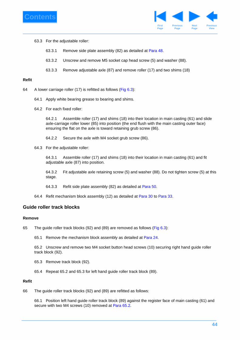
44
ContentsPrevious
PageFirst Page
Next Page
Previous View
63.3 For the adjustable roller:
63.3.1 Remove side plate assembly (82) as detailed at Para 48.
63.3.2 Unscrew and remove M5 socket cap head screw (5) and washer (88).
63.3.3 Remove adjustable axle (87) and remove roller (17) and two shims (18)
Refit
64 A lower carriage roller (17) is refitted as follows (Fig 6.3):
64.1 Apply white bearing grease to bearing and shims.
64.2 For each fixed roller:
64.2.1 Assemble roller (17) and shims (18) into their location in main casting (61) and slide axle-carriage roller lower (85) into position (the end flush with the main casting outer face) ensuring the flat on the axle is toward retaining grub screw (86).
64.2.2 Secure the axle with M4 socket grub screw (86).
64.3 For the adjustable roller:
64.3.1 Assemble roller (17) and shims (18) into their location in main casting (61) and fit adjustable axle (87) into position.
64.3.2 Fit adjustable axle retaining screw (5) and washer (88). Do not tighten screw (5) at this stage.
64.3.3 Refit side plate assembly (82) as detailed at Para 50.
64.4 Refit mechanism block assembly (12) as detailed at Para 30 to Para 33.
Guide roller track blocks
Remove
65 The guide roller track blocks (92) and (89) are removed as follows (Fig 6.3):
65.1 Remove the mechanism block assembly as detailed at Para 24.
65.2 Unscrew and remove two M4 socket button head screws (10) securing right hand guide roller track block (92).
65.3 Remove track block (92).
65.4 Repeat 65.2 and 65.3 for left hand guide roller track block (89).
Refit
66 The guide roller track blocks (92) and (89) are refitted as follows:
66.1 Position left hand guide roller track block (89) against the register face of main casting (61) and secure with two M4 screws (10) removed at Para 65.2.
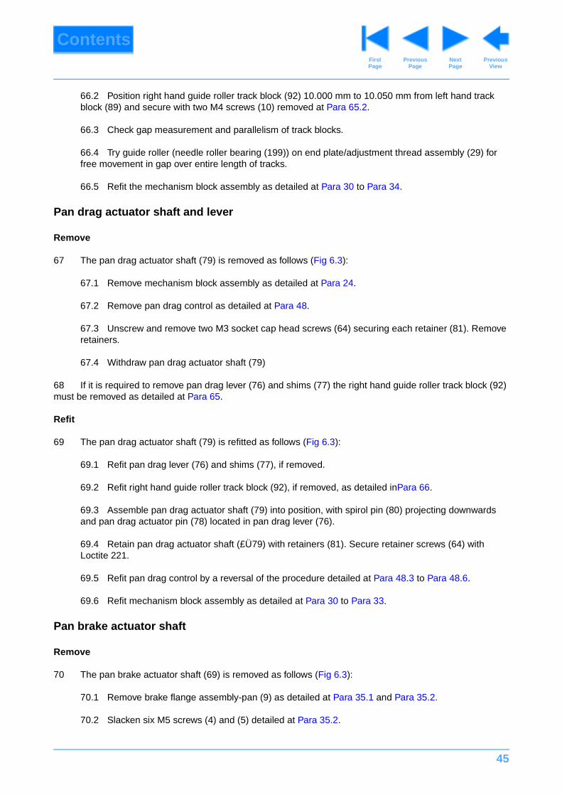
45
ContentsPrevious
PageFirst Page
Next Page
Previous View
66.2 Position right hand guide roller track block (92) 10.000 mm to 10.050 mm from left hand track block (89) and secure with two M4 screws (10) removed at Para 65.2.
66.3 Check gap measurement and parallelism of track blocks.
66.4 Try guide roller (needle roller bearing (199)) on end plate/adjustment thread assembly (29) for free movement in gap over entire length of tracks.
66.5 Refit the mechanism block assembly as detailed at Para 30 to Para 34.
Pan drag actuator shaft and lever
Remove
67 The pan drag actuator shaft (79) is removed as follows (Fig 6.3):
67.1 Remove mechanism block assembly as detailed at Para 24.
67.2 Remove pan drag control as detailed at Para 48.
67.3 Unscrew and remove two M3 socket cap head screws (64) securing each retainer (81). Remove retainers.
67.4 Withdraw pan drag actuator shaft (79)
68 If it is required to remove pan drag lever (76) and shims (77) the right hand guide roller track block (92) must be removed as detailed at Para 65.
Refit
69 The pan drag actuator shaft (79) is refitted as follows (Fig 6.3):
69.1 Refit pan drag lever (76) and shims (77), if removed.
69.2 Refit right hand guide roller track block (92), if removed, as detailed inPara 66.
69.3 Assemble pan drag actuator shaft (79) into position, with spirol pin (80) projecting downwards and pan drag actuator pin (78) located in pan drag lever (76).
69.4 Retain pan drag actuator shaft (£Ü79) with retainers (81). Secure retainer screws (64) with Loctite 221.
69.5 Refit pan drag control by a reversal of the procedure detailed at Para 48.3 to Para 48.6.
69.6 Refit mechanism block assembly as detailed at Para 30 to Para 33.
Pan brake actuator shaft
Remove
70 The pan brake actuator shaft (69) is removed as follows (Fig 6.3):
70.1 Remove brake flange assembly-pan (9) as detailed at Para 35.1 and Para 35.2.
70.2 Slacken six M5 screws (4) and (5) detailed at Para 35.2.
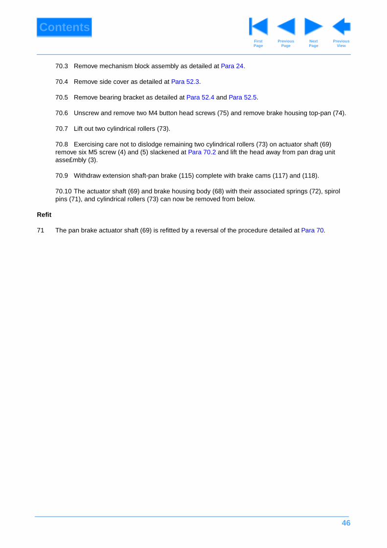
46
ContentsPrevious
PageFirst Page
Next Page
Previous View
70.3 Remove mechanism block assembly as detailed at Para 24.
70.4 Remove side cover as detailed at Para 52.3.
70.5 Remove bearing bracket as detailed at Para 52.4 and Para 52.5.
70.6 Unscrew and remove two M4 button head screws (75) and remove brake housing top-pan (74).
70.7 Lift out two cylindrical rollers (73).
70.8 Exercising care not to dislodge remaining two cylindrical rollers (73) on actuator shaft (69) remove six M5 screw (4) and (5) slackened at Para 70.2 and lift the head away from pan drag unit asse£mbly (3).
70.9 Withdraw extension shaft-pan brake (115) complete with brake cams (117) and (118).
70.10 The actuator shaft (69) and brake housing body (68) with their associated springs (72), spirol pins (71), and cylindrical rollers (73) can now be removed from below.
Refit
71 The pan brake actuator shaft (69) is refitted by a reversal of the procedure detailed at Para 70.

47
ContentsPrevious
PageFirst Page
Next Page
Previous View
Section 6
Illustrated Parts List
Contents Para
IIllustrated Parts List. . . . . . . . . . . . . . . . . . . . . . . . . . . . . . . . . . . . . . . . . . . . . . . . . . . . . . . . . . . . . . . . . . . 47
Illustrated Parts List. . . . . . . . . . . . . . . . . . . . . . . . . . . . . . . . . . . . . . . . . . . . . . . . . . . . . . . . . . . . . . . . . . . . . 48
Illustrated Parts List. . . . . . . . . . . . . . . . . . . . . . . . . . . . . . . . . . . . . . . . . . . . . . . . . . . . . . . . . . . . . . . . . . . . . 48
Illustrations Page
Fig 6.1 Vision 30 Pan and Tilt Head . . . . . . . . . . . . . . . . . . . . . . . . . . . . . . . . . . . . . . . . . . . . . . . . . . . . . . . 49
Fig 6.2 Secondary Mechanism Assembly . . . . . . . . . . . . . . . . . . . . . . . . . . . . . . . . . . . . . . . . . . . . . . . . . . . 52
Fig 6.3 Primary Mechanism Assembly . . . . . . . . . . . . . . . . . . . . . . . . . . . . . . . . . . . . . . . . . . . . . . . . . . . . . 56
Fig 6.4 Side Plate Assembly . . . . . . . . . . . . . . . . . . . . . . . . . . . . . . . . . . . . . . . . . . . . . . . . . . . . . . . . . . . . . 61
Fig 6.5 Tilt Drag Unit Assembly. . . . . . . . . . . . . . . . . . . . . . . . . . . . . . . . . . . . . . . . . . . . . . . . . . . . . . . . . . . 63
Fig 6.6 Mechanism Block and Secondary Spring Assemblies . . . . . . . . . . . . . . . . . . . . . . . . . . . . . . . . . . . 66
Fig 6.7 End Plate/Adjustment Thread Assembly. . . . . . . . . . . . . . . . . . . . . . . . . . . . . . . . . . . . . . . . . . . . . . 68
Fig 6.8 Platform Assembly . . . . . . . . . . . . . . . . . . . . . . . . . . . . . . . . . . . . . . . . . . . . . . . . . . . . . . . . . . . . . . 70
Fig 6.9 Pan Drag Unit Assembly . . . . . . . . . . . . . . . . . . . . . . . . . . . . . . . . . . . . . . . . . . . . . . . . . . . . . . . . . . 72
Fig 6.10 Quadrant Assembly. . . . . . . . . . . . . . . . . . . . . . . . . . . . . . . . . . . . . . . . . . . . . . . . . . . . . . . . . . . . . 74
Fig 6.11 Pan Bar Assembly. . . . . . . . . . . . . . . . . . . . . . . . . . . . . . . . . . . . . . . . . . . . . . . . . . . . . . . . . . . . . . 76
Fig 6.12 Spherical Base . . . . . . . . . . . . . . . . . . . . . . . . . . . . . . . . . . . . . . . . . . . . . . . . . . . . . . . . . . . . . . . . 78
Fig 6.13 Flat Base Assembly . . . . . . . . . . . . . . . . . . . . . . . . . . . . . . . . . . . . . . . . . . . . . . . . . . . . . . . . . . . . 80
Fig 6.14 Automatic Wedge Adaptor and Wedge Assemblies . . . . . . . . . . . . . . . . . . . . . . . . . . . . . . . . . . . . 82
Fig 6.15 Composite Spare Parts . . . . . . . . . . . . . . . . . . . . . . . . . . . . . . . . . . . . . . . . . . . . . . . . . . . . . . . . . . 84
Introduction
1 This parts list is issued for the Vision 30 pan and tilt heads manufactured by VINTEN BROADCAST LIMITED, Western Way, Bury St Edmunds, Suffolk, IP33 3TB, England.
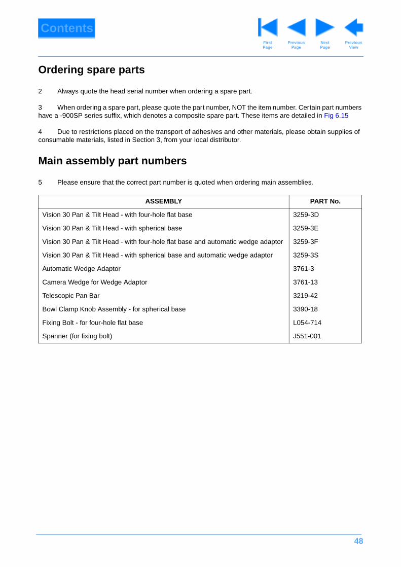
48
ContentsPrevious
PageFirst Page
Next Page
Previous View
Ordering spare parts
2 Always quote the head serial number when ordering a spare part.
3 When ordering a spare part, please quote the part number, NOT the item number. Certain part numbers have a -900SP series suffix, which denotes a composite spare part. These items are detailed in Fig 6.15
4 Due to restrictions placed on the transport of adhesives and other materials, please obtain supplies of consumable materials, listed in Section 3, from your local distributor.
Main assembly part numbers
5 Please ensure that the correct part number is quoted when ordering main assemblies.
ASSEMBLY PART No.
Vision 30 Pan & Tilt Head - with four-hole flat base 3259-3D
Vision 30 Pan & Tilt Head - with spherical base 3259-3E
Vision 30 Pan & Tilt Head - with four-hole flat base and automatic wedge adaptor 3259-3F
Vision 30 Pan & Tilt Head - with spherical base and automatic wedge adaptor 3259-3S
Automatic Wedge Adaptor 3761-3
Camera Wedge for Wedge Adaptor 3761-13
Telescopic Pan Bar 3219-42
Bowl Clamp Knob Assembly - for spherical base 3390-18
Fixing Bolt - for four-hole flat base L054-714
Spanner (for fixing bolt) J551-001
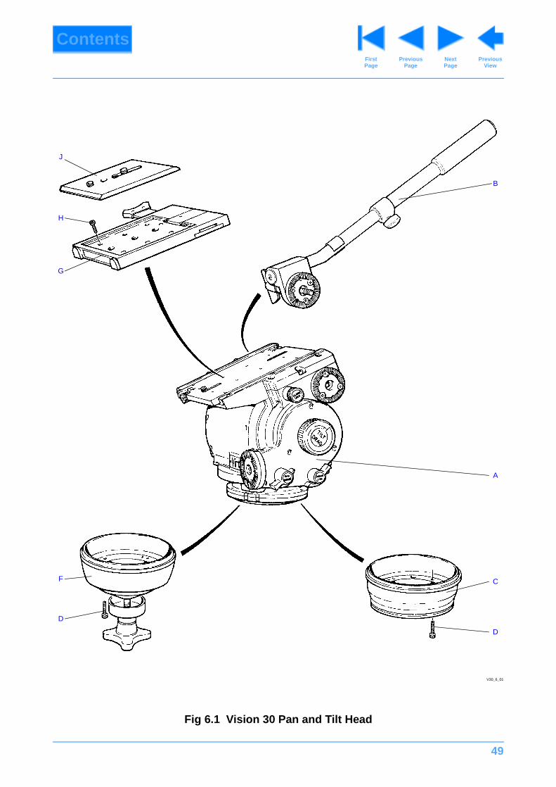
49
ContentsPrevious
PageFirst Page
Next Page
Previous View
Fig 6.1 Vision 30 Pan and Tilt Head
B
J
H
G
A
C
D
F
D
V30_6_01
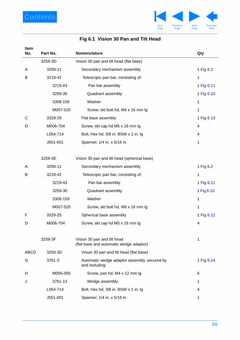
50
ContentsPrevious
PageFirst Page
Next Page
Previous View
Fig 6.1 Vision 30 Pan and Tilt Head
Item No. Part No. Nomenclature Qty
3259-3D Vision 30 pan and tilt head (flat base)
A 3259-11 Secondary mechanism assembly 1 Fig 6.2
B 3219-42 Telescopic pan bar, consisting of: 1
3219-43 Pan bar assembly 1 Fig 6.11
3259-30 Quadrant assembly 1 Fig 6.10
3308-159 Washer 1
M007-520 Screw, skt butt hd, M6 x 16 mm lg 1
C 3329-29 Flat base assembly 1 Fig 6.13
D M006-704 Screw, skt cap hd M5 x 16 mm lg 4
L054-714 Bolt, Hex hd, 3/8 in. BSW x 1 in. lg 4
J551-001 Spanner, 1/4 in. x 5/16 in. 1
3259-3E Vision 30 pan and tilt head (spherical base)
A 3259-11 Secondary mechanism assembly 1 Fig 6.2
B 3219-42 Telescopic pan bar, consisting of: 1
3219-43 Pan bar assembly 1 Fig 6.11
3259-30 Quadrant assembly 1 Fig 6.10
3308-159 Washer 1
M007-520 Screw, skt butt hd, M6 x 16 mm lg 1
F 3329-25 Spherical base assembly 1 Fig 6.12
D M006-704 Screw, skt cap hd M5 x 16 mm lg 4
3259-3F Vision 30 pan and tilt head(flat base and automatic wedge adaptor)
1
ABCD 3259-3D Vision 30 pan and tilt head (flat base)
G 3761-3 Automatic wedge adaptor assembly, secured by and including:
1 Fig 6.14
H M005-005 Screw, pan hd, M4 x 12 mm lg 6
J 3761-13 Wedge assembly 1
L054-714 Bolt, Hex hd, 3/8 in. BSW x 1 in. lg 4
J551-001 Spanner, 1/4 in. x 5/16 in. 1
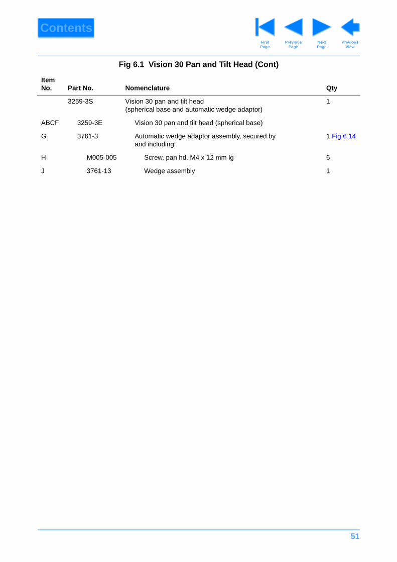
51
ContentsPrevious
PageFirst Page
Next Page
Previous View
3259-3S Vision 30 pan and tilt head (spherical base and automatic wedge adaptor)
1
ABCF 3259-3E Vision 30 pan and tilt head (spherical base)
G 3761-3 Automatic wedge adaptor assembly, secured byand including:
1 Fig 6.14
H M005-005 Screw, pan hd. M4 x 12 mm lg 6
J 3761-13 Wedge assembly 1
Fig 6.1 Vision 30 Pan and Tilt Head (Cont)
Item No. Part No. Nomenclature Qty
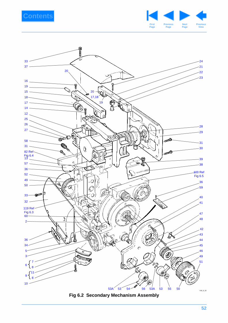
52
ContentsPrevious
PageFirst Page
Next Page
Previous View
Fig 6.2 Secondary Mechanism AssemblyV30_6_02
2433
3720
16
19
15
18
17
14
12
25
26
27
22
23
29
28
21
30
40
31
20
17,18
19
58
31
13 39
38
100 Ref Fig 6.5
59
41
47
48
36
42
44
43
45
49
46
51
50555353A 5653
36
52
49
50
82 RefFig 6.4
57
33
32
119 Ref Fig 6.3
5
3
67
8
11
8
10
9
60
36
34
2
53A54

53
ContentsPrevious
PageFirst Page
Next Page
Previous View
Fig 6.2 Secondary Mechanism Assembly
Item No. Part No. Nomenclature Qty
1 Ref 3259-11 Assembly, Secondary Mechanism, comprising: 1
2 3259-14 Assembly, primary mechanism 1 Fig 6.3
3 3259-19 Assembly, pan drag unit, secured by: 1 Fig 6.9
NI M006-704 Screw, skt cap hd M5 x 16 mm lg 4
5 M006-703 Screw, skt cap hd M5 x 12 mm lg 2
6 3259-24 Assembly, brake segment, comprising: 1
7 3259-302 Segment, brake 1
8 3259-301 Pad, brake 1
9 3259-22 Assembly, brake flange - pan, secured by and comprising: 1
10 M005-506 Screw, butt hd M4 x 16mm lg 2
11 3259-329 Flange, brake - pan 1
8 3259-301 Pad, brake 1
12 3259-15 Assembly, mechanism block 1 Fig 6.6
13 3259-242 Shim, load beam, secured by: 2
14 M006-505 Screw, skt butt hd M5 x 12 mm lg 2
15 3259-247 Cross member - front, secured by: 1
16 M005-505 Screw, butt hd M4 x 12 mm lg 2
17 P603-003 Roller, yoke type, track INA RST05TNX 2
18 3259-210 Shim, carriage roller 4
19 3259-246 Axle, cross member roller, secured by: 2
20 M004-801 Screw, skt grub M3 x 5 mm lg 2
21 3259-248 Cross member - rear 1
16 M005-505 Screw, butt hd M4 x 12 mm lg 2
17 P603-003 Roller, yoke type, track INA RST05TNX 2
18 3259-210 Shim, carriage roller 4
19 3259-246 Axle, cross member roller, secured by: 2
20 M004-801 Screw, skt grub M3 x 5 mm lg 2
22 3259-245 Roller, lateral guide, secured by: 2
23 3259-244 Bush, lateral guide roller 2
24 M005-508 Screw, butt hd M4 x 20 mm lg 2
25 3259-232 Plunger, carriage assembly 2

54
ContentsPrevious
PageFirst Page
Next Page
Previous View
26 J532-037 Spring, compression Flexo 102908 2
27 3259-231 Plug, spring 2
28 J532-084 Spring, compression Terry Barnes 53700 1
29 3259-12 Assembly, end plate/adjustment thread, secured by: 1 Fig 6.7
30 M007-524 Screw, skt butt hd M6 x 25 mm lg 6
31 M007-520 Screw, skt butt hd M6 x 16 mm lg 1
32 3259-250 Cover, front - crosstie, secured by: 1
33 M005-706 Screw, skt cap hd M4 x 16 mm l 4
34 1423-2 Nameplate (medium), secured by: 1
35 (NI) Z001-046 Tape, adhesive Scotch Y909 A/R
36 L102-001 Screw, hammerdrive, 00 x 1/8 in. 2
37 3259-251 Cover, top - crosstie, secured by: 1
33 M005-706 Screw, skt cap hd M4 x 16 mm l 4
38 3259-13 Assembly, platform, secured by: 1 Fig 6.8
31 M007-520 Screw, skt butt hd M6 x 16 mm lg 4
39 M007-705 Screw, skt cap hd M6 x 20 mm lg 3
40 3259-314 Cover, side, secured by: 1
41 M005-718 Screw, skt cap hd M4 x 12 mm lg 4
42 M005-704 Screw, skt cap hd M4 x 10 mm lg 4
43 P602-028 Washer, thrust INA LS1730 1
44 P602-026 Bearing, needle thrust INA AXK1730 1
45 P602-027 Washer, thrust INA AS1730 1
46 3259-274 Centre, drag knob 1
47 3259-275 Retainer, drag knob, secured by: 1
48 M003-102 Screw, csk hd M2.5 x 6 mm lg 2
49 3199-244 Knob, drag, secured by: 1
50 M005-101 Screw, csk hd M4 x 6 mm lg 3
51 3199-299 Label, tilt drag
49 3199-244 Knob, drag, secured by: 1
50 M005-101 Screw, csk hd M4 x 6 mm lg 3
Fig 6.2 Secondary Mechanism Assembly (Cont)
Item No. Part No. Nomenclature Qty
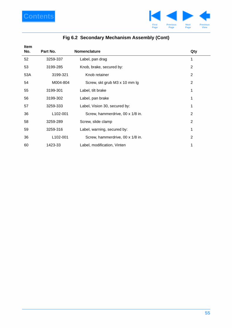
55
ContentsPrevious
PageFirst Page
Next Page
Previous View
52 3259-337 Label, pan drag 1
53 3199-285 Knob, brake, secured by: 2
53A 3199-321 Knob retainer 2
54 M004-804 Screw, skt grub M3 x 10 mm lg 2
55 3199-301 Label, tilt brake 1
56 3199-302 Label, pan brake 1
57 3259-333 Label, Vision 30, secured by: 1
36 L102-001 Screw, hammerdrive, 00 x 1/8 in. 2
58 3259-289 Screw, slide clamp 2
59 3259-316 Label, warning, secured by: 1
36 L102-001 Screw, hammerdrive, 00 x 1/8 in. 2
60 1423-33 Label, modification, Vinten 1
Fig 6.2 Secondary Mechanism Assembly (Cont)
Item No. Part No. Nomenclature Qty
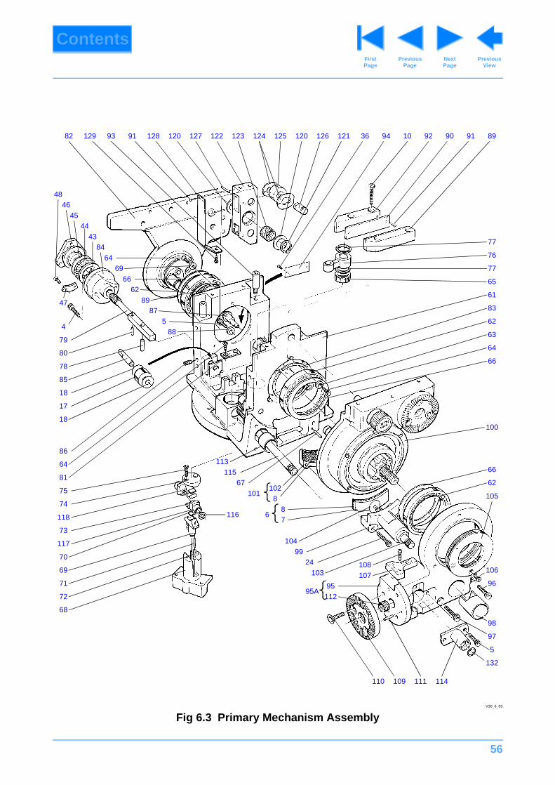
56
ContentsPrevious
PageFirst Page
Next Page
Previous View
Fig 6.3 Primary Mechanism Assembly
89919092109436121126120125124123122127120128919312982
77
76
77
65
61
83
62
63
64
66
66
62
100
105
106
96
97
5
132
98
114111109110
95A95112
113115
67101
8
6
102
87
104
103
9924 108
107
68
72
71
69
70
117
73
118
74
75
81
64
86
116
18
17
18
85
78
80
79
4
47
62
587
89
88
6669
6484
4344
4546
48
V30_6_03
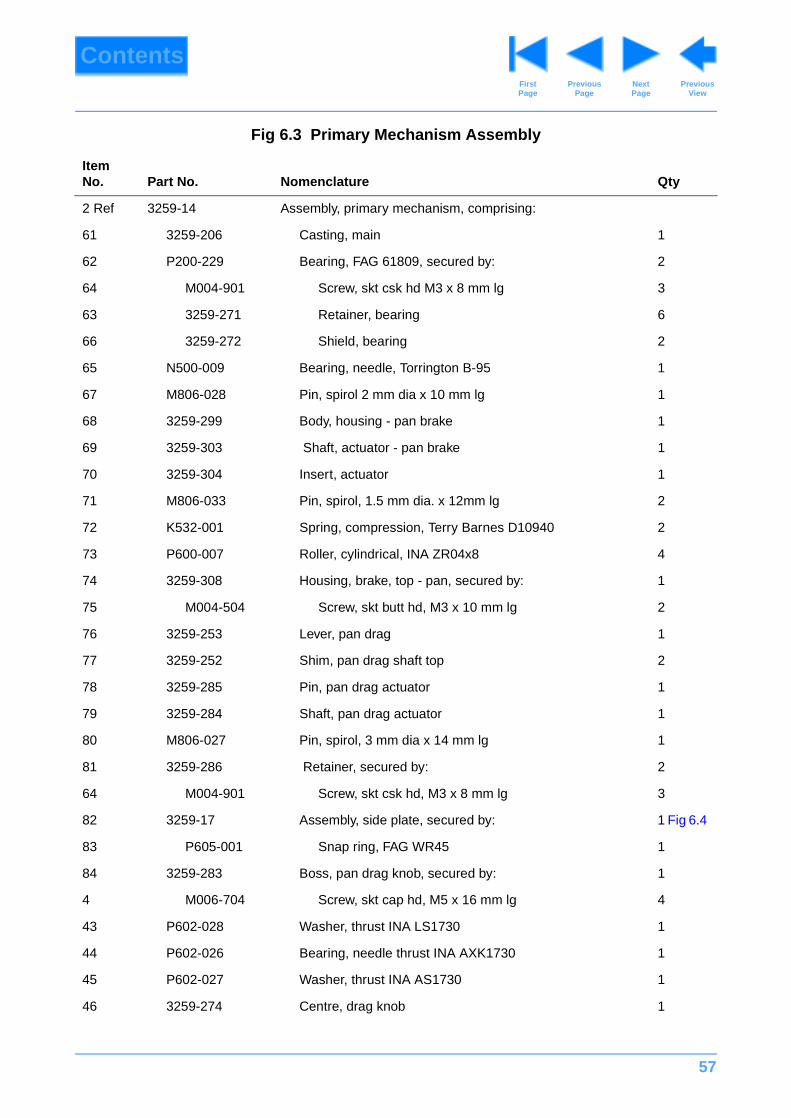
57
ContentsPrevious
PageFirst Page
Next Page
Previous View
Fig 6.3 Primary Mechanism Assembly
Item No. Part No. Nomenclature Qty
2 Ref 3259-14 Assembly, primary mechanism, comprising:
61 3259-206 Casting, main 1
62 P200-229 Bearing, FAG 61809, secured by: 2
64 M004-901 Screw, skt csk hd M3 x 8 mm lg 3
63 3259-271 Retainer, bearing 6
66 3259-272 Shield, bearing 2
65 N500-009 Bearing, needle, Torrington B-95 1
67 M806-028 Pin, spirol 2 mm dia x 10 mm lg 1
68 3259-299 Body, housing - pan brake 1
69 3259-303 Shaft, actuator - pan brake 1
70 3259-304 Insert, actuator 1
71 M806-033 Pin, spirol, 1.5 mm dia. x 12mm lg 2
72 K532-001 Spring, compression, Terry Barnes D10940 2
73 P600-007 Roller, cylindrical, INA ZR04x8 4
74 3259-308 Housing, brake, top - pan, secured by: 1
75 M004-504 Screw, skt butt hd, M3 x 10 mm lg 2
76 3259-253 Lever, pan drag 1
77 3259-252 Shim, pan drag shaft top 2
78 3259-285 Pin, pan drag actuator 1
79 3259-284 Shaft, pan drag actuator 1
80 M806-027 Pin, spirol, 3 mm dia x 14 mm lg 1
81 3259-286 Retainer, secured by: 2
64 M004-901 Screw, skt csk hd, M3 x 8 mm lg 3
82 3259-17 Assembly, side plate, secured by: 1 Fig 6.4
83 P605-001 Snap ring, FAG WR45 1
84 3259-283 Boss, pan drag knob, secured by: 1
4 M006-704 Screw, skt cap hd, M5 x 16 mm lg 4
43 P602-028 Washer, thrust INA LS1730 1
44 P602-026 Bearing, needle thrust INA AXK1730 1
45 P602-027 Washer, thrust INA AS1730 1
46 3259-274 Centre, drag knob 1

58
ContentsPrevious
PageFirst Page
Next Page
Previous View
47 3259-275 Retainer, drag knob, secured by: 1
48 M003-102 Screw, csk hd, M2.5 x 6 mm lg 2
17 P603-003 Roller, yoke type, track INA RST05TNX 2
18 3259-210 Shim, carriage roller 4
85 3259-209 Axle, carriage roller lower 3
86 M005-801 Screw, skt grub, dog pt, M4 x 5 mm lg 3
87 3259-211 Axle, adjustable, secured by: 1
5 M006-703 Screw, skt cap hd, M5 x 12 mm lg 1
88 M600-006 Washer, M5 1
89 3259-213 Block, guide roller track LH 1
10 (NI) M005-506 Screw, skt butt hd, M4 x 16 mm lg 2
90 (NI) 3259-214 Track, guide roller, secured by: 1
91 (NI) L800-007 Pin, spirol, headed, 5/64 in. dia. x 1/4 in. lg 2
92 3259-212 Block, guide roller track RH, secured by: 1
10 M005-506 Screw, skt button hd. M4 x 16mm lg 2
90 3259-214 Track, guide roller, secured by: 1
91 L800-007 Pin, spirol, headed, 5/64 in. dia. x 1/4 in. lg 2
93 3259-249 Pin, locating 4
94 1423-3 Nameplate, secured by: 1
35 (NI) Z001-046 Tape, adhesive Scotch Y909 A/R
36 L102-001 Screw, hammerdrive, 00 x 1/8 in. 2
95A 3259-900SP Bracket assembly, bearing, comprising:
112 M850-006 Insert, helicoil, M8 x 1 1/2D lg 1
95 3259-207 Bracket, bearing, secured by: 1
96 M006-705 Screw, skt cap hd, M5 x 20 mm lg 1
97 M006-708 Screw, skt cap hd, M5 x 35 mm lg 3
62 P200-229 Bearing, FAG 61809 2
66 3259-272 Shield, bearing 2
98 3259-311 Liner, Bore - tilt brake 1
99 3259-312 Body, brake housing - tilt 1
100 3259-18 Assembly, tilt drag unit, secured by: 1 Fig 6.5
Fig 6.3 Primary Mechanism Assembly (Cont)
Item No. Part No. Nomenclature Qty
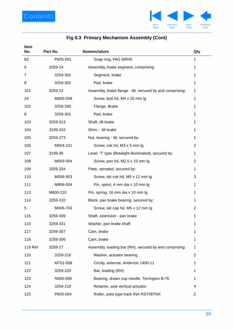
59
ContentsPrevious
PageFirst Page
Next Page
Previous View
83 P605-001 Snap ring, FAG WR45 1
6 3259-24 Assembly, brake segment, comprising: 1
7 3259-302 Segment, brake 1
8 3259-301 Pad, brake 1
101 3259-23 Assembly, brake flange - tilt, secured by and comprising: 1
24 M005-508 Screw, butt hd, M4 x 20 mm lg 2
102 3259-330 Flange, Brake 1
8 3259-301 Pad, brake 1
103 3259-313 Shaft, tilt brake 1
104 3199-310 Shim, - tilt brake 1
105 3259-273 Nut, bearing - tilt, secured by: 1
106 M004-101 Screw, csk hd, M3 x 5 mm lg 2
107 3199-35 Level, 'T' type (Betalight illuminated), secured by: 1
108 M003-004 Screw, pan hd, M2.5 x 10 mm lg 2
109 3259-334 Plate, serrated, secured by: 1
110 M006-903 Screw, skt csk hd, M5 x 12 mm lg 3
111 M806-004 Pin, spirol, 4 mm dia x 10 mm lg 1
113 M800-210 Pin, spring, 16 mm dia x 10 mm lg 1
114 3259-310 Block, pan brake bearing, secured by: 1
5 M006-703 Screw, skt cap hd, M5 x 12 mm lg 2
115 3259-309 Shaft, extension - pan brake 1
116 3259-331 Washer, pan brake shaft 1
117 3259-307 Cam, brake 1
118 3259-306 Cam, brake 1
119 Ref 3259-27 Assembly, loading bar (RH), secured by and comprising: 1
120 3259-216 Washer, actuator bearing 2
121 M701-008 Circlip, external, Anderton 1400-11 1
122 3259-220 Bar, loading (RH) 1
123 N500-008 Bearing, drawn cup needle, Torrington B-76 1
124 3259-218 Retainer, axle vertical actuator 4
125 P603-004 Roller, yoke type track INA RST06TNX 2
Fig 6.3 Primary Mechanism Assembly (Cont)
Item No. Part No. Nomenclature Qty
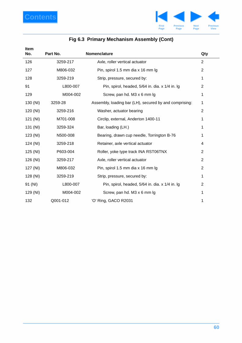
60
ContentsPrevious
PageFirst Page
Next Page
Previous View
126 3259-217 Axle, roller vertical actuator 2
127 M806-032 Pin, spirol 1.5 mm dia x 16 mm lg 2
128 3259-219 Strip, pressure, secured by: 1
91 L800-007 Pin, spirol, headed, 5/64 in. dia. x 1/4 in. lg 2
129 M004-002 Screw, pan hd. M3 x 6 mm lg 1
130 (NI) 3259-28 Assembly, loading bar (LH), secured by and comprising: 1
120 (NI) 3259-216 Washer, actuator bearing 2
121 (NI) M701-008 Circlip, external, Anderton 1400-11 1
131 (NI) 3259-324 Bar, loading (LH.) 1
123 (NI) N500-008 Bearing, drawn cup needle, Torrington B-76 1
124 (NI) 3259-218 Retainer, axle vertical actuator 4
125 (NI) P603-004 Roller, yoke type track INA RST06TNX 2
126 (NI) 3259-217 Axle, roller vertical actuator 2
127 (NI) M806-032 Pin, spirol 1.5 mm dia x 16 mm lg 2
128 (NI) 3259-219 Strip, pressure, secured by: 1
91 (NI) L800-007 Pin, spirol, headed, 5/64 in. dia. x 1/4 in. lg 2
129 (NI) M004-002 Screw, pan hd. M3 x 6 mm lg 1
132 Q001-012 'O' Ring, GACO R2031 1
Fig 6.3 Primary Mechanism Assembly (Cont)
Item No. Part No. Nomenclature Qty
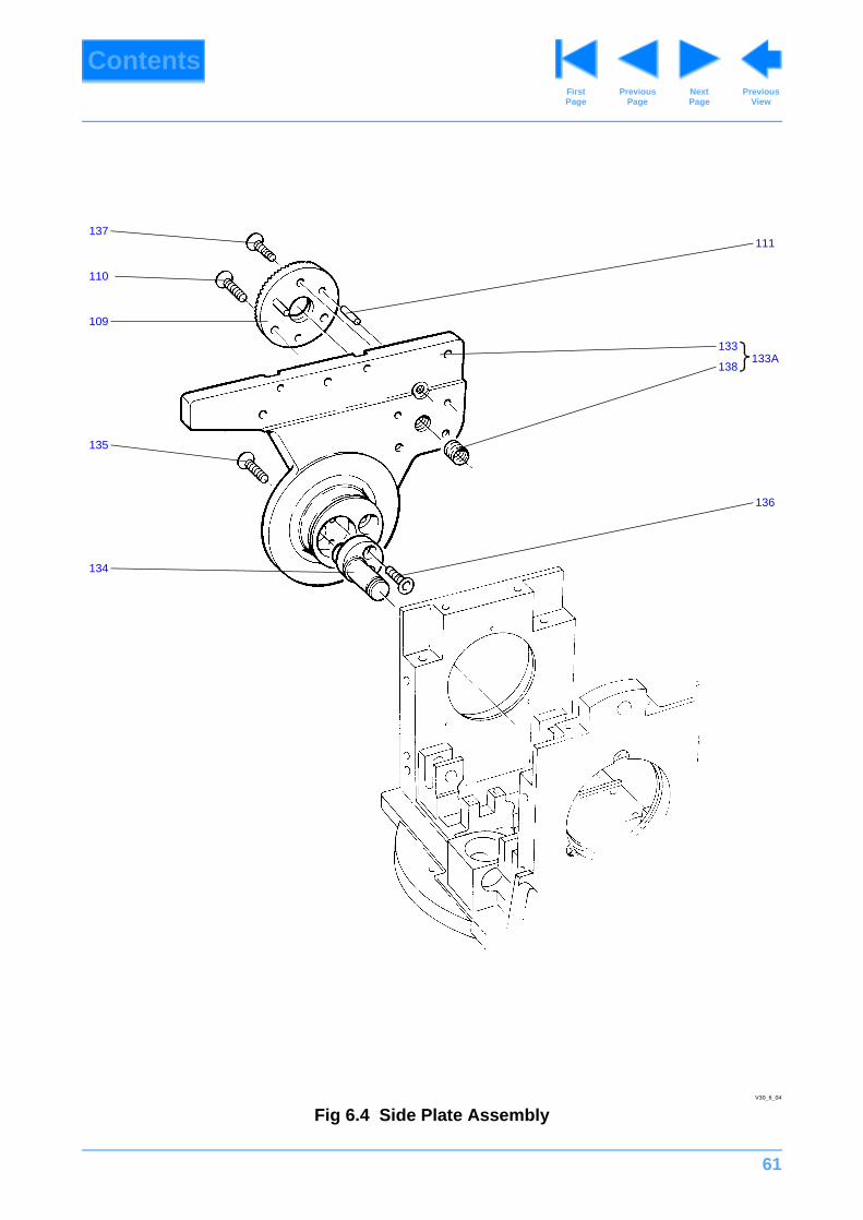
61
ContentsPrevious
PageFirst Page
Next Page
Previous View
Fig 6.4 Side Plate Assembly
137
110
109
134
111
135
138
133133A
136
V30_6_04
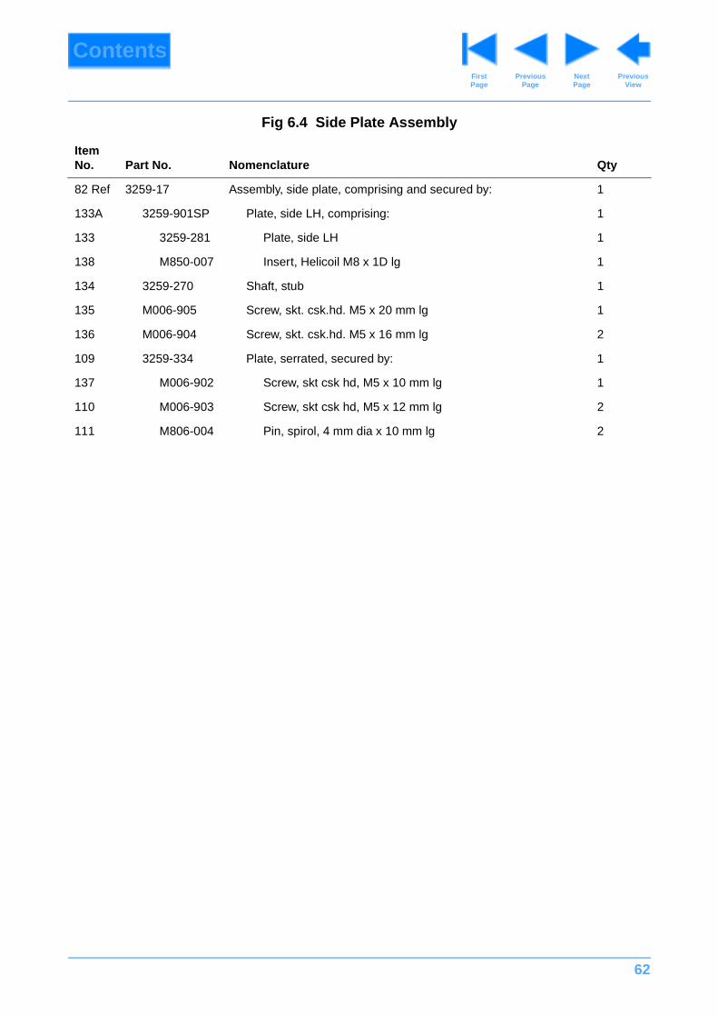
62
ContentsPrevious
PageFirst Page
Next Page
Previous View
Fig 6.4 Side Plate Assembly
Item No. Part No. Nomenclature Qty
82 Ref 3259-17 Assembly, side plate, comprising and secured by: 1
133A 3259-901SP Plate, side LH, comprising: 1
133 3259-281 Plate, side LH 1
138 M850-007 Insert, Helicoil M8 x 1D lg 1
134 3259-270 Shaft, stub 1
135 M006-905 Screw, skt. csk.hd. M5 x 20 mm lg 1
136 M006-904 Screw, skt. csk.hd. M5 x 16 mm lg 2
109 3259-334 Plate, serrated, secured by: 1
137 M006-902 Screw, skt csk hd, M5 x 10 mm lg 1
110 M006-903 Screw, skt csk hd, M5 x 12 mm lg 2
111 M806-004 Pin, spirol, 4 mm dia x 10 mm lg 2
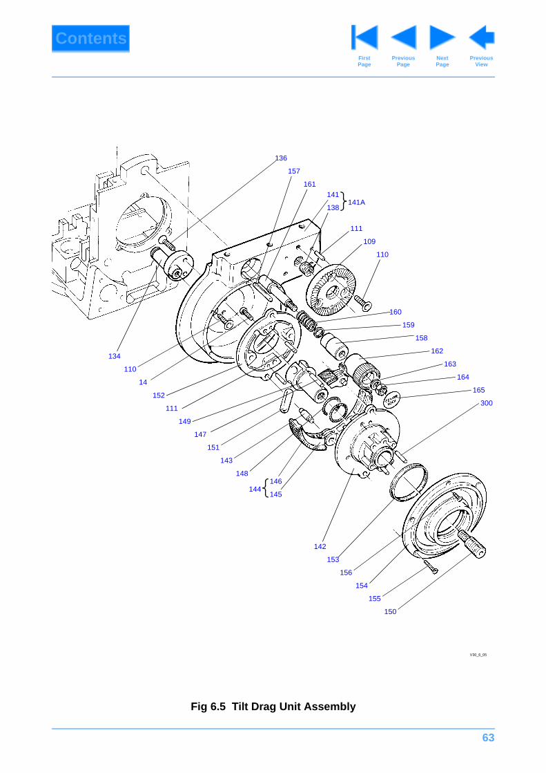
63
ContentsPrevious
PageFirst Page
Next Page
Previous View
Fig 6.5 Tilt Drag Unit Assembly
134
V30_6_05
136
157
161
111
141
138141A
300
110
160
159
158
162
163
164
165152
109
150
155
154
156
153
142
145
146144
110
14
148
143
151
147
149
111
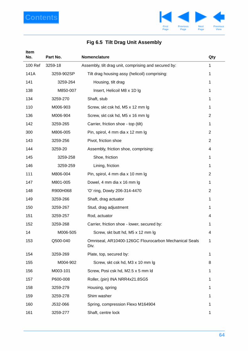
64
ContentsPrevious
PageFirst Page
Next Page
Previous View
Fig 6.5 Tilt Drag Unit Assembly
Item No. Part No. Nomenclature Qty
100 Ref 3259-18 Assembly, tilt drag unit, comprising and secured by: 1
141A 3259-902SP Tilt drag housing assy (helicoil) comprising: 1
141 3259-264 Housing, tilt drag 1
138 M850-007 Insert, Helicoil M8 x 1D lg 1
134 3259-270 Shaft, stub 1
110 M006-903 Screw, skt csk hd, M5 x 12 mm lg 1
136 M006-904 Screw, skt csk hd, M5 x 16 mm lg 2
142 3259-265 Carrier, friction shoe - top (tilt) 1
300 M806-005 Pin, spirol, 4 mm dia x 12 mm lg 2
143 3259-256 Pivot, friction shoe 2
144 3259-20 Assembly, friction shoe, comprising: 4
145 3259-258 Shoe, friction 1
146 3259-259 Lining, friction 1
111 M806-004 Pin, spirol, 4 mm dia x 10 mm lg 2
147 M801-005 Dowel, 4 mm dia x 16 mm lg 1
148 R900H068 'O' ring, Dowty 206-314-4470 2
149 3259-266 Shaft, drag actuator 1
150 3259-267 Stud, drag adjustment 1
151 3259-257 Rod, actuator 4
152 3259-268 Carrier, friction shoe - lower, secured by: 1
14 M006-505 Screw, skt butt hd, M5 x 12 mm lg 4
153 Q500-040 Omniseal, AR10400-126GC Flourocarbon Mechanical Seals Div.
1
154 3259-269 Plate, top, secured by: 1
155 M004-902 Screw, skt csk hd, M3 x 10 mm lg 8
156 M003-101 Screw, Posi csk hd, M2.5 x 5 mm ld 1
157 P600-008 Roller, (pin) INA NRR4x21.8SG5 1
158 3259-279 Housing, spring 1
159 3259-278 Shim washer 1
160 J532-066 Spring, compression Flexo M164904 1
161 3259-277 Shaft, centre lock 1
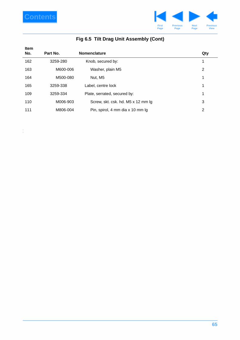
65
ContentsPrevious
PageFirst Page
Next Page
Previous View
#
#
162 3259-280 Knob, secured by: 1
163 M600-006 Washer, plain M5 2
164 M500-080 Nut, M5 1
165 3259-338 Label, centre lock 1
109 3259-334 Plate, serrated, secured by: 1
110 M006-903 Screw, skt. csk. hd. M5 x 12 mm lg 3
111 M806-004 Pin, spirol, 4 mm dia x 10 mm lg 2
Fig 6.5 Tilt Drag Unit Assembly (Cont)
Item No. Part No. Nomenclature Qty

66
ContentsPrevious
PageFirst Page
Next Page
Previous View
Fig 6.6 Mechanism Block and Secondary Spring Assemblies
172
V30_6_06
173
174
173
175
176
168
171
91
177
170
166
167
91
182
181
12
179
178
180
16912
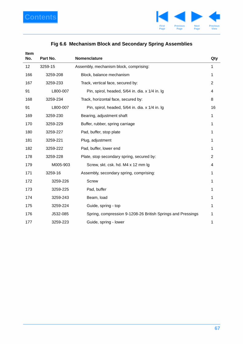
67
ContentsPrevious
PageFirst Page
Next Page
Previous View
Fig 6.6 Mechanism Block and Secondary Spring Assemblies
Item No. Part No. Nomenclature Qty
12 3259-15 Assembly, mechanism block, comprising: 1
166 3259-208 Block, balance mechanism 1
167 3259-233 Track, vertical face, secured by: 2
91 L800-007 Pin, spirol, headed, 5/64 in. dia. x 1/4 in. lg 4
168 3259-234 Track, horizontal face, secured by: 8
91 L800-007 Pin, spirol, headed, 5/64 in. dia. x 1/4 in. lg 16
169 3259-230 Bearing, adjustment shaft 1
170 3259-229 Buffer, rubber, spring carriage 1
180 3259-227 Pad, buffer, stop plate 1
181 3259-221 Plug, adjustment 1
182 3259-222 Pad, buffer, lower end 1
178 3259-228 Plate, stop secondary spring, secured by: 2
179 M005-903 Screw, skt. csk. hd. M4 x 12 mm lg 4
171 3259-16 Assembly, secondary spring, comprising: 1
172 3259-226 Screw 1
173 3259-225 Pad, buffer 1
174 3259-243 Beam, load 1
175 3259-224 Guide, spring - top 1
176 J532-085 Spring, compression 9-1208-26 British Springs and Pressings 1
177 3259-223 Guide, spring - lower 1
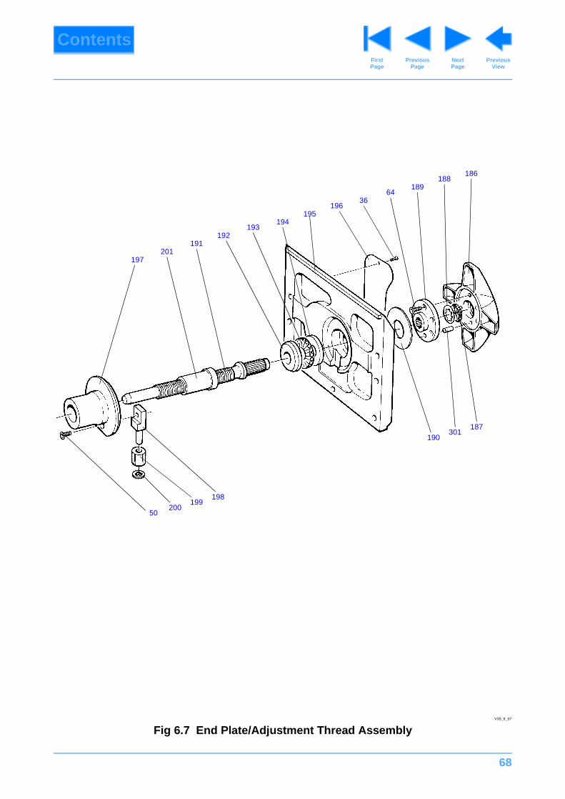
68
ContentsPrevious
PageFirst Page
Next Page
Previous View
Fig 6.7 End Plate/Adjustment Thread AssemblyV30_6_07
188189
6436
196195
194193
192
186
191201
187301
190
198199
20050
197
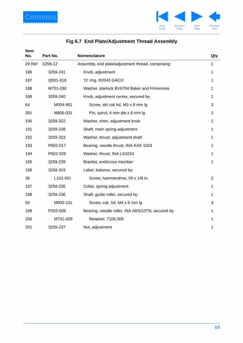
69
ContentsPrevious
PageFirst Page
Next Page
Previous View
Fig 6.7 End Plate/Adjustment Thread Assembly
Item No. Part No. Nomenclature Qty
29 Ref 3259-12 Assembly, end plate/adjustment thread, comprising: 1
186 3259-241 Knob, adjustment 1
187 Q001-018 ‘O' ring. R2043 GACO 1
188 M701-030 Washer, starlock BV6704 Baker and Finnemore 1
189 3259-240 Knob, adjustment centre, secured by: 1
64 M004-901 Screw, skt csk hd, M3 x 8 mm lg 3
301 M806-031 Pin, spirol, 4 mm dia x 8 mm lg 2
190 3259-322 Washer, shim, adjustment knob 1
191 3259-238 Shaft, main spring adjustment 1
192 3259-323 Washer, thrust, adjustment shaft 1
193 P602-017 Bearing, needle thrust, INA AXK 1024 1
194 P602-029 Washer, thrust, INA LS1024 1
195 3259-239 Bracket, end/cross member 1
196 3259-319 Label, balance, secured by:
36 L102-001 Screw, hammerdrive, 00 x 1/8 in. 2
197 3259-235 Collar, spring adjustment 1
198 3259-236 Shaft, guide roller, secured by: 1
50 M005-101 Screw, csk. hd. M4 x 6 mm lg 3
199 P203-005 Bearing, needle roller, INA NK5/10TN, secured by: 1
200 M701-029 Retainer, 7105.005 1
201 3259-237 Nut, adjustment 1
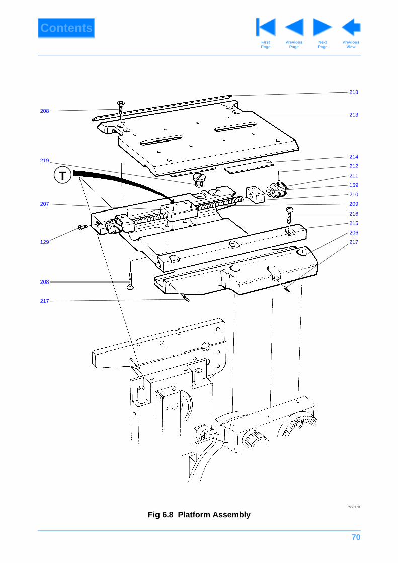
70
ContentsPrevious
PageFirst Page
Next Page
Previous View
Fig 6.8 Platform AssemblyV30_6_08
218
213
214
212
211
159
210
209
216
215
206
217
217
207
208
219
129
208
T
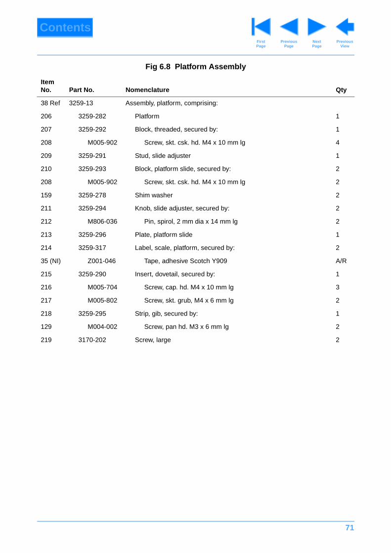
71
ContentsPrevious
PageFirst Page
Next Page
Previous View
Fig 6.8 Platform Assembly
Item No. Part No. Nomenclature Qty
38 Ref 3259-13 Assembly, platform, comprising:
206 3259-282 Platform 1
207 3259-292 Block, threaded, secured by: 1
208 M005-902 Screw, skt. csk. hd. M4 x 10 mm lg 4
209 3259-291 Stud, slide adjuster 1
210 3259-293 Block, platform slide, secured by: 2
208 M005-902 Screw, skt. csk. hd. M4 x 10 mm lg 2
159 3259-278 Shim washer 2
211 3259-294 Knob, slide adjuster, secured by: 2
212 M806-036 Pin, spirol, 2 mm dia x 14 mm lg 2
213 3259-296 Plate, platform slide 1
214 3259-317 Label, scale, platform, secured by: 2
35 (NI) Z001-046 Tape, adhesive Scotch Y909 A/R
215 3259-290 Insert, dovetail, secured by: 1
216 M005-704 Screw, cap. hd. M4 x 10 mm lg 3
217 M005-802 Screw, skt. grub, M4 x 6 mm lg 2
218 3259-295 Strip, gib, secured by: 1
129 M004-002 Screw, pan hd. M3 x 6 mm lg 2
219 3170-202 Screw, large 2
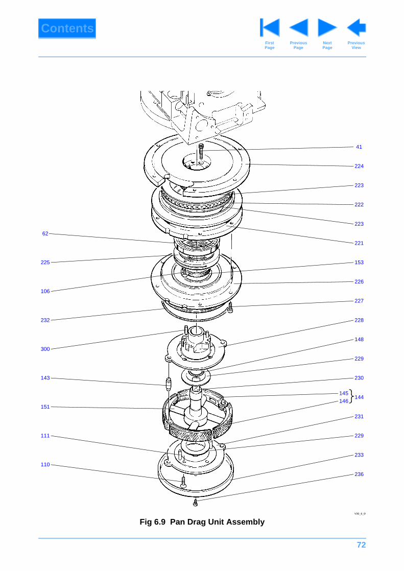
72
ContentsPrevious
PageFirst Page
Next Page
Previous View
Fig 6.9 Pan Drag Unit AssemblyV30_6_09
41
224
223
222
223
221
153
226
227
228
148
229
230
144
231
106
151
232
111
62
300
110
225
143
146145
229
233
236
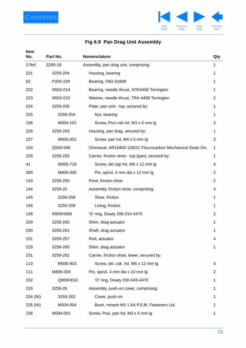
73
ContentsPrevious
PageFirst Page
Next Page
Previous View
Fig 6.9 Pan Drag Unit Assembly
Item No. Part No. Nomenclature Qty
3 Ref 3259-19 Assembly, pan drag unit, comprising: 1
221 3259-204 Housing, bearing 1
62 P200-229 Bearing, FAG 61809 1
222 N552-014 Bearing, needle thrust, NTA4458 Torrington 1
223 N552-015 Washer, needle thrust, TRA 4458 Torrington 2
224 3259-205 Plate, pan unit - top, secured by: 1
225 3259-254 Nut, bearing 1
106 M004-101 Screw, Pozi csk hd, M3 x 5 mm lg 2
226 3259-203 Housing, pan drag, secured by: 1
227 M005-001 Screw, pan hd, M4 x 5 mm lg 2
153 Q500-040 Omniseal, AR10400-126GC Flourocarbon Mechanical Seals Div. 1
228 3259-255 Carrier, friction shoe - top (pan), secured by: 1
41 M005-718 Screw, skt cap hd, M4 x 12 mm lg 4
300 M806-005 Pin, spirol, 4 mm dia x 12 mm lg 2
143 3259-256 Pivot, friction shoe 2
144 3259-20 Assembly, friction shoe, comprising: 4
145 3259-258 Shoe, friction 1
146 3259-259 Lining, friction 1
148 R900H068 'O' ring, Dowty 206-314-4470 2
229 3259-260 Shim, drag actuator 1
230 3259-261 Shaft, drag actuator 1
151 3259-257 Rod, actuator 4
229 3259-260 Shim, drag actuator 1
231 3259-262 Carrier, friction shoe, lower, secured by:
110 M006-903 Screw, skt. csk. hd. M5 x 12 mm lg 4
111 M806-004 Pin, spirol, 4 mm dia x 10 mm lg 2
232 Q900H032 'O’ ring, Dowty 200-043-4470 1
233 3259-26 Assembly, push-on cover, comprising: 1
234 (NI) 3259-263 Cover, push-on 1
235 (NI) M504-004 Bush, minarb M3 1.6A P.S.M. Fasteners Ltd. 1
236 M004-001 Screw, Posi, pan hd. M3 x 5 mm lg 1
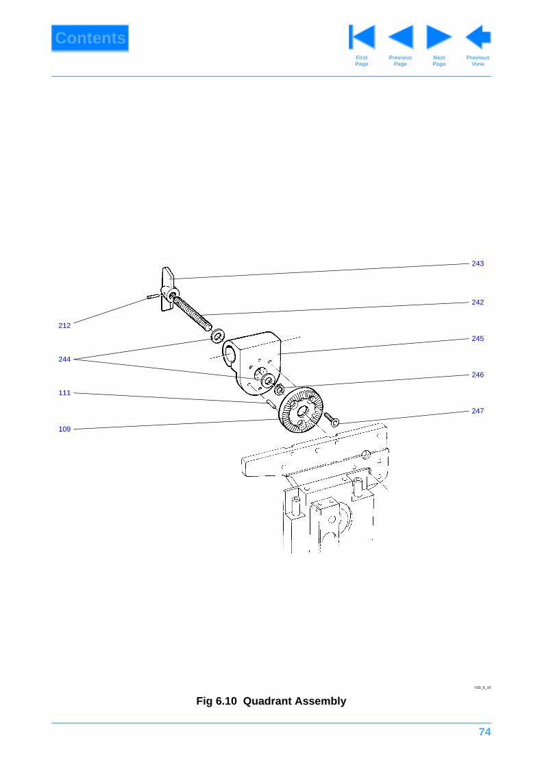
74
ContentsPrevious
PageFirst Page
Next Page
Previous View
Fig 6.10 Quadrant AssemblyV30_6_10
242
245
246
247
212
244
111
109
243
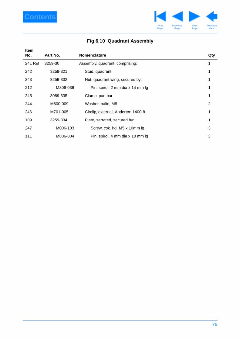
75
ContentsPrevious
PageFirst Page
Next Page
Previous View
Fig 6.10 Quadrant Assembly
Item No. Part No. Nomenclature Qty
241 Ref 3259-30 Assembly, quadrant, comprising: 1
242 3259-321 Stud, quadrant 1
243 3259-332 Nut, quadrant wing, secured by: 1
212 M806-036 Pin, spirol, 2 mm dia x 14 mm lg 1
245 3089-335 Clamp, pan bar 1
244 M600-009 Washer, palin, M8 2
246 M701-005 Circlip, external, Anderton 1400-8 1
109 3259-334 Plate, serrated, secured by: 1
247 M006-103 Screw, csk. hd. M5 x 10mm lg 3
111 M806-004 Pin, spirol, 4 mm dia x 10 mm lg 3
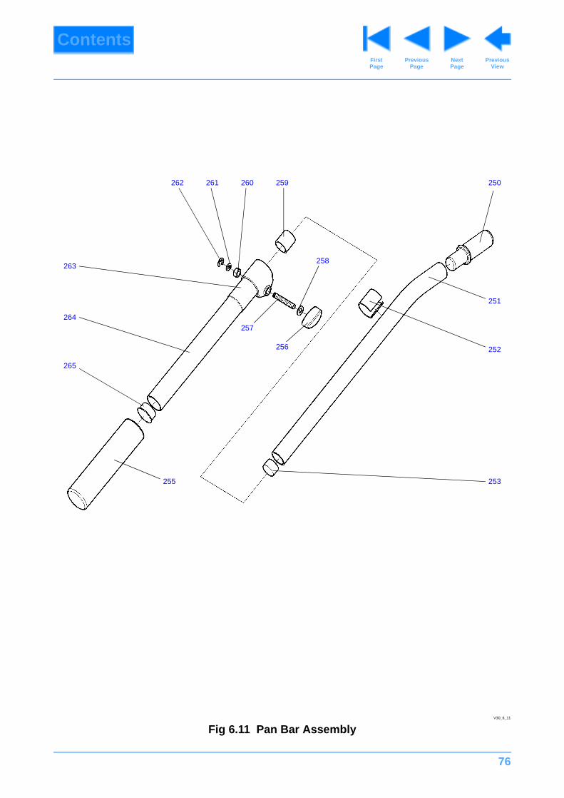
76
ContentsPrevious
PageFirst Page
Next Page
Previous View
Fig 6.11 Pan Bar Assembly
250
251
252
253255
258
257
256
264
259261 260262
263
265
V30_6_11
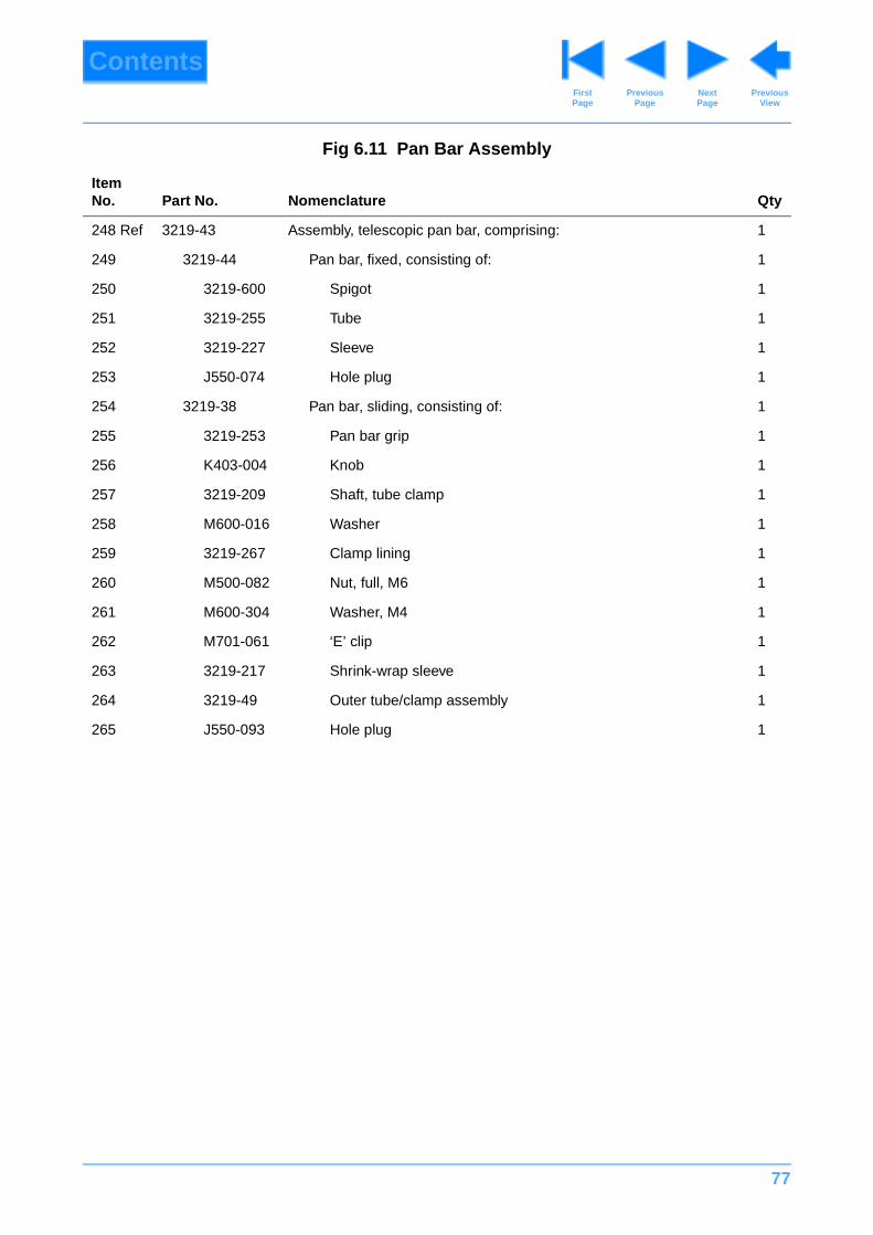
77
ContentsPrevious
PageFirst Page
Next Page
Previous View
Fig 6.11 Pan Bar Assembly
Item No. Part No. Nomenclature Qty
248 Ref 3219-43 Assembly, telescopic pan bar, comprising: 1
249 3219-44 Pan bar, fixed, consisting of: 1
250 3219-600 Spigot 1
251 3219-255 Tube 1
252 3219-227 Sleeve 1
253 J550-074 Hole plug 1
254 3219-38 Pan bar, sliding, consisting of: 1
255 3219-253 Pan bar grip 1
256 K403-004 Knob 1
257 3219-209 Shaft, tube clamp 1
258 M600-016 Washer 1
259 3219-267 Clamp lining 1
260 M500-082 Nut, full, M6 1
261 M600-304 Washer, M4 1
262 M701-061 ‘E’ clip 1
263 3219-217 Shrink-wrap sleeve 1
264 3219-49 Outer tube/clamp assembly 1
265 J550-093 Hole plug 1

78
ContentsPrevious
PageFirst Page
Next Page
Previous View
Fig 6.12 Spherical Base
Fig 6.1Item D
267
274
270
275
271
269
268
V30_6_22
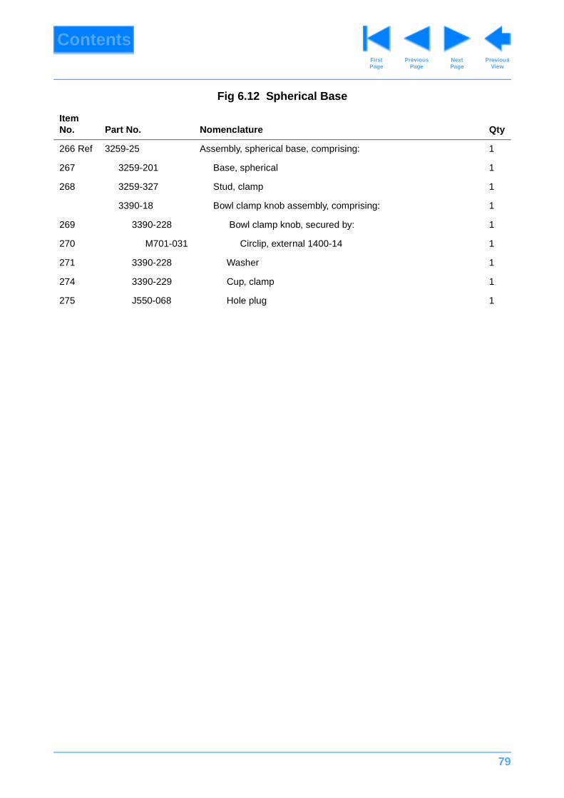
79
ContentsPrevious
PageFirst Page
Next Page
Previous View
Fig 6.12 Spherical Base
Item No. Part No. Nomenclature Qty
266 Ref 3259-25 Assembly, spherical base, comprising: 1
267 3259-201 Base, spherical 1
268 3259-327 Stud, clamp 1
3390-18 Bowl clamp knob assembly, comprising: 1
269 3390-228 Bowl clamp knob, secured by: 1
270 M701-031 Circlip, external 1400-14 1
271 3390-228 Washer 1
274 3390-229 Cup, clamp 1
275 J550-068 Hole plug 1
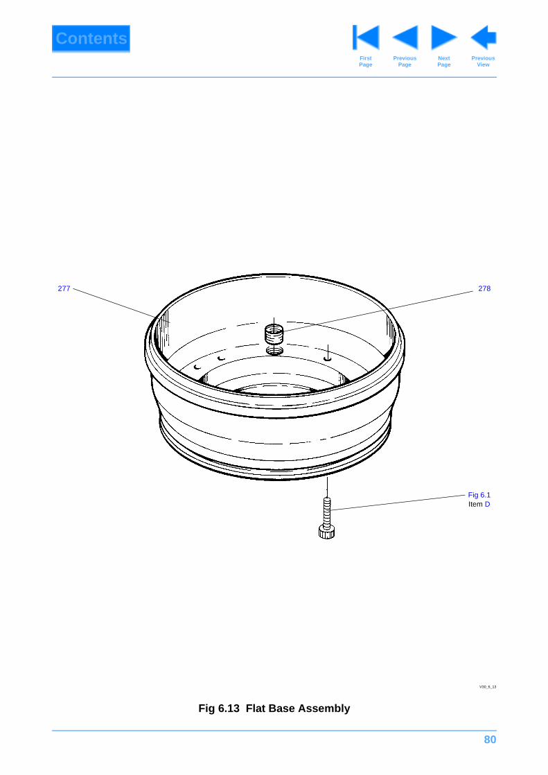
80
ContentsPrevious
PageFirst Page
Next Page
Previous View
Fig 6.13 Flat Base Assembly
278277
Fig 6.1Item D
V30_6_13

81
ContentsPrevious
PageFirst Page
Next Page
Previous View
Fig 6.13 Flat Base Assembly
Item No. Part No. Nomenclature Qty
276 Ref 3259-25 Assembly, flat base, comprising: 1
277 3259-202 Base, Flat 1
278 L850-052 Insert, Helicoil 3/8 in. BSW x 1D 4
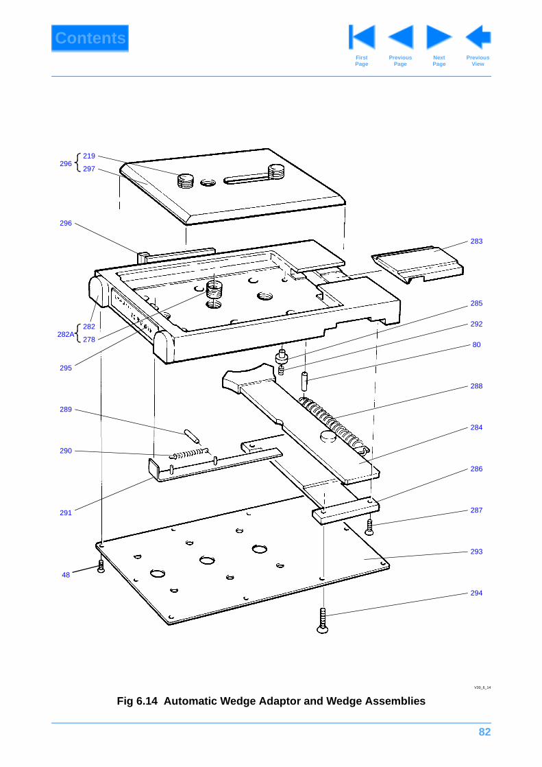
82
ContentsPrevious
PageFirst Page
Next Page
Previous View
Fig 6.14 Automatic Wedge Adaptor and Wedge Assemblies
283
292
285
80
288
284
286
287
293
294
219
297
296
278
295
289
290
291
48
V30_6_14
296
282282A
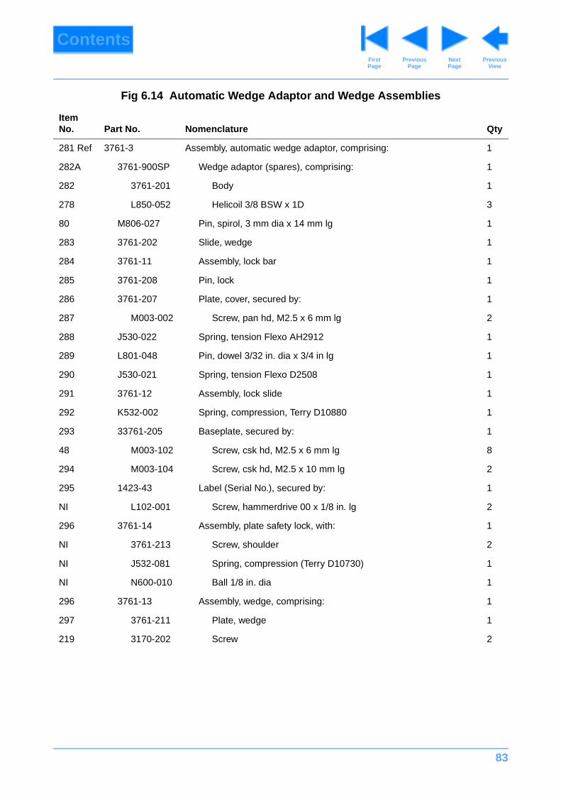
83
ContentsPrevious
PageFirst Page
Next Page
Previous View
Fig 6.14 Automatic Wedge Adaptor and Wedge Assemblies
Item No. Part No. Nomenclature Qty
281 Ref 3761-3 Assembly, automatic wedge adaptor, comprising: 1
282A 3761-900SP Wedge adaptor (spares), comprising: 1
282 3761-201 Body 1
278 L850-052 Helicoil 3/8 BSW x 1D 3
80 M806-027 Pin, spirol, 3 mm dia x 14 mm lg 1
283 3761-202 Slide, wedge 1
284 3761-11 Assembly, lock bar 1
285 3761-208 Pin, lock 1
286 3761-207 Plate, cover, secured by: 1
287 M003-002 Screw, pan hd, M2.5 x 6 mm lg 2
288 J530-022 Spring, tension Flexo AH2912 1
289 L801-048 Pin, dowel 3/32 in. dia x 3/4 in lg 1
290 J530-021 Spring, tension Flexo D2508 1
291 3761-12 Assembly, lock slide 1
292 K532-002 Spring, compression, Terry D10880 1
293 33761-205 Baseplate, secured by: 1
48 M003-102 Screw, csk hd, M2.5 x 6 mm lg 8
294 M003-104 Screw, csk hd, M2.5 x 10 mm lg 2
295 1423-43 Label (Serial No.), secured by: 1
NI L102-001 Screw, hammerdrive 00 x 1/8 in. lg 2
296 3761-14 Assembly, plate safety lock, with: 1
NI 3761-213 Screw, shoulder 2
NI J532-081 Spring, compression (Terry D10730) 1
NI N600-010 Ball 1/8 in. dia 1
296 3761-13 Assembly, wedge, comprising: 1
297 3761-211 Plate, wedge 1
219 3170-202 Screw 2
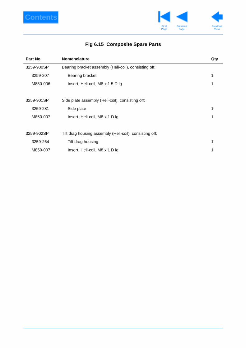
ContentsPrevious
PageFirst Page
Previous View
Fig 6.15 Composite Spare Parts
Part No. Nomenclature Qty
3259-900SP Bearing bracket assembly (Heli-coil), consisting off:
3259-207 Bearing bracket 1
M850-006 Insert, Heli-coil, M8 x 1.5 D lg 1
3259-901SP Side plate assembly (Heli-coil), consisting off:
3259-281 Side plate 1
M850-007 Insert, Heli-coil, M8 x 1 D lg 1
3259-902SP Tilt drag housing assembly (Heli-coil), consisting off:
3259-264 Tilt drag housing 1
M850-007 Insert, Heli-coil, M8 x 1 D lg 1