previous page table of contents next page
TRANSCRIPT
, SERVICE PUBLICATION OFOCKHEED-GEORGIA COMPANY
/ DIVISION OFOCKHEED CORPORATION
Vol. 6, No. 3, July. September 1979
3
15
16
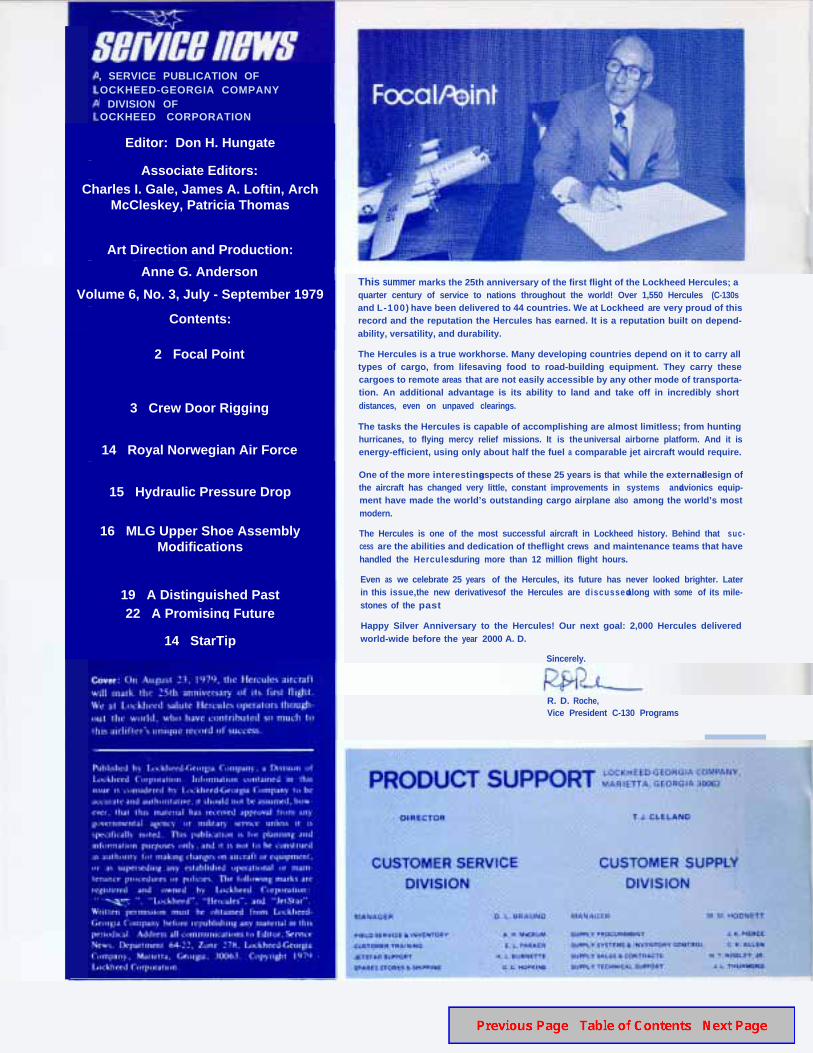
This summer marks the 25th anniversary of the first flight of the Lockheed Hercules; aquarter century of service to nations throughout the world! Over 1,550 Hercules (C-130sand L-100) have been delivered to 44 countries. We at Lockheed are very proud of thisrecord and the reputation the Hercules has earned. It is a reputation built on depend-ability, versatility, and durability.
The Hercules is a true workhorse. Many developing countries depend on it to carry alltypes of cargo, from lifesaving food to road-building equipment. They carry thesecargoes to remote areas that are not easily accessible by any other mode of transporta-tion. An additional advantage is its ability to land and take off in incredibly shortdistances, even on unpaved clearings.
The tasks the Hercules is capable of accomplishing are almost limitless; from huntinghurricanes, to flying mercy relief missions. It is the universal airborne platform. And it isenergy-efficient, using only about half the fuel a comparable jet aircraft would require.
One of the more interesting aspects of these 25 years is that while the external design ofthe aircraft has changed very little, constant improvements in systems and avionics equip-ment have made the world’s outstanding cargo airplane also among the world’s mostmodern.
The Hercules is one of the most successful aircraft in Lockheed history. Behind that suc-cess are the abilities and dedication of theflight crews and maintenance teams that havehandled the Hercules during more than 12 million flight hours.
Even as we celebrate 25 years of the Hercules, its future has never looked brighter. Laterin this issue, the new derivativesof the Hercules are d iscussed along with some of its mile-stones of the past
Happy Silver Anniversary to the Hercules! Our next goal: 2,000 Hercules deliveredworld-wide before the year 2000 A. D.
Sincerely.
R. D. Roche,Vice President C-130 Programs
Editor: Don H. Hungate
Associate Editors:Charles I. Gale, James A. Loftin, Arch
McCleskey, Patricia Thomas
Art Direction and Production:
Anne G. Anderson
Volume 6, No. 3, July - September 1979
Contents:
2 Focal Point
3 Crew Door Rigging
14 Royal Norwegian Air Force
15 Hydraulic Pressure Drop
16 MLG Upper Shoe AssemblyModifications
19 A Distinguished Past22 A Promisin g Future
14 StarTip
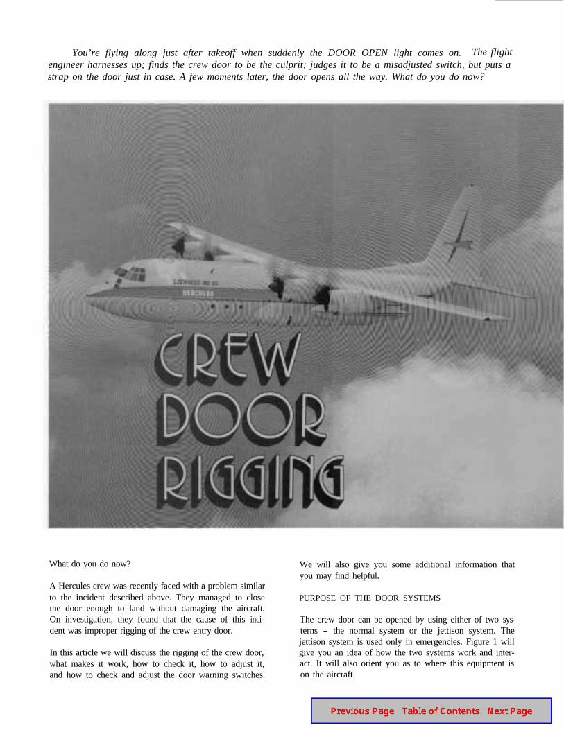
You’re flying along just after takeoff when suddenly the DOOR OPEN light comes on. The flightengineer harnesses up; finds the crew door to be the culprit; judges it to be a misadjusted switch, but puts astrap on the door just in case. A few moments later, the door opens all the way. What do you do now?
What do you do now? We will also give you some additional information thatyou may find helpful.
A Hercules crew was recently faced with a problem similarto the incident described above. They managed to closethe door enough to land without damaging the aircraft.On investigation, they found that the cause of this inci-dent was improper rigging of the crew entry door.
PURPOSE OF THE DOOR SYSTEMS
The crew door can be opened by using either of two sys-terns - the normal system or the jettison system. Thejettison system is used only in emergencies. Figure 1 will
In this article we will discuss the rigging of the crew door, give you an idea of how the two systems work and inter-what makes it work, how to check it, how to adjust it, act. It will also orient you as to where this equipment isand how to check and adjust the door warning switches. on the aircraft.
DOOR CLOSEDSWITCH
4
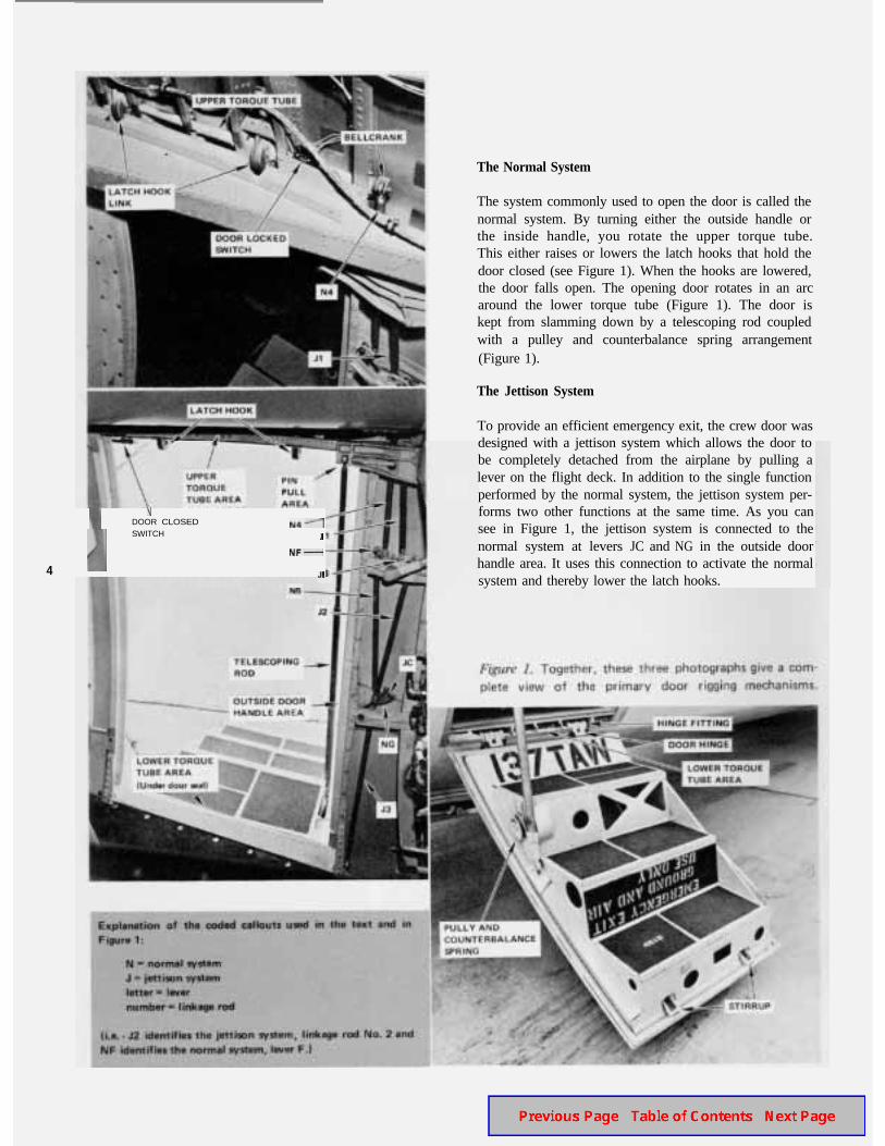
The Normal System
The system commonly used to open the door is called thenormal system. By turning either the outside handle orthe inside handle, you rotate the upper torque tube.This either raises or lowers the latch hooks that hold thedoor closed (see Figure 1). When the hooks are lowered,the door falls open. The opening door rotates in an arcaround the lower torque tube (Figure 1). The door iskept from slamming down by a telescoping rod coupledwith a pulley and counterbalance spring arrangement(Figure 1).
The Jettison System
To provide an efficient emergency exit, the crew door wasdesigned with a jettison system which allows the door tobe completely detached from the airplane by pulling alever on the flight deck. In addition to the single functionperformed by the normal system, the jettison system per-forms two other functions at the same time. As you cansee in Figure 1, the jettison system is connected to thenormal system at levers JC and NG in the outside doorhandle area. It uses this connection to activate the normalsystem and thereby lower the latch hooks.
A second function the jettison system performs is to pullout the pin which holds the telescoping rod, thus releas-ing the rod and its counterbalance system. This is per-formed in the pin pull area (Figure 1).
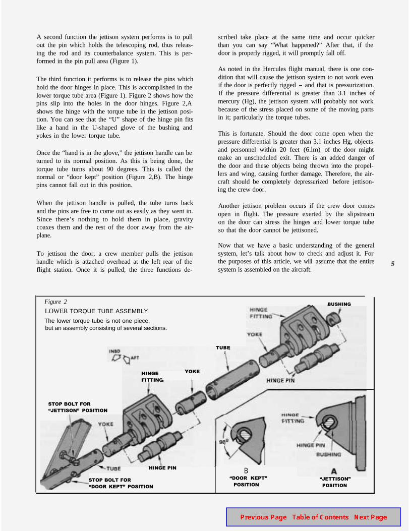
The third function it performs is to release the pins whichhold the door hinges in place. This is accomplished in thelower torque tube area (Figure 1). Figure 2 shows how thepins slip into the holes in the door hinges. Figure 2,Ashows the hinge with the torque tube in the jettison posi-tion. You can see that the “U” shape of the hinge pin fitslike a hand in the U-shaped glove of the bushing andyokes in the lower torque tube.
Once the “hand is in the glove,” the jettison handle can beturned to its normal position. As this is being done, thetorque tube turns about 90 degrees. This is called thenormal or “door kept” position (Figure 2,B). The hingepins cannot fall out in this position.
When the jettison handle is pulled, the tube turns backand the pins are free to come out as easily as they went in.Since there’s nothing to hold them in place, gravitycoaxes them and the rest of the door away from the air-plane.
To jettison the door, a crew member pulls the jettisonhandle which is attached overhead at the left rear of theflight station. Once it is pulled, the three functions de-
scribed take place at the same time and occur quickerthan you can say “What happened?” After that, if thedoor is properly rigged, it will promptly fall off.
As noted in the Hercules flight manual, there is one con-dition that will cause the jettison system to not work evenif the door is perfectly rigged - and that is pressurization.If the pressure differential is greater than 3.1 inches ofmercury (Hg), the jettison system will probably not workbecause of the stress placed on some of the moving partsin it; particularly the torque tubes.
This is fortunate. Should the door come open when thepressure differential is greater than 3.1 inches Hg, objectsand personnel within 20 feet (6.lm) of the door mightmake an unscheduled exit. There is an added danger ofthe door and these objects being thrown into the propel-lers and wing, causing further damage. Therefore, the air-craft should be completely depressurized before jettison-ing the crew door.
Another jettison problem occurs if the crew door comesopen in flight. The pressure exerted by the slipstreamon the door can stress the hinges and lower torque tubeso that the door cannot be jettisoned.
Now that we have a basic understanding of the generalsystem, let’s talk about how to check and adjust it. Forthe purposes of this article, we will assume that the entire system is assembled on the aircraft.
HINGE YOKE
FITTING I
TUBE
Figure 2
LOWER TORQUE TUBE ASSEMBLY
The lower torque tube is not one piece,but an assembly consisting of several sections.
STOP BOLT FOR�JETTISON� POSITION
HINGE PIN
STOP BOLT FOR
�DOOR KEPT� POSITION
BUSHING
B�DOOR KEPT� �JETTISON�
POSITION POSITION
Intermediate
Position BOpen
Position CSTOP
BOLT
LATCH
HOOK
LINK
LATCH HOOK 0.030 INCH MINIMUM
0.055 INCH MAXIMUM I I
OVER CENTER CENTER t
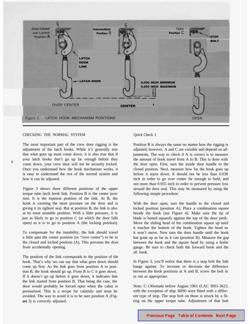
Figure 3. LATCH HOOK MECHANISM POSITIONS OPEN
CHECKING THE NORMAL SYSTEM Quick Check 1
The most important part of the crew door rigging is theadjustment of the latch hooks. While it’s generally truethat what goes up must come down, it is also true that if
6your latch hooks don’t go up far enough before theycome down, your crew door will not be securely locked.Once you understand how the hook mechanism works, itis easy to understand the rest of the normal system andhow it can be adjusted.
Figure 3 shows three different positions of the uppertorque tube latch hook link. Position B is the center posi-tion. It is the topmost position of the link. At B, thehook is exerting the most pressure on the door and isgiving it its tightest seal. But at position B, the link is alsoat its most unstable position. With a little pressure, it isjust as likely to go to position C (at which the door fallsopen) as it is to go to position A (the locking position).
Position B is always the same no matter how the rigging isadjusted; however, A and C are variable and depend on ad-justments. The way to check if A is correct is to measurethe amount of hook travel from A to B. This is done withthe door open. First, turn the inside door handle to theclosed position. Next, measure how far the hook goes upbefore it starts down. It should not be less than 0.030inch in order to go over center far enough to hold, andnot more than 0.055 inch in order to prevent pressure lossaround the door seal. This may be measured by using thefollowing simple procedure:
To compensate for the instability, the link should travela little past the center position (or “over center”) to be inthe closed and locked position (A). This prevents the door from accidentally opening.
With the door open, turn the handle to the closed andlocked position (position A). Place a combination squarebeside the hook (see Figure 4). Make sure the tip ofblade is butted squarely against the top of the door jamb.Move the sliding head of the combination square up untilit touches the bottom of the hook. Tighten the head soit won’t move. Now turn the door handle until the hookhas gone up as far as it can (position B). Measure the gapbetween the hook and the square head by using a feelergauge. Be sure to check both the forward hook and theaft hook.
The position of the link corresponds to the position of thehook. That’s why we can say that what goes down shouldcome up first. As the link goes from position A to posi-tion B, the hook should go up. From B to C it goes down.If it doesn’t go up before it goes down, it indicates thatthe link started from position B. That being the case, thedoor would probably be forced open when the cabin ispressurized. This is a recipe for calamity and must beavoided. The way to avoid it is to be sure position A (Fig-ure 3) is correctly adjusted.
In Figure 3, you’ll notice that there is a stop bolt the linkbangs against. To increase or decrease the differencebetween the hook positions at A and B, screw the bolt inor out as appropriate.
Note: C-130smade before August 1961 (LAC 3001-3623,with the exception of ship 3609) were fitted with a differ-ent type of stop. The stop bolt on these is struck by a fit-ting on the upper torque tube. Adjustment of that bolt
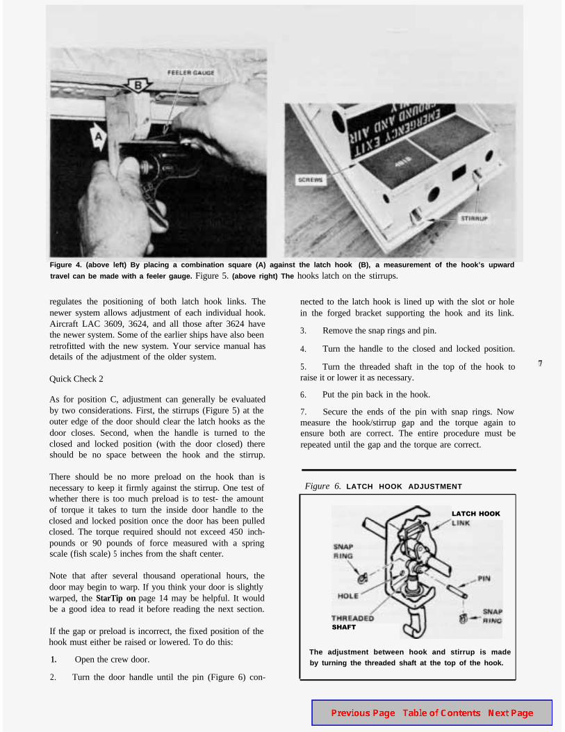
Figure 4. (above left) By placing a combination square (A) against the latch hook (B), a measurement of the hook’s upward
travel can be made with a feeler gauge. Figure 5. (above right) The hooks latch on the stirrups.
regulates the positioning of both latch hook links. Thenewer system allows adjustment of each individual hook.Aircraft LAC 3609, 3624, and all those after 3624 havethe newer system. Some of the earlier ships have also beenretrofitted with the new system. Your service manual hasdetails of the adjustment of the older system.
Quick Check 2
As for position C, adjustment can generally be evaluatedby two considerations. First, the stirrups (Figure 5) at theouter edge of the door should clear the latch hooks as thedoor closes. Second, when the handle is turned to theclosed and locked position (with the door closed) thereshould be no space between the hook and the stirrup.
There should be no more preload on the hook than isnecessary to keep it firmly against the stirrup. One test ofwhether there is too much preload is to test- the amountof torque it takes to turn the inside door handle to theclosed and locked position once the door has been pulledclosed. The torque required should not exceed 450 inch-pounds or 90 pounds of force measured with a springscale (fish scale) 5 inches from the shaft center.
Note that after several thousand operational hours, thedoor may begin to warp. If you think your door is slightlywarped, the StarTip on page 14 may be helpful. It wouldbe a good idea to read it before reading the next section.
If the gap or preload is incorrect, the fixed position of thehook must either be raised or lowered. To do this:
1. Open the crew door.
2. Turn the door handle until the pin (Figure 6) con-
nected to the latch hook is lined up with the slot or holein the forged bracket supporting the hook and its link.
3. Remove the snap rings and pin.
4. Turn the handle to the closed and locked position.
5. Turn the threaded shaft in the top of the hook toraise it or lower it as necessary.
6. Put the pin back in the hook.
7. Secure the ends of the pin with snap rings. Nowmeasure the hook/stirrup gap and the torque again toensure both are correct. The entire procedure must berepeated until the gap and the torque are correct.
Figure 6. LATCH HOOK ADJUSTMENT
LATCH HOOK
SHAFT
The adjustment between hook and stirrup is madeby turning the threaded shaft at the top of the hook.
There are five connecting rods in the general riggingsystem of the crew door - two in the normal system andthree in the jettison system. Each of these rods has anadjustable connection at each end of it.
This allows you great liberty in adjusting the length of therods. This is necessary for ensuring the correct position ofthe levers, handles and bellcranks to which they’re con-nected. It also allows you to remove any slack from thesystem.
Adjustment of the rods is simply a matter of removingthe pins and other fasteners holding them to their cranksor levers, loosening the jamnuts, and then screwing theends in or out to change the length as required. It maybe necessary to adjust both ends to achieve the lengthyou need. Tighten each jamnut to a torque of 48 to 55inch-pounds after fmal adjustment.
Door Handles
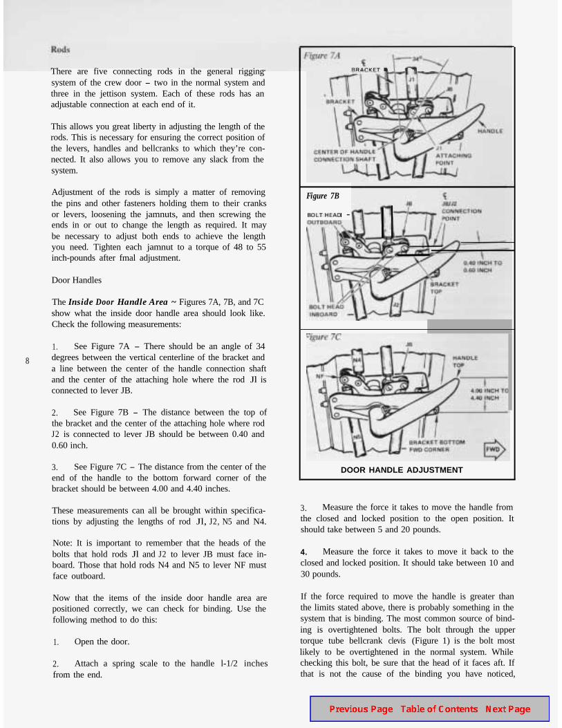
The Inside Door Handle Area ~ Figures 7A, 7B, and 7Cshow what the inside door handle area should look like.Check the following measurements:
1. See Figure 7A - There should be an angle of 34
8 degrees between the vertical centerline of the bracket anda line between the center of the handle connection shaftand the center of the attaching hole where the rod Jl isconnected to lever JB.
2. See Figure 7B - The distance between the top ofthe bracket and the center of the attaching hole where rodJ2 is connected to lever JB should be between 0.40 and0.60 inch.
3. See Figure 7C - The distance from the center of theend of the handle to the bottom forward corner of thebracket should be between 4.00 and 4.40 inches.
These measurements can all be brought within specifica-tions by adjusting the lengths of rod Jl, J2, N5 and N4.
Note: It is important to remember that the heads of thebolts that hold rods Jl and J2 to lever JB must face in-board. Those that hold rods N4 and N5 to lever NF mustface outboard.
Now that the items of the inside door handle area arepositioned correctly, we can check for binding. Use thefollowing method to do this:
1. Open the door.
2. Attach a spring scale to the handle l-1/2 inchesfrom the end.
Figure 7B
-
DOOR HANDLE ADJUSTMENT
3. Measure the force it takes to move the handle fromthe closed and locked position to the open position. Itshould take between 5 and 20 pounds.
4. Measure the force it takes to move it back to theclosed and locked position. It should take between 10 and30 pounds.
If the force required to move the handle is greater thanthe limits stated above, there is probably something in thesystem that is binding. The most common source of bind-ing is overtightened bolts. The bolt through the uppertorque tube bellcrank clevis (Figure 1) is the bolt mostlikely to be overtightened in the normal system. Whilechecking this bolt, be sure that the head of it faces aft. Ifthat is not the cause of the binding you have noticed,
check for bent or otherwise abnormal rods, levers or otherfixtures. Also check to see if something outside thesystem is causing it to bind.
After adjustment, recheck the system to make sure youdo not still exceed the limits of required force statedabove.
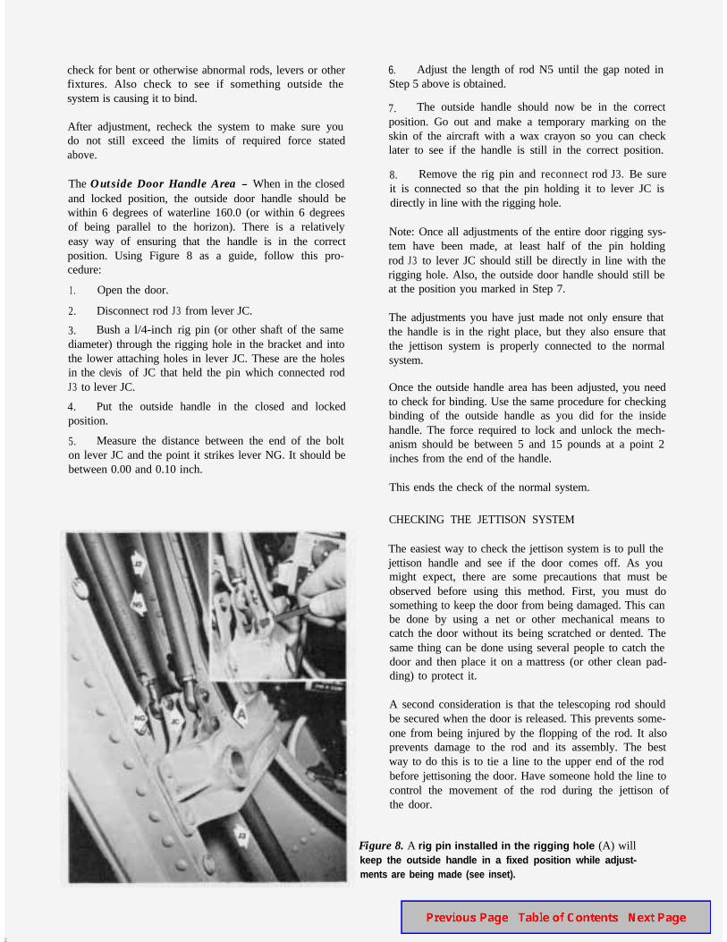
The Outside Door Handle Area - When in the closedand locked position, the outside door handle should bewithin 6 degrees of waterline 160.0 (or within 6 degreesof being parallel to the horizon). There is a relativelyeasy way of ensuring that the handle is in the correctposition. Using Figure 8 as a guide, follow this pro-cedure:
1. Open the door.
2. Disconnect rod J3 from lever JC.
3. Bush a l/4-inch rig pin (or other shaft of the samediameter) through the rigging hole in the bracket and intothe lower attaching holes in lever JC. These are the holesin the clevis of JC that held the pin which connected rodJ3 to lever JC.
4. Put the outside handle in the closed and lockedposition.
5. Measure the distance between the end of the bolton lever JC and the point it strikes lever NG. It should bebetween 0.00 and 0.10 inch.
6. Adjust the length of rod N5 until the gap noted inStep 5 above is obtained.
7. The outside handle should now be in the correctposition. Go out and make a temporary marking on theskin of the aircraft with a wax crayon so you can checklater to see if the handle is still in the correct position.
8. Remove the rig pin and reconnect rod J3. Be sureit is connected so that the pin holding it to lever JC isdirectly in line with the rigging hole.
Note: Once all adjustments of the entire door rigging sys-tem have been made, at least half of the pin holdingrod J3 to lever JC should still be directly in line with therigging hole. Also, the outside door handle should still beat the position you marked in Step 7.
The adjustments you have just made not only ensure thatthe handle is in the right place, but they also ensure thatthe jettison system is properly connected to the normalsystem.
Once the outside handle area has been adjusted, you needto check for binding. Use the same procedure for checkingbinding of the outside handle as you did for the insidehandle. The force required to lock and unlock the mech-anism should be between 5 and 15 pounds at a point 2inches from the end of the handle.
This ends the check of the normal system.
CHECKING THE JETTISON SYSTEM
The easiest way to check the jettison system is to pull thejettison handle and see if the door comes off. As youmight expect, there are some precautions that must beobserved before using this method. First, you must dosomething to keep the door from being damaged. This canbe done by using a net or other mechanical means tocatch the door without its being scratched or dented. Thesame thing can be done using several people to catch thedoor and then place it on a mattress (or other clean pad-ding) to protect it.
A second consideration is that the telescoping rod shouldbe secured when the door is released. This prevents some-one from being injured by the flopping of the rod. It alsoprevents damage to the rod and its assembly. The bestway to do this is to tie a line to the upper end of the rodbefore jettisoning the door. Have someone hold the line tocontrol the movement of the rod during the jettison ofthe door.
Figure 8. A rig pin installed in the rigging hole (A) willkeep the outside handle in a fixed position while adjust-ments are being made (see inset).
Quick Check
The quick check of the jettison system is the procedurejust described. If the door falls off without any problem,the system is probably in proper adjustment. However, ifthe door “bangs” at one or more points, you can readilysee that adjustment in that area is necessary.
Pin-Pull Area
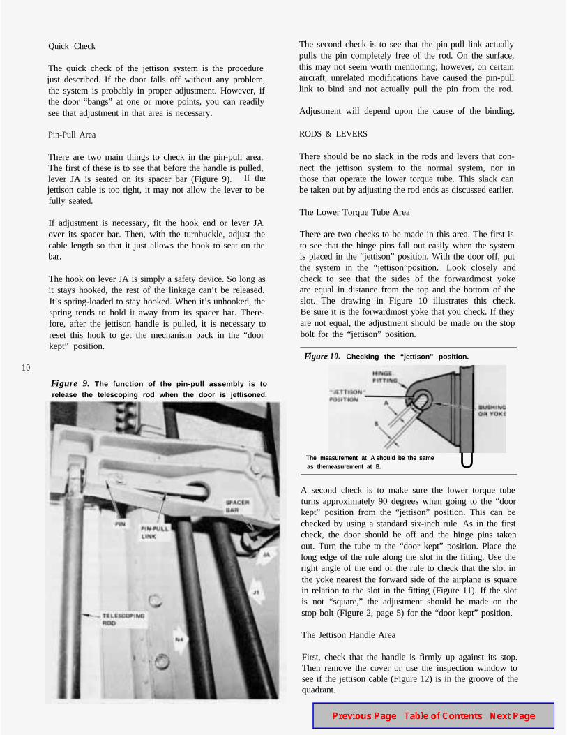
There are two main things to check in the pin-pull area.The first of these is to see that before the handle is pulled,lever JA is seated on its spacer bar (Figure 9).If thejettison cable is too tight, it may not allow the lever to befully seated.
If adjustment is necessary, fit the hook end or lever JAover its spacer bar. Then, with the turnbuckle, adjust thecable length so that it just allows the hook to seat on thebar.
The hook on lever JA is simply a safety device. So long asit stays hooked, the rest of the linkage can’t be released.It’s spring-loaded to stay hooked. When it’s unhooked, thespring tends to hold it away from its spacer bar. There-fore, after the jettison handle is pulled, it is necessary toreset this hook to get the mechanism back in the “doorkept” position.
10
Figure 9. The function of the pin-pull assembly is torelease the telescoping rod when the door is jettisoned.
The second check is to see that the pin-pull link actuallypulls the pin completely free of the rod. On the surface,this may not seem worth mentioning; however, on certainaircraft, unrelated modifications have caused the pin-pulllink to bind and not actually pull the pin from the rod.
Adjustment will depend upon the cause of the binding.
RODS & LEVERS
There should be no slack in the rods and levers that con-nect the jettison system to the normal system, nor inthose that operate the lower torque tube. This slack canbe taken out by adjusting the rod ends as discussed earlier.
The Lower Torque Tube Area
There are two checks to be made in this area. The first isto see that the hinge pins fall out easily when the systemis placed in the “jettison” position. With the door off, putthe system in the “jettison”position. Look closely andcheck to see that the sides of the forwardmost yokeare equal in distance from the top and the bottom of theslot. The drawing in Figure 10 illustrates this check.Be sure it is the forwardmost yoke that you check. If theyare not equal, the adjustment should be made on the stopbolt for the “jettison” position.
Figure 10. Checking the “jettison” position.
The measurement at A should be the sameas themeasurement at B. U
A second check is to make sure the lower torque tubeturns approximately 90 degrees when going to the “doorkept” position from the “jettison” position. This can bechecked by using a standard six-inch rule. As in the firstcheck, the door should be off and the hinge pins takenout. Turn the tube to the “door kept” position. Place thelong edge of the rule along the slot in the fitting. Use theright angle of the end of the rule to check that the slot inthe yoke nearest the forward side of the airplane is squarein relation to the slot in the fitting (Figure 11). If the slotis not “square,” the adjustment should be made on thestop bolt (Figure 2, page 5) for the “door kept” position.
The Jettison Handle Area
First, check that the handle is firmly up against its stop.Then remove the cover or use the inspection window tosee if the jettison cable (Figure 12) is in the groove of thequadrant.
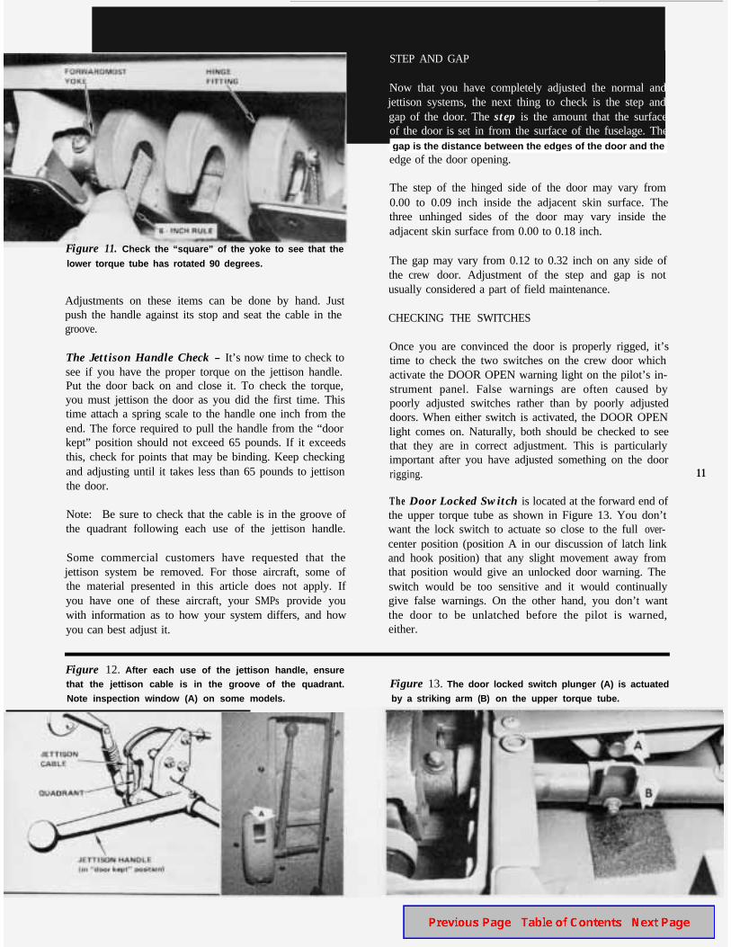
Figure 11. Check the “square” of the yoke to see that the
lower torque tube has rotated 90 degrees.
Adjustments on these items can be done by hand. Justpush the handle against its stop and seat the cable in thegroove.
The Jettison Handle Check - It’s now time to check tosee if you have the proper torque on the jettison handle.Put the door back on and close it. To check the torque,you must jettison the door as you did the first time. Thistime attach a spring scale to the handle one inch from theend. The force required to pull the handle from the “doorkept” position should not exceed 65 pounds. If it exceedsthis, check for points that may be binding. Keep checkingand adjusting until it takes less than 65 pounds to jettisonthe door.
Note: Be sure to check that the cable is in the groove ofthe quadrant following each use of the jettison handle.
Some commercial customers have requested that thejettison system be removed. For those aircraft, some ofthe material presented in this article does not apply. Ifyou have one of these aircraft, your SMPs provide youwith information as to how your system differs, and howyou can best adjust it.
STEP AND GAP
Now that you have completely adjusted the normal andjettison systems, the next thing to check is the step andgap of the door. The step is the amount that the surfaceof the door is set in from the surface of the fuselage. Thegap is the distance between the edges of the door and theedge of the door opening.
The step of the hinged side of the door may vary from0.00 to 0.09 inch inside the adjacent skin surface. Thethree unhinged sides of the door may vary inside theadjacent skin surface from 0.00 to 0.18 inch.
The gap may vary from 0.12 to 0.32 inch on any side ofthe crew door. Adjustment of the step and gap is notusually considered a part of field maintenance.
CHECKING THE SWITCHES
Once you are convinced the door is properly rigged, it’stime to check the two switches on the crew door whichactivate the DOOR OPEN warning light on the pilot’s in-strument panel. False warnings are often caused bypoorly adjusted switches rather than by poorly adjusteddoors. When either switch is activated, the DOOR OPENlight comes on. Naturally, both should be checked to seethat they are in correct adjustment. This is particularlyimportant after you have adjusted something on the doorrigging. 11
The Door Locked Switch is located at the forward end ofthe upper torque tube as shown in Figure 13. You don’twant the lock switch to actuate so close to the full over-center position (position A in our discussion of latch linkand hook position) that any slight movement away fromthat position would give an unlocked door warning. Theswitch would be too sensitive and it would continuallygive false warnings. On the other hand, you don’t wantthe door to be unlatched before the pilot is warned,either.
Figure 12. After each use of the jettison handle, ensurethat the jettison cable is in the groove of the quadrant.
Note inspection window (A) on some models.
Figure 13. The door locked switch plunger (A) is actuated
by a striking arm (B) on the upper torque tube.
gap is the distance between the edges of the door and the
12
Figure 14. The door closed switch is located near
upper aft corner of the door opening.
the
The proper adjustment is for the switch to actuate half-way between the full overcenter position (position A) andthe center position (position B). With the door open, pullthe inside door handle back from the closed position.Watch the latch hooks. When they get to position B, stop.Look at and mark the position of the inside door handlewith a wax marker. Don’t forget to compensate for anyslack in the system. Listen carefully for the “click” theswitch makes as it actuates. You should hear the “click”at a point halfway between the position the handle is inwhen the hook starts to move up and the place youmarked as position B.
To double-check the “click,” you can have someonewatch for the DOOR OPEN light to come on and reportto you when it does. Another double check of the systemis to measure the amount of overtravel in the switch.There should be an overtravel of 0.03 to 0.05 inch. Ifadjustment of the switch is necessary, use the lock nutson the switch at the point where the plunger enters it.
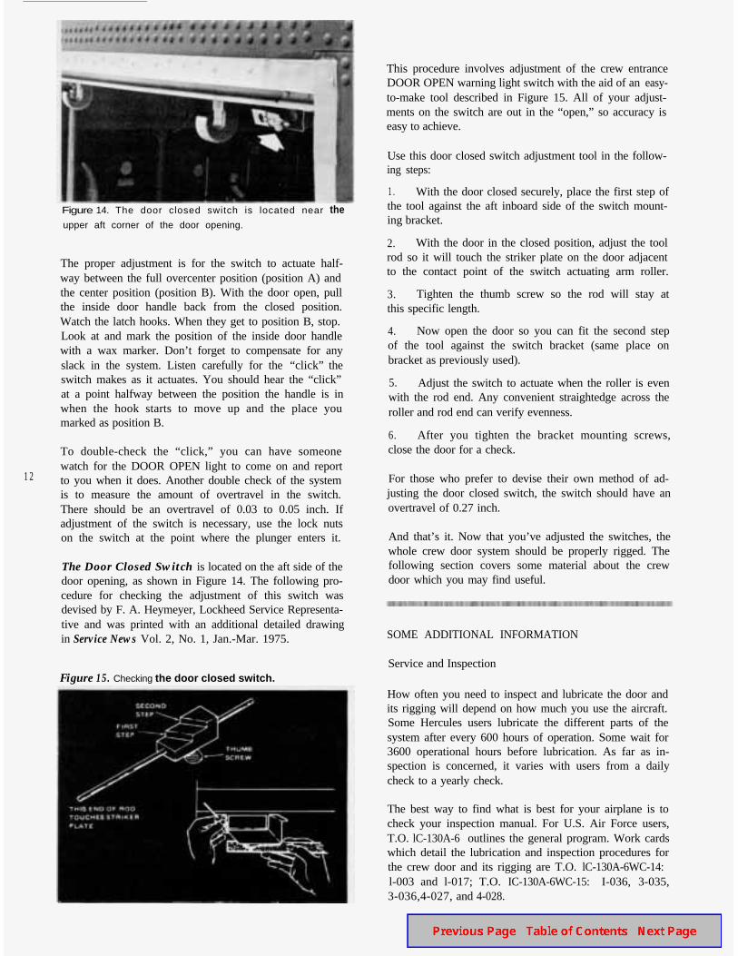
The Door Closed Switch is located on the aft side of thedoor opening, as shown in Figure 14. The following pro-cedure for checking the adjustment of this switch wasdevised by F. A. Heymeyer, Lockheed Service Representa-tive and was printed with an additional detailed drawingin Service News Vol. 2, No. 1, Jan.-Mar. 1975.
Figure 15 . Checking the door closed switch.
This procedure involves adjustment of the crew entranceDOOR OPEN warning light switch with the aid of an easy-to-make tool described in Figure 15. All of your adjust-ments on the switch are out in the “open,” so accuracy iseasy to achieve.
Use this door closed switch adjustment tool in the follow-ing steps:
1. With the door closed securely, place the first step ofthe tool against the aft inboard side of the switch mount-ing bracket.
2. With the door in the closed position, adjust the toolrod so it will touch the striker plate on the door adjacentto the contact point of the switch actuating arm roller.
3. Tighten the thumb screw so the rod will stay atthis specific length.
4. Now open the door so you can fit the second stepof the tool against the switch bracket (same place onbracket as previously used).
5. Adjust the switch to actuate when the roller is evenwith the rod end. Any convenient straightedge across theroller and rod end can verify evenness.
6. After you tighten the bracket mounting screws,close the door for a check.
For those who prefer to devise their own method of ad-justing the door closed switch, the switch should have anovertravel of 0.27 inch.
And that’s it. Now that you’ve adjusted the switches, thewhole crew door system should be properly rigged. Thefollowing section covers some material about the crewdoor which you may find useful.
SOME ADDITIONAL INFORMATION
Service and Inspection
How often you need to inspect and lubricate the door andits rigging will depend on how much you use the aircraft.Some Hercules users lubricate the different parts of thesystem after every 600 hours of operation. Some wait for3600 operational hours before lubrication. As far as in-spection is concerned, it varies with users from a dailycheck to a yearly check.
The best way to find what is best for your airplane is tocheck your inspection manual. For U.S. Air Force users,T.O. lC-130A-6 outlines the general program. Work cardswhich detail the lubrication and inspection procedures forthe crew door and its rigging are T.O. lC-130A-6WC-14:l-003 and l-017; T.O. IC-130A-6WC-15: I-036, 3-035,3-036,4-027, and 4-028.
For other Hercules users, the schedule for lubrication andinspection of your door and its rigging is outlined inSMP 515, SMP 515C or your own organization’s mainte-nance manual, depending on the program of maintenanceyou use. Your schedule of maintenance has been tailoredto your needs as determined by how often you use theaircraft and by the climate in which you primarily oper-ate.
The “Loose” Door
It has been reported that a few flights have been cancelledbecause the crew door was determined to be “loose” andtherefore not airworthy. To check the airworthiness ofthe door, a crew member had stepped out of the planeduring the preflight inspection. He had then grabbed theopen crew door and begun to shake it, cocking it fore andaft to check it for looseness. A Lockheed structural engi-neer evaluated this“check” as about as effective askicking the tires.
The most effective check of the crew door rigging is tocheck the overcenter position of the latch hook links andto check the gaps between the latch hooks and the stir-rups. Cocking the door fore and aft geometrically multi-plies the natural tolerances between the hinges and thepins, and adds them to natural stress tolerances built intothe door itself,
A more effective quick check of the “looseness” of theitems in the door hinge area is to open the door, grab it atits outside edges and then push it toward the fuselage andpull it back again. If this push-pull variance is over 0.04inch, the hinge area should probably be checked at thenext maintenance inspection. But it is still very airworthy.
Door pins do get loose. Sometimes they need replace-ment. Here are some tolerances you can use to checkthem:
l Diameter of the hole into which the hinge pins fit -0.878 inch maximum.
l Outside diameter of the part of the pm which fitsinto the hinge - 0.868 inch minimum.
Closing the Crew Door in Flight
In the unlikely event that the crew door should open inflight, it is a good idea to know how to close it. The fol-lowing procedure is recommended:
1. Be sure the person near the door is wearing a safetyharness.
2. Get an MC-l tiedown strap.
3. Adjust the strap so that the takeup assembly isabout 3 feet (1 m) from one end of the strap.
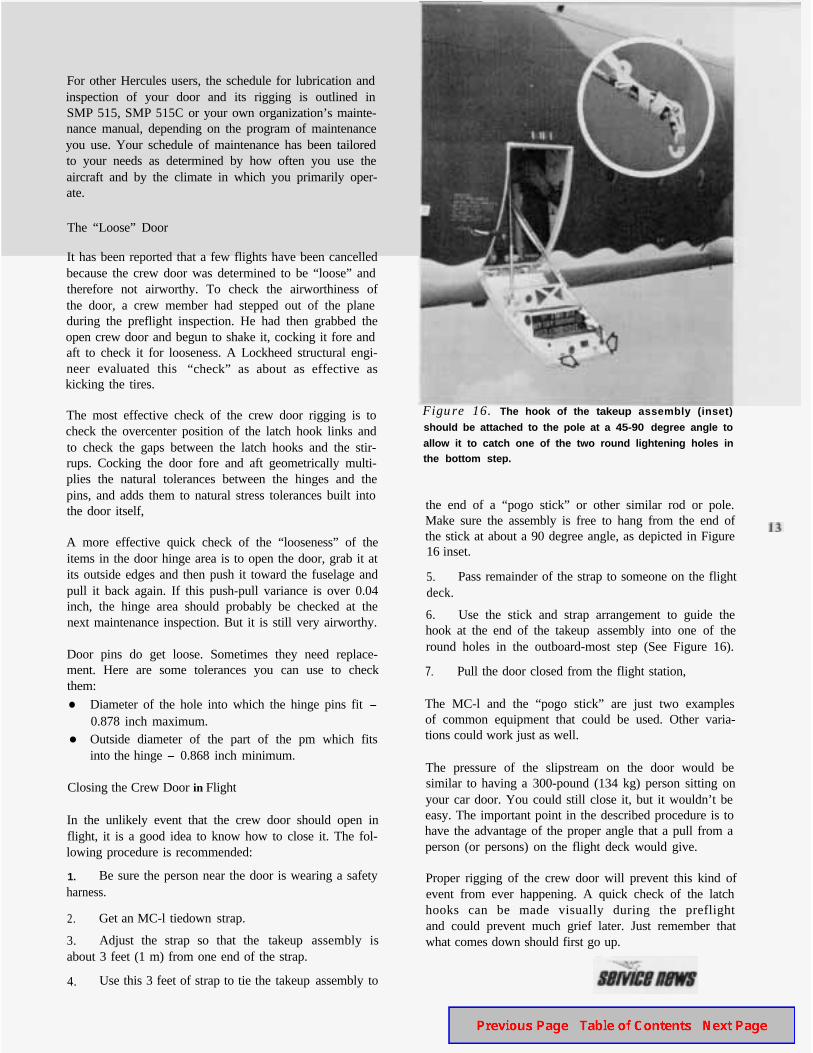
4. Use this 3 feet of strap to tie the takeup assembly to
Figure 16. The hook of the takeup assembly (inset)
should be attached to the pole at a 45-90 degree angle to
allow it to catch one of the two round lightening holes inthe bottom step.
the end of a “pogo stick” or other similar rod or pole.Make sure the assembly is free to hang from the end ofthe stick at about a 90 degree angle, as depicted in Figure16 inset.
5. Pass remainder of the strap to someone on the flightdeck.
6. Use the stick and strap arrangement to guide thehook at the end of the takeup assembly into one of theround holes in the outboard-most step (See Figure 16).
7. Pull the door closed from the flight station,
The MC-l and the “pogo stick” are just two examplesof common equipment that could be used. Other varia-tions could work just as well.
The pressure of the slipstream on the door would besimilar to having a 300-pound (134 kg) person sitting onyour car door. You could still close it, but it wouldn’t beeasy. The important point in the described procedure is tohave the advantage of the proper angle that a pull from aperson (or persons) on the flight deck would give.
Proper rigging of the crew door will prevent this kind ofevent from ever happening. A quick check of the latchhooks can be made visually during the preflightand could prevent much grief later. Just remember thatwhat comes down should first go up.
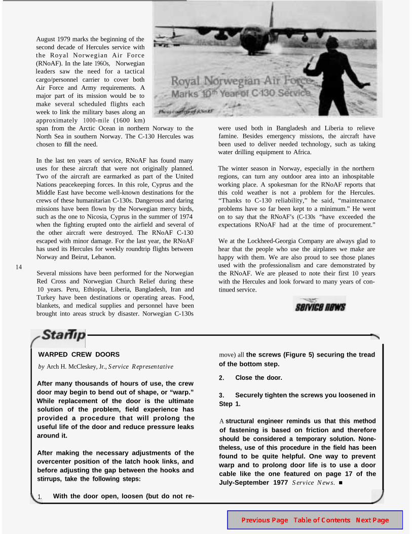
August 1979 marks the beginning of thesecond decade of Hercules service withthe Royal Norwegian Air Force(RNoAF). In the late 196Os, Norwegianleaders saw the need for a tacticalcargo/personnel carrier to cover bothAir Force and Army requirements. Amajor part of its mission would be tomake several scheduled flights eachweek to link the military bases along anapproximately 1000-mile (1600 km)span from the Arctic Ocean in northern Norway to theNorth Sea in southern Norway. The C-130 Hercules waschosen to fill the need.
14
In the last ten years of service, RNoAF has found manyuses for these aircraft that were not originally planned.Two of the aircraft are earmarked as part of the UnitedNations peacekeeping forces. In this role, Cyprus and theMiddle East have become well-known destinations for thecrews of these humanitarian C-130s. Dangerous and daringmissions have been flown by the Norwegian mercy birds,such as the one to Nicosia, Cyprus in the summer of 1974when the fighting erupted onto the airfield and several ofthe other aircraft were destroyed. The RNoAF C-130escaped with minor damage. For the last year, the RNoAFhas used its Hercules for weekly roundtrip flights betweenNorway and Beirut, Lebanon.
Several missions have been performed for the NorwegianRed Cross and Norwegian Church Relief during these10 years. Peru, Ethiopia, Liberia, Bangladesh, Iran andTurkey have been destinations or operating areas. Food,blankets, and medical supplies and personnel have beenbrought into areas struck by disaster. Norwegian C-130s
were used both in Bangladesh and Liberia to relievefamine. Besides emergency missions, the aircraft havebeen used to deliver needed technology, such as takingwater drilling equipment to Africa.
The winter season in Norway, especially in the northernregions, can turn any outdoor area into an inhospitableworking place. A spokesman for the RNoAF reports thatthis cold weather is not a problem for the Hercules.“Thanks to C-130 reliability,” he said, “maintenanceproblems have so far been kept to a minimum.” He wenton to say that the RNoAF’s (C-130s “have exceeded theexpectations RNoAF had at the time of procurement.”
We at the Lockheed-Georgia Company are always glad tohear that the people who use the airplanes we make arehappy with them. We are also proud to see those planesused with the professionalism and care demonstrated bythe RNoAF. We are pleased to note their first 10 yearswith the Hercules and look forward to many years of con-tinued service.
WARPED CREW DOORS
by Arch H. McCleskey, Jr., Service Representative
After many thousands of hours of use, the crewdoor may begin to bend out of shape, or “warp.”While replacement of the door is the ultimatesolution of the problem, field experience hasprovided a procedure that will prolong theuseful life of the door and reduce pressure leaksaround it.
After making the necessary adjustments of theovercenter position of the latch hook links, andbefore adjusting the gap between the hooks andstirrups, take the following steps:
1. With the door open, loosen (but do not re-
move) all the screws (Figure 5) securing the treadof the bottom step.
2. Close the door.
3. Securely tighten the screws you loosened inStep 1.
A structural engineer reminds us that this methodof fastening is based on friction and thereforeshould be considered a temporary solution. None-theless, use of this procedure in the field has beenfound to be quite helpful. One way to preventwarp and to prolong door life is to use a doorcable like the one featured on page 17 of theJuly-September 1977 Service News. n
by John Walters, Research/Design andDevelopment Engineer Associate
Normal actuation of the main landing gear uses hydraulicpower from the utility hydraulic system. During thisactuation, a pressure drop may be noted on the hydraulicpressure gauge for the utility system. Some operatorshave indicated concern about the minimum acceptable hy-draulic pressure reading.
Under certain circumstances, an acceptable pressurereading can be as low as 1500 psi. Many are surprised withthis low figure, but first let us explain how such a lowreading could occur in a normal operating situation.
There are several different flow regulator configurationsand three pump configurations that may be used on theHercules, and these various configurations can affect theminimum pressure reading during landing gear actuation.
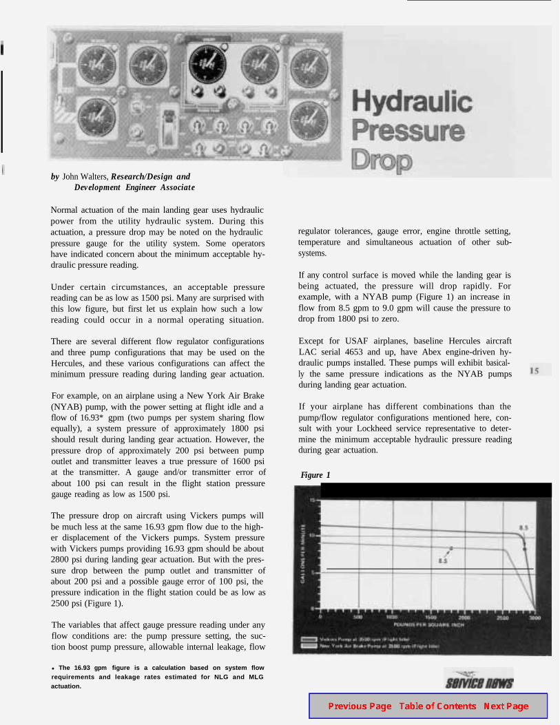
For example, on an airplane using a New York Air Brake(NYAB) pump, with the power setting at flight idle and aflow of 16.93* gpm (two pumps per system sharing flowequally), a system pressure of approximately 1800 psishould result during landing gear actuation. However, thepressure drop of approximately 200 psi between pumpoutlet and transmitter leaves a true pressure of 1600 psiat the transmitter. A gauge and/or transmitter error ofabout 100 psi can result in the flight station pressuregauge reading as low as 1500 psi.
The pressure drop on aircraft using Vickers pumps willbe much less at the same 16.93 gpm flow due to the high-er displacement of the Vickers pumps. System pressurewith Vickers pumps providing 16.93 gpm should be about2800 psi during landing gear actuation. But with the pres-sure drop between the pump outlet and transmitter ofabout 200 psi and a possible gauge error of 100 psi, thepressure indication in the flight station could be as low as2500 psi (Figure 1).
The variables that affect gauge pressure reading under anyflow conditions are: the pump pressure setting, the suc-tion boost pump pressure, allowable internal leakage, flow
l The 16.93 gpm figure is a calculation based on system flowrequirements and leakage rates estimated for NLG and MLGactuation.
regulator tolerances, gauge error, engine throttle setting,temperature and simultaneous actuation of other sub-systems.
If any control surface is moved while the landing gear isbeing actuated, the pressure will drop rapidly. Forexample, with a NYAB pump (Figure 1) an increase inflow from 8.5 gpm to 9.0 gpm will cause the pressure todrop from 1800 psi to zero.
Except for USAF airplanes, baseline Hercules aircraftLAC serial 4653 and up, have Abex engine-driven hy-draulic pumps installed. These pumps will exhibit basical-ly the same pressure indications as the NYAB pumpsduring landing gear actuation.
If your airplane has different combinations than thepump/flow regulator configurations mentioned here, con-sult with your Lockheed service representative to deter-mine the minimum acceptable hydraulic pressure readingduring gear actuation.
Figure 1
by C. R. Bush, Design Engineer Specialist
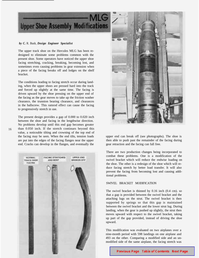
The upper track shoe on the Hercules MLG has been re-designed to eliminate some problems common with thepresent shoe. Some operators have noticed the upper shoefacing stretching, cracking, breaking, becoming lost, andsometimes even causing problems in gear extension whena piece of the facing breaks off and lodges on the shelfbracket.
The conditions leading to facing stretch occur during land-ing, when the upper shoes are pressed hard into the trackand forced up slightly at the same time. The facing isdriven upward by the shoe pressing on the upper end ofthe facing as the gear moves to take up the friction washerclearance, the trunnion bearing clearance, and clearancesin the ballscrew. This ramrod effect can cause the facingto progressively stretch in use.
16
The present design provides a gap of 0.000 to 0.020 inchbetween the shoe and facing in the lengthwise direction.No problems develop until this end gap becomes greaterthan 0.050 inch. If the stretch continues beyond thisvalue, a noticeable tilting and crowning of the top end ofthe facing may be seen. When the end tilts, tension loadsare put into the edges of the facing flanges near the upperend. Cracks can develop in the flanges, and eventually the
upper end can break off (see photographs). The shoe isthen able to push past the remainder of the facing duringgear retraction and the facing can fall free.
There are two production changes being incorporated tocombat these problems. One is a modification of theswivel bracket which will reduce the endwise loading onthe shoe. The other is a redesign of the shoe which will re-duce facing stretch by better load transfer. It will alsoprevent the facing from becoming lost and causing addi-tional problems.
SWIVEL BRACKET MODIFICATION
The swivel bracket is thinned by 0.16 inch (0.4 cm). sothat a gap is provided between the swivel bracket and theattaching lugs on the strut. The swivel bracket is thensupported by springs so that this gap is maintainedbetween the swivel bracket and the lower strut lug. Duringlanding, when the gear is pushed up slightly, the strut thenmoves upward with respect to the swivel bracket, takingup part of the gap provided, instead of driving the shoeupward.
This modification was evaluated on two airplanes over anine-month period with 598 landings on one airplane and493 on the other. Comparing a modified side and an un-modified side of the same airplane, the facing stretch was
reduced by 53 percent and 55 percent respectively onthese two airplanes.
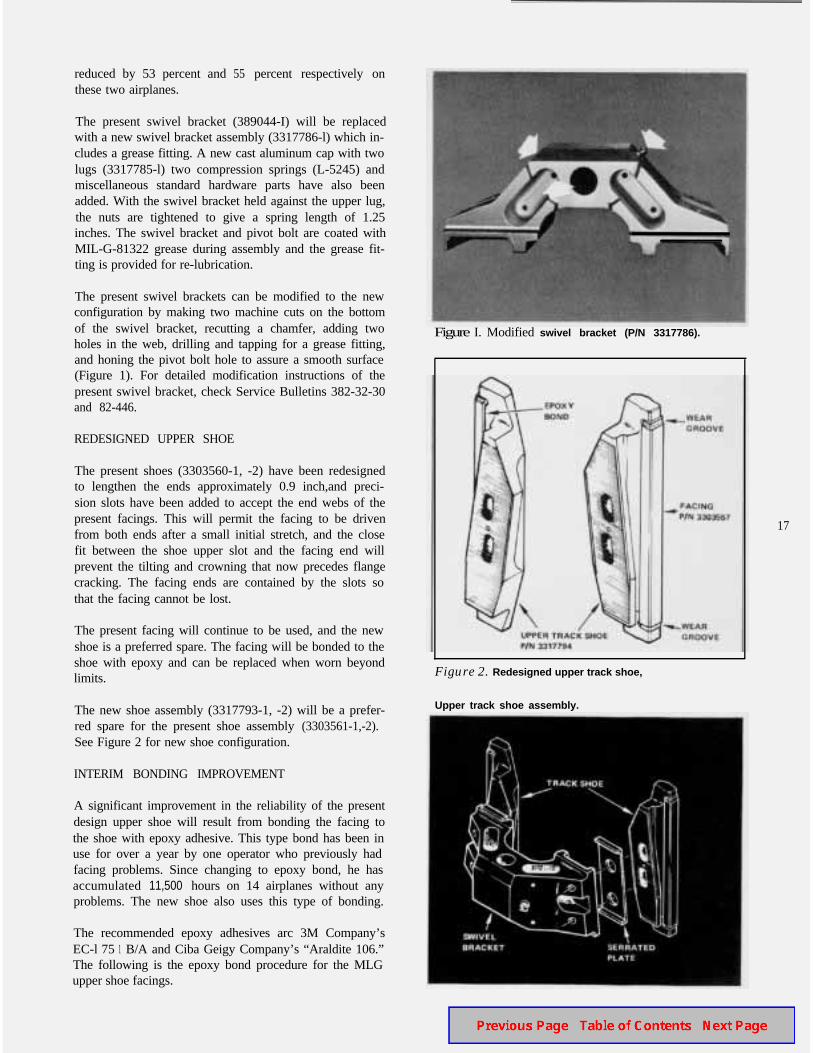
The present swivel bracket (389044-I) will be replacedwith a new swivel bracket assembly (3317786-l) which in-cludes a grease fitting. A new cast aluminum cap with twolugs (3317785-l) two compression springs (L-5245) andmiscellaneous standard hardware parts have also beenadded. With the swivel bracket held against the upper lug,the nuts are tightened to give a spring length of 1.25inches. The swivel bracket and pivot bolt are coated withMIL-G-81322 grease during assembly and the grease fit-ting is provided for re-lubrication.
The present swivel brackets can be modified to the newconfiguration by making two machine cuts on the bottomof the swivel bracket, recutting a chamfer, adding twoholes in the web, drilling and tapping for a grease fitting,and honing the pivot bolt hole to assure a smooth surface(Figure 1). For detailed modification instructions of thepresent swivel bracket, check Service Bulletins 382-32-30and 82-446.
REDESIGNED UPPER SHOE
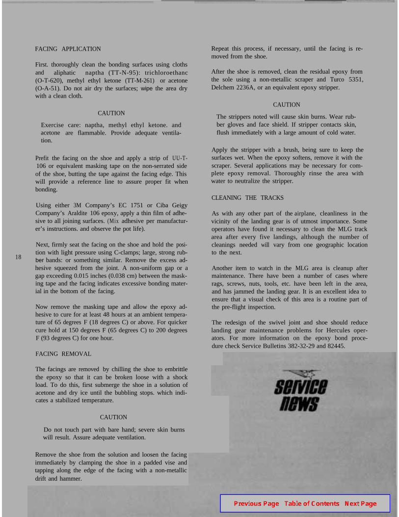
The present shoes (3303560-1, -2) have been redesignedto lengthen the ends approximately 0.9 inch,and preci-sion slots have been added to accept the end webs of thepresent facings. This will permit the facing to be drivenfrom both ends after a small initial stretch, and the closefit between the shoe upper slot and the facing end willprevent the tilting and crowning that now precedes flangecracking. The facing ends are contained by the slots sothat the facing cannot be lost.
The present facing will continue to be used, and the newshoe is a preferred spare. The facing will be bonded to theshoe with epoxy and can be replaced when worn beyondlimits.
The new shoe assembly (3317793-1, -2) will be a prefer-red spare for the present shoe assembly (3303561-1,-2).See Figure 2 for new shoe configuration.
INTERIM BONDING IMPROVEMENT
A significant improvement in the reliability of the presentdesign upper shoe will result from bonding the facing tothe shoe with epoxy adhesive. This type bond has been inuse for over a year by one operator who previously hadfacing problems. Since changing to epoxy bond, he hasaccumulated 11,500 hours on 14 airplanes without anyproblems. The new shoe also uses this type of bonding.
The recommended epoxy adhesives arc 3M Company’sEC-l 75 1 B/A and Ciba Geigy Company’s “Araldite 106.”The following is the epoxy bond procedure for the MLGupper shoe facings.
Figure I. Modified swivel bracket (P/N 3317786).
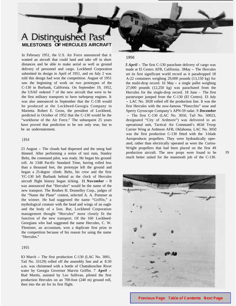
Figure 2. Redesigned upper track shoe,
Upper track shoe assembly.
17
FACING APPLICATION
First. thoroughly clean the bonding surfaces using clothsand aliphatic naptha (TT-N-95): trichloroethanc(O-T-620), methyl ethyl ketone (TT-M-261) or acetone(O-A-51). Do not air dry the surfaces; wipe the area drywith a clean cloth.
CAUTION
Exercise care: naptha, methyl ethyl ketone. andacetone are flammable. Provide adequate ventila-tion.
Prefit the facing on the shoe and apply a strip of UU-T-106 or equivalent masking tape on the non-serrated sideof the shoe, butting the tape against the facing edge. Thiswill provide a reference line to assure proper fit whenbonding.
Using either 3M Company’s EC 1751 or Ciba GeigyCompany’s Araldite 106 epoxy, apply a thin film of adhe-sive to all joining surfaces. (Mix adhesive per manufactur-er’s instructions. and observe the pot life).
18
Next, firmly seat the facing on the shoe and hold the posi-tion with light pressure using C-clamps; large, strong rub-ber bands: or something similar. Remove the excess ad-hesive squeezed from the joint. A non-uniform gap or agap exceeding 0.015 inches (0.038 cm) between the mask-ing tape and the facing indicates excessive bonding mater-ial in the bottom of the facing.
Now remove the masking tape and allow the epoxy ad-hesive to cure for at least 48 hours at an ambient tempera-ture of 65 degrees F (18 degrees C) or above. For quickercure hold at 150 degrees F (65 degrees C) to 200 degreesF (93 degrees C) for one hour.
FACING REMOVAL
The facings are removed by chilling the shoe to embrittlethe epoxy so that it can be broken loose with a shockload. To do this, first submerge the shoe in a solution ofacetone and dry ice until the bubbling stops. which indi-cates a stabilized temperature.
CAUTION
Do not touch part with bare hand; severe skin burnswill result. Assure adequate ventilation.
Remove the shoe from the solution and loosen the facingimmediately by clamping the shoe in a padded vise andtapping along the edge of the facing with a non-metallicdrift and hammer.
Repeat this process, if necessary, until the facing is re-moved from the shoe.
After the shoe is removed, clean the residual epoxy fromthe sole using a non-metallic scraper and Turco 5351,Delchem 2236A, or an equivalent epoxy stripper.
CAUTION
The strippers noted will cause skin burns. Wear rub-ber gloves and face shield. If stripper contacts skin,flush immediately with a large amount of cold water.
Apply the stripper with a brush, being sure to keep thesurfaces wet. When the epoxy softens, remove it with thescraper. Several applications may be necessary for com-plete epoxy removal. Thoroughly rinse the area withwater to neutralize the stripper.
CLEANING THE TRACKS
As with any other part of the airplane, cleanliness in thevicinity of the landing gear is of utmost importance. Someoperators have found it necessary to clean the MLG trackarea after every five landings, although the number ofcleanings needed will vary from one geographic locationto the next.
Another item to watch in the MLG area is cleanup aftermaintenance. There have been a number of cases whererags, screws, nuts, tools, etc. have been left in the area,and has jammed the landing gear. It is an excellent idea toensure that a visual check of this area is a routine part ofthe pre-flight inspection.
The redesign of the swivel joint and shoe should reducelanding gear maintenance problems for Hercules oper-ators. For more information on the epoxy bond proce-dure check Service Bulletins 382-32-29 and 82445.
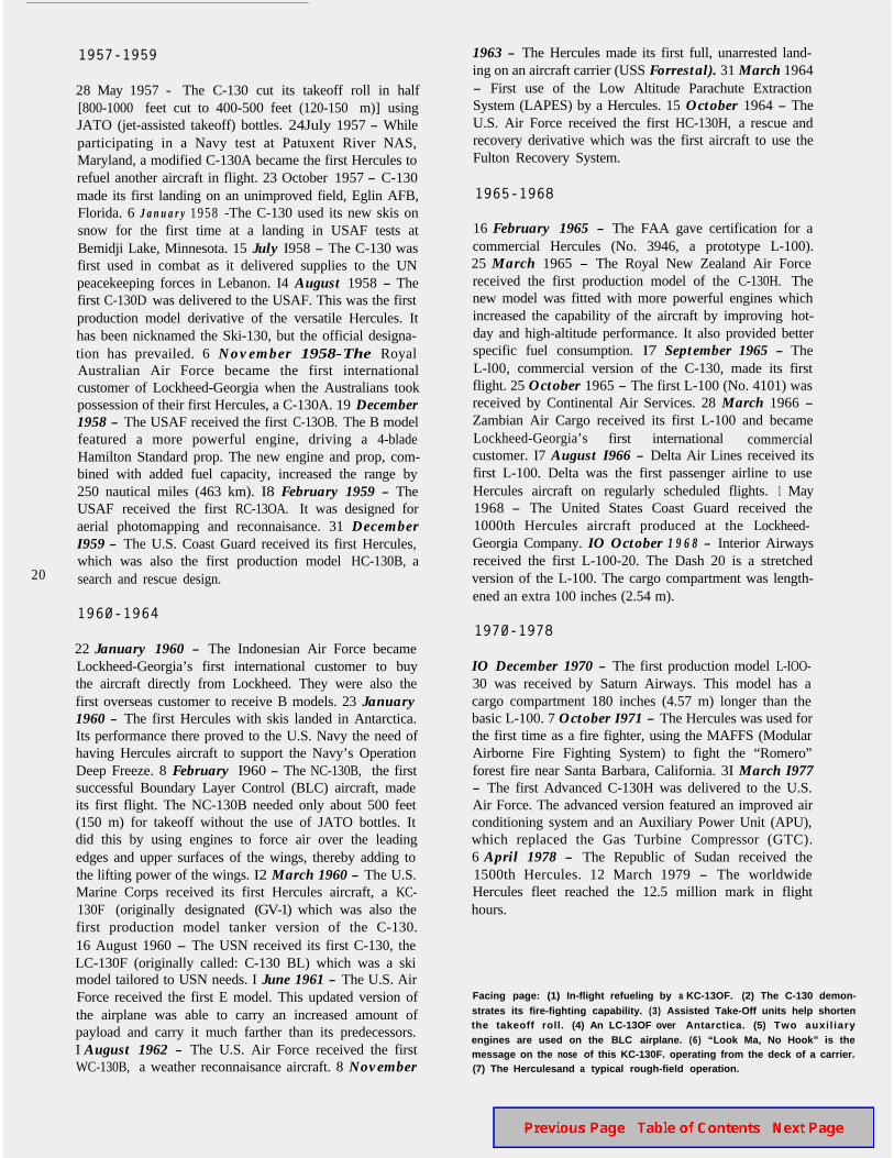
MILESTONES OF HERCULES AIRCRAFT
In February 1951, the U.S. Air Force announced that itwanted an aircraft that could land and take off in shortdistances and be able to make aerial as well as grounddelivery of personnel and cargo. Lockheed Corporationsubmitted its design in April of 1951, and on July 2 wastold this design had won the competition. August of 1951saw the beginning of work on two prototypes of theC-130 in Burbank, California. On September 19, 1952,the USAF ordered 7 of the new aircraft that were to bethe first military transports to have turboprop engines. Itwas also announced in September that the C-138 wouldbe produced at the Lockheed-Georgia Company inMarietta. Robert E. Gross, the president of Lockheed,predicted in October of 1952 that the C-130 would be the“workhorse of the Air Force.” The subsequent 25 yearshave proved that prediction to be not only true, but tobe an understatement.
1954
23 August - The clouds had dispersed and the smog hadthinned. After performing a series of taxi runs, StanleyBeltz, the command pilot, was ready. He began his groundroll. At 1348 Pacific Standard Time, having rolled lessthan a thousand feet, the prototype left the ground andbegan a 25-degree climb. Beltz, his crew and the firstYC-130 left Burbank behind as the clock of Herculesaircraft flight history began ticking. 11 November - Itwas announced that “Hercules” would be the name of thenew transport. The Reuben H. Donnelley Corp., judges ofthe “Name the Plane” contest, selected A. A. Pommer asthe winner. He had suggested the name “Griffin,” amythological creature with the head and wings of an eagleand the body of a lion. But, Lockheed Corporationmanagement thought “Hercules” more closely fit thefunction of the new transport. Of the 160 Lockheed-Georgians who had suggested the name Hercules, C. W.Flemister, an accountant, won a duplicate first prize inthe competition because of his reason for using the name“Hercules.”
1955
IO March - The first production C-130 (LAC No. 3001,Tail No. 33129) rolled off the assembly line and at 8:30a.m. was christened with a bottle of Chattahoochee Riverwater by Georgia Governor Marvin Griffin. 7 April -Bud Martin, assisted by Leo Sullivan, piloted the firstproduction Hercules on an 700-foot (240 m) ground roll,then into the air for its first flight.
1956
5 April - The first C-130 parachute delivery of cargo wasmade at El Centro AFB, California. 3May - The Herculesset its first significant world record as it paradropped 18A-22 containers weighing 29,000 pounds (13,150 kg) forthe multi-drop record. 16 May - a single pallet weighing27,000 pounds (12,250 kg) was parachuted from theHercules for the single-drop record. 18 June - The firstparatrooper jumped from the C-130 (El Centro). I3 July- LAC No. 3028 rolled off the production line. It was thefirst Hercules with the now-famous “Pinocchio” nose andSperry Gyroscope Company’s APN-59 radar. 9 December- The first C-130 (LAC No. 3050, Tail No. 50023,designated “City of Ardmore”) was delivered to anoperational unit, Tactical Air Command’s 463d TroopCarrier Wing at Ardmore AFB, Oklahoma. LAC No. 3050was the first production C-130 fitted with the 3-bladeAeroproducts propellers. They were hydraulically oper-ated, rather than electrically operated as were the Curtiss-Wright propellers that had been placed on the first 49production aircraft. The new props were found to bemuch better suited for the mammoth job of the C-130.
I9
1957-1959
20
28 May 1957 - The C-130 cut its takeoff roll in half[800-1000 feet cut to 400-500 feet (120-150 m)] usingJATO (jet-assisted takeoff) bottles. 24July 1957 - Whileparticipating in a Navy test at Patuxent River NAS,Maryland, a modified C-130A became the first Hercules torefuel another aircraft in flight. 23 October 1957 - C-130made its first landing on an unimproved field, Eglin AFB,Florida. 6 J a n u a r y 1958 -The C-130 used its new skis onsnow for the first time at a landing in USAF tests atBemidji Lake, Minnesota. 15 July I958 - The C-130 wasfirst used in combat as it delivered supplies to the UNpeacekeeping forces in Lebanon. I4 August 1958 - Thefirst C-130D was delivered to the USAF. This was the firstproduction model derivative of the versatile Hercules. Ithas been nicknamed the Ski-130, but the official designa-tion has prevailed. 6 November 1958-The RoyalAustralian Air Force became the first internationalcustomer of Lockheed-Georgia when the Australians tookpossession of their first Hercules, a C-130A. 19 December1958 - The USAF received the first C-13OB. The B modelfeatured a more powerful engine, driving a 4-bladeHamilton Standard prop. The new engine and prop, com-bined with added fuel capacity, increased the range by250 nautical miles (463 km). I8 February 1959 - TheUSAF received the first RC-13OA. It was designed foraerial photomapping and reconnaisance. 31 DecemberI959 - The U.S. Coast Guard received its first Hercules,which was also the first production model HC-130B, asearch and rescue design.
1960-1964
22 January 1960 - The Indonesian Air Force becameLockheed-Georgia’s first international customer to buythe aircraft directly from Lockheed. They were also thefirst overseas customer to receive B models. 23 January1960 - The first Hercules with skis landed in Antarctica.Its performance there proved to the U.S. Navy the need ofhaving Hercules aircraft to support the Navy’s OperationDeep Freeze. 8 February I960 - The NC-130B, the firstsuccessful Boundary Layer Control (BLC) aircraft, madeits first flight. The NC-130B needed only about 500 feet(150 m) for takeoff without the use of JATO bottles. Itdid this by using engines to force air over the leadingedges and upper surfaces of the wings, thereby adding tothe lifting power of the wings. I2 March 1960 - The U.S.Marine Corps received its first Hercules aircraft, a KC-130F (originally designated (GV-1) which was also thefirst production model tanker version of the C-130.16 August 1960 - The USN received its first C-130, theLC-130F (originally called: C-130 BL) which was a skimodel tailored to USN needs. I June 1961 - The U.S. AirForce received the first E model. This updated version ofthe airplane was able to carry an increased amount ofpayload and carry it much farther than its predecessors.I August 1962 - The U.S. Air Force received the firstWC-130B, a weather reconnaisance aircraft. 8 November
1963 - The Hercules made its first full, unarrested land-ing on an aircraft carrier (USS Forrestal). 31 March 1964- First use of the Low Altitude Parachute ExtractionSystem (LAPES) by a Hercules. 15 October 1964 - TheU.S. Air Force received the first HC-130H, a rescue andrecovery derivative which was the first aircraft to use theFulton Recovery System.
1965-1968
16 February 1965 - The FAA gave certification for acommercial Hercules (No. 3946, a prototype L-100).25 March 1965 - The Royal New Zealand Air Forcereceived the first production model of the C-130H. Thenew model was fitted with more powerful engines whichincreased the capability of the aircraft by improving hot-day and high-altitude performance. It also provided betterspecific fuel consumption. I7 September 1965 - TheL-l00, commercial version of the C-130, made its firstflight. 25 October 1965 - The first L-100 (No. 4101) wasreceived by Continental Air Services. 28 March 1966 -Zambian Air Cargo received its first L-100 and becameLockheed-Georgia’s first international commercialcustomer. I7 August I966 - Delta Air Lines received itsfirst L-100. Delta was the first passenger airline to useHercules aircraft on regularly scheduled flights. 1 May1968 - The United States Coast Guard received the1000th Hercules aircraft produced at the Lockheed-Georgia Company. IO October 1 9 6 8 - Interior Airwaysreceived the first L-100-20. The Dash 20 is a stretchedversion of the L-100. The cargo compartment was length-ened an extra 100 inches (2.54 m).
1970-1978
IO December 1970 - The first production model L-IOO-30 was received by Saturn Airways. This model has acargo compartment 180 inches (4.57 m) longer than thebasic L-100. 7 October I971 - The Hercules was used forthe first time as a fire fighter, using the MAFFS (ModularAirborne Fire Fighting System) to fight the “Romero”forest fire near Santa Barbara, California. 3I March I977- The first Advanced C-130H was delivered to the U.S.Air Force. The advanced version featured an improved airconditioning system and an Auxiliary Power Unit (APU),which replaced the Gas Turbine Compressor (GTC).6 April 1978 - The Republic of Sudan received the1500th Hercules. 12 March 1979 - The worldwideHercules fleet reached the 12.5 million mark in flighthours.
Facing page: (1) In-flight refueling by a KC-13OF. (2) The C-130 demon-strates its fire-fighting capability. (3) Assisted Take-Off units help shortenthe takeoff roll. (4) An LC-13OF over Antarctica. (5) Two auxi l iaryengines are used on the BLC airplane. (6) “Look Ma, No Hook” is themessage on the nose of this KC-130F. operating from the deck of a carrier.(7) The Herculesand a typical rough-field operation.
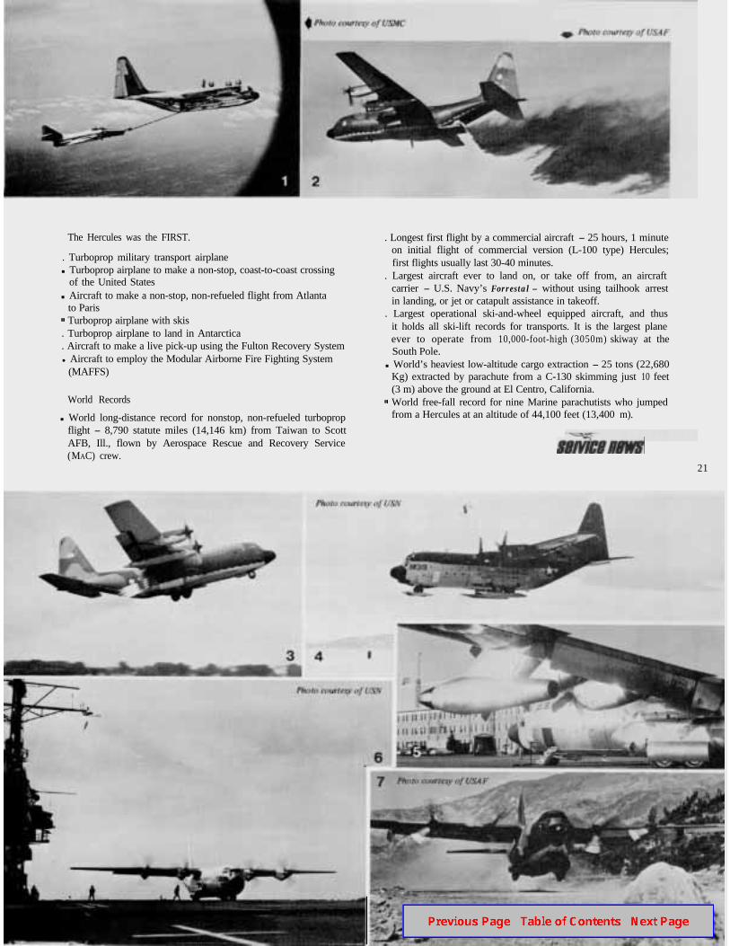
The Hercules was the FIRST.
. Turboprop military transport airplanen Turboprop airplane to make a non-stop, coast-to-coast crossing
of the United Statesn Aircraft to make a non-stop, non-refueled flight from Atlanta
to Paris Turboprop airplane with skis
. Turboprop airplane to land in Antarctica
. Aircraft to make a live pick-up using the Fulton Recovery Systeml Aircraft to employ the Modular Airborne Fire Fighting System
(MAFFS)
World Records
n World long-distance record for nonstop, non-refueled turbopropflight - 8,790 statute miles (14,146 km) from Taiwan to ScottAFB, Ill., flown by Aerospace Rescue and Recovery Service(MAC) crew.
. Longest first flight by a commercial aircraft - 25 hours, 1 minuteon initial flight of commercial version (L-100 type) Hercules;first flights usually last 30-40 minutes.
. Largest aircraft ever to land on, or take off from, an aircraftcarrier - U.S. Navy’s Forrestal - without using tailhook arrestin landing, or jet or catapult assistance in takeoff.
. Largest operational ski-and-wheel equipped aircraft, and thusit holds all ski-lift records for transports. It is the largest planeever to operate from 10,000-foot-high (3050m) skiway at theSouth Pole.
n World’s heaviest low-altitude cargo extraction - 25 tons (22,680Kg) extracted by parachute from a C-130 skimming just 10 feet(3 m) above the ground at El Centro, California.
World free-fall record for nine Marine parachutists who jumpedfrom a Hercules at an altitude of 44,100 feet (13,400 m).
21
A Promis ing FutureMAKING A GREAT PLANE GREATER
When people say something is “great,” they usuallymean it is either remarkable or very large. When describ-ing the Hercules aircraft, both meanings apply.
The most remarkable thing about the Hercules airplaneis its versatility. In its first 25 years, it has appeared in 47different versions. It has performed an uncounted varietyof missions which have ranged from serving as a flyinglounge for royal families, to hauling organic fertilizer, torefueling other aircraft in flight, to rescuing refugees fromthe ravages of nature or politics. Future modifications willincrease its versatility even more.
22
Two of the proposed new variations of the Hercules arethe Wide-Body STOL (short takeoff and landing) aircraft(WBS) and the improved Volume, Loadability and Speedaircraft (VLS). They would each have a maximum pay-load capacity of-68,000 pounds (30,840 kg) at a 2.5 Gload factor and 98,000 pounds (44,450 kg) at a 2.0 Gload factor. This increase over the 45,000-pound (20,410kg) maximum payload of the latest baseline Herculesmodel (at 2.5 G load factor) would be made possible bythe use of a restructured wing and the new HamiltonStandard 14-foot (4.3 m) diameter, 4-blade propellers.
The WBS would have a 3-way stretch in the cargo com-partment. It would be 19 inches (48.3 cm) wider, 28inches (71.1 cm) taller, and 80 inches (2.0 m) longer thanthat of the present baseline Hercules. The resulting com-partment would measure 48.1 feet (14.7 m) long, 11.7feet (3.6 m) wide and 11.3 feet (3.4 m) high. With a27,000-pound (12,250 kg) payload at 3.0 G load factor,the WBS could land in a distance of 1,810 feet (553 m).Other modifications would include a larger chord rudder,a larger dorsal fin, the addition of roll control spoilers,changing the single-piece Fowler flaps to compounddouble-slotted flaps, modification of the landing gear, andinstallation of a flush-mounted aerial refueling receptacleabove the flight station. This version can airlift 95% of anArmy mechanized infantry brigade’s equipment otherthan the main battle tanks.
The VLS would increase the overall volume 33% over thebaseline model by lengthening the cargo compartment15 ft (4.6 m) and widening it by 4.75 inches (12 cm). Theaft opening width would be increased by 18 inches(45.7cm) for easier loading and unloading. The averagecruising speed would be increased from 351 mph(564.9 kmh) to 414 mph (666.3 kmh). One reason forthe increased speed is a change to a T-tail like that of theC-141 and C-5. Another reason is the planned use of theproposed Detroit Diesel Allison engine, model 501-M7 1.This new power plant would develop 5,575 shaft horse-power (shp), an increase of 1375 shp over the Allison
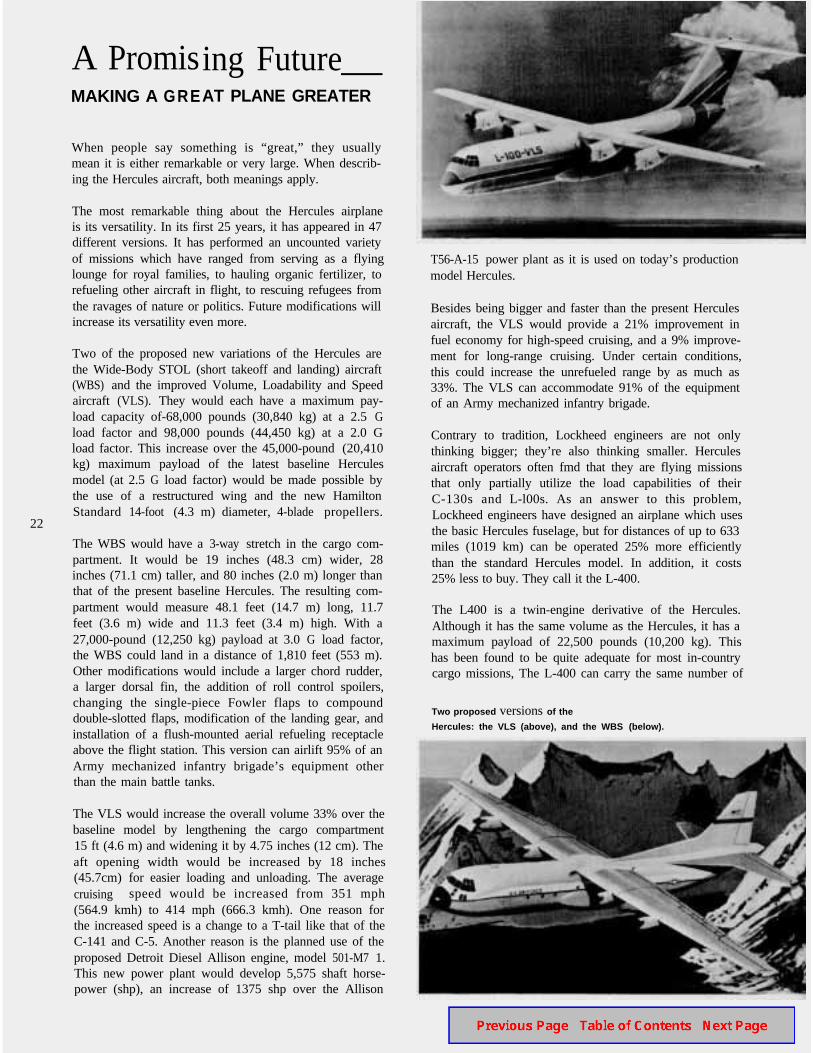
T56-A-15 power plant as it is used on today’s productionmodel Hercules.
Besides being bigger and faster than the present Herculesaircraft, the VLS would provide a 21% improvement infuel economy for high-speed cruising, and a 9% improve-ment for long-range cruising. Under certain conditions,this could increase the unrefueled range by as much as33%. The VLS can accommodate 91% of the equipmentof an Army mechanized infantry brigade.
Contrary to tradition, Lockheed engineers are not onlythinking bigger; they’re also thinking smaller. Herculesaircraft operators often fmd that they are flying missionsthat only partially utilize the load capabilities of theirC-130s and L-l00s. As an answer to this problem,Lockheed engineers have designed an airplane which usesthe basic Hercules fuselage, but for distances of up to 633miles (1019 km) can be operated 25% more efficientlythan the standard Hercules model. In addition, it costs25% less to buy. They call it the L-400.
The L400 is a twin-engine derivative of the Hercules.Although it has the same volume as the Hercules, it has amaximum payload of 22,500 pounds (10,200 kg). Thishas been found to be quite adequate for most in-countrycargo missions, The L-400 can carry the same number of
Two proposed versions of the
Hercules: the VLS (above), and the WBS (below).
troops, paratroops, litter patients, and many of the samevehicles as the baseline Hercules model. The big differenceis that its efficient range is somewhat more limited thanthe Hercules aircraft. Of course it makes up for this inoperating economy.
The real value of this model is its use as a cargo com-panion to the Hercules. An astounding 98% of the spares,facilities, mission equipment and support services areidentical for the two aircraft. A combination of the twowould let the customer use the L-400 for smaller missionsand leave the Hercules for the big jobs. The L-400 wouldprove a fine replacement for the aging fleet of DC-3s,C-l 19s and C-123s now in use, and the savings would beimmense.
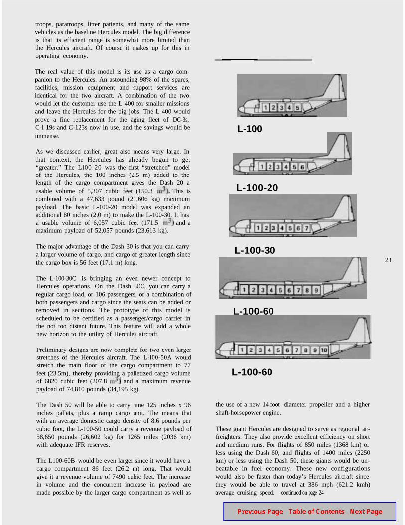
As we discussed earlier, great also means very large. Inthat context, the Hercules has already begun to get“greater.” The Ll00-20 was the first “stretched” modelof the Hercules, the 100 inches (2.5 m) added to thelength of the cargo compartment gives the Dash 20 ausable volume of 5,307 cubic feet (150.3 This iscombined with a 47,633 pound (21,606 kg) maximumpayload. The basic L-100-20 model was expanded anadditional 80 inches (2.0 m) to make the L-100-30. It hasa usable volume of 6,057 cubic feet (171.5 and amaximum payload of 52,057 pounds (23,613 kg).
The major advantage of the Dash 30 is that you can carrya larger volume of cargo, and cargo of greater length sincethe cargo box is 56 feet (17.1 m) long.
The L-100-30C is bringing an even newer concept toHercules operations. On the Dash 3OC, you can carry aregular cargo load, or 106 passengers, or a combination ofboth passengers and cargo since the seats can be added orremoved in sections. The prototype of this model isscheduled to be certified as a passenger/cargo carrier inthe not too distant future. This feature will add a wholenew horizon to the utility of Hercules aircraft.
Preliminary designs are now complete for two even largerstretches of the Hercules aircraft. The L-l00-50A wouldstretch the main floor of the cargo compartment to 77feet (23.5m), thereby providing a palletized cargo volumeof 6820 cubic feet (207.8 and a maximum revenuepayload of 74,810 pounds (34,195 kg).
The Dash 50 will be able to carry nine 125 inches x 96inches pallets, plus a ramp cargo unit. The means thatwith an average domestic cargo density of 8.6 pounds percubic foot, the L-100-50 could carry a revenue payload of58,650 pounds (26,602 kg) for 1265 miles (2036 km)with adequate IFR reserves.
The L100-60B would be even larger since it would have acargo compartment 86 feet (26.2 m) long. That wouldgive it a revenue volume of 7490 cubic feet. The increasein volume and the concurrent increase in payload aremade possible by the larger cargo compartment as well as
L-100
L-100-20
L-100-3023
L-100-60
L-100-60
the use of a new 14-foot diameter propeller and a highershaft-horsepower engine.
These giant Hercules are designed to serve as regional air-freighters. They also provide excellent efficiency on shortand medium runs. For flights of 850 miles (1368 km) orless using the Dash 60, and flights of 1400 miles (2250km) or less using the Dash 50, these giants would be un-beatable in fuel economy. These new configurationswould also be faster than today’s Hercules aircraft sincethey would be able to travel at 386 mph (621.2 kmh)average cruising speed. continued on page 24
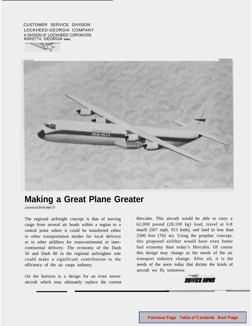
CUSTOMER SERVICE DIVISIONLOCKHEED-GEORGIA COMPANYA DIVISION OF LOCKHEED CORPORATlONMARIETTA, GEORGIA 30063
Making a Great Plane Greater
The regional airfreight concept is that of movingcargo from several air heads within a region to acentral point where it could be transferred eitherto other transportation modes for local deliveryor to other airlifters for transcontinental or inter-continental delivery. The economy of the Dash50 and Dash 60 in the regional airfreighter rolecould make a significant contribution to theefficiency of the air cargo industry.
On the horizon is a design for an even neweraircraft which may ultimately replace the current
Hercules. This aircraft would be able to carry a62,000 pound (28,100 kg) load, travel at 0.8mach (567 mph, 913 kmh), and land in less than2500 feet (762 m). Using the propfan concept,this proposed airlifter would have even betterfuel economy than today’s Hercules. Of coursethis design may change as the needs of the airtransport industry change. After all, it is theneeds of the users today that dictate the kinds ofaircraft we fly tomorrow.